Article

Comparison of Disturbance Compensators for a Discrete-Time System with Parameter Uncertainty

1
School of Mechanical Engineering, Shandong University, Jinan 250061, China
2
Key Laboratory of High Efficiency and Clean Mechanical Manufacture of MOE/Key National Demonstration Center for Experimental Mechanical Engineering Education, Jinan 250061, China
*
Author to whom correspondence should be addressed.
Appl. Sci. 2020, 10(18), 6219; https://doi.org/10.3390/app10186219
Submission received: 3 August 2020 / Revised: 26 August 2020 / Accepted: 31 August 2020 / Published: 8 September 2020
(This article belongs to the Section Mechanical Engineering)

Abstract

:
The control design for many industrial applications requires compensation for parameter uncertainty and external disturbance. Reported in many previous works, the parameter uncertainty and external disturbance are combined as a lumped disturbance, which is assumed to be smooth and bounded. However, for a discrete-time sliding mode control (DSMC) system, the above assumption may not hold. Here, the parameter uncertainty, along with its compensation in the DSMC system, are reconsidered and reevaluated. The influence of parameter uncertainty on the closed-loop system stability is first addressed. Then, the comparative investigation of the performance of six state-of-the-art disturbance compensators for parameter uncertainty compensation is conducted. Simulation results show that none of these compensators can effectively observe and compensate for the parameter uncertainty.

1. Introduction

The concept of sliding mode control (SMC) has been investigated extensively over the past few decades [1]. The essence of SMC is to drive the state trajectory onto a specified sliding surface and then, to keep it moving along this surface for the subsequent time. It is known that SMC in continuous-time exhibits an invariance property and the desired dynamics obtained on the sliding surface are robust against model uncertainty and external disturbance [2]. Nevertheless, the performance of an elaborately designed control algorithm in a continuous-time domain may deteriorate when implemented with direct digital applications. Therefore, discrete-time sliding mode control (DSMC) has attracted a lot of attention from both industry and academia [3].
Seen in the digital circuits, the control input of the DSMC can be applied only to the system at certain sampling instances, and the control effort remains constant over the entire sampling period. Some properties of continuous-time SMC, like the invariance property, no longer hold due to the discretization [4]. Hence, to obtain better control performance, it is necessary to employ disturbance observers or compensators for disturbance compensation.
Several disturbance compensators have been developed and combined with the DSMC [5] to compensate the effect of disturbance. The disturbance compensators that so far have demonstrated the most effective performance in DSMC systems are the N-steps delay estimation (NSDE) [6], the one-step delay estimation (OSDE) [7,8], the two-step delay estimation (TSDE) [9,10,11], the SMC disturbance compensator (SDC) [12], the decoupled disturbance compensator (DDC) [13,14], and the discrete-time disturbance observer (DTDO) [15]. It should be pointed out that in the aforementioned methods [5,6,7,8,9,10,11,12,13,14], a lumped disturbance term was adopted to represent the combined effect of the parameter uncertainty and external disturbance. Moreover, most of these previous works [5,6,7,8,9,10,11,12,13,14] made the assumption that the lumped disturbance term was smooth, slowly varying and bounded. Actually, the parameter uncertainty is coupled with the system states. High frequency chattering, which is the main drawback of the DSMC, always exists in the system states. Hence, the aforementioned slow varying assumption may not hold. Moreover, it also is inappropriate to mix the parameter uncertainty with external disturbance since they have different characteristics.
This paper reconsiders and reevaluates the parameter uncertainty along with its compensation in the DSMC system. Unlike existing similar works, this paper exhibits the following two merits simultaneously:
(1)
The stability of a DSMC system with parameter uncertainty is reevaluated analytically. Different from previous methods, parameter uncertainty is no longer regarded as part of the lumped disturbance but analyzed separately. The coupling relationship between parameter uncertainty and system state is considered.
(2)
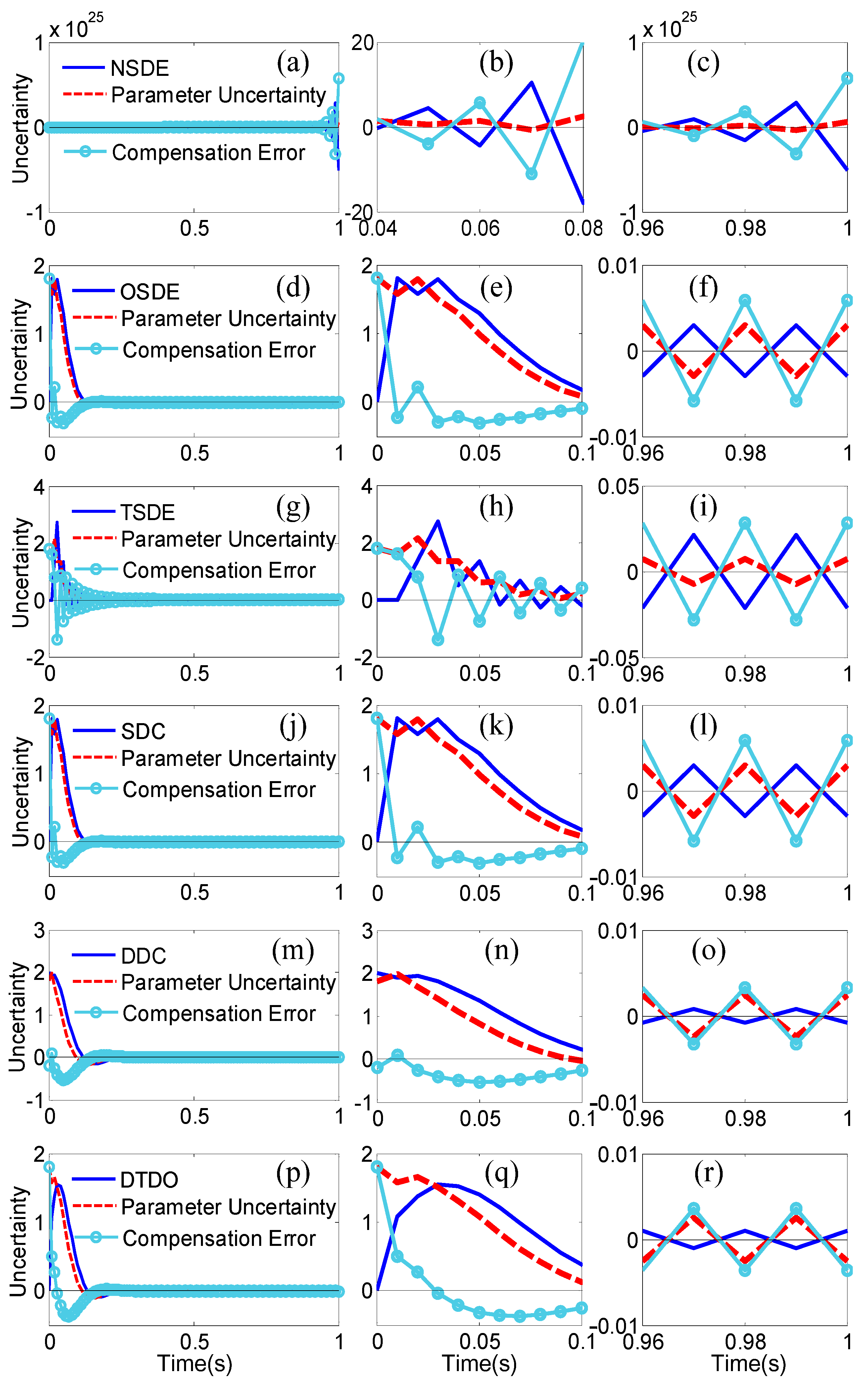
The performance of six state-of-the-art disturbance compensators including NSDE, OSDE, TSDE, SDC, DDC, and DTDO for parameter uncertainty compensation is comprehensively studied. The theoretical bases of the compensators are presented and compared in detail.
The remaining parts of this paper are organized as follows. The closed-loop stability of a DSMC system with parameter uncertainty is analyzed in Section 2. The comparative investigations of six state-of-the-art disturbance compensators are carried out in Section 3. Section 4 presents a series of simulation investigations and discussions on the control performance. Section 5 summarizes this paper.

2. Closed-Loop Stability Analysis

Consider the following discrete-time system Equation (1) under the influence of parameter uncertainty:
x ( k + 1 ) = ( Φ + Δ Φ ) x ( k ) + Γ u ( k ) + d ( k )
where x(k) Rn and u(k) R1 stand for the system state and control input, respectively. Ri (i = 1 or n, n is a positive integer) denotes the dimension of the vector. Φ and Γ represent the system matrix and vector, respectively. ΔΦ and d(k) denote the bounded parameter uncertainty and external disturbance, respectively. k represents the k-th step in the discrete-time system. It is noted that ΔΦ is coupled with x(k).

2.1. Traditional Stability Analysis

Found in most previous works, like [6,7,8,9,10,11,12,13,14,15], a lumped disturbance is introduced to denote the combined effect of the parameter uncertainty and external disturbance. Hence, the system model Equation (1) can be rewritten as Equation (2):
x ( k + 1 ) = Φ x ( k ) + Γ u ( k ) + f ( k )
where f(k) = ΔΦx(k) + d(k) is the lumped disturbance.
Using the help of state transformation z(k) = Tx(k), where T Rn, a controllable canonical form of Equation (2), is expressed as Equation (3):
z ( k + 1 ) = Φ ¯ z ( k ) + Γ ¯ u ( k ) + f ¯ ( k )
where
Φ ¯ = T Φ T 1 = [ 0 1 0 0 0 0 1 0 0 0 0 1 a 1 a 2 a 3 a n ] ,   Γ ¯ = T Γ = [ 0 0 0 1 ]
with ai (i = 1, 2, …, n) is the model coefficient, and f ¯ ( k )   = T f ( k ) .
Adopting the commonly used discrete-time sliding mode control (DSMC) reaching law [16], the control law u(k) can be represented as Equation (5):
u ( k ) = ( C ¯ Γ ¯ ) 1 [ C ¯ Φ ¯ z ( k ) ( 1 q ) s ( k ) + ξ sign ( s ( k ) ) ]
where q and ξ are the control parameters. s ( k )   = C ¯ z ( k )   = C x ( k ) is the switching function. C ¯ = [c1, c2, …, 1] is the gain vector of the switching function. Substituting Equation (5) into Equation (3) yields Equation (6):
z ( k + 1 ) = [ Φ ¯ Γ ¯ ( C ¯ Γ ¯ ) 1 ( C ¯ Φ ¯ ( 1 q ) C ¯ ) ] z ( k ) + f ˜ ( k )
where f ˜ ( k ) = f ¯ ( k ) Γ ¯ ( C ¯ Γ ¯ ) 1 ξ sign ( s ( k ) ) . The characteristic equation of the closed-loop system Equation (6) is Equation (7):
λ n + ( c n 1 ( 1 q ) ) λ n 1 + + ( c 1 ( 1 q ) c 2 ) λ ( 1 q ) c 1 = 0

2.2. Stability Analysis Considering Parameter Uncertainty

Considering Equation (1), the parameter uncertainty ΔΦ is coupled with the system state x(k). Since chattering always exists in the DSMC system [6], the commonly used smooth and slow varying assumptions on the disturbance [3,4,5,6,7,8,9,10,11,12,13,14,15,16] are not suitable for the coupled term ΔΦx(k). Hence, it is reasonable to analyze the closed-loop stability considering the parameter uncertainty separately.
Taking into account z(k) = Tx(k), Equation (8) can be obtained by noting Equation (1):
z ( k + 1 ) = ( Φ ¯ + Δ Φ ¯ ) z ( k ) + Γ ¯ u ( k ) + d ¯ ( k )
where d ¯ ( k )   = T d ( k ) . di (i = 1, 2, …, n) is the parameter uncertainty
Δ Φ ¯ = T Δ Φ T 1 = [ 0 1 0 0 0 0 1 0 0 0 0 1 d 1 d 2 d 3 d n ]
Substituting the controller Equation (5) into Equation (8) yields Equation (10)
z ( k + 1 ) = [ Φ ¯ + Δ Φ ¯ Γ ¯ ( C ¯ Γ ¯ ) 1 ( C ¯ Φ ¯ ( 1 q ) C ¯ ) ] z ( k ) + d ˜ ( k )
where d ˜ ( k ) = d ¯ ( k ) Γ ¯ ( C ¯ Γ ¯ ) 1 ξ sign ( s ( k ) ) . Based on Equation (10), the characteristic equation of the closed-loop system, Equation (11), can be obtained:
λ n + ( c n 1 ( 1 q ) + d n ) λ n 1 + + ( c 1 ( 1 q ) c 2 + d 2 ) λ + ( d 1 ( 1 q ) c 1 ) = 0
Unlike the traditional stability analysis, Equation (7), it follows from Equation (11) that the parameter uncertainty actually affects the closed-loop system stability. Hence, it is not appropriate to mix the external disturbance with parameter uncertainty. Even if the selection of q and C ¯ renders |λ|< 1 in Equation (7), it may not hold in Equation (9), and the closed-loop system still may be unstable.

3. Overview of Disturbance Compensators

Here, six different disturbance compensators, including the N-steps delay estimation (NSDE) [6], the one-step delay estimation (OSDE) [7,8], the two-step delay estimation (TSDE) [9,10,11], the SMC disturbance compensator (SDC) [12], the decoupled disturbance compensator (DDC) [13,14], and the discrete-time disturbance observer (DTDO) [15], are applied to the discrete-time system, Equation (1), with parameter uncertainty and are outlined and compared as follows.

3.1. N-Steps Delay Estimation

When f(k) is a function that changes slowly over time, it can be estimated by N (=1, 2, 3, …, is a positive integer) pre-stored values using an appropriate extrapolation method [6]. Equation (12) is the N-step delay estimation method [6]:
u d 1 ( k ) = C i = 1 ϑ ( k ) ( 1 ) i ϑ ( k ) ! ( ϑ ( k ) i ) ! i ! f ( k i )
where f(ki) = x(k + 1 − i) − Φx(ki) − Γu(z − i), the finite number function ϑ(k) is defined as Equation (13):
ϑ ( k ) = { k ,   k < N N ,   k N
When N is selected as 1, then ud1(k) is reduced to Equation (14):
u d 2 ( k ) = C f ( k 1 )
which is the widely used one-step delay estimation [7,8]. When N is selected as 2, then ud1(k) can be rewritten as Equation (15):
u d 3 ( k ) = 2 C f ( k 1 ) C f ( k 2 )
which is the recently developed two-step delay estimation [9,10,11].
Compared with ud2(k) and ud3(k), it is observed that ud1(k) is a more generalized disturbance compensator. ud2(k) and ud3(k) can be regarded as special cases of ud1(k). Regarding the three compensators, the lumped disturbance needs to satisfy the following assumption:
Assumption 1. 
The continuous-time counterpart of the lumped disturbance is smooth and bounded, and its N-th derivative is bounded also.
Considering if Assumption 1 holds, the compensation errors of ud1(k), ud2(k), and ud3(k) satisfy | u ˜ d 1 | = C| Nf(k)| ≤ Ω1, | u ˜ d 2 | = C|f(k) − f(k − 1)| ≤ Ω2, and | u ˜ d 3 | = C|f(k) − 2f(k − 1) + f(k − 2)| ≤ Ω3, respectively. and Nf(k) denote the difference operator and the N-th order difference of f(k), respectively. ud1(k), ud2(k), and ud3(k) can estimate and compensate the lumped disturbance with O(T2), O(T3), and O(TN+1) accuracy, respectively. Hence, as N increases, the estimation and compensation accuracy also increase, but the requirement for the smoothness of the disturbance signal also becomes higher.

3.2. Sliding Mode ControlDisturbance Compensator

The sliding mode control disturbance compensator (SDC) was first proposed by Qu et al., in [12]. Employing the popular reaching law Equation (16):
s ( k + 1 ) = ( 1 q ) s ( k ) ξ sign ( s ( k ) )
the expression of SDC is generated as Equation (17):
u d 4 ( k ) = i = 2 k { s ( i ) [ ( 1 q ) s ( i 1 ) ξ sign ( s ( i 1 ) ) ] }
Considering Equations (16) and (17), a deduction can be generated as Equation (18):
i = 2 k { s ( i ) [ ( 1 q ) s ( i 1 ) ξ sign ( s ( i 1 ) ) ] } = C f ( k 1 )
It is observed from Equations (17) and (18) that the cumulative differences between the switching function s(i) and the reaching law (1 − q)s(i − 1) − ξsign(s(i − 1)) present the generalized disturbance at the k − 1 steps. Moreover, Equation (17) also implies that the SDC ud4(k) is equivalent to the one-step delay estimation (OSDE) ud2(k). Hence, if C|f(k) − f(k − 1)| ≤ Ω2 holds, the compensation error of ud4(k) satisfies | u ˜ d 4 | ≤ Ω2.
The main disadvantage of SDC is that it is only valid for a slow time varying disturbance, just like the one-step delay estimation.

3.3. Decoupled Disturbance Compensator

The decoupled disturbance compensator is established in the discrete-time domain utilizing the sliding mode theory [13,14], which is shown as Equation (19):
u d 5 ( k ) = u d 5 ( k 1 ) + g [ s ( k ) ( 1 q ) s ( k 1 ) + ξ sign ( s ( k 1 ) ) ]
where g is the control parameter.
Stated in [13,14] by Eun, Y. and Lei, Y., this method allows the disturbance compensation dynamics to be adjusted separately from the controller dynamics, since the two dynamic modes are completely decoupled. It can be derived from Equations (1) and (19) that, if C|f(k) − f(k−1)|≤ Ω2 holds with |1 − g|< 1, then the compensation error satisfies | u ˜ d 5 | ≤ Ω2/g. Hence, this compensator is suitable for a slowly varying disturbance.
Agreeing with Equations (17) and (19), it is deduced that ud4(k) can be transformed into a form Equation (20) similar to ud5(k):
u d 4 ( k ) = u d 4 ( k 1 ) + [ s ( k ) ( 1 q ) s ( k 1 ) + ξ sign ( s ( k 1 ) ) ]
Different from SDC ud4(k), an additional control parameter g is introduced into DDC ud5(k), which enables the reduction of the disturbance compensation error u ˜ d 5 .

3.4. Discrete-Time Disturbance Observer

The discrete-time disturbance observer Equation (21) was proposed in [15] by Zhang, J. for discrete-time systems with either matched or mismatched disturbances:
u d 6 ( k ) = Λ u d 6 ( k 1 ) ( Λ I n ) f ( k 1 ) = Λ u d 6 ( k 1 ) ( Λ I n ) [ x ( k ) Φ x ( k 1 ) Γ u ( k 1 ) ]
where Λ = diag{λ1, λ2,…, λn} with |λi|< 1, i = 1, 2, …, n.
Similar to the previous five methods, the boundedness assumption of the lumped disturbance also is required in the discrete-time disturbance observer (DTDO). It was proved in [15] by Zhang, J. that the compensation error of DTDO | u ˜ d 6 | will converge to a bounded region whose width is greater than the upper bound of the lumped disturbance. Also, the upper bound of | u ˜ d 6 | is influenced by Λ, which can be adjusted to enhance the compensation accuracy. Additionally, it is observed from Equation (21) that the delay estimation method also is employed in DTDO to obtain the unmeasurable disturbance term f(k − 1).

4. Comparison and Results

The following discrete-time system under the influence of parameter uncertainty, Equation (1), is employed [6,16]. The system parameters are shown as (22):
Φ = [ 1.2 0.1 0 0.6 ] ,   Γ = [ 0 1 ] ,   Δ Φ = [ 0 0 0.3 0.2 ]
with Initial state x(0) assigned as [2, −6]T. The external disturbance d(k) is ignored since the focus of this paper is on the parameter uncertainty. The system model and the control methodologies are established using MATLAB software.

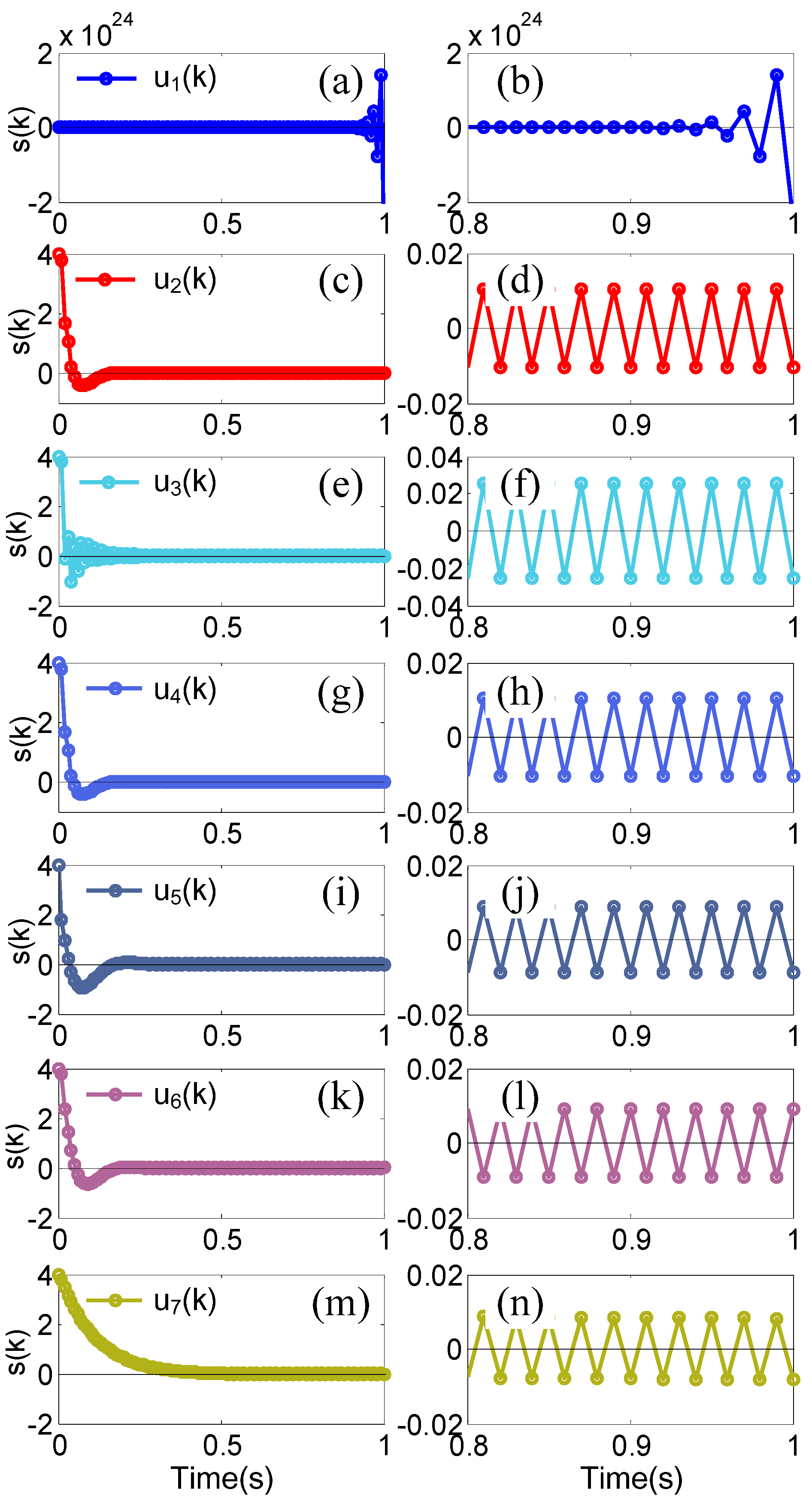
4.1. Principles for Compensators’ Comparison

Concerning the comparative evaluation of different methods, one key point is to select the appropriate principles to evaluate the performance level provided by each of the considered methods.
Here, a direct principle of compensation performance evaluation appears to be the compensation error of the parameter uncertainty ΔΦx(k), which can be calculated as u ˜ d i = ΔΦx(k) − udi(k), i = 1, 2, …, 6. This directly reflects the compensator’s ability to observe and compensate the parameter uncertainty.
Another principle is the width of the switching function s(k) in the steady state which, of course, reflects the performance of the compensator and, also, influences the final control accuracy of the closed-loop system.
Regarding a fair comparison, every disturbance compensator is combined with the same reaching law, Equation (16), to construct the discrete-time sliding mode controller (DSMC), i.e., ui(k), i = 1, 2, …, 6, and the DSMC system. The corresponding DSMC controllers and the closed-loop performance analyses can be found in [6,7,11,12,13,15], respectively. To better evaluate and compare the compensators’ performance, a DSMC controller without a disturbance compensator, i.e., u7(k) in [16] by Gao, W., is formulated based on the reaching law, Equation (16). Hence, the following seven DSMC controllers are adopted in simulation:
DSMC 1 u1(k):NSDEud1(k)+reaching law (16);
DSMC 2 u2(k):OSDEud2(k)+reaching law (16);
DSMC 3 u3(k):TSDEud3(k)+reaching law (16);
DSMC 4 u4(k):SDCud4(k)+reaching law (16);
DSMC 5 u5(k):DDCud5(k)+reaching law (16);
DSMC 6 u6(k):DTDOud6(k)+reaching law (16);
DSMC 7 u7(k): +reaching law (16).
A same sampling time is a basic condition for a fair comparison, which is selected as 0.01 s.
The control parameters q = 0.5, ξ = 0.01 and C = [5, 1] in these controllers are tuned by a trial-and-error method to ensure stable closed-loop systems. The additional parameters g = 0.5 in u5(k) and Λ = diag{0.4, 0.4} in u6(k) are adjusted using repetitive simulations to achieve optimal results. Moreover, we pick N = 5 in u1(k).

4.2. Simulation Results and Comparison

Figure 1a–r exhibits the simulation results of the disturbance compensators, parameter uncertainties and compensation errors, which are generated by the N-steps delay estimation (NSDE), the one-step delay estimation (OSDE), the two-step delay estimation (TSDE), the SMC disturbance compensator (SDC), the decoupled disturbance compensator (DDC),and the discrete-time disturbance observer (DTDO). The switching functions s(k) are illustrated in Figure 2a–n utilizing the seven different DSMC controllers, i.e., ui(k), i = 1, 2,…, 7. It is observed from Figure 1a–c and Figure 2a,b that the DSMC system is unlikely to be stable no matter how the control parameters of u1(k) are adjusted. The reason why the NSDE and u1(k) generate such poor results is mainly due to the unsmooth and fast varying parameter uncertainty ΔΦx(k). Since N = 5 in ud1(k), NSDE requires the fifth-order difference of parameter uncertainty to estimate the current value of ΔΦx(k). A chattering phenomenon exists in x(k). Hence, Assumption 1 cannot hold, and the fifth-order difference of parameter uncertainty may be quite large to cause system instability. When N decreases, the requirement for the smoothness of the disturbance signal also is reduced.
Comparing Figure 1d–i and Figure 2c–f, it is seen that the OSDE and u2(k) achieve a smaller compensation error and a smaller switching function, i.e., max{|s(k)|} = 0.011, in the steady state than the TSDE and u3(k), which is attributed to the lower difference order, i.e., N = 1. Regarding the unsmooth and fast varying parameter uncertainty, a larger N can cause system oscillation and even instability. Additionally, it is observed from Figure 1d–f,j–l and Figure 2c,d,g,h that the results of SDC and u4(k) are the same as those of the OSDE and u2(k), i.e., max{|s(k)|} = 0.011, which proves that the SDC ud4(k) is equivalent to the OSDE ud2(k). The simulation results of DDC/u5(k) and DTDO/u6(k) are depicted in Figure 1m–o, Figure 2i,j and Figure 1p–r, Figure 2k,l, respectively. It is found that the two methods further reduce the compensation error and the switching function, i.e., max{|s(k)|} = 0.0095, in the steady state than in the OSDE and u2(k). This is mainly owing to the additional control parameters.
It is notable, however, that the DSMC controller without disturbance compensators, i.e., u7(k), achieves the smallest switching function, i.e., max{|s(k)|} = 0.008 in Figure 2m,n, in the steady state than the other six methods. Hence, it is reasonable to deduce that these disturbance compensators have negative effects on the DSMC system with parameter uncertainty. Plotted in Figure 1 and Figure 2, the disturbance compensators, i.e., OSDE, SDC, DDC, and DTDO, estimate the real parameter uncertainty by its one step-delayed value. To achieve smooth and slowly varying disturbance, the impact of one step-delay on the estimation can be ignored and the compensation error may be small. Regarding unsmooth and fast varying parameter uncertainty ΔΦx(k), however, one step-delay has a large impact on the estimation and the compensation error is quite large. Due to the existence of chattering, the estimated values of these disturbance compensators are opposite to the values of the actual parameter uncertainty in the steady state. This is the reason why these disturbance compensators have negative effects on a DSMC system with parameter uncertainty.

5. Conclusions

This paper has addressed the parameter uncertainty along with its compensation in the discrete-time sliding mode controller (DSMC) system. Theoretical analysis of the DSMC system stability under the influence of parameter uncertainty has been reconsidered and reevaluated. The results show that even if the control parameters are adjusted so that the eigenvalues are within the unit circle, the DSMC system can still be unstable subjected to parameter uncertainty. Then, a detailed comparison of six existing disturbance compensators for the DSMC system with parameter uncertainty was presented. The considered disturbance compensators were the following: the N-steps delay estimation (NSDE), the one-step delay estimation (OSDE), the two-step delay estimation (TSDE), the SMC disturbance compensator (SDC), the decoupled disturbance compensator (DDC),and the discrete-time disturbance observer (DTDO). The theoretical bases of the compensators were presented and compared in detail. Moreover, simulation was carried out using seven different DSMC controllers. Considering the simulation results, they show that the parameter uncertainty in a DSMC system cannot be effectively compensated by all these compensators. The issue of extending the proposed method to practical systems will be studied in the future.

Author Contributions

Conceptualization, Z.G. and H.M.; methodology, Q.S.; validation, Z.G., H.M. and Q.S.; formal analysis, H.M.; investigation, Z.G.; resources, H.M.; data curation, Q.S.; writing—original draft preparation, Z.G.; writing—review and editing, H.M.; visualization, Q.S.; supervision, H.M.; project administration, H.M. All authors have read and agreed to the published version of the manuscript.

Funding

This research work was supported by the National Natural Science Foundation of China (51805327).

Conflicts of Interest

The authors declare that they have no conflict of interest.

Nomenclature

SymbolsDescription
Φ, ΓSystem matrix and vector.
ΔΦParameter uncertainty.
kk-th step in the discrete-time system.
d(k)Disturbance.
x(k)System state.
u(k)Control input.
f(k)Lumped disturbance.
z(k)System state after transformation.
s(k)Switching function.
CGain vector of switching function.
Difference operator.
q, ξ, gControl parameters.
λEigenvalue.
i, i = 1, 2, 3Upper bound.
ΛDiagonal matrix.
ϑ(k)Finite number function.

References

  1. Lin, C.-H.; Hsiao, F.-Y. Proportional-integral sliding mode control with an application in the balance control of a two-wheel vehicle system. Appl. Sci. 2020, 10, 5087. [Google Scholar] [CrossRef]
  2. Ponce, P.; Rosales, J.A.; Molina, A.; Ponce, H.; MacCleery, B. Designing a robust controller using SMC and fuzzy artificial organic networks for brushed DC motors. Energies 2020, 13, 3091. [Google Scholar] [CrossRef]
  3. Lin, S.; Zhang, W.; Wang, H. Controller designed via an adaptive reaching law for DSMC systems. IEEE Trans. Circuits Syst. II Exp. Briefs 2020, 67, 330–334. [Google Scholar] [CrossRef]
  4. Goyal, J.; Kamal, S.; Patel, R.; Yu, X.; Mishra, J. Higher order sliding mode control based finite-time constrained stabilization. IEEE Trans. Circuits Syst. II Exp. Briefs 2020, 67, 295–299. [Google Scholar] [CrossRef]
  5. Yu, X.; Wang, B.; Li, X. Computer-controlled variable structure systems: The state-of-the-art. IEEE Trans. Ind. Inf. 2012, 8, 197–205. [Google Scholar] [CrossRef]
  6. Ma, H.; Li, Y. A novel dead zone reaching law of discrete-time sliding mode control with disturbance compensation. IEEE Trans. Ind. Electron. 2020, 67, 4815–4825. [Google Scholar] [CrossRef]
  7. Du, H.; Yu, X.; Chen, M.; Li, S. Chattering-free discrete-time sliding mode control. Automatica 2016, 68, 87–91. [Google Scholar] [CrossRef]
  8. Su, W.; Drakunov, S.; Ozguner, U. An O(T2) boundary layer in sliding mode for sampled-data systems. IEEE Trans. Autom. Control 2000, 45, 482–485. [Google Scholar]
  9. Ma, H.; Li, Y.; Xiong, Z. Discrete-time sliding-mode control with enhanced power reaching law. IEEE Trans. Ind. Electron. 2019, 66, 4629–4638. [Google Scholar] [CrossRef]
  10. Ma, H.; Wu, J.; Xiong, Z. Discrete-time sliding-mode control with improved quasi-sliding-mode domain. IEEE Trans. Ind. Electron. 2016, 63, 6292–6304. [Google Scholar] [CrossRef]
  11. Ma, H.; Wu, J.; Xiong, Z. A novel exponential reaching law of discrete-time sliding-mode control. IEEE Trans. Ind. Electron. 2017, 64, 3840–3850. [Google Scholar] [CrossRef]
  12. Qu, S.; Xia, X.; Zhang, J. Dynamics of discrete-time sliding-mode-control uncertain systems with a disturbance compensator. IEEE Trans. Ind. Electron. 2014, 61, 3502–3510. [Google Scholar] [CrossRef] [Green Version]
  13. Eun, Y.; Kim, J.; Kim, K.; Cho, D. Discrete-time variable structure controller with a decoupled disturbance compensator and it application to a CNC servomechanism. IEEE Trans. Control Syst. Technol. 1999, 7, 414–423. [Google Scholar]
  14. Lei, Y.; Zhang, C.; Huang, J.; Fei, S. Discrete-time sliding-mode switching control scheme with disturbance observer and its application to superheated steam temperature systems. J. Dyn. Syst. Meas. Control Trans. ASME 2016, 138, 101003. [Google Scholar]
  15. Zhang, J.; Shi, P.; Xia, Y.; Yang, H. Discrete-time sliding mode control with disturbance rejection. IEEE Trans. Ind. Electron. 2019, 66, 7967–7975. [Google Scholar] [CrossRef]
  16. Gao, W.; Wang, Y.; Homaifa, A. Discrete-time variable structure control systems. IEEE Trans. Ind. Electron. 1995, 42, 117–122. [Google Scholar]
Figure 1. Disturbance compensators, parameter uncertainties and compensation errors: (a) N-steps delay estimation (NSDE); (b,c) Zoom view of Figure 1a; (d) One-step delay estimation (OSDE); (e,f) Zoom view of Figure 1d; (g) Two-step delay estimation (TSDE); (h,i) Zoom view of Figure 1g; (j) Sliding mode control disturbance compensator(SDC) (k,l) Zoom view of Figure 1j; (m) Decoupled disturbance compensator (DDC); (n,o) Zoom view of Figure 1m; (p) Discrete-time disturbance observer (DTDO); (q,r) Zoom view of Figure 1p.
Applsci 10 06219 g001
Figure 2. Switching function s(k): (a) u1(k); (b) Zoom view of Figure 2a; (c) u2(k); (d) Zoom view of Figure 2c; (e) u3(k); (f) Zoom view of Figure 2e; (g) u4(k); (h) Zoom view of Figure 2g; (i) u5(k); (j) Zoom view of Figure 2i; (k) u6(k); (l) Zoom view of Figure 2k; (m) u7(k); (n) Zoom view of Figure 2m.
Applsci 10 06219 g002

