Article

Robust Localization of the Mobile Robot Driven by Lidar Measurement and Matching for Ongoing Scene

1
Shanghai Key Laboratory of Intelligent Manufacturing and Robotics, School of Mechatronic Engineering and Automation, Shanghai University, Shanghai 200444, China
2
Shanghai Robot Industrial Technology Research Institute, Shanghai 200063, China
*
Authors to whom correspondence should be addressed.
Appl. Sci. 2020, 10(18), 6152; https://doi.org/10.3390/app10186152
Submission received: 25 July 2020 / Revised: 23 August 2020 / Accepted: 1 September 2020 / Published: 4 September 2020
(This article belongs to the Section Computing and Artificial Intelligence)

Abstract

:
Aiming at the localization problem of mobile robot in construction scenes, a hybrid localization algorithm with the adaptive weights is proposed, which can effectively improve the robust localization of mobile robot. Firstly, two indicators of localization accuracy and calculation efficiency are set to reflect the robustness of localization. Secondly, the construction scene is defined as an ongoing scene, and the robust localization of mobile robot is achieved by using the measurement of artificial landmarks and matching based on generated features. Finally, the experimental results show that the accuracy of localization is up to 8.22 mm and the most matching efficiency is controlled within 0.027 s. The hybrid localization algorithm that based on adaptive weights can realize a good robustness for tasks such as autonomous navigation and path planning in construction scenes.

1. Introduction

The localization with robustness of mobile robot is a characteristic that describes the ability to maintain its original or expected state. With the continuous improvement of the construction industry, the mobile robot technology is being widely used in the construction industry [1]. More kinds of robots, such as the masonry robot and 3D printing robot, are endowed with mobility to accomplish the structure manufacturing, handling and assembly tasks [2,3,4]. The localization issue becomes more critical for them. The construction scene is an empty and unstructured environment, the measured uncertainty and noise of sensors cannot be ignored. Therefore, focusing on the robust localization of mobile robot in construction scene can improve the monitoring efficiency of construction and bring a great potential for automation and intelligent prefabrication [5,6].
For the localization of mobile robot in the empty scenes, the artificial landmarks are usually set to achieve it by scholars. A global localization system that based on artificial beacons was developed by visual sensors for indoor environments [7]. For improving the adaptation of sensors and computing power, an artificial beacon was designed to calculate poses of mobile robot by trigonometric functions [8]. Also, the accuracy of localization for mobile robot was affected by numbers of sensors and errors of their placements. A new three object triangulation algorithm that solved the limitation of the specific beacon ordering, beacon placement, and the working range of the triangle was proposed, which showed a fast calculation efficiency [9]. Similarly, an active beacon angle measurement system that was proposed to realize the robust localization of mobile robot by measuring angles of identified beacons [10]. An error model for a robot’s pose based on triangulation from three landmarks was proposed in [11], and the uncertainty of landmark’s location was represented by Gaussian distribution to calculate the robot pose error. In addition, the photoelectric artificial landmarks were pre-marked in a large-scale space, and a multi angle intersection algorithm was established to show an accurate measurement in three-dimensional position and orientation of mobile robot [12]. From the above works, the localization of indoor scenes for mobile robot can be achieved by the triangulation or trilateral measurement methods with artificial landmarks. However, the effects of sensor noise and measured errors of landmarks on the mobile robot’s localization are ignored, so the robust localization can be improved further by filtering or optimization.
The filtering method is a key tool to improve the localization accuracy of mobile robot. It can effectively solve the ambiguity and kidnapping problems in the process of localization. Among them, the commonly filtering methods that used in robot localization are Particle Filtering (PF), Kalman Filtering (KF), and their variants. For the consistency of vehicle localization, a novel global localization system based on PF was presented in [13,14], which improved the convergence relationship and accelerated to the convergence process of particles. A triangulation algorithm that based on combination of Unbiased Finite Impulse Response (UFIR) and KF was introduced to improve localization accuracy of mobile robot [15]. Font Llagunes et al. [16] fused external measurement sensor and odometer information through Extended Kalman Filter (EKF), and adopted triangulation method to improve localization accuracy of mobile robot. Also, a localization scheme based on Invariant Extended Kalman Filter (IEKF) for mobile robot was developed by the Kinect point cloud [17]. For further improvement of localization accuracy and stability of mobile robot, the measured noise of Lidar to artificial landmarks was considered [15,18], and the localization method based on an Adaptive Unscented Kalman Filter (AUKF) was used to improve the localization of mobile robot [18]. The above researches have improved the localization accuracy or computational efficiency of mobile robot through the filter framework. However, the fusion mechanism of different sensors is complex and has the disadvantages of unsynchronization and uncertainty. In addition, the localization methods that mentioned above are not directly applied well in the scene, where the recognizable landmarks are blocked by the new ongoing features. So, the scan matching technology can be adopted as an optimization method to improve robust localization of mobile robot.
Simultaneous localization and mapping is called SLAM for short, that is, in an unknown environment, mobile robot can use sensors such as Lidar or camera to perceive external information to achieve localization and mapping. With the rapid development of intelligent robot technology, SLAM technology has been widely used in robotics and unmanned driving fields [19,20,21]. It can greatly improve the localization performance of mobile robot in the construction scene. One of the key tools for robust localization of mobile robot is the scan matching. A typical method for scan matching is the Iterative Closest Point (ICP) proposed by Besl etc. [22]. It was used to register two laser scans to determine the relative transformation with the low complexity. However, the ICP method had also the disadvantages. It was given the accurate initial values to avoid falling into local optimal values [22,23]. For the robust localization of mobile robot, a novel robust localization method for mobile robot was proposed in [24], and the particle loss was also solved based on the particle swarm optimization strategy. A scan matching algorithm based on the combination of 2D laser and odometer was adopted to reduce the localization error of mobile robot in an indoor environment [25]. Also, an Anchor Point Relation (APR) pattern matching algorithm was adopted to realize the real-time search between the most matching lasers and the known reference lasers, which improved the localization robustness of mobile robot [26]. To reduce the influence of noise, the localization accuracy of mobile robot was improved through the weighted scanning matching method [27]. A matrix matching method [28] and the method that based on the Radial distance and Incident Angle (RIA) [29] were adopted, which estimated efficiently the transformation of two locations. In addition, some other scan matching methods were also studied. A polar coordinate scan matching method (PSM) based on point-to-point was proposed to achieve a rapid data association, and the matching results demonstrated high accuracy of localization for mobile robot [30]. Normal Distributions Transform (NDT) [31] and a grid-based 2D map matching with multiple Normal Distributions (NDs) were presented, to improve the global matching efficiency and robustness of localization [32]. Without the need of landmarks, an optimization method that based online segment matching was proposed to reduce the matching error of two positions for mobile robot [33]. Also, Monte Carlo, Kullback–Leibler Distance (KLD) sampling was adopted to estimate the pose of mobile robot [34].
The traditional localization method of mobile robot is to use laser scanners, vision systems, sonar and other sensors to identify the artificial or natural features of the scene to achieve the localization. However, due to the absence of natural landmarks or the difficulty in extracting features, the localization method that mentioned above cannot be well applied into the construction scenes. Therefore, in this paper, we propose a novel localization algorithm for mobile robot by combining features from original scene and ongoing buildings. Without considering the ground inclination, the artificial landmarks are set in the scene firstly. Then, according to the sequence of construction processing, the features of artificial landmarks and ongoing buildings at different locations are extracted. At last, a mix of artificial landmarks and ongoing buildings aided 2D localization (MALOBAL) method is developed, which lays the key foundation for the following tasks in perception, scene understanding, Lidar navigation and path planning.
The main contribution of the paper is summarized as follows:
(a)
Defines the construction environment as an “ongoing scene” that differs from static and dynamic environment.
(b)
Creates a novel robust localization model combining artificial landmarks of the original scene with ongoing features.
(c)
Proposes a hybrid localization algorithm based on adaptive weights driven by Lidar measurement and feature matching.
(d)
Compares the matching accuracy and efficiency of ICP based on the generated features to typical ICP based on the whole scenes.
The remainder of this paper is organized as follows. We first briefly introduce robot modeling, the definition and construction of the ongoing scene (Section 2). We then propose a novel robust localization method based on Lidar measurement and matching for mobile robot in ongoing scene (Section 3). Next, we introduce the localization experiment for mobile robot of ongoing scene (Section 4), which is designed to demonstrate the robust localization and present experimental results that obtained from the tests (Section 5). Finally, the paper concludes with an outlook to future research in ongoing scene (Section 6).

2. Problem Formulation

2.1. Definition of the Ongoing Scene
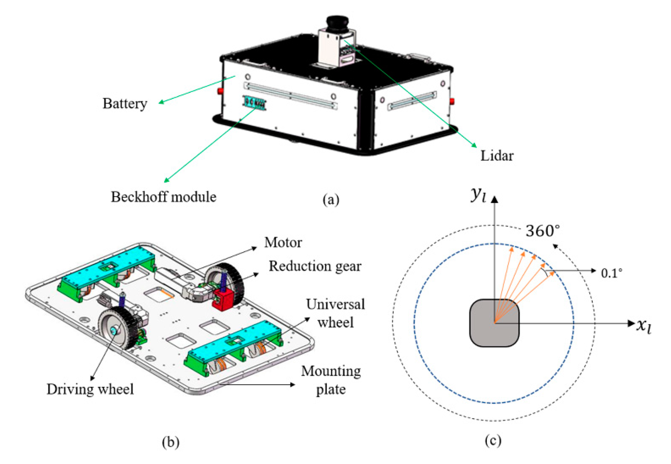
For effectively monitoring the construction efficiency of a building project, BIM, as an emerging strategy, is commonly used for realizing real-time monitoring of the construction site [35]. The mobile robot can be used as a data storage medium to capture valuable information about the ongoing construction process by using self-localization and mapping sensing technology. Also, it can achieve the construction of the scene in an orderly manner by matching the digital model with the 1:1 scale of its construction location [3,36]. So, the paper defines the construction scene as an “ongoing scene”. The ongoing scene is different from static and dynamic scenes. It can be structured or unstructured, and the initial state of it has no identifiable natural features. In addition, with the planning requirements of task, the state of the scene will change according to a certain regular order, and the newly added information of the scene will grow gradually. According to the order of tasks, the mobile robot performs mobile operations and constructs the new building information in a certain order. As a result, the ongoing scene is constructed from scratch to complete gradually.

2.2. Robot Modeling

The robot model is composed of a two-wheel driven mobile robot and a 2D Lidar, as shown in Figure 1a. The two-wheel driven mobile robot mainly include the following parts of Beckhoff module and the hardware (Figure 1b, such as two driving wheels, universal wheels, and so on. The whole system is electrically powered by lithium-ion batteries, which enable it to operate for about 6 h. The drive system can achieve a maximum speed of 2 m/s on flat terrain. The Beckhoff module is a control system to implement the planning task from the upper computer via a wireless router. The Beckhoff is also a microcomputer, and it runs a real-time enabled version of windows with the visual studio. Also, a 2D Lidar that shown in Figure 1c is attached to the center of mobile robot, and it can rotate anticlockwise with the 360 degrees coverage field around the vertical line of the mobile robot. The resolution of 2D Lidar is 0.17 degrees, and it can perceive scanning information from the environment up to 30 m. In addition, the ultrasonic and inertial measurement unit are also equipped with the mobile robot.

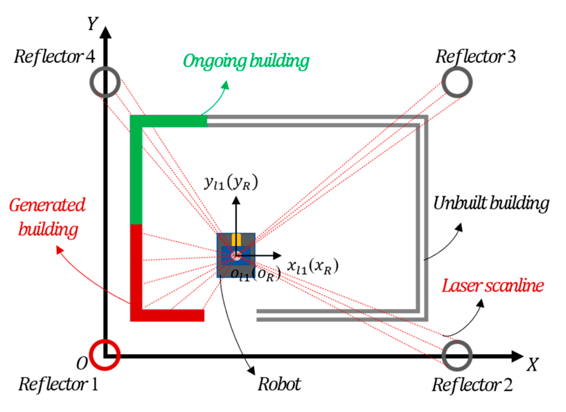
2.3. Construction of the Ongoing Scene for Mobile Robot

For improving the quality and efficiency of building construction, a 2D drawing of the ongoing building is designed by the CAD software [4,37]. From the top view of Figure 2, the actual operating range adopts a 1:1 scale to consist with the drawing, and as a digital model to the mobile robot [36,38]. Then, the artificial landmarks with high reflectivity films are set in the ongoing scene, and the intensity information of them are extracted to determine the initial position of the mobile robot. Finally, according to the sequence of the ongoing buildings, the scanning matching algorithm based on generated buildings is proposed to achieve the localization of mobile robot. The Figure 2 shows a construction process of the ongoing scene for the mobile robot.
In Figure 2, a localization system of the mobile robot is proposed to be applied into the ongoing scene. The coordinate system of the Lidar coincides with the coordinate system of the mobile robot, and they are expressed as X l O l Y l and X R O R Y R , separately. In addition, 4 reflective columns are evenly placed in the ongoing scene. The first reflective column is set as the origin point of the absolute coordinate system X g O g Y g , and the equation in the global coordinate system is defined as
r g = [ x R g , y R g , θ ]
where the parameters x R g and y R g represent the position of mobile robot in the global coordinate system, respectively, and the parameter θ refers to the angle of the coordinates x R g and y R g . In Figure 2a, the initial state of the mobile robot is set as [ x R 1 g , y R 1 g , θ 1 ] , and the completed state that shown in Figure 2b is also set as [ x R n g , y R n g , θ n ] .
The initial state of ongoing scene is empty and lacks geometric texture features, which causes the failure in localization for mobile robot to some extent. So, ignoring the influence of the manipulator to the localization of mobile robot, the paper combines the measurement of artificial landmarks with scanning matching of ongoing buildings to improve the robust localization of mobile robot. A detailed analysis of localization will be described in following chapters.

3. Localization of Mobile Robot in Ongoing Scene

Faced with the intelligent construction of buildings, the primary task is to carry out localization and navigation of mobile robot under different operating conditions. In order to improve the localization accuracy of the mobile robot, blue pillars and brown floors were used to match the 3D point cloud to obtain the end of the mobile construction manipulator, and gave feedback to Grasshopper for brick stacking [3]. Turek, W. et al. [36] described the mobility of the mobile construction robot when constructing walls in an unknown environment. The metal disk was scanned and its position was defined as the origin of the coordinate system in the CAD model. Then, the new working location of the mobile robot was determined based on the measurement to the landmark. However, the localization method in [36] was insufficient, and the artificial landmark was moved frequently, which led to cumulative errors in measurement between the actual position and the CAD model. As a result, the safety risks of construction workers and low efficiency of intelligent construction were still remained.
For the localization of mobile robot in the ongoing scene, the paper starts from the construction process with the clockwise sequence. When the generated buildings were constructed according to the scale of the construction drawing, the scene was divided into three construction states (Figure 3). Due to the mutual occlusion of artificial landmarks and generated buildings, their geometrical characteristics in different locations were extracted, respectively. Considering the quantitative differences between the two characteristics, the weighting factors were set relatively and the MALOBAL method was proposed to achieve the robust localization. Taking the construction from scratch to completion as an example, the localization process of mobile robot is shown in Figure 3.

3.1. Localization Based on Artificial Landmarks in an Ongoing Scene

In order to reach the designated working location accurately, the paper adopts the three-sided measurement method based on reflectors [13] to ensure an initial position of mobile robot. The surface of the reflector is pasted with a high-reflectivity film, and its intensity information can be extracted by Lidar to achieve the localization. When mobile robot moves to a certain site of the ongoing scene, the robot adopts Lidar to extract the intensity value of the reflector to assist in localization. As shown in Figure 4, the extracted process to reflectors and localization for mobile robot are described. Firstly, a global coordinate and the local coordinate of Lidar are set to X O Y and x l 1 o l 1 y l 1 , respectively. Then the coordinate of the center to the three reflectors are set separately to p 1 ( x r 1 , y r 1 ) , p 2 ( x r 2 , y r 2 ) and p 3 ( x r 3 , y r 3 ) . The reflector p 1 is set as the origin of the scene’s global coordinate system, and its radius is expressed as D r / 2 . When the mobile robot arrives at station A, the Lidar to the global coordinate system is set as (x’, y’, μ). At this time, the distances of Lidar sensor to the center [ p 1 , p 2 , p 3 ] of three reflective cylinders are represented as [ d 1 , d 2 , d 3 ] . The distance between the reflector and Lidar is different, the number of scanned points is also different. Just as shown in Figure 4, the red dots attached to reflectors are the scanned laser points. For the further research to the localization of mobile robot based on reflectors, the paper will describe in detail from the following two aspects: (1) Feature extraction of reflectors; (2) localization of scene-based reflectors.

3.1.1. Extraction of Artificial Landmarks

Firstly, the artificial landmarks are set in the scene, a global coordinate system of the scene is constructed. Then, the median filtering method is used for data processing. As a result, the filtered polar coordinate data ( ρ i , θ i ) is transformed into rectangular coordinate data ( x i , y i ) . F i = [ x i , y i ] , that is, the formula is as follows:
{ x i = ρ i cos θ i y i = ρ i sin θ i i = 1 , 2 , 3 , , n .
Then, the distance d i , i + 1 of adjacent data points is calculated based on the adaptive clustering algorithm, and it is compared with the clustering threshold t. The formula is as follows:
d i , i + 1 = d i s ( F i , F i + 1 )
t = ρ i 1 ( sin Δ φ / sin ( λ Δ φ ) ) + σ ρ
where Δ φ , the angular resolution of the Lidar sensor, is set 0.25°. A constant parameter λ is set 10 , and σ ρ represents the error of distance value. If d i , i + 1 t , then F i and F i + 1 are of the same cluster, otherwise, they are different clusters. According to the experimental tests, Δ φ = 0.25 , λ = 10 , σ ρ = 10   mm .
After obtaining the clustering data, the clusters are divided into the reflector and non-reflector by the extraction of the intensity information I i . The diameter and intensity of the reflector are set D r and I r , separately. When I r I i , the clustering data that extracted is the features of the reflector. Assuming the reflector 1 that in coordinate system of Lidar is ( x r 1 , y r 1 ) , the point set of the reflector is expressed as S i = ( x i , y i ) , i = 1 , 2 , , n . Then, the geometric equation of the circle is shown as:
( x i x r 1 ) 2 + ( y i y r 1 ) 2 = D r 2 4   ( i = 1 , 2 , n )
and the objective equation that based on the least square method is obtained as:
F = i = 1 n [ ( x i x r 1 ) 2 + ( y i y r 1 ) 2 D 2 4 ] 2 .
Take the partial derivative of Equation (6) and calculate the coordinates of the central position of the reflector ( x r 1 , y r 1 ) .

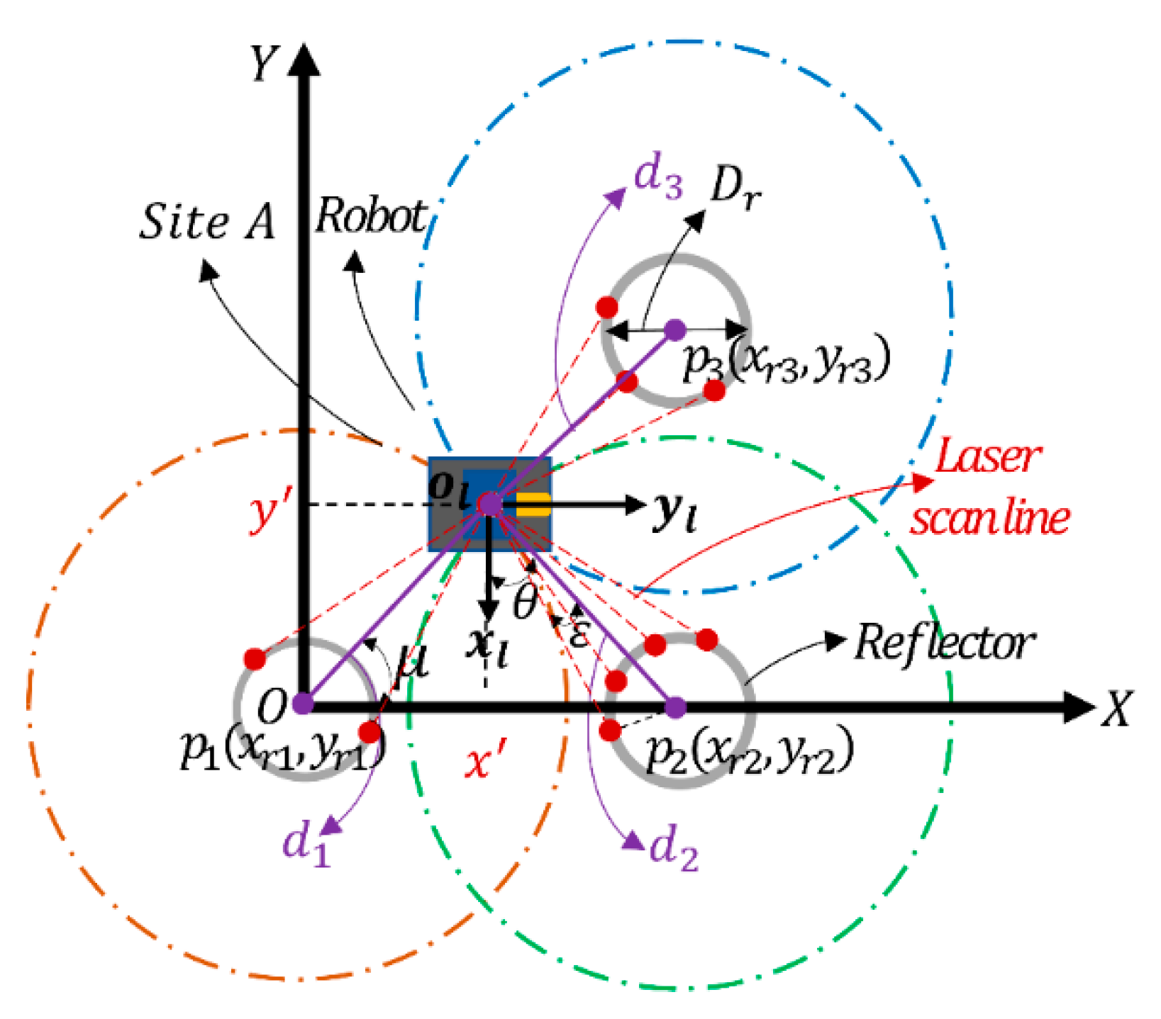
3.1.2. Localization of Ongoing Scene Based on Reflectors

Due to factors of sensor noise and differences in numbers of features, the paper adopts the repeated measurement value to calculate the positions of reflectors. Therefore, the nearest distance between the Lidar and the surface of the i-th reflector column ρ i is expressed as follows:
ρ i = d i D r / 2 , ( i = 1 , 2 , 3 )
When the number of reflectors that scanned by the Lidar is greater than or equal to three, the three-sided measurement is used to realize the localization of mobile robot. In addition, [13] concludes that the more artificial landmarks are set in the indoor environment, the localization accuracy of mobile robot will be higher. However, when the number of artificial landmarks is set too much, the difficulty in identifying them increases and the anti-interference ability will be weakened accordingly. Therefore, in this paper, four reflectors are evenly placed in the ongoing scene, and the trilateration method is used to complete the localization of mobile robot. The parameter definition of Figure 4 is
{ ( x r 1 x ) 2 + ( y r 1 y ) 2 = ( ρ 1 + D r / 2 ) 2 ( x r 2 x ) 2 + ( y r 2 y ) 2 = ( ρ 2 + D r / 2 ) 2 ( x r 3 x ) 2 + ( y r 3 y ) 2 = ( ρ 3 + D r / 2 ) 2 .
From above equations, the position of Lidar in the global coordinate system is set as ( x , y ) . Also, due to the fitting circles formed by the reflector cannot be accurately intersected at one point, the least square method is adopted to reduce the intersection errors of circles. As a result, the optimal calculation result approximates the theoretical value. At this time, the estimated coordinate of Lidar is calculated as
x = ( ( ρ 1 + D r / 2 ) 2 ( ρ 2 + D r / 2 ) 2 + x r 2 2 ) / 2 x r 2
y = ( ( ρ 1 + D r / 2 ) 2 ( ρ 3 + D r / 2 ) 2 + x r 3 2 + y r 3 2 2 x x r 3 ) / 2 y r 3
μ = 1 m t = 1 m a r c t a n ( y t / x t ) , t = 1 , 2 , , m .
Finally, the global coordinate of the Lidar in Figure 4 is set in the same direction to the robot. Therefore, the rotation matrix and translation vector are separately as zero and T, and the pose of the global coordinate system for mobile robot is
[ x R y R ] = [ x y ] + T .
From above Formula (12), the pose of mobile robot is estimated.

3.2. Localization of Artificial Landmarks and Generated Buildings Based on Adaptive Weights

The artificial landmarks that set in ongoing scene are gradually blocked by the generated buildings, which leads to a poor localization or failure for mobile robot. So, we regard the generated buildings as the observation features, and adopt the matching method based on ICP to achieve localization of mobile robot. Figure 5 has shown a robust localization of mobile robot at a designated location. The ongoing scene has four artificial landmarks and generated buildings, and the reflector 1 is blocked by the generated building. At this time, mobile robot can be located through the other three reflectors and the generated buildings. Therefore, the paper proposes a robust localization model that based on the fusion of reflectors and ongoing buildings. Firstly, according to the coordinate of the reflectors in the prior scene, the trilateration method is used to estimate the initial position of mobile robot. Secondly, with the gradual generation of buildings under construction in the scene, geometric features of the reflectors and generated buildings are simultaneously extracted by Lidar. Then, the two geometric primitives are regarded as observation features, and the ICP algorithm is used to achieve the data association between two adjacent locations to complete robust localization of mobile robot. Considering the influence of measurement noise and matching errors to the localization model, the normalized weighted factors are set to adjust the localization accuracy and efficiency adaptively, and the localization with robustness of mobile robot is also improved.

3.2.1. Frame of ICP Based on Generated Buildings

Although the localization accuracy based on three-sided measurement is high and does not need the initial pose, the more numbers of artificial landmarks need to be set and moved by constructors. So, the ongoing scene can be regarded as a low-speed dynamic changing environment with a certain sequence. As the buildings are gradually generated, the feature-based ICP method is adopted to achieve the localization of mobile robot. According to [22], two sets of Lidar point cloud with overlapping areas are established, and they represent the source point cloud set S i and the objective point cloud set P i , respectively. At this time, S i = ( x i , y i ) , i = 1 , 2 , , n , P i = ( x i , y i ) , i = 1 , 2 , , n , and the parameters n is the numbers of the two matching points. Then, an error matching function of two adjacent locations is established by using the nearest neighbor point principle. At last, the objective equation converges gradually to the minimum through iterations. The specific formula is as follows:
E ( R i , t i ) = arg min R S O ( 2 ) , t 2 1 n i = 1 k P i ( R i S i + t i ) 2
where R i and t i are the rotation matrix and translation vector of the i-th locations, respectively. The value E ( R i , t i ) are the matching errors of point clouds at two locations, and the number k represents numbers of the nearest point pairs. In order to minimum the objective function, the Singular Value Decomposition (SVD) method is the common tool to solve it [23]. Assuming the centroids of the point clouds are represented as follow:
{ P = 1 n i = 1 n P i S = 1 n i = 1 n S i
Then, the objective function (13) can be rewritten as:
E ( R , t ) = 1 n i = 1 n P i ( R S i + t ) 2 = 1 n i = 1 n P i R S i t P + R S + P R S ) 2 = 1 n i = 1 n ( P i P R ( S i S ) ) + ( P R S t ) 2 = 1 n i = 1 n ( P i P R ( S i S ) 2 + P R S t 2 + 2 ( P i P R ( S i S ) ) T ( P R S t ) z e r o )
We can just minimize the former part, and set the third part to zero. So, the centroid can be removed by following equation:
{ P = P i P S = S i S
and the minimum value of objective function (15) can be converted to following equation:
E ( R , t ) = arg min 1 n i = 1 n P R S 2 .
At this time, the Equation (17) can be deduced as:
1 n i = 1 n P R S 2 = 1 n i = 1 n ( P T P + S T R T R P 2 P T R S ) .
The third part of Equation (18) can be represented as:
1 n i = 1 n ( 2 P T R S ) = 2 n i = 1 n t r ( R S P T ) = t r ( 2 n R i = 1 n S P T )
Finally, the objective equation is solved by SVD, where W = U D V T , and the transformation matrices are
{ R = U V T t = P R S .
When E ( R i , t i ) gets the minimum, the optimal matching matrix for the two positions is calculated. Therefore, the localization equation of mobile robot at the objective location P i is:
P i = R S i + t + E ( R , t ) .
In the Equation (21), the initial location P 1 for mobile robot is obtained by the artificial landmarks.
In an unstructured scene with dynamical changing, the typical ICP method based on all features of the scene (All-ICP) can be adopted to match. Also, for improving the matching efficiency of mobile robot, the Kdtree method is adopted to accelerate the matching process of features. At the same time, the ongoing buildings are increasing by a fixed order, and they are mostly the structured features. So, considering the complex of the scene and multiple iterations by All-ICP, we propose a novel ICP algorithm based on ongoing buildings to improve the matching accuracy by scan to scan. According to the kinds of geometric primitives in the scene, the ICP matching method that accelerated by Kdtree is divided into two categories in this paper. One is the ICP matching method based on all geometric primitives in the scene (called All-Kdt-ICP), the other is the ICP matching of geometric primitives based on generated buildings (called Gb-Kdt-ICP) that proposed in the paper. In addition, the Gb-Kdt-ICP method that we proposed is better than All-Kdt-ICP. It can match the less structured features, which improves the calculation efficiency and reduces the likelihoods of mismatches between the point clouds of two locations. As a result, the whole building can be constructed automatically and does not need human intervention.

3.2.2. Robust Localization Based on Adaptive Weights

Firstly, at the initial working location of the scene, the generated building does not exist and the mobile robot can locate itself accurately by recognizing artificial landmarks. Then, with the increasing of ongoing buildings, the next working location can be obtained from the last location by ICP method based on ongoing features only or all features of the scene. At the same time, the artificial landmarks can be blocked by the generated buildings gradually, which causes the mobile robot failure to locate. To solve this problem, the paper determines the initial position of mobile robot by extracting intensity information of artificial landmarks, and then uses the generated features to match between the corresponding working locations. For improving the robust localization of mobile robot, three weighted factors are set to represent noise errors of the lidar, observation errors of artificial landmarks and the matching errors of generated features between two adjacent locations, separately. Then, a hybrid localization method that based on combined weighting factors is established to improve the adaptability to dynamic scene and robustness of localization. The localization in the paper is only achieved by matching of point clouds that scanned by Lidar, and does not include information of other sensors such as odometry and inertial measurement unit, which reduces the complexity and asynchrony of multi-sensor fusion to a certain extent. The robust localization algorithm refers to the pseudo code of Algorithm 1.
Algorithm 1 Robust localization of mobile robot based on adaptive weighting factors
1: Initialize the key parameters W f , s , W f , l , W f , m , I x , y
2: for the position p i in ( p 1 , p 2 , , p 6 ) do
3:  W f , s ( W f , l + W f , m ) = 1
4:  P l i [ x l i , y l i ]
5:  P m i ( 0 , 0 )
6:  I t h intensity threshold of point cloud ( x i , y i ) , ( I t h = 200 )
7:  while point cloud ( x i , y i ) in horizontal scanline ( z 0 ) of Lidar do
8:   Calculate the distance d min ( m p i , j , m p ( i + 1 ) , j ) by k nearest neighbors
9:    V s , m 1 k j = 1 k d min ( m p i , j , m p ( i + 1 ) , j )
10:   if I x i , y i > I t h
11:     V s , l 1 n 1 i = 1 n ( x l i x l ¯ ) ( y l i y l ¯ )
12:   end if
13:  end while
14:  W f , s W f , l V s , m / ( V s , l + V s , m )
15:  W f , s W f , m V s , l / ( V s , l + V s , m )
16:  E ( R i , t i ) = arg min R S O ( 2 ) , t 2 1 n i = 1 k P i ( R i S i + t i ) 2
17:  P i R P i 1 + t + E ( R , t )
18:  Γ p i = W f , s ( W f , l i P l i + W f , m i P m i )
19: end for
20: return Γ
Due to the noise of the ongoing scene, three weighting factors W f , s , W f , l , W f , m are considered to compensate the localization accuracy of mobile robot. In this paper, a target function for localization based on multiple weighting constraints is established. The specific formula is as follows:
{ Γ = W f , s ( W f , l P l + W f , m P m ) W f , s ( W f , l + W f , m ) = 1 W f , s , W f , l , W f , m [ 0 , 1 ]
where the parameter Γ represents the localization value of mobile robot based on adaptive combination weights. P l represents the measured localization value based on the reflectors. P m represents the matching value based on ongoing buildings, and three weighted factors W f , s , W f , l , W f , m are the distribution of [0,1].
Since the noise of Lidar has a close correlation to the measurement of reflectors and matching of the buildings, the paper sets a total weighting factor to compensate for the errors caused by the noise. The corresponding weighting equation is as follows:
W f , s ( s , l , m ) = { W f , s = d k b i 1 , i = 1 , 2 , , k L i D A R _ s e n s o r W f , l = V s , m / ( V s , l + V s , m ) A r t i f i c i a l _ r e f l e c t o r W f , m = V s , l / ( V s , l + V s , m ) O n g o i n g _ b u i l d i n g .
From Equation (23), considering that the noise of Lidar changes slowly with the working location, the paper uses the weighting coefficient of the evanescent memory index as the weight coefficient of Lidar to compensate for the noise. Therefore, the parameter d k is expressed as
{ i = 1 k d k b i 1 = 1 d k = 1 b 1 b k .
In the Formula (24), the parameter b is a forgetting factor of the weighting coefficient, and b [ 0 , 1 ] . In this article, b = 0.98 , and k is the numbers of working locations at different time. The parameters V s , l and V s , m represent the covariance value of point clouds to reflectors and the minimum mean value of adjacent matching buildings, respectively. When the features of artificial landmarks in the scene are extracted, the observation weighting value W f , l is inversely proportional to the covariance V s , l of Lidar points of artificial landmarks. When the covariance V s , l of the scanned points is smaller, the distribution of the extracted points is relatively concentrated, and the corresponding weighting value W f , l is larger. On the contrary, the covariance V s , l is the larger, the weighting value W f , l of the corresponding points is the smaller. Similarly, when V s , m is smaller, the weighting value W f , m of corresponding matching points is larger, and the larger V s , m is, the weighting value W f , m of corresponding matching points is smaller. The specific equations of corresponding to the parameters V s , l and V s , m are as follows:
{ V s , l = 1 n 1 i = 1 n ( x l i x l ¯ ) ( y l i y l ¯ ) V s , m = 1 k j = 1 k d min ( m p i , j , m p ( i + 1 ) , j )
where the parameter ( x l i , y l i ) represents the i-th coordinate value of Lidar points that scanned to the reflector, ( x l ¯ , y l ¯ ) is the mean value of Lidar points that attached to surface of reflectors. d min ( m p i , j , m p ( i + 1 ) , j ) represents the minimum distance of optimal matching by ICP algorithm between the position p i and position p ( i + 1 ) of mobile robot. Then, the parameters i and j indicate the index of Lidar points on reflectors and matching buildings, respectively. Similarly, n represents the extracted Lidar points of artificial landmarks, k indicates the number of matching Lidar points corresponding of two adjacent locations. At this time, the distribution range of parameter i is [1, n] and the parameter j is [1, k].

4. Experiments

In Section 4, the localization of mobile robot in the ongoing scene is analyzed in detail. Also, the robustness of localization method that based on a mixture of localization by artificial landmarks and matching based on all features of the scene or generated features will be verified through the experiments.
Under the 1:1 scale of construction drawings to the construction site, the paper has set nine key working locations for mobile robot to move with clockwise. Then, the artificial landmarks of the ongoing scene and the generated features are extracted to estimate the locations of mobile robot. As shown in Figure 6, the red building indicates the generated features in the ongoing scene, the green indicates ongoing buildings, and the gray indicates unbuilt buildings. According to the working process of mobile robot, the scene is divided into three working conditions.
Working condition 1: Four artificial landmarks are evenly distributed in the ongoing scene, and there are no geometric features of generated buildings. The mobile robot can observe all artificial landmarks through Lidar, just as the initial working location ①, the initial location of mobile robot is realized by extracting the intensity information of reflectors. In the scene of Figure 6, the 4 artificial reflectors that recognized by Lidar are represented in black.
Working condition 2: Four artificial landmarks are evenly distributed in the ongoing scene, and the geometric features of buildings are generated gradually. At this time, the mobile robot can observe part of artificial landmarks through Lidar from working locations ② to ⑤. As a result, the mobile robot can achieve its localization by both extracting the features of reflectors and generated buildings. From Figure 6, the black reflectors represent artificial landmarks that recognized by Lidar, and the red reflectors represent unidentified ones.
Working condition 3: Four artificial landmarks are evenly distributed in the ongoing scene, and there are gradually geometric features of the generated buildings. The Lidar mounted on the mobile robot cannot observe the artificial landmarks, just as the working location ⑥. All artificial reflectors placed in the scene are blocked by the generated buildings, which prevents mobile robot from extracting the features of reflectors. Therefore, the localization of mobile robot is only obtained by the matching of generated buildings in the ongoing scene.
In order to verify a better robust localization of mobile robot in the ongoing scene, this paper proves the superiority of the localization method proposed in the paper from the workflow of (a) to (b) (Figure 7). Firstly, a 1:1 construction scale based on construction drawings is set, and the length and width of the construction site is 1666   mm × 1100   mm . Secondly, in the ongoing scene, four reflectors with high reflective strength film materials are set in the scene to determine the initial working location of mobile robot, and then six working locations are also selected in the paper according to the clockwise construction sequence of the buildings. Finally, the paper selects the white plate as the ongoing features of the scene, and adopts a mobile robot equipped with Lidar to test the localization algorithm. The specific construction process is shown in Figure 8a–l.
According to the process of construction that shown in Figure 8, the localization in 6 designated positions of mobile robot is tested. The specific locations for mobile robot are (a or b), (c or d), (e or f), (g or h), (i or j), and (k or l). In addition, the characteristics of the scene are different under the working conditions. Under the initial location b where the generated building is ongoing, the paper can extract the intensity information of reflectors to determine the initial position of mobile robot. Under the locations of c, e, g, and i for working condition 2 and 3, the paper adopts adaptive weighting hybrid localization method based on artificial landmarks and ongoing features to perform the robust localization. In the location q of the working condition 3, the ongoing buildings have occluded all the artificial landmarks, the paper intends to obtain localization of mobile robot by Gb-Kdt-ICP.
Since the ongoing scene changes with the moving of mobile robot, the paper sets dynamic weighting factors to compensate for the observation error and matching error of two features of the scene reflectors and buildings, and adopts an adaptive hybrid localization method based on dynamic weights to improve the localization accuracy of mobile robot. In addition, the paper uses an industrial-grade measuring stick to measure the location of mobile robot in the global coordinate system, and takes the actual measured values as the true value. The actual measured values are shown in Table 1 below.
Assuming that the ground of the tested scene is flat, we adopt C++ software to collect the scanning data of Lidar from above 9 working locations. Then, adopting the MATLAB R2018a software produced by MathWorks of American to verify localization performances of mentioned algorithms. The tests of above algorithms are under a notebook, with Intel(R) i5 CPU and 8GB memory.

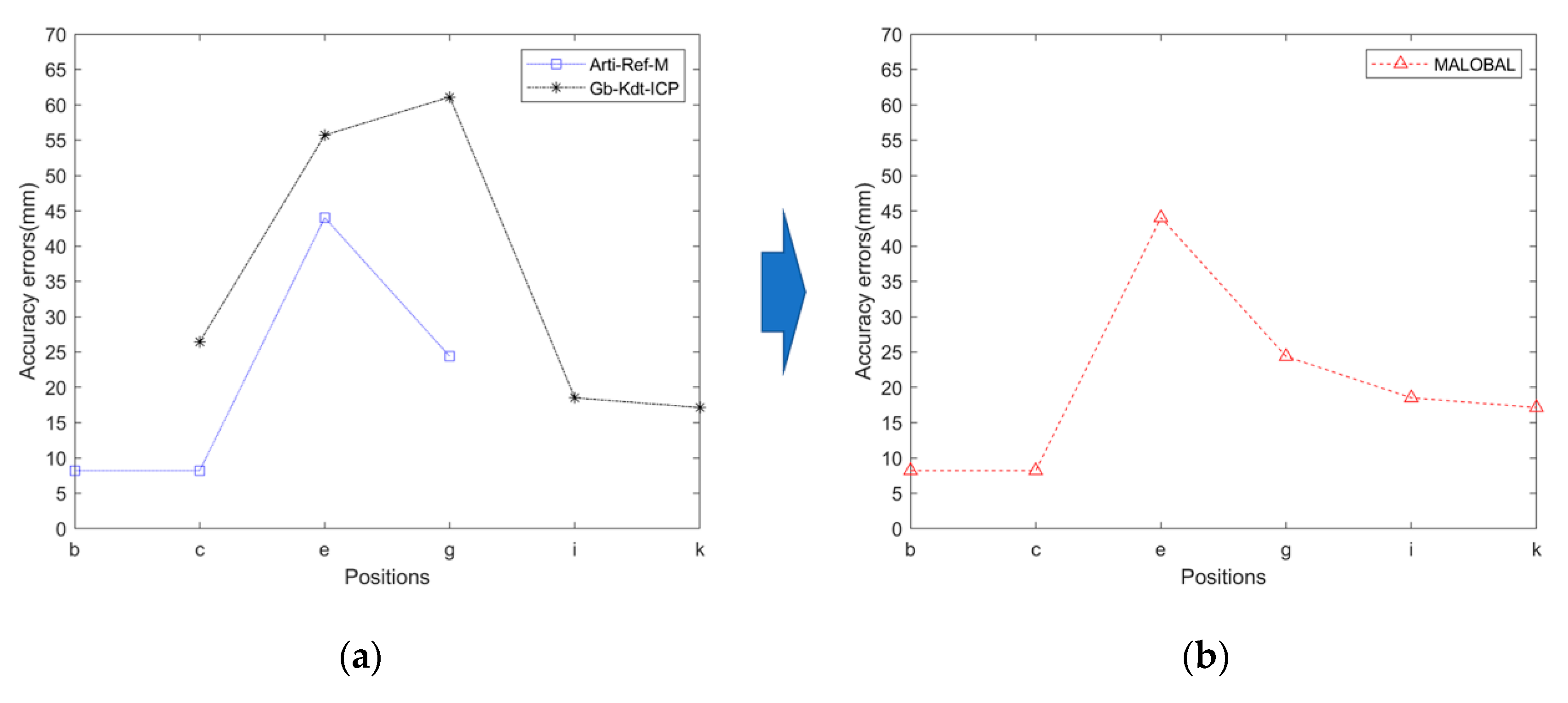
5. Results and Discussion

The chapter compares the All-ICP, All-Kdt-ICP, and Gb-Kdt-ICP methods proposed in the previous chapter. Firstly, the initial location b of mobile robot is determined by the trilateral measurement method, and the geometric primitive features of the ongoing buildings at the adjacent operating positions (such as, location b-c) are extracted to estimate the next operating position c. By analogy, the localization results of mobile robot in 6 working locations are calculated. Comparison results of the three matching methods are shown in Table 2.
According to the matching results of mobile robot at the five working locations in Table 2, the values of mean square error and calculation efficiency that based on three matching methods are obtained, as shown in Figure 9 and Figure 10. Figure 9 shows that the Gb-Kdt-ICP algorithm based on ongoing buildings can achieve better matching results than the methods of All-ICP and All-Kdt-ICP during the matching process of d-e, h-i, and j-k locations. The minimum value of matching mean square error is 17.15 mm. Similarly, in the matching of locations b-c and f-g for mobile robot, the Gb-Kdt-ICP algorithm proposed in this paper performs poorly. It has a larger matching error than the All-ICP and All-Kdt-ICP algorithms. In short, when the number of ongoing buildings in the scene gradually increases, mobile robot extracts the building features of the scene, and the localization error of it is reduced from the working locations h-i-j-k, the localization accuracy of mobile robot is gradually improved. Similarly, from Figure 10, it can be seen that the time-consuming of the All-Kdt-ICP algorithm is 0.052 s, and the Gb-Kdt-ICP algorithm is 0.027 s. Thus, it shows that the Gb-Kdt-ICP algorithm based on the generated buildings that proposed in this paper has a higher calculation efficiency. Compared with the All-Kdt-ICP algorithm, the calculation efficiency of Gb-Kdt-ICP is approximately increased by 2 times. It is more conducive to the localization application of mobile robot in actual scenes.
From above experimental tests, the actual values of mobile robot in the 6 key operating positions are measured, and the measured values are regarded as true values and they are represented by the symbol of T r u . MALOBAL is a hybrid localization method, it is the combination of Arti-Ref-M and Gb-Kdt-ICP methods based on adaptive weighting factors. To realize the robust localization for mobile robot in ongoing scene, the paper adopts a hybrid localization method based on adaptive weightings to balance an overall performance in accuracy and efficiency of localization for mobile robot [24,27]. Then the MALOBAL method is combined with the Arti-Ref-M localization algorithm based on artificial landmarks and the Gb-Kdt-ICP matching algorithm, and the localization error equation of mobile robot is also established at the working locations p i . The specific localization error equation is as follows:
e p i = | T r u p i Γ p i | , p i = 1 , 2 , , 6
Through the comparative analysis, the localization errors in 6 different locations of mobile robot under three working conditions are repeatedly calculated, and the results of localization errors are shown in Figure 11.
According to Figure 11 above, when the mobile robot is at location b, the weighting coefficient W f , s of Lidar’s noise and the weighted coefficient W f , l of measured error are introduced. At this time, the mobile robot can locate itself by identifying the artificial landmarks of the scene and the minimum localization error is 8.22 mm. At the working locations c, e, g, the reflectors and ongoing buildings are both in the scene. The minimum error of localization adopted by the MALOBAL method can be achieved at 8.22 mm, and the maximum error is up to 44.02 mm. In the same way, the minimum localization error of mobile robot is 17.15 mm at the working locations i and k. In summary, the experimental results have shown that the MALOBAL algorithm can adaptively applied into the ongoing scene, which improves the localization accuracy and calculation efficiency of mobile robot, and reflects a better localization with robustness.

6. Conclusions

The paper proposes a hybrid localization method based on two geometric primitives of reflectors and ongoing buildings. In the case of insufficient or missing features of artificial landmarks in the scene, the MALOBAL method provides a novel approach for the on-site prefabricated mobile robot. At the same time, the MALOBAL method can provide high accuracy of localization and calculation efficiency for mobile robot. Compared with adding more numbers of reflectors to improve the robust localization, the MALOBAL method can reduce the economic cost and human intervention time to a certain extent. It also improves the personal safety and operation flexibility of the construction scene, which enables the possibilities for mobile robots to complete scene construction and monitoring automatically. In future work, we plan to apply the MALOBAL method proposed in the paper to the entity of mobile construction robot on site, and use the mainstream SLAM technology with multi-sensor fusion to further improve the robust localization and navigation. In this way, the robust localization method can provide a fast and accurate position for subsequent tasks such as path planning and autonomous exploration and improve the construction efficiency and scene monitoring for mobile construction robots.

Author Contributions

Conceptualization, Z.X. and T.S.; methodology, Z.X. and S.G.; software, Z.X.; validation and investigation, Z.X. and L.Z.; resources, S.G. and T.S.; writing—original draft preparation, Z.X.; writing—review and editing, S.G. and T.S.; supervision, S.G.; funding acquisition, S.G. and T.S. All authors have read and agreed to the published version of the manuscript.

Funding

This research was funded by the National Natural Science Foundation of China (No. U1913603, 61803251, 51775322), by the National Key Research and Development Program of China (No. 2019YFB1310003), and by Shanghai Robot Functional Platform.

Conflicts of Interest

The authors declare no conflict of interest.

References

  1. Ardiny, H.; Witwicki, S.; Mondada, F. Are Autonomous Mobile Robots Able to Take Over Construction? A Review. Int. J. Robot. Theor. Appl. 2015, 4, 10–21. [Google Scholar]
  2. Labonnote, N.; Rønnquist, A.; Manum, B.; Rüther, P. Additive construction: State-of-the-art, challenges and opportunities. Autom. Constr. 2016, 72, 347–366. [Google Scholar] [CrossRef]
  3. Dörfler, K.; Sandy, T.; Giftthaler, M.; Gramazio, F.; Kohler, M.; Buchli, J. Mobile robotic brickwork—Automation of a discrete robotic fabrication process using an autonomous mobile robot. In Robotic Fabrication in Architecture, Art and Design; Springer: New York, NY, USA, 2016; pp. 205–217. [Google Scholar]
  4. Helm, V.; Ercan, S.; Gramazio, F.; Kohler, M. Mobile robotic fabrication on construction sites: DimRob. In Proceedings of the 2012 IEEE/RSJ International Conference Intelligent Robots and Systems, Vilamoura, Portugal, 7–12 October 2012. [Google Scholar]
  5. Gambao, E.; Balaguer, C. Robotics and Automation in Construction. IEEE Robot. Autom. Mag. 2002, 9, 4–6. [Google Scholar] [CrossRef]
  6. O’Brien, J.; Saidi, K.; Lytle, A. Robotics in construction. In Springer Handbook of Robotics; Siciliano, B., Khatib, O., Eds.; Springer: Berlin, Germany, 2008; pp. 1079–1099. [Google Scholar]
  7. Kundu, A.S.; Mazumder, O.; Dhar, A.; Lenka, P.K.; Bhaumik, S. Scanning Camera and Augmented Reality Based Localization of Omnidirectional Robot for Indoor Application. Proc. Comput. Sci. 2017, 105, 27–33. [Google Scholar] [CrossRef]
  8. Paijens, A.F.; Huang, L.; Al-Jumaily, A. Mobile robot positioning system for precision manufacturing: The laser lighthouse revisited. In Proceedings of the 2017 3rd International Conference on Control, Automation and Robotics (ICCAR), Nagoya, Japan, 24–26 April 2017. [Google Scholar]
  9. Pierlot, V.; van Droogenbroeck, M. A New Three Object Triangulation Algorithm for Mobile Robot Positioning. IEEE Trans. Robot. 2014, 30, 566–577. [Google Scholar] [CrossRef] [Green Version]
  10. Pierlot, V.; van Droogenbroeck, M. BeAMS: A Beacon-Based Angle Measurement Sensor for Mobile Robot Positioning. IEEE Trans. Robot. 2014, 30, 533–549. [Google Scholar] [CrossRef] [Green Version]
  11. Easton, A.; Cameron, S. A Gaussian Error Model for Triangulation-Based Pose Estimation Using Noisy Landmarks. In Proceedings of the IEEE Conference on Robotics, Automation & Mechatronics, Bangkok, Thailand, 1–3 June 2006. [Google Scholar]
  12. Huang, Z.; Zhu, J.; Yang, L.; Xue, B.; Wu, J.; Zhao, Z. Accurate 3-D Position and Orientation Method for Indoor Mobile Robot Navigation Based on Photoelectric Scanning. IEEE Trans. Instrum. Meas. 2015, 64, 2518–2529. [Google Scholar] [CrossRef]
  13. Mao, J.; Hu, X.; Milford, M. An adaptive localization system for image storage and localization latency requirements. Robot. Auton. Syst. 2018, 107, 246–261. [Google Scholar] [CrossRef]
  14. Wang, Y.; Chen, W.; Wang, J.; Wang, H. Active global localization based on localizability for mobile robots. Robotica 2015, 33, 1609–1627. [Google Scholar] [CrossRef]
  15. Pomárico-Franquiz, J.; Khan, S.H.; Shmaliy, Y.S. Combined extended FIR/Kalman filtering for indoor robot localization via triangulation. Measurement 2014, 50, 236–243. [Google Scholar] [CrossRef]
  16. Font-Llagunes, J.M.; Batlle, J.A. Consistent triangulation for mobile robot localization using discontinuous angular measurements. Robot. Auton. Syst. 2009, 57, 931–942. [Google Scholar] [CrossRef]
  17. Barczyk, M.; Bonnabel, S.; Deschaud, J.E.; Goulette, F. Invariant EKF Design for Scan Matching-aided Localization. IEEE Trans. Control Syst. Tech. 2015, 23, 2440–2448. [Google Scholar] [CrossRef] [Green Version]
  18. Guo, S.; Yan, Z.X.; Song, T.; Xu, Z.; Zeng, L.D. Improvement of localization with artificial landmark for mobile manipulator. Int. J. Adv. Robot. Syst. 2019, 16, 1729881419862985. [Google Scholar] [CrossRef] [Green Version]
  19. Durrant-Whyte, H.; Bailey, T. Simultaneous localization and mapping: Part I. IEEE Robot. Autom. Mag. 2006, 13, 99–110. [Google Scholar] [CrossRef] [Green Version]
  20. Cadena, C.; Carlone, L.; Carrillo, H.; Latif, Y.; Scaramuzza, D.; Neira, J.; Reid, I.; Leonard, J.J. Past, Present, and Future of Simultaneous Localization and Mapping: Toward the Robust-Perception Age. IEEE Trans. Robot. 2016, 32, 1309–1332. [Google Scholar] [CrossRef] [Green Version]
  21. Huang, B.; Zhao, J.; Liu, J. A Survey of Simultaneous Localization and Mapping. arXiv 2019, arXiv:1909.05214. [Google Scholar]
  22. Besl, P.J.; Mckay, N.D. A Method for Registration of 3-D Shapes. IEEE Trans. Pattern Anal. Mach. Intell. 1992, 14, 239–256. [Google Scholar] [CrossRef]
  23. Jiang, G.; Yin, L.; Liu, G.; Xi, W.; Ou, Y. FFT-Based Scan-Matching for SLAM Applications with Low-Cost Laser Range Finders. Appl. Sci. 2018, 9, 41. [Google Scholar] [CrossRef] [Green Version]
  24. Ma, J.C.; Zhang, Q.; Ma, L.Y. A novel robust approach for SLAM of mobile robot. J. Cent. S. Univ. 2014, 21, 2208–2215. [Google Scholar] [CrossRef]
  25. Gutmann, J.S.; Schlegel, C. AMOS: Comparison of scan matching approaches for self-localization in indoor environments. In Proceedings of the First Euromicro Workshop on Advanced Mobile Robots (EUROBOT ‘96), Kaiserslautern, Germany, 9–11 October 1996. [Google Scholar]
  26. Weber, J.; Jörg, K.W.; Puttkamer, E.V. APR-Global Scan Matching Using Anchor Point Relationships. In Proceedings of the 6th International Conference Intelligent Autonomous Systems, Venice, Italy, 25–27 July 2000; pp. 471–478. [Google Scholar]
  27. Pfister, S.T.; Kriechbaum, K.L.; Roumeliotis, S.I.; Burdick, J.W. Weighted Range Sensor Matching Algorithms for Mobile Robot Displacement Estimation. In Proceedings of the 2002 IEEE International Conference on Robotics and Automation (Cat. No.02CH37292), Washington, DC, USA, 11–15 May 2002. [Google Scholar]
  28. Minguez, J.; Lamiraux, F.; Montesano, L. Metric-Based Scan Matching Algorithms for Mobile Robot Displacement Estimation. In Proceedings of the 2005 IEEE International Conference on Robotics and Automation (ICRA), Barcelona, Spain, 18–22 April 2005. [Google Scholar]
  29. Lv, J.; Wang, Y.; Wu, K.; Dissanayake, G.; Kobayashi, Y.; Xiong, R. Planar scan matching using incident angle. In Proceedings of the IEEE/RSJ International Conference on Intelligent Robots and Systems, Vancouver, BC, Canada, 24–28 September 2017; p. 404. [Google Scholar]
  30. Diosi, A.; Kleeman, L. Laser scan matching in polar coordinates with application to SLAM. In Proceedings of the 2005 IEEE/RSJ International Conference on Intelligent Robots and Systems, Edmonton, AB, Canada, 2–6 August 2005; pp. 3317–3322. [Google Scholar]
  31. Biber, P.; Strasser, W. The normal distributions transform: A new approach to laser scan matching. In Proceedings of the IEEE/RSJ International Conference on Intelligent Robots and Systems (IROS), Las Vegas, NV, USA, 27–31 October 2003; Volume 3, p. 274. [Google Scholar]
  32. Ryu, K.; Dantanarayana, L.; Furukawa, T.; Dissanayake, G. Grid-based scan-to-map matching for accurate 2D map building. Adv. Robot. 2016, 30, 431–448. [Google Scholar] [CrossRef] [Green Version]
  33. Zhang, K.; Gui, H.; Luo, Z.; Li, D. Matching for navigation map building for automated guided robot based on laser navigation without a reflector. Ind. Robot Int. J. Robot. Res. Appl. 2019, 46, 17–30. [Google Scholar] [CrossRef]
  34. Röwekämper, J.; Sprunk, C.; Tipaldi, G.D.; Stachniss, C.; Pfaff, P.; Burgard, W. On the Position Accuracy of Mobile Robot Localization based on Particle Filters Combined with Scan Matching. In Proceedings of the 2012 IEEE/RSJ International Conference on Intelligent Robots and Systems, Vilamoura, Portugal, 7–12 October 2012. [Google Scholar]
  35. Sakin, M.; Kiroglu, Y.C. 3D Printing of Buildings: Construction of the Sustainable Houses of the Future by BIM. Energy Proc. 2017, 134, 702–711. [Google Scholar] [CrossRef]
  36. Turek, W.; Cetnarowicz, K.; Borkowski, A. On human-centric and robot-centric perspective of a building model . Autom. Constr. 2017, 81, 2–16. [Google Scholar] [CrossRef]
  37. Lussi, M.; Sandy, T.; Doerfler, K.; Hack, N.; Gramazio, F.; Kohler, M.; Buchli, J. Accurate and Adaptive in Situ Fabrication of an Undulated Wall Using an on-Board Visual Sensing System. In Proceedings of the 2018 IEEE International Conference on Robotics and Automation (ICRA), Brisbane, QLD, Australia, 21–25 May 2018. [Google Scholar]
  38. Giftthaler, M.; Sandy, T.; Dörfler, K.; Brooks, I.; Buckingham, M.; Rey, G.; Kohler, M.; Gramazio, F.; Buchli, J. Mobile robotic fabrication at 1:1 scale: The In situ Fabricator. Constr. Robot. 2017, 1, 3–14. [Google Scholar] [CrossRef] [Green Version]
Figure 1. Robot modeling and its component parts. (a) Overall framework of mobile robot. (b) Hardware parts of mobile robot. (c) Partial parameters of 2D Lidar.
Applsci 10 06152 g001
Figure 2. Construction of the ongoing scene for mobile robot. (a) Initial state of the mobile robot. (b) Completed state of the mobile robot.
Applsci 10 06152 g002
Figure 3. Localization diagram of mobile robot in the ongoing scene.
Applsci 10 06152 g003
Figure 4. Extraction of reflectors and localization based on the three-sided measurement.
Applsci 10 06152 g004
Figure 5. Robust localization model based on artificial reflectors and ongoing buildings.
Applsci 10 06152 g005
Figure 6. Localization flowchart of mobile robot at locations of ①~⑥. (a) The initial location ① of the ongoing scene; (b) The working location ② with artificial landmarks and ongoing buildings; (c) The working location ③ with artificial landmarks and ongoing buildings; (d) The working location ④ with artificial landmarks and ongoing buildings; (e) The working location ⑤ with artificial landmarks and ongoing buildings; (f) The last working location ⑥ of the ongoing scene.
Applsci 10 06152 g006
Figure 7. Diagram of experimental indoor construction site. (a) The initial working location; (b) the completed site of the ongoing scene.
Applsci 10 06152 g007
Figure 8. Flowchart of localization for mobile robot in ongoing scenes. (a) The initial scene of location a; (b) The ongoing scene of location b; (c) The ongoing scene of location c; (d) The ongoing scene of location d; (e) The ongoing scene of location e; (f) The ongoing scene of location f; (g) The ongoing scene of location g; (h) The ongoing scene of location h; (i) The ongoing scene of location i; (j) The ongoing scene of location j; (k) The ongoing scene of location k; (l) The ongoing scene of last location l.
Applsci 10 06152 g008
Figure 9. Mean-square error results of three matching algorithms.
Applsci 10 06152 g009
Figure 10. Time-consuming results of three matching algorithms.
Applsci 10 06152 g010
Figure 11. Localization errors of mobile robot at different operating locations (b-k). (a) The accuracy errors of two methods of Arti-Ref-M and Gb-Kdt-ICP; (b) The accuracy error of MALOBAL method that proposed in the paper.
Applsci 10 06152 g011
Table 1. The actual measured values of mobile robot.
p i bcegik
x(mm)8868861118135513551118
y(mm)985985985985985985
θ(rad)2.410.840−0.94−2.51−3.14
Table 2. Matching of mobile robot between two adjacent locations.
p i Local Point Clouds of Lidar Global Matching ResultsGlobal Matching Errors
b–c Applsci 10 06152 i001 Applsci 10 06152 i002 Applsci 10 06152 i003
d–e Applsci 10 06152 i004 Applsci 10 06152 i005 Applsci 10 06152 i006
f–g Applsci 10 06152 i007 Applsci 10 06152 i008 Applsci 10 06152 i009
h–i Applsci 10 06152 i010 Applsci 10 06152 i011 Applsci 10 06152 i012
j–k Applsci 10 06152 i013 Applsci 10 06152 i014 Applsci 10 06152 i015

