1. Introduction
1.1. State of the Art
Increasingly, computer-aided-design and computer-aided-surgery (CAD/CAS) systems are being integrated into surgery procedures, especially in pre-operative planning and guided surgery template design. This work describes the validation of a surgical device utilized in the stabilization of the spine.
Spinal arthrodesis, consisting of the fusion of the spine’s segments by implanting titanium rods anchored to transpedicular screws that are inserted into the vertebra passing by the pedicle bone structure, is the most often utilized spinal stabilization procedure [
1]. Nerve roots and main blood vessels surrounding close to vertebras are critical to consider because the impairment of these structures can be fatal to the patient or can cause severe permanent injuries.
Generally, the standard procedure that uses pedicle screws involves: identifying the entry point for the screw; choosing the trajectory based on X-rays and cannulating the pedicle along it; probing with the appropriate device to detect breaches; and tapping and screw introduction.
This procedure is usually performed “hand-based” with all the related aspects that affect confidence in implantology. Even the experienced surgeons sometimes have to correct the trajectory of the screws during surgery. The correct introduction in the vertebra is normally monitored with many harmful radiographic shots [
1].
New navigation systems are normally utilized to allow viewing on a screen, in real time, the anatomical structures to be treated, avoiding dangerous X-ray shots. These systems present three technical issues: positioning accuracy, calibration, and high costs [
1].
For these reasons, patient-specific surgical templates produced in three-dimensional biocompatible material via rapid prototyping technology represent a valid alternative.
Ma [
2] demonstrated that the surgical template improves screw placement precision by comparing the accuracy with and without templates. Kashani [
3] proposed a particular surgical template that could accommodate drill having different diameters.
Normally, during the pre-operative step the identification of the screw direction is performed. The surgical template is designed based on the results of the previous step. A multilevel surgical template was designed, via CAD software, by Merc et al. [
4]. Even though several aspects were automated in this way, multilevel templates did not always guarantee excellent positioning. In [
5], the authors tried to find the smallest diameter of the pedicles. They calculated the optimal orientation and the maximum size of the screws via least squares method. In this case, problems raised for highly deformed spines. A method that finds the isthmus of the pedicles intended as the smallest section and from its centre projects a perpendicular straight line i.e., the optimum direction for the screws was presented in [
6]. In [
7], the authors have shown a computer-aided method for calculating the best path for pedicle screw insertion (sufficiently equidistant from the barycentric points of the pre-set coronal sections of the pedicle), with appropriate dimensioning of the screw based on the smallest cross section of the pedicle. Recently, other researchers [
8,
9] have worked on writing algorithms to find the best trajectories, diameters, and maximum length for screws. In [
10], a new hook-shaped rapid-prototyped template has been tested on a single patient and a comparison with twelve similar techniques presented in previous articles has been performed, demonstrating the accuracy in surgery and the usability of the proposed template. Nevertheless, a real clinical trial has not been conducted on a sufficiently wide sample of cases.
1.2. Aims and Scopes
This paper is focused on the validation of the design of a surgical device, that is opportunely customized for the patient to optimize the lumbar pedicle screws insertion via the CAD-CAS approach and its manufacturing via rapid prototyping techniques. The optimal insertion trajectories, the length, and the diameter of the screws are designed starting from CAD model of the area of interest (insertion area). This model comes from reverse engineering (RE) techniques.
The design of the device starts from the knowledge of the screw entry point that will be chosen by the surgeon based on his experience.
Subsequently, the optimal screw insertion trajectories are determined via a patented algorithm [
8,
11,
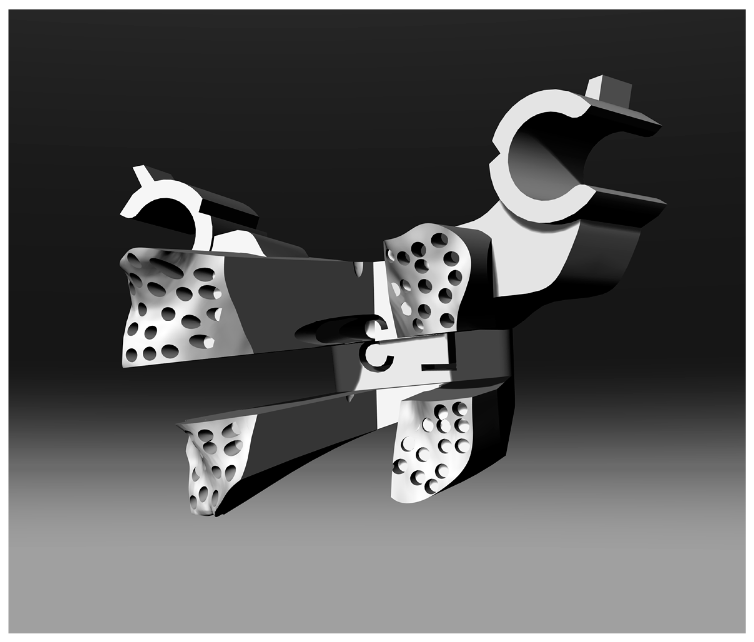
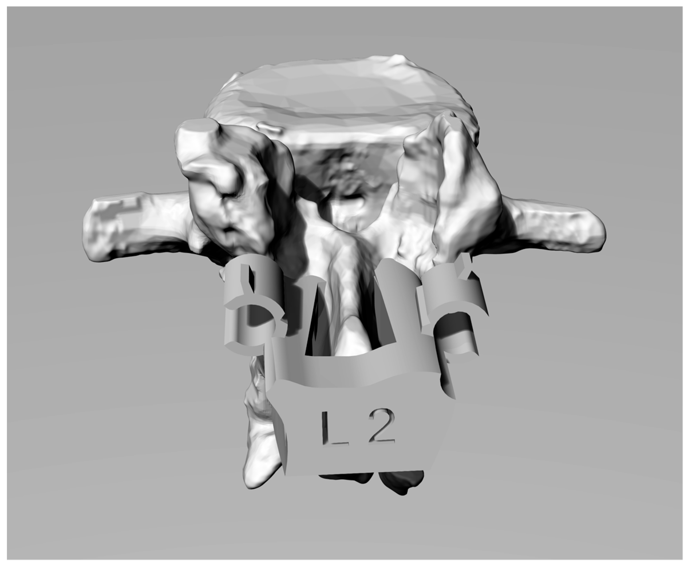
12]. The matching and disengage system presents several innovations. The first consists of the possibility of being able to apply not only pointers and perforators, but also to directly apply pedicle screws that can be used with any surgical instruments. In fact, the guide cylinders are designed to be able to implant different screws with different instruments thanks to a notch that allows the controlled fracture of a portion of the cylinders themselves, facilitating the last phase of screw implantology and the mask removal. An innovative contact surface between mask and vertebra has also been designed with several holes, with a diameter of about half a millimetre, that are arranged randomly on the surface of the mask to increase the probability that any presence of small tissue produced during the skeletonization will be channelled into these holes, thereby avoiding creating interference in the coupling between the mask and the vertebra with possible mismatching.
This template also allows preserving a good portion of the supraspinous longitudinal ligament (when there is no laminectomy) because the anchor points of the template on the vertebra are traceable to four portions of vertebral lamina. Finally, thanks to a semi-automatic trajectory identification algorithm that allows the surgeon to choose the first access point, it is also possible to think about designing the whole template in a semi-automatic way.
The proposed device is used only as a guide that integrates perfectly with the standard freehand surgical procedure without altering it but allowing a guided screw implantology.
In the classical freehand procedure, the radiation doses, surgery time, and risk of error are generally acceptable but high. Moreover, wrong positioning could induce to surgery failure resulting in re-intervention and, normally, an increase in surgery duration that means an increase of noxious real-time X-rays. The proposed surgical device drives surgeon throughout the best insertion direction of the screws, keeping down the risk of damaging the nervous system. Moreover, this procedure cuts down the surgery duration (resulting in an increase in surgery comfort), the blood loss, and radiation doses.
2. Materials and Methods
2.1. Patient Sample
To validate the use of the lumbar drilling template, a clinical trial was performed at San Giovanni di Dio e Ruggi D’Aragona public hospital (Salerno, Campania, Italy). Twenty patients (8 women and 12 men) were enrolled randomly. The patient inclusion criterion was people who were waiting for vertebral stabilisation surgery for degenerative disease of the lumbar spine, including de novo scoliosis, with a maximum age of 70 years and a minimum of 50 years, without home pharmacological therapy.
During the trial, thirty vertebrae were surgically treated by the traditional procedure, and thirty vertebrae were treated using the custom-made template. All vertebrae were in the lumbar spine except for a single patient whose vertebrae T10 and T11 were operated on, respectively, without and with the template.
The segments on which to intervene using the template and on which to proceed in a traditional way were chosen randomly. The comparison between the two approaches took place in the same operative conditions (health status of the patient, presence of staff in the operating room, side effects, etc.).
2.2. Collected Data and Statistics
During the trial, data were collected before, during, and after surgery. An example of the data sheet is included in
Online Resource 1. The complete datasheet is presented in
Online Resource 2.
Both objective and subjective data were collected to perform the comparison with and without the use of the template and to validate the template itself.
Data collected were:
Surgery times:
X-ray shots during single-vertebra surgery;
Kirshner wire positioning error; and
Screw positioning error (requiring a screw repositioning).
Qualitative data were organised in a synoptic table including:
2.3. Patient’s Spine 3D Modelling
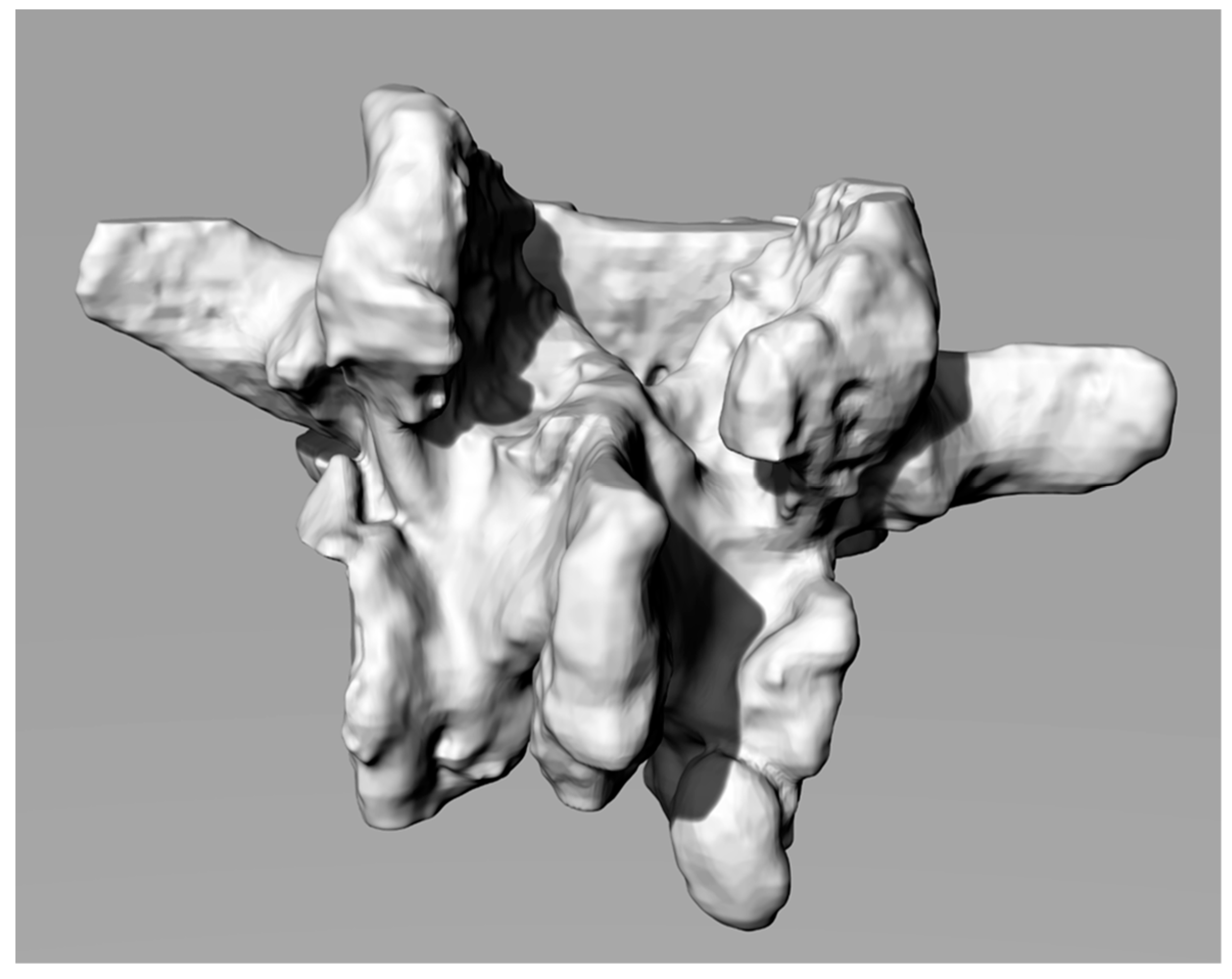
The 3D CAD models of the vertebral bodies were obtained starting with a CT scan that gave a DICOM output. This output was imported in Materialize Mimics software (Materialize NV—Leuven, Belgium) for human structures segmentation, which allows for reconstructions of the lumbar regions with both automatic and manual thresholding techniques, based on the Hounsfield Grayscale.
Segmentation generates 3D Standard-Triangulation-Language (STL) models of the vertebrae that were imported into Geomagic software (3D Systems— Rock Hill (SC), USA) for conversions in poli-surfaces format (IGES). This step is particularly useful because the IGES model is composed by closed surfaces that are suitable for processing with CAD modelling software. After the conversion into IGES format, the vertebral model was imported using the Rhinoceros Software (Robert McNeel & Associates—Seattle, WA, USA).
Figure 1 shows a 3D reconstruction.
2.4. Computer Aided Surgery Planning: Screws’ Optimal Length, Diameter and Insertion Direction
The target of the arthrodesis surgery is to locate the screws. The standard procedure expects a barycentric insertion of the screw with respect to the cross sections of the pedicle and tendentially parallel to the vertebral plate (that is the transverse plane) [
14]. The standard procedure is a freehand empirical method where anatomical landmarks suggest the ideal insertion direction. The target is to find an optimized insertion of the screw from a structural and patient safety point of view, avoiding the “pull out” phenomenon. The trajectories are chosen in order to be properly convergent.
These specifications reduce the probability of damage to spinal, nerve and circulatory structures (especially in the upper part of the vertebral column).
In the proposed procedure, the search for optimal directions is carried out, as previously mentioned, through an algorithm based on a rigorous mathematical method that avoids to define a minimal section of the isthmus, unlike other research works mentioned in the introduction. In this case, in fact, the algorithm defines a free 3D space (whose volume can be safely crossed by a screw without touching the outer pedicle’s surfaces) whose visibility is guaranteed because it coincides with the entry point (visible) chosen by the surgeon. The previous sections describe the innovativeness of this procedure, which includes the innovative trajectory of insertion design in [
8,
12,
15].
The algorithm identifies the available bone space building a solid angle from the entry point located on the surface of the bone. From this point, the algorithm estimates the barycentric trajectories and the acceptable maximum screws’ diameter. Moreover, it calculates the length of the screws based on the distance between the screws’ tip, the vertebra external surface, and the sagittal plane, considering an opportune safety factor (for further details, see [
8,
11,
12]).
2.5. 3D CAD Modelling of the Customized Template
The 3D modelling of the customized template is the crucial step of the methodology; it has to fit perfectly with the vertebra to direct the surgeon correctly during screw insertion.
The spine segment has to be imported into the Rhinoceros® software to check potential interferences between vertebra and the template (during the surgery) while also neglecting the vertebral natural distraction due to excision of the supraspinous ligament (which usually is foreseen in this kind of surgery or is needed in decompressive laminectomy surgery and usually is performed for vertebral distraction) that usually helps avoid interferences.
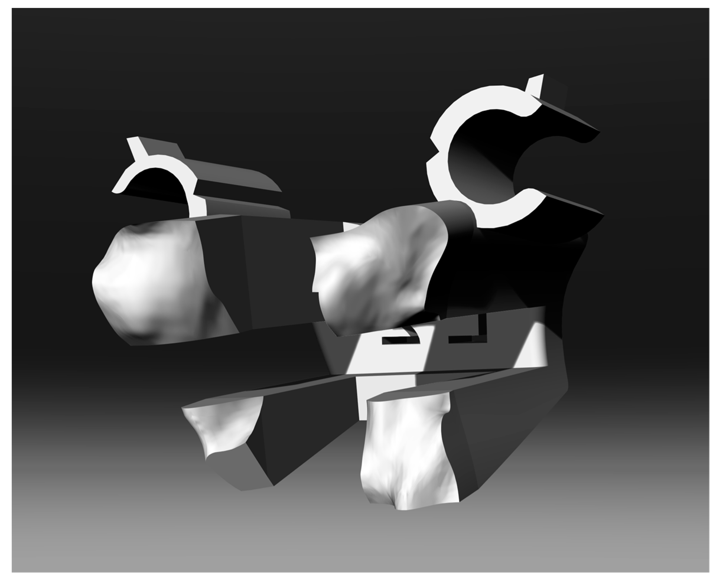
The template interfacing shape is obtained by creating a negative solid from the lamina of the vertebra through a Boolean difference operation between a sufficiently big prism and the vertebra itself. While doing that, the modelling procedure takes into consideration the spinous process to prevent under-cuts that could negatively affect the template positioning.
Therefore, it is appropriate to cut the 3D model of the template in its internal surfaces so as not to generate interference and under-cuts with the surfaces of the spinous process. On the solid, tubes and holes have to be created along the already verified trajectories for creating the guides for the screws.
Figure 2 shows the final shape of the solid.
2.6. Innovative Engaging and Disengaging Device
The surgical operation of “skeletonization” (removing all the soft tissue attached to the bone structure of the vertebra) may generate small scraps of tissue or bone due to an imperfect cut during the skeletonization. To avoid matching problems between the vertebra and the template and to simplify the engagement and positioning of the template itself on the exposed surfaces of the vertebra, some tube structures have been generated on the interface surface of the template (see
Figure 3). It has been verified that very small residual tissues or bone are about half a millimetre in diameter for two reasons: the precision capacity of the prototyping machine, and the hypothesis that any pieces of “waste” tissue larger than this size can be easily identified and removed by hand.
The holes are through-holes where the geometry of the mask allows it and are arranged randomly on the surface (it would have been impossible to define a systematic criterion given that the surfaces are all extremely different from each other) to fit in the free space among the tubes and avoid generating interference in the coupling between the surfaces of the template and those of the vertebral lamina.
In in vivo testing, a pre-notched tube (see
Figure 4) used as Kirschner/screw guide on the template has been designed for simplifying the template disengagement once a screw is inserted. After the insertion of the screw, the surgeon can easily break the pre-notched tube without creating plastic scraps, using the small flat spline on the tube [
16].
2.7. 3D Printing of the Physical Models
Physical models of templates were produced by rapid prototyping (RP) techniques using stereolithography technology (SLA) (Form 2 by Formlabs, Formlabs Inc. 35 Medford St., Suite 201, Somerville, MA 02143, USA).
All the templates used for the trial were manufactured utilizing a biocompatible resin (Dental SG, Class 1 biocompatible resin (EN-ISO 10993-1:2009/AC: 2010, USP Class VI)) that was designed to produce drill guides directly. The templates showed directional pipes having holes properly sized for the insertion of Kirschner wires. Templates’ design and prototyping took about three hours. This value is the mean of the 30 treated cases. The production of 20 different templates on the same printing plate requires 3.5 h thanks to the easily scalability of the rapid manufacturing process.
2.8. Procedure for Using the Template
The target of the template is to improve and optimize the standard vertebral arthrodesis procedure by guiding the screws in the optimal directions.
This is obtained by positioning the template on the vertebral surface. The template must be positioned appropriately on the surface of the vertebra to be treated and, consequently, the template design is aimed at the appropriate choice of the contact surfaces in such a way as to make the positioning univocal and avoid errors.
An accurate skeletonization has to be performed on the vertebral lamina before the positioning of the template. This way a stable match can be obtained making a few and small movements in finding the right position on the vertebra surface (thanks also to the innovative engage system).
To simplify the positioning of the surgical template, a minor distraction will be required of the vertebral bodies via, for example, the supraspinatus ligament excision or the positioning of the patient in a hyperkyphotic position. The anchorage to the vertebra is insured by the perfectly fitting shape of the template.
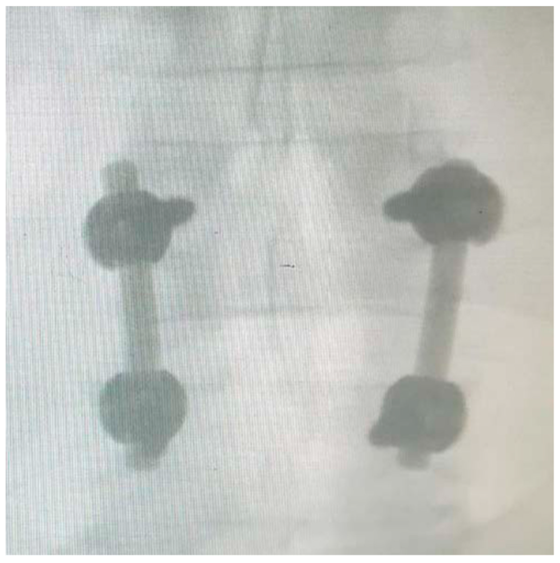
Once verified the template/vertebra coupling, a first X-ray shot has to be done to evaluate the trajectories goodness and theoretical tracing via the Kirschner wires, which are introduced into the vertebral body via the guide tubes and adaptors. Positive X-ray feedback allows the surgeon to directly insert the screw using the direction tubes along the planned direction [
17]. Finally, the surgeon can extract the template by breaking the tongues and disengaging the template.
This procedure has been approved by the Ethical Committee of the Italian Health Ministry.
3. In Vitro Tests
Several in vitro tests were performed to check the feasibility of the templates and the effectiveness of the procedure before beginning the in vivo tests. Several vertebrae belonging to thoracic and lumbar spine segments were acquired by CT (Computerized Tomography) exams and were 3D-modelled and rapidly prototyped in Acrylonitrile-Butadiene-Styrene (ABS) using a fused-deposition-moulding (FDM) technology (Shareboat Dual Extrusor, with a 0.8 mm of thickness and 30 mm/s of print speed) that allows physical models of the vertebrae to be created in a few hours at low cost and with a geometric error lower than 0.3 mm. The procedure was used to build templates to create a physical demonstrator of the surgery. Finally, real screws were inserted in the vertebra utilizing the templates, and the obtained trajectories investigated by simply cutting the vertebra along planned trajectories planes. The results showed the perfect match between planned surgeries and in vitro realised ones.
Clinical Trial: In Vivo Tests
Sixty vertebrae (30 with template and 30 without template), for which a spinal arthrodesis was required, were treated to test the proposed template.
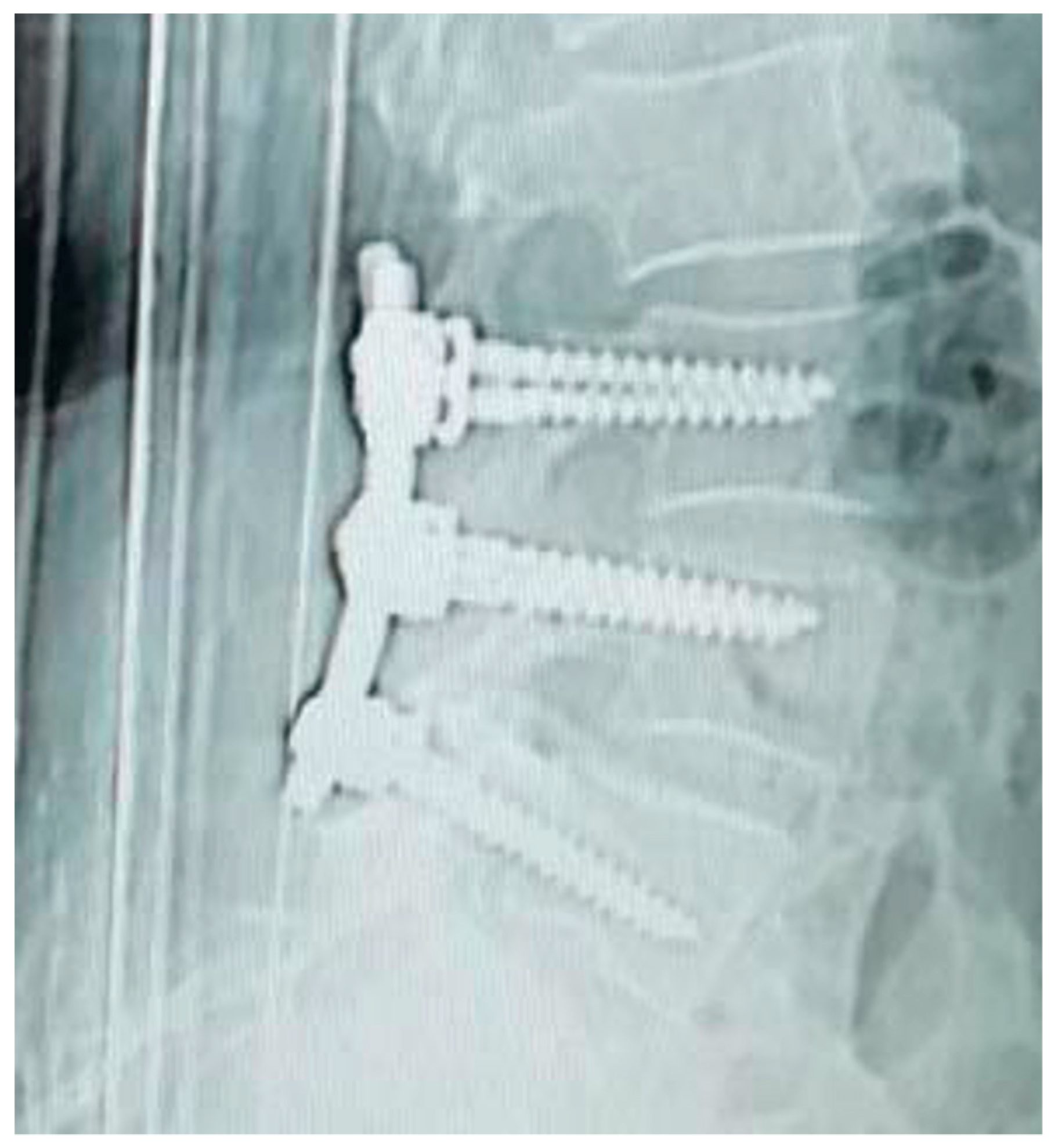
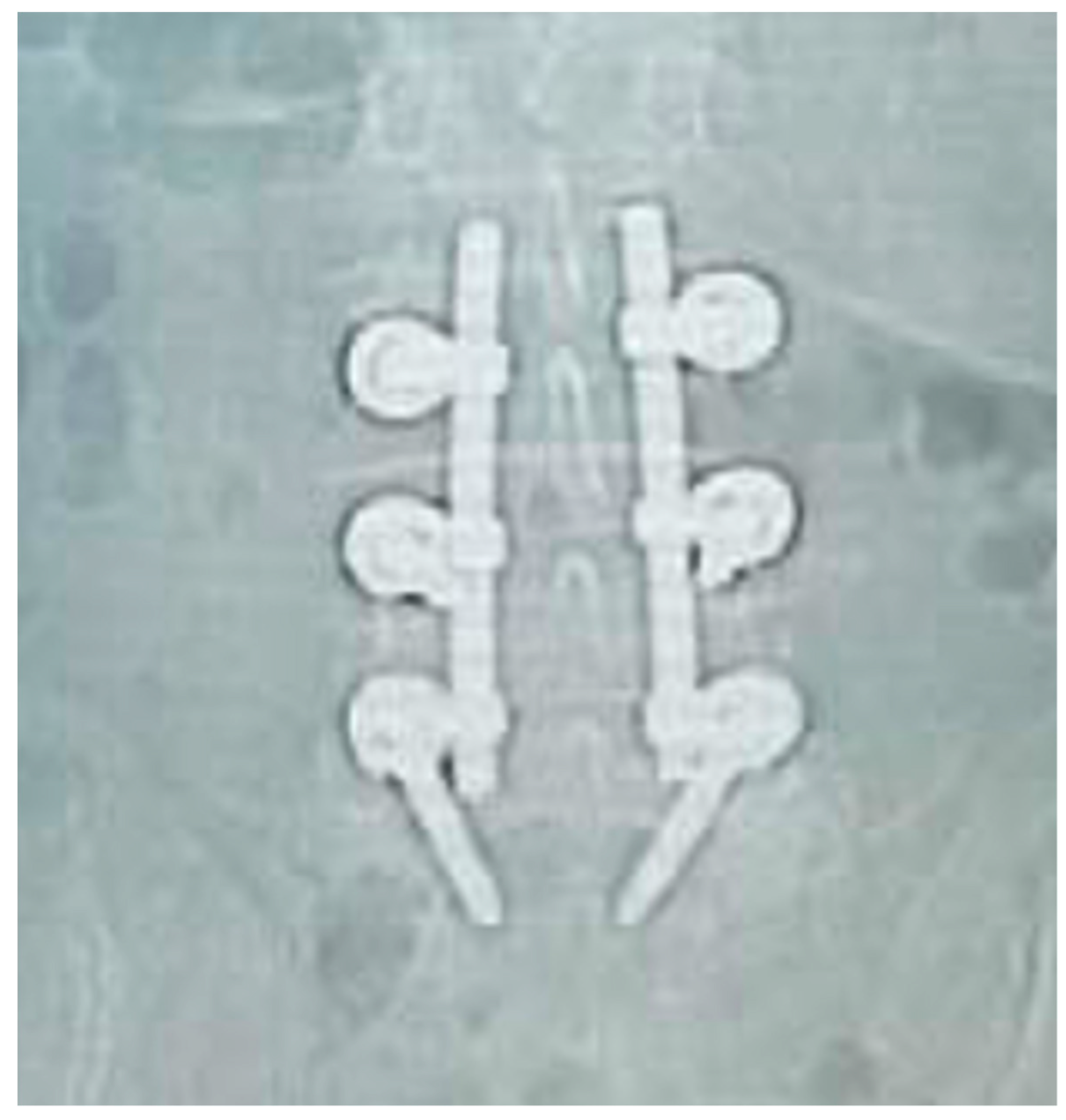
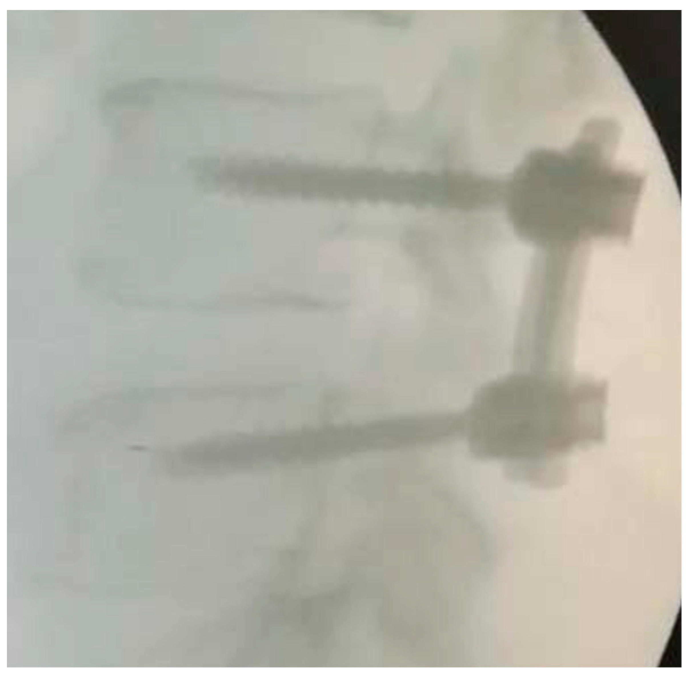
For each pair of screws inserted, an intra-operative X-ray has been taken for evaluating the position of the Kirschner wire and, thereafter, the position of implanted pedicle screws.
Qualitative evaluation parameters: the evaluation of the correctness of the trajectories was expressed by the surgeon based on the good standards present in the medical literature. The X-ray shots were used to provide a good surgery rating.
Quantitative and qualitative evaluation parameters: each screw insertion was evaluated through the following parameters:
accuracy of screw insertion based on three geometrical parameters: centring in the pedicle cross-section, alignment with vertebral plate, screws convergence (the evaluation criterion was class 5 (no violation): the screw is placed along the planned trajectory; class 4 (precise): the screw axis deviates by <2 mm away the planned trajectory; class 3 (normal accuracy): the screw axis deviates by >2 mm but <4 mm away; class 2 (deviated): the screw axis deviates by >4 mm; and class 1 (not conform): the screw axis presents critical deviation);
surgery duration for each vertebra (in minutes);
number of X-ray shots per vertebra (n);
Kirshner wires repositioning times (n); and
pedicle screw repositioning times (n).
All procedures and criteria for the clinical trial were in line with the 1964 Helsinki Declaration, performed in accordance with the ethical standards of current Italian law and approved by the Ethical Review Board of the San Giovanni di Dio e Ruggi d’Aragona University Hospital in Salerno, where the trial/tests were conducted. The trial itself and the proposed procedure have been approved by the Ethical Committee of the Italian Health Ministry (Campania regional district). All participants were informed about the experiment protocol, the nature of the medical implements used, and risks and benefits linked to the new surgical device. Informed consent was signed by the patients.
4. Results
Quantitative comparative analysis with freehand surgery and custom-made template-assisted surgery are synthetically shown in the following tables. Data reported in the tables are mean values among the surgeries. The detailed information about each case treated is reported in
Online Resource 2.
The comparative analysis of the values in
Table 1 shows an improvement of the analysed parameters that is not dependent on the vertebra on which the surgery is done. The improvement is highlighted both in the mean values and in variance. The independence of the results towards the operated-upon vertebra is a strong point of the procedure.
The mean value of X-ray shots, that is, as shown in the table, about equal to 3, is perfectly matching what is required in the procedure: one X-ray shot for template positioning before the vertebra drilling, one X-ray shot for verification of the trajectories during the screw implanting, and the final X-ray shot for verifying the final screw positioning.
Rarely were the Kirschner wires repositioned during the surgery, while the screws were never repositioned (nor for freehand and for guided insertion, probably thanks to the high number of X-ray shots in the freehand cases and to the use of template in the guided cases).
Table 2 shows the comparison of the qualitative data acquired during the surgeries. The surgeon, just after the surgery, was asked to express a motivated judgement on a 5-point scale (1 = very poor, 5 = very good) about the qualitative parameters, just analysing the post-operative X-ray or CT.
The comparison shows a mean value of improvement of the judgements equal to 10%. The reference value is the best judgement the surgeon expressed on the manual insertion.
To check the significance of results of qualitative comparison, a Wilcoxon signed-rank test was performed on the qualitative data: pedicle centring, alignment, and screw convergence. The Wilcoxon test is appropriate because it is a nonparametric test designed to evaluate the difference between two treatments or conditions when the samples are correlated.
The data considered for the two test cases were the case “with template” and the case “without template”.
Table 3 shows the comparison results for two non-null hypotheses:
p-value < 0.01 and
p-value < 0.05.
No significant differences were found among those data except for the case of screw convergence that was checked as significantly better (p-value < 0.05) in the case “with template”.
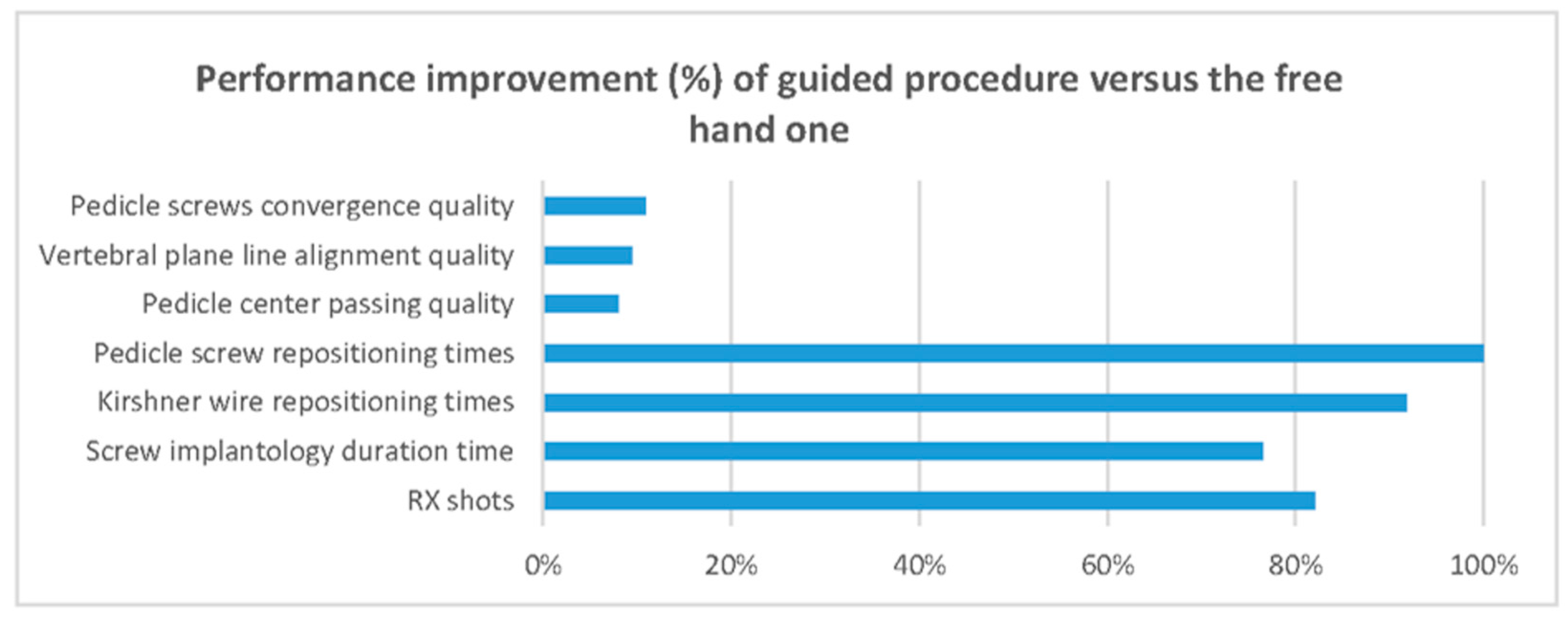
Table 4 synthetises the percentage of improvement of each acquired data point (quantitative and qualitative) without considering the type and level of the vertebra.
Figure 5 also synthetically shows how the use of the surgical template allows improvement of every analysed parameter.
5. Discussion and Perspectives
The standard freehand procedure for pedicle screw insertion is normally characterized by a long learning curve, and the success of the surgery depends on the surgeon’s experience. The surgical device presented is an aid that optimizes the standard procedure. Under this point of view, it becomes an alternative to the very expensive navigation systems that involve additional personnel and equipment.
A patented algorithm finds optimal insertion directions and defines length and diameter of the screws based on a custom-made CAD model, obtained via RE. In order to avoid incorrect relative positioning between the template and the vertebra surface, the proposed template features a novel shape that makes its placement univocal and comfortable for the surgeon. An innovative contact surface between template and vertebra has been designed improving the coupling between the template itself and the vertebras, avoiding possible mismatching. Moreover, the device is designed to disengage the template from the bone surface, making it completely innovative.
The production of a 3D-printed template takes, on average, 1.5 man-hours using the RP machine. Since the template design is based on the use of a patented algorithm [
11,
12,
15], the authors are already working on a modelling system that will allow the semi-automatization of the template design based on the 3D model of the spine. Nevertheless, the surgeon will continue to interact with template designers in order to explain to them his/her preferences about the entry point (for which the surgeon remains responsible) and the template’s size and anchorage.
This device, which gives the surgeon the optimal screw trajectories and provides information regarding the length and diameter of the screws, significantly reduces the risk that the screws get out of the vertebra surface, damaging the vascular and/or the nervous system, and at the same time risking to fracture the bone. Moreover, the duration of the arthrodesis surgery is significantly shortened. Accordingly, the patient’s bleeding, the quantity of drugs, as well as the staff members’ stress levels, are significantly reduced. There is also an important reduction of the harmful X-rays.
For this type of research, it is important to highlight the percentage reduction of both the average insertion time for a single screw and the corresponding number of X-ray shots, measured with and without the surgical guide.
The averaging of the results of interest taken from the surgeries are shown below:
Standard procedure (no template): 27 min for the insertion of one screw and a total of 25 X-rays shots per screw;
Novel procedure (with template): 10 min for the insertion of one screw with the aid of the template and 2 X-rays shots per screw.
The proposed novel device is experimental, and so the duration of the surgeries has been stretched, since the surgeons involved have payed closer attention to a procedure that was somewhat unfamiliar. Anyway, surgery execution times fell within the range stipulated by the Lazio region local health trust [
18].
The use of the proposed novel device achieved improvements in terms of precision, duration and safety, even though the surgical procedure remained the same.
The procedure itself and the use of templates showed some limitations that can be highlighted as the limitation of the study. First of all, the use of templates needs for excellent bone skeletonization of the interface area of the surgical template; in positioning and use of the template, the support of a second staff unit is preferable to ensure that the template is kept in position; nevertheless, surgeons are used to having secondary staff to help the surgery. In order to avoid any kind of mismatch or error in surgery, the surgical template cannot be used if the surgeon wrongly removes part of the bone or if the ligaments to be removed are calcified (not detectable by X-ray). In those cases, the standard procedure has to be performed. This aspect is a limitation, but is also a safety-exit for surgeons who, in case of error, have no problem continuing and completing the procedure by using their standard knowledge and practice.
Finally, the proposed procedure cannot be used for emergency surgeries, as it takes time for 3D reconstruction and redesign.
6. Conclusions
This paper is focused on the design of a novel custom-made surgical template for the optimization of pedicle screw insertion during arthrodesis surgeries. The design is based on both RE and RP techniques, but the surgeon remains responsible for choosing the entry point of the screws.
To summarize briefly, the time spent on the insertion of pedicle screws via the proposed surgical template was cut down by about 63%, while the number of X-ray shots was reduced by about 92%. Precision in surgery outcomes was the same or higher in all of the tests performed.
Future developments will concern the treatment of more complex vertebral shapes. These will entail the introduction of innovative devices for anchoring the surgical template on the vertebra. A new trial has been planned to surgically treat cases with hard scoliosis.
Finally, the template approach will allow a new methodology to be developed for mini-invasive template-based surgery that will bring new methods for percutaneous approaches.
