Article

Finite Element Analysis of the Stress Field in Peri-Implant Bone: A Parametric Study of Influencing Parameters and Their Interactions for Multi-Objective Optimization

1
Université de Lorraine, CNRS, Arts et Métiers, LEM3, F-57000 Metz, France
2
Department of Periodontology and Implantology, Faculty of Dentistry, School of Surgery Nancy Lorraine, F-54000 Nancy, France
3
Université de Lorraine, CNRS, IJL, F-54000 Nancy, France
*
Author to whom correspondence should be addressed.
Appl. Sci. 2020, 10(17), 5973; https://doi.org/10.3390/app10175973
Submission received: 3 August 2020 / Revised: 18 August 2020 / Accepted: 22 August 2020 / Published: 28 August 2020
(This article belongs to the Special Issue Implant Dentistry)

Abstract

:
The present work proposes a parametric finite element model of the general case of a single loaded dental implant. The objective is to estimate and quantify the main effects of several parameters on stress distribution and load transfer between a loaded dental implant and its surrounding bone. The interactions between them are particularly investigated. Seven parameters (implant design and material) were considered as input variables to build the parametric finite element model: the implant diameter, length, taper and angle of inclination, Young’s modulus, the thickness of the cortical bone and Young’s modulus of the cancellous bone. All parameter combinations were tested with a full factorial design for a total of 512 models. Two biomechanical responses were identified to highlight the main effects of the full factorial design and first-order interaction between parameters: peri-implant bone stress and load transfer between bones and implants. The description of the two responses using the identified coefficients then makes it possible to optimize the implant configuration in a case study with type IV. The influence of the seven considered parameters was quantified, and objective information was given to support surgeon choices for implant design and placement. The implant diameter and Young’s modulus and the cortical thickness were the most influential parameters on the two responses. The importance of a low Young’s modulus alloy was highlighted to reduce the stress shielding between implants and the surrounding bone. This method allows obtaining optimized configurations for several case studies with a custom-made design implant.

1. Introduction

Nowadays, the endo-osseous screw dental implant is the most implanted medical device, for which success relies on osseointegration at the bone–implant interface. This biochemical reaction between the metallic part and the bone is achieved by titanium biocompatibility, highlighted for the first time by Pr. Brånemark [1]. Its surgical procedure is completely controlled, ensuring a success rate exceeding 90% [2]. Dental implants placing configuration mainly depend on the geometrical configuration and placement choices of clinicians. It takes into account a lot of criteria. The prosthetic project and the anatomy of the patient appear to be the most essential ones. However, mechanical criteria are rarely considered. They have to be developed to increase the success rate of implantation especially in complex physiological configurations.
The numerical mechanic allows, especially through the Finite Element (FE) method, determining loading levels in considered materials. Over the past two decades, numerous numerical studies have investigated the impact of an endo-osseous dental implant on the surrounding peri-implant bone. Each study focuses on particular parameters under different numerical assumptions by observing different types of results. Certain parameters are commonly used, especially those that describe the geometry of the implant, such as its diameter [3], length [4], taper [5] or threads [6]. General trends can be identified. The diameter and the length, which are the most studied variables, both strongly impact the mechanical environment of the peri-implant bone. It has been shown that a larger length reduces stress in the bone but not as much as a larger diameter [7]. The placement of the implant in the bone is also frequently studied, and some papers have considered its insertion depth [8] or inclination in the bone [9]. For example, it has been found that, the deeper the implant insertion, the more the peri-implant cortical bone is loaded and could be damaged. Bone anatomy is also a parameter often taken into account in numerical models through different modelling approaches. The geometry of the bone and its resorption can be determined from a CT scan [10,11], but the comparison between these studies is limited since they deal with different cases of atrophy. The other widely used approach is to model several thicknesses of cortical bone corresponding to different levels of resorption [12]. Their results converge and lead to the same conclusion that the peri-implant bone is considerably more solicited with a thin cortical thickness. This variable is commonly combined with the characteristics of the bone material, where different moduli of elasticity of cortical or cancellous bone are considered, representative of atrophy levels [13]. These studies showed that the maximum stress in the peri-implant bone increases when the bone Young’s modulus decreases. More rarely, the material of the dental implant is studied. The two most commonly used materials are Ti-6Al-4V alloy [14] and zirconia [15]. Finally, other parameters that relate to numerical modelling assumptions have also been considered in the literature. Interactions and contacts between the different subparts of the models allow, for example, consideration of levels of osseointegration between the implant and the bone [16]. Regardless of the method used to model the interaction, reinforced contact results in better homogeneity and reduced stress in the bone.
A more exhaustive list of studies on this topic is presented in Table 1, ordered by type of parameter studied. In general, papers focusing on similar variables lead to similar conclusions. To our knowledge, only a few studies compare the influence of several parameters. Thus, the results are not meaningful if all variables are not taken into consideration. The present study proposes to build a parametrized model to consider several variable parameters and to compare their influences following the same framework. Seven parameters are assessed, for a total of 512 FE models, taking into account the implant geometry, the implant material and the quality of the implanted bone. The models are compared through two biomechanical responses highlighting the effect of parameters on stress distribution. The main effects and first-order interactions between the parameters on the mechanical environment of the bone are evaluated. Based on the obtained results, the geometrical configuration of implant placement is optimized for a study case with type IV significant bone resorption.

2. Material and Methods

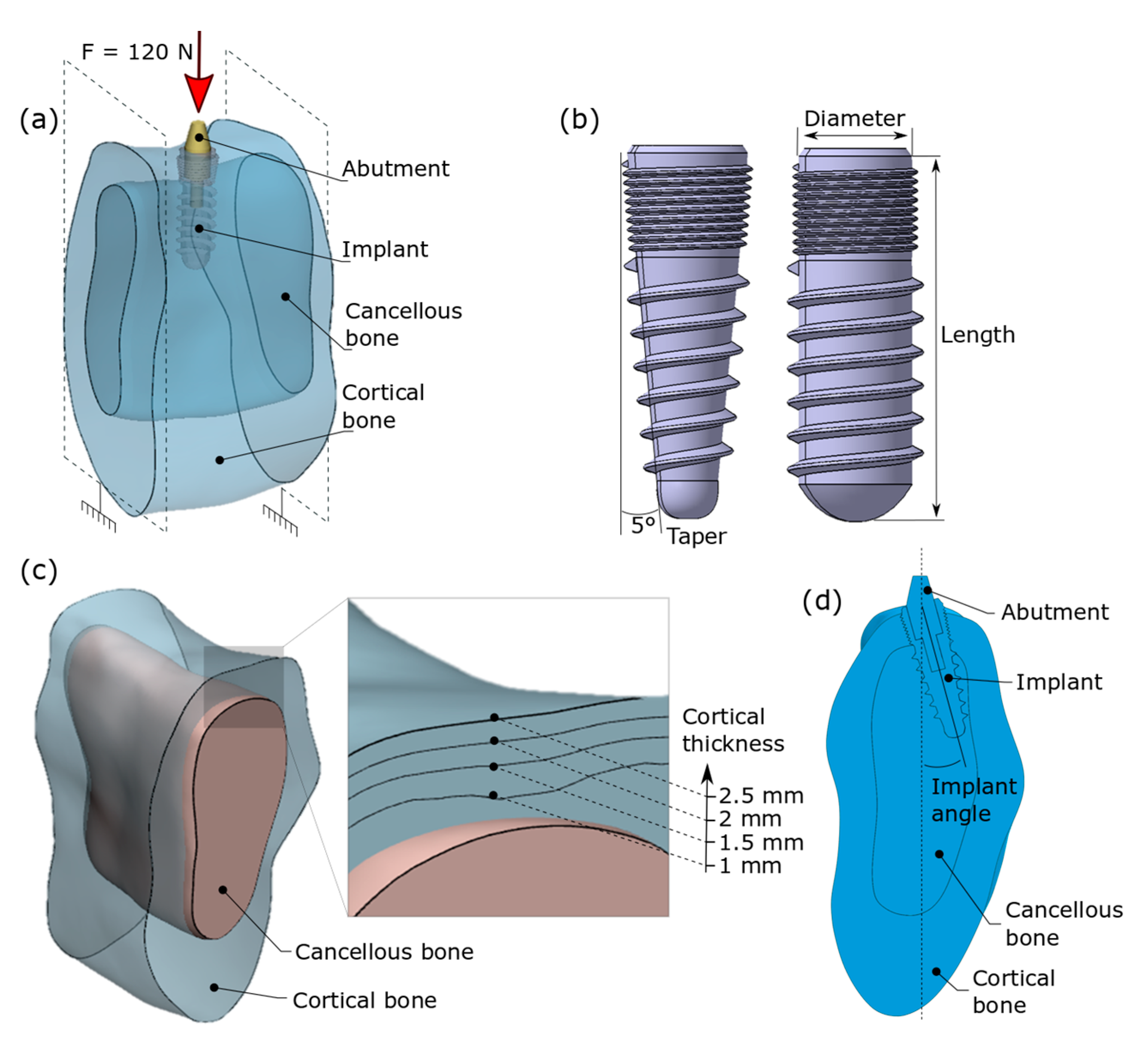
2.1. Presentation of the Finite Element Parametrized Model

To build finite element models automatically with different geometric configurations, a specific numerical strategy was defined. The models are composed of an implant, its abutment, the cortical and the cancellous bone; see Figure 1a. The developed numerical chain is composed of three steps. Firstly, the geometry of the implant, the abutment, the cortical and the cancellous bone are defined. Different design strategies are used for each part. The implant is designed using CATIA V5R20 (Dassault System) with the possibility of varying the length, the diameter and the taper. An example of conical and cylindrical implant design is presented in Figure 1b. The cancellous and cortical bone geometries are generated by segmentation using Mimics (Materialise) from a DICOM (Digital Imaging and Communication in Medicine) file obtained by a CT scan. A 20-mm wide section at the insertion of the first and second premolars is extracted. The geometry of the cancellous part is fixed. To have different thicknesses of cortical bone, a scale factor is applied to the cortical part. In total, four cortical configurations are defined corresponding to four different cortical thicknesses (1.0 mm, 1.5 mm, 2.0 mm and 2.5 mm); see Figure 1c. The second step of the numerical strategy is about assembly of the different parts together. It allows configuration of the placement of the implant in the bone and its angle in the vestibulo-lingual plane; see Figure 1d. The parts are meshed with tetrahedral quadratic elements, with a 0.1-mm average mesh size for a 300,000 tetrahedral average number of elements per model. To finish, boundary conditions, load and materials are set up. The elastic behaviour of the assigned materials is summarized in Table 2. Tied contact is adopted for each interaction. The cross-sectional surfaces of cortical bone and cancellous bone are embedded. A force of 120 N is applied on the top surface of the abutment; see Figure 1a. Whatever the configuration of the model, the direction of the load corresponds to the axis of the implant when it is not inclined.

2.2. Full Factorial Design

A factorial design methodology is used in this study. It aims to analyse the existing relationships between the studied quantities (responses) and their sources of variation (factors or parameters), through a Taylor–Mac Laurin series limited development (Equation (1)). The analyses have been conducted for two responses (Y). The two chosen responses are detailed in the following Section 2.3. The overall average of a response is represented by the parameter b0. Xi represents the investigated parameters, bi corresponds to the main effect and bi-j corresponds to the first-order interaction between two parameters. The purpose of the full factorial design is to determine the most influencing parameters. The developed numerical strategy presented in Section 2.1 allows variation of seven parameters. The diameter, the length, the taper, and the Young’s modulus of the implant and the cancellous bone are 2-level parameters, and the implant angle and the cortical thickness are 4-level parameters. The levels of the studied parameters are summarized in Table 3. A full factorial design is implemented with all possible 512 configurations (25 × 42). All 512 FE models are generated using Abaqus, and the calculations are performed on a high-performance computer with 8 cores.
The full factorial design allows for calculation of the effect of different parameters on the responses. For each response, the main effect of the parameters is determined by the difference between the partial average over the models by setting a studied parameter and the overall average b0. The first-order interactions between the parameters two by two are also calculated by the differences between the partial average performed on the models by setting two studied parameters and the overall average. Quantification of the main effects and first-order interactions makes it possible to describe the response Taylor–Mac Laurin series limited development, where the original variables are translated into reduced centred variables (between −1 and 1).
Y = b 0 +   i b i   X i +   i ,   j b i j   X i   X j

2.3. Two Investigated Biomechanical Responses for Model Classification

Two biomechanical responses are considered through the full factorial design. Response 1 is the first investigated response, defined by the average of Von Mises stress in the peri-implant cortical bone. The implant significantly affects the stress field in relation to a physiological state, and the most loaded bone area is around the neck of the implant [7]. Its deterioration is one of the main causes of dental implant failure [65]. An example of stress distribution in the vestibulo-lingual plane is shown in Figure 2a. Response 1 is calculated through a virtual area corresponding to a concentric cylinder to the implant (7-mm diameter). The average of Von Mises stress is calculated from all nodes of the mesh elements belonging to this peri-implanted area; see Figure 2b.
Response 2 focuses on the load transfer between cortical bone and implant, related to stress-shielding problematic and micromovements at the interface [66]. This response reflects a discontinuity at the bone-implant interface and is assessed by calculating a stress jump along the bone-implant interface. This consists of subtracting average stress from all nodes of the implant mesh from the average stress of the nodes of the cortical bone along the surface.
These two responses are complementary and give an overall view of the biomechanical effect of the 7 investigated parameters, highlighting problems encountered in surgery that impact the life duration of implants. Since these answers are scalar values, it becomes easy to analyse the results and to compare the models to each other through a full factorial design to assist in selecting the most appropriate choice of implant for a given physiological configuration.

2.4. Case Study: Optimization of Implant Placement in Type IV Bone

In the last part of the study, the bone parameters were fixed to define a case study similar to a type IV bone [67]. Other parameters varied and had to be optimized. The parameters of cortical bone thickness and Young’s modulus of cancellous bone were set at 0.5 mm and 0.75 GPa, respectively. The initial factorial design was thus simplified to consider only the five parameters of the implant (diameter, length, taper, angle and Young’s modulus). The coefficients of the main effects and first-order interactions, the identification of which was described in Section 2.2, allow both responses to be described.
The problem has two objective functions and five variables. It has already been shown that the stresses in the peri-implant bone around the implant and the stress jump were significantly higher than in the physiological situation without a dental implant [68,69]. The adopted objective is therefore to minimize both objective functions corresponding to these two responses. The optimization was performed on Matlab software using a genetic algorithm of the NSGA-II type [70]. The search space for solving the problem corresponded to the initial range of variation of the variables.

3. Results

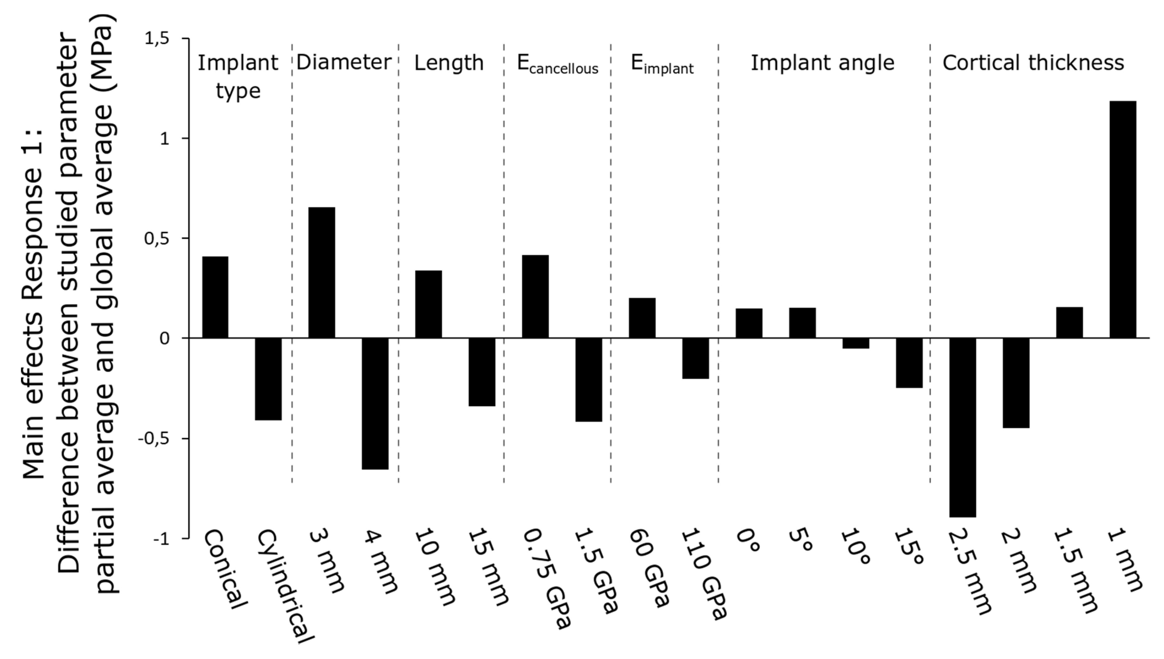
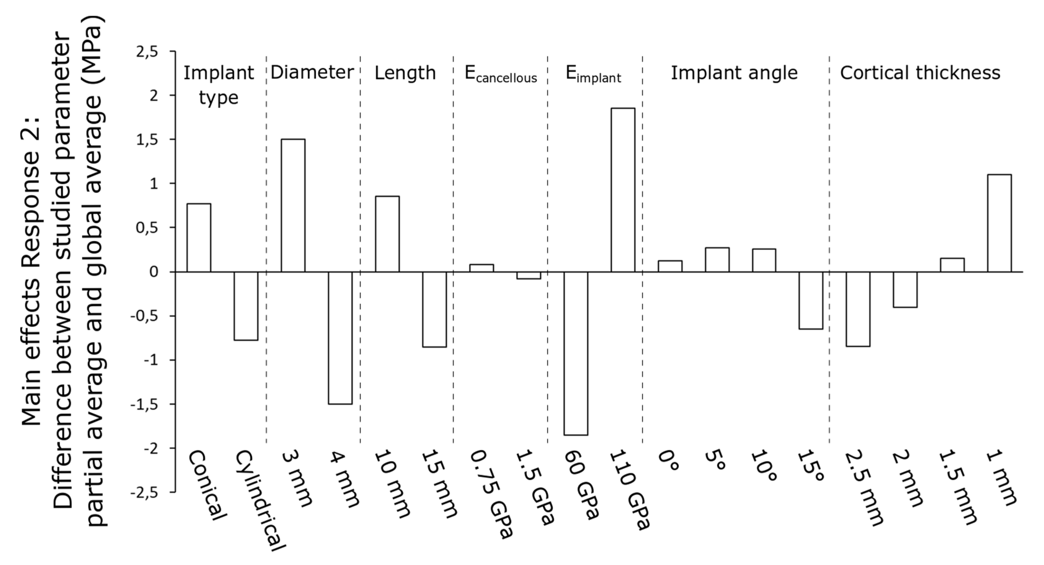
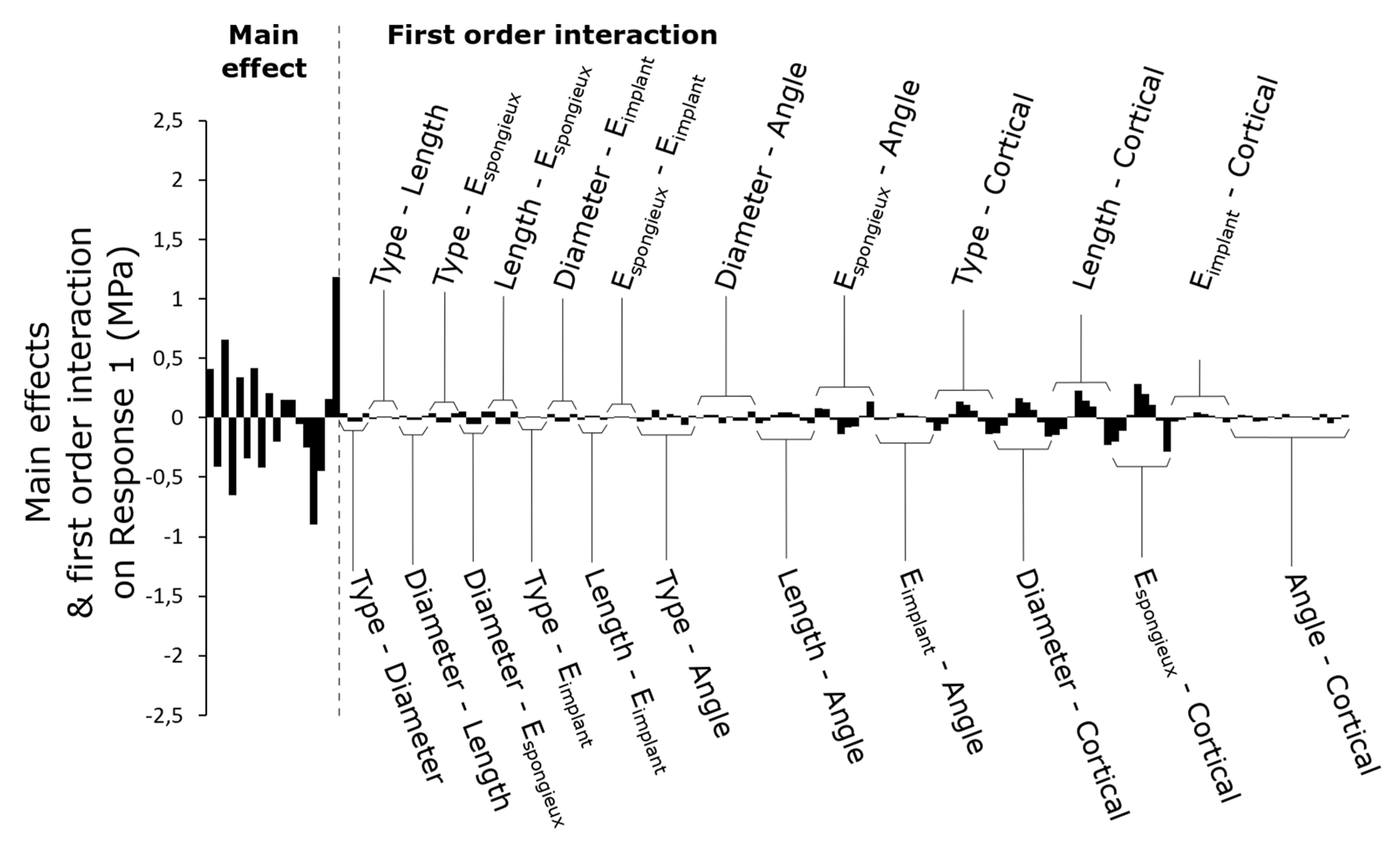
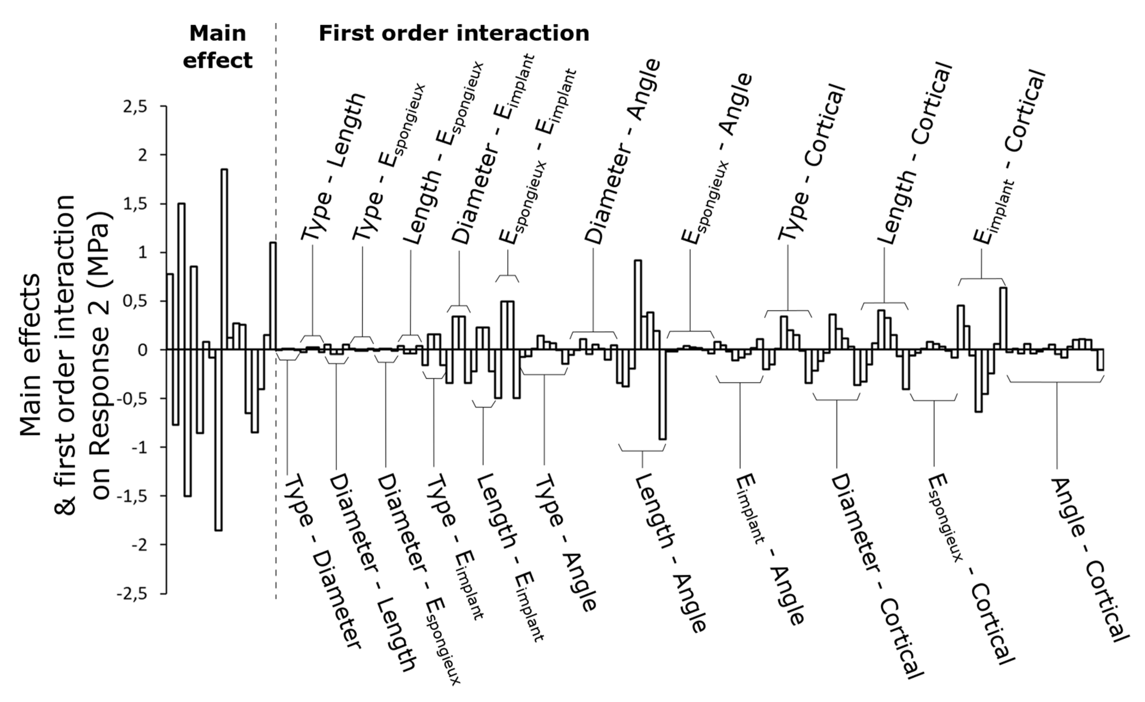
3.1. Main Effects of Parameters

The main effects of the parameters for Response 1 (average stress in cortical peri-implant bone) are summarized in Figure 3. The null effect corresponds to the overall average of this response of the factorial design. Cortical bone thickness is the most influential parameter in the system, and a thickness of 1 mm significantly increases the average stress in cortical bone. Implant diameter is also an influential parameter, even if its range of variation is small (only 1 mm). A large diameter significantly reduces the average stress in the bone. Taper, Young’s modulus of the cancellous bone and length have significant effects on cortical bone, even if they are less than the previous ones. Finally, the Young’s modulus of the implant and its angle of inclination show limited influence on cortical bone compared to other parameters.
The results are different when Response 2 (stress jump between bone and implant) is considered; see Figure 4. Young’s modulus of the implant has the greatest impact on this response, and a lower Young’s modulus significantly reduces the stress jump between the implant and the cortical bone. This parameter became crucial for stress jump when it had little influence on average stress in the bone. The parameters that characterize the implant geometry (diameter, length and taper) are also influential, especially diameter. Cortical bone thickness has less effect on this response compared to other parameters but is still nonnegligible. Finally, Young’s modulus of the cancellous bone and the angle of inclination of the implant have almost no influence on Response 2.

3.2. First-Order Interactions between Parameters

The full factorial design allows for determination of the first-order interactions between parameters. Figure 5 shows 154 coefficients that describe all influences on Response 1, including the main effects and the interactions. Globally, the interactions between implant parameters have less influence on the response than the main effects. Interactions between the different implant geometry parameters are minimal. Notable interactions are those between implant geometry parameters (type, diameter and length) and cortical bone thickness. For example, the smaller the thickness of the cortical bone, the greater the influence of the implant diameter on stress. The most dominant interaction was between cortical bone thickness and cancellous bone modulus. The interaction between implant angle and the Young’s modulus of the cancellous bone was also slightly significant.
Considering Response 2, several interactions have a high influence, as shown in Figure 6. Compared to the main effects, these interaction effects have a greater influence on this response than Response 1. First of all, the interactions between the geometrical parameters of the implant and its Young’s modulus as well as the interaction between the Young’s modulus of the implant and the bone parameters emerge. In addition, as with Response 1, the interactions between implant geometry and cortical thickness are also important. Finally, the interaction between implant length and implant angle can be highlighted.

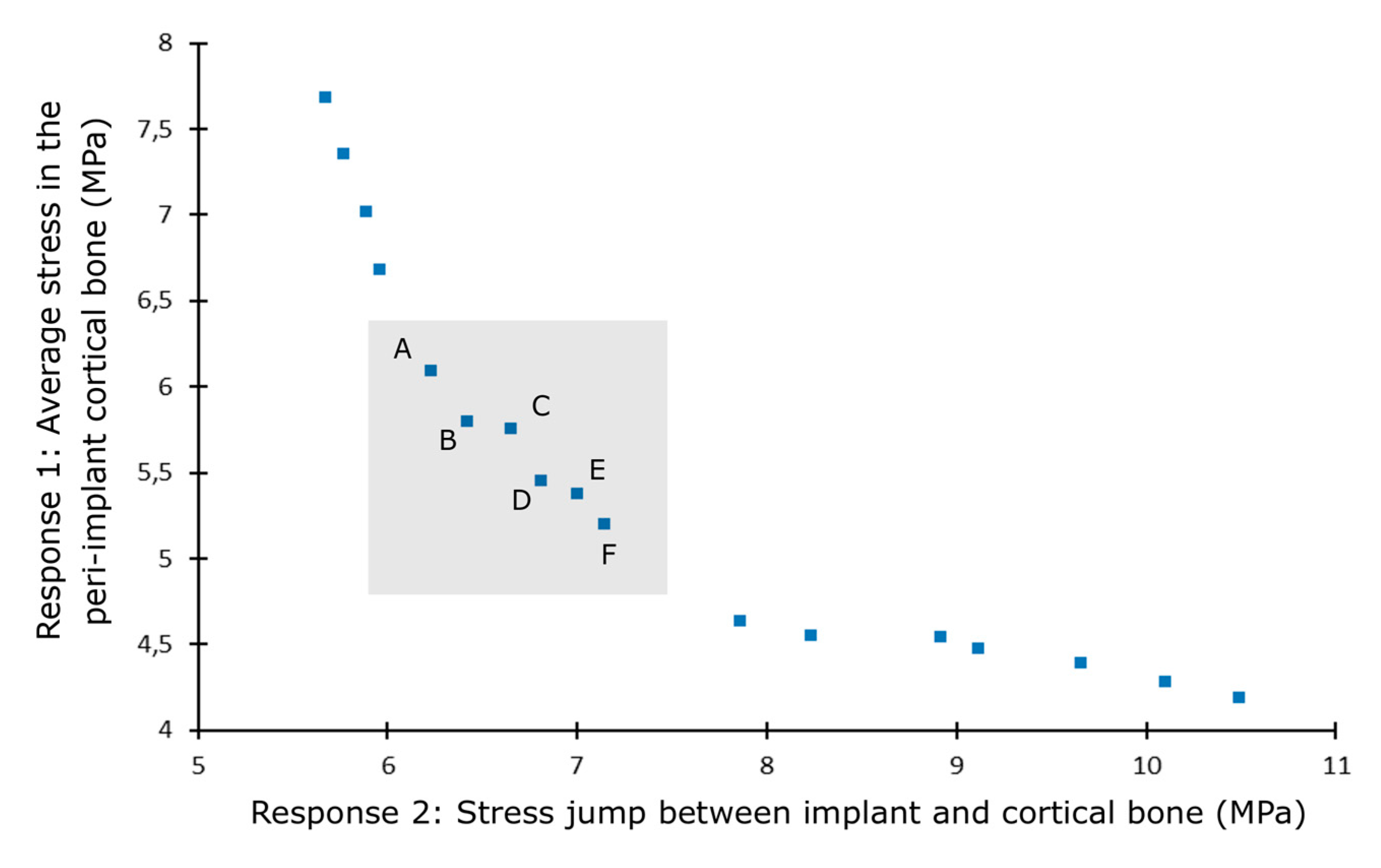
3.3. Case Study: Optimization of the Placement of a Dental Implant in Type IV Bone

The optimal solutions minimizing both Response 1 and Response 2 are presented in Figure 7. The parameter values for the six best configurations are specifically detailed in Table 4. These optimal solutions converge on the choice of specific parameter values. It should be noted that the Young’s modulus of the implant is minimized for all configurations. The length parameter also tends to one of its extremes. A maximum length of 15 mm allows both types of response to be minimized. The variation in diameter is small between the solutions, and optimums are obtained for diameters close to the upper limit of 4 mm. These results are in agreement with the preliminary results of the multiparameter study which recommended a larger diameter to minimize the stress field in the cortical bone. The remaining differences between the solutions, therefore, seem to relate to the taper variable and the angle of inclination of the implant. The taper parameter varies from a quasi-cylindrical implant (solution A) to a slightly tapered implant (up to 2.5°) (solutions E and F).

4. Discussion

4.1. Full Factorial Design

For Response 1, the cortical thickness parameter is predominant over the others. Lower cortical bone thickness causes a very significant increase in stress in the peri-implant bone. Its impact is almost twice as great as that of the implant diameter, the second most influential parameter. The implant diameter is therefore decisive compared to other parameters, whereas its range of variation is only 1 mm. For Response 2, Young’s modulus of the implant is the most influential. A physiological situation in terms of material elasticity is approached when it becomes lower. The implant diameter is also predominant in this second response. The stresses in the implant are lower with a larger diameter, resulting in a decrease of the stress jump between the bone and the implant. The same trend can be seen with the length parameter but is less marked.
The interactions between two variables have weakly been studied and the ranking of so many interactions has never, to our knowledge, been done before. Strong interactions were found between the geometrical parameters of the implant coupled with the thickness of the bone for Response 1. Whatever the geometrical variable, its choice has an even greater impact on the stress level when the quality of the bone is degraded. This is particularly the case for the three variables of the intrinsic geometry of the implant (taper, diameter and length). These same interactions deeply affect Response 2. The interaction between cancellous bone Young’s modulus and cortical bone thickness is also significant for Response 1. The increase in stress in cortical bone with the decrease in thickness had already been shown, but it became even more important with a low cancellous bone modulus, which is also a characteristic parameter of overall bone deterioration. When the cancellous bone is less rigid, it supports less the cortical bone, which tends to deform more under the effect of loading of the implant.
On Response 2, interactions between the geometrical parameters of the implant (taper, diameter and length) and its Young’s modulus are also very marked compared to the others. At constant loading, these variables influence the stress levels in the implant and thus the stress jump. The two interactions between Young’s modulus of the implant and bone quality parameters can also be highlighted. Indeed, an implant that is too rigid will increase the stress jump on poor-quality bone much more than on good-quality bone. This means that the choice of implant material will have significantly more impact on deteriorated bone (osteoporosis).
The angle of inclination parameter exhibits limited influence regarding the main effects. This is partly because attention is paid to global responses in the peri-implant area without taking into account asymmetry of stress distribution when the implant is inclined. In addition, a second phenomenon interferes with the results since, in some configurations with an angle of 15° or 10°, the apex of the implant is in contact with the side wall of the cortical bone. This phenomenon of double cortical support has been studied in the literature several times [71]. In this case, it results in unloading of the peri-implant upper cortical area and reduction of peri-implant stress. Although this bi-cortical attachment can be beneficial on a purely mechanical level, this solution is rarely sought after by dental surgeons. Indeed, the clinical risks are high, especially with sinus cavities. Thus, in the investigated range of values, the influence of implant inclination on the mechanical response is relatively small compared to other parameters. For this reason, interactions with other parameters may be important, such as between length and angle, since double cortical support is more likely to occur with greater implant length and angle.

4.2. Case Study Optimization

In practice, bone quality is not a parameter that can be varied, although bone grafts can be performed. The choice was made to base the analysis on a study case with the lowest bone quality, similar to a type IV bone. Thus, optimization makes it possible to give guidelines for mechanical criteria of implant placement with configurations to be preferred or avoided. This type of criterion based on mechanical considerations is still taken into account little today by surgeons. According to the optimal results of multi-objective optimization summarized in Table 4, the benefit of a low Young’s modulus material is predominant and emerges from this study. This type of material is not much considered today. It makes it possible to approach a physiological situation from the point of view of elasticity tending to mimic bone properties and to minimize stress shielding inside the implant surrounding bone. Its interest is all the more pronounced for a bone of lesser quality. This type of material has been studied by B. Piotrowski et al., who showed that the use of a Ti-26Nb implant ensures better mechanical stability of the system and better preservation of the bone [68].

4.3. Limitations and Future Developments

Some parameters, such as implant diameter, have a reduced range of variation. Thus, the description of responses could be improved by expanding these ranges. The responses chosen as mechanical criteria in the present study (average stress in the bone and stress jump) are global responses that do not take into account local effects. This is one of the reasons why the angle of inclination has only a small influence on the system. Local results, such as maximum strain or stress, could be envisaged in further investigations. Consideration of this type of response could enable physiological limitations to be taken into account with the bone’s mechanostat theory [72]. Modelling of the bone’s anatomy and quality also has limitations as only cortical thickness and Young’s modulus of cancellous bone were considered. Today, considerable progress is being achieved in automation of the digital chain, particularly in segmentation of scanner images [73]. A digital model can, therefore, be produced quickly and almost automatically, taking into account the patient’s real anatomy and bone density levels. Mechanical criteria could thus be implemented during the planning stage of implant placement by the dental surgeon. Another hypothesis was the sticky contacts in the parametric model, in particular, the interface between bone and implant. It does not allow modelling of different levels of osseointegration. Different methods have been used in the literature, such as varying the coefficient of friction [16] or the number of force transfer nodes at this interface [74].

5. Conclusions

This work highlights the influence of seven parameters involved when placing a dental implant through a finite element parametric study and full factorial design. To our knowledge, identification of the role of so many variables and their interaction have never been carried out in the same numerical framework, despite the large number of studies performed. The main effects of the parameters and their first-order interactions (between two parameters) were quantified. The primordial impact of the quality of the implanted bone, the diameter and Young’s modulus of the implant in comparison with other geometrical parameters was highlighted. These results also constitute real guidelines for the placement of dental implants based on mechanical criteria, an aspect that is still taken into account very rarely by dental surgeons today. The description of the responses of the full factorial design was implemented to get an objective for the mechanical optimization of the implant placement configuration in the case study of a type IV bone. The choice of a low Young’s modulus alloy for implants proved to be relevant in optimising load transfer at the bone-implant interface and in avoiding bone overload.

Author Contributions

Modeling, P.D., B.P. and G.L.C.; methodology, P.L.; data’s clinical interpretation, D.J. and P.B.; writing—review and editing, P.D. and B.P. All authors have read and agreed to the published version of the manuscript.

Funding

This research received no external funding.

Acknowledgments

The authors wish to thank the School of Surgery of Nancy, France (Ecole De Chirurgie de Nancy) as well as the FEDER virtual hospital project of Lorraine, France (FEDER-Etat-Région Hôpital Virtuel de Lorraine) for their valuable participation and support.

Conflicts of Interest

The authors declare no conflict of interest.

References

  1. Brånemark, P.-I.; Hansson, B.O.; Adell, R.; Breine, U.; Lindström, J.; Hallén, O.; Ohman, A. Osseointegrated implants in the treatment of the edentulous jaw. Experience from a 10-year period. Scand. J. Plast. Reconstr. Surg. 1977, 16, 1–132. [Google Scholar]
  2. Moraschini, V.; Poubel, L.A.D.C.; Ferreira, V.F.; Barboza, E.D.S.P. Evaluation of survival and success rates of dental implants reported in longitudinal studies with a follow-up period of at least 10 years: A systematic review. Int. J. Oral Maxillofac. Surg. 2015, 44, 377–388. [Google Scholar] [CrossRef] [PubMed]
  3. Jeng, M.; Lin, Y.; Lin, C. Biomechanical evaluation of the effects of implant neck wall thickness and abutment screw size: A 3D nonlinear finite element analysis. Appl. Sci. 2020, 10, 3471. [Google Scholar] [CrossRef]
  4. Petrie, C.S.; Williams, J.L. Comparative evaluation of implant designs: Influence of diameter, length, and taper on strains in the alveolar crest. Clin. Oral Implant. Res. 2005, 16, 486–494. [Google Scholar] [CrossRef]
  5. Huang, H.; Chang, C.; Hsu, J.; Fallgatter, A.M. Comparison of implant body designs and threaded designs of dental implants: A 3-dimensional finite element analysis. Int. J. Oral Maxillofac. Implant. 2007, 22, 551–562. [Google Scholar]
  6. Lee, C.; Lin, S.; Kang, M.; Wu, S.; Fu, P. Effects of implant threads on the contact area and stress distribution of marginal bone. J. Dent. Sci. 2010, 5, 156–165. [Google Scholar] [CrossRef] [Green Version]
  7. Ueda, N.; Takayama, Y.; Yokoyama, A. Minimization of dental implant diameter and length according to bone quality determined by finite element analysis and optimized calculation. J. Prosthodont. Res. 2016, 61, 324–332. [Google Scholar] [CrossRef]
  8. Chou, H.; Müftü, S. Combined effects of implant insertion depth and alveolar bone quality on periimplant bone strain induced by a wide-diameter, short implant and a narrow-diameter, long implant. J. Prosthet. Dent. 2010, 104, 293–300. [Google Scholar] [CrossRef]
  9. Tian, K.; Chen, J.; Han, L.; Yang, J.; Huang, W.; Wu, D. Angled abutments result in increased or decreased stress on surrounding bone of single-unit dental implants: A finite element analysis. Med. Eng. Phys. 2012, 34, 1526–1531. [Google Scholar] [CrossRef]
  10. Butnaru-Moldoveanu, S.A.; Munteanu, F.; Forna, N.C. Virtual bone augmentation in atrophic mandible to assess optimal implant-prosthetic rehabilitation-A finite element study. Appl. Sci. 2020, 10, 401. [Google Scholar] [CrossRef] [Green Version]
  11. Marcián, P.; Borák, L.; Valášek, J.; Kaiser, J.; Florian, Z.; Wolff, J. Finite element analysis of dental implant loading on atrophic and non-atrophic cancellous and cortical mandibular bone—A feasibility study. J. Biomech. 2014, 47, 3830–3836. [Google Scholar] [CrossRef] [PubMed]
  12. Akca, K.; Cehreli, M.C. Biomechanical consequences of progressive marginal bone loss around oral implants: A finite element stress analysis. Med. Biol. Eng. Comput. 2006, 44, 527–535. [Google Scholar] [CrossRef] [PubMed]
  13. Premnath, K.; Sridevi, J.; Kalavathy, N.; Nagaranjani, P.; Sharmila, M.R. Evaluation of stress distribution in bone of different densities using different implant designs: A three-dimensional finite element analysis. J. Indian Prosthodont. Soc. 2013, 13, 555–559. [Google Scholar] [CrossRef]
  14. De la Rosa Castolo, G.; Guevara Perez, S.V.; Arnoux, P.J.; Badih, L.; Bonnet, F.; Behr, M. Mechanical strength and fracture point of a dental implant under certification conditions: A numerical approach by finite element analysis. J. Prosthet. Dent. 2017, 119, 611–619. [Google Scholar] [CrossRef]
  15. Çağlar, A.; Bal, B.T.; Aydin, C.; Yilmaz, H. Evaluation of stresses occurring on three different zirconia dental implants: Three-dimensional finite element analysis. Int. J. Oral Maxillofac. Implant. 2010, 25, 95–103. [Google Scholar]
  16. Bahrami, B.; Shahrbaf, S.; Mirzakouchaki, B.; Ghalichi, F.; Ashtiani, M.; Martin, N. Effect of surface treatment on stress distribution in immediately loaded dental implants—A 3D finite element analysis. Dent. Mater. 2014, 30, 89–97. [Google Scholar] [CrossRef] [PubMed]
  17. Okumura, N.; Stegaroiu, R.; Kitamura, E.; Kurokawa, K.; Nomura, S. Influence of maxillary cortical bone thickness, implant design and implant diameter on stress around implants: A three-dimensional finite element analysis. J. Prosthodont. Res. 2010, 54, 133–142. [Google Scholar] [CrossRef]
  18. El-Anwar, M.I.; El-Zawahry, M.M.; Ibraheem, E.; Nassani, M.; ElGabry, H. New dental implant selection criterion based on implant design. Eur. J. Dent. 2017, 11, 186. [Google Scholar] [CrossRef] [Green Version]
  19. El-Anwar, M.I.; El-Zawahry, M.M. A three dimensional finite element study on dental implant design. J. Genet. Eng. Biotechnol. 2011, 9, 77–82. [Google Scholar] [CrossRef] [Green Version]
  20. Ohyama, T.; Yasuda, H.; Shibuya, N.; Tadokoro, S.; Nakabayashi, S.; Namaki, S.; Hara, Y.; Ogawa, T.; Ishigami, T. Three-dimensional finite element analysis of the effects of implant diameter and photofunctionalization on peri-implant stress. J. Oral Sci. 2017, 59, 273–278. [Google Scholar] [CrossRef]
  21. Hasan, I.; Heinemann, F.; Bourauel, C. Biomechanical finite element analysis of self-tapping implants with different dimensions inserted in two bone qualities. Biomed. Eng. 2014, 59, 203–211. [Google Scholar] [CrossRef] [PubMed]
  22. Ibrahim, M.M.; Thulasingam, C.; Nasser, K.S.G.A.; Balaji, V.; Rajakumar, M.; Rupkumar, P. Evaluation of design parameters of dental implant shape, diameter and length on stress distribution: A finite element analysis. J. Indian Prosthodont. Soc. 2011, 11, 165–171. [Google Scholar] [CrossRef] [PubMed]
  23. Vairo, G.; Sannino, G. Comparative evaluation of osseointegrated dental implants based on platform-switching concept: Influence of diameter, length, thread shape, and in-bone positioning depth on stress-based performance. Comput. Math. Methods Med. 2013, 2013, 250929. [Google Scholar] [CrossRef] [PubMed] [Green Version]
  24. Qian, L.; Todo, M.; Matsushita, Y.; Koyano, D.D.S.K. Effects of implant diameter, insertion depth, and loading angle on stress/strain fields in effects of implant diameter, insertion depth, and loading angle on stress/strain fields in implant/jawbone systems: Finite element analysis. Int. J. Oral Maxillofac. Implant. 2009, 24, 877–886. [Google Scholar]
  25. Kong, L.; Hu, K.; Li, D.; Song, Y.; Yang, J.; Wu, Z.; Liu, B. Evaluation of the cylinder implant thread height and width: A 3-dimensional finite element analysis. Int. J. Oral Maxillofac. Implant. 2008, 23, 65–74. [Google Scholar]
  26. Kong, L. Biomechanical optimization of implant diameter and length for immediate loading: Biomechanical optimization of implant diameter and length for immediate loading: A nonlinear finite element analysis. Int. J. Prosthodont. 2009, 22, 607–615. [Google Scholar]
  27. Li, T.; Hu, K.; Cheng, L.; Ding, Y.; Ding, Y.; Shao, J.; Kong, L. Optimum selection of the dental implant diameter and length in the posterior mandible with poor bone quality—A 3D finite element analysis. Appl. Math. Model. 2011, 35, 446–456. [Google Scholar] [CrossRef]
  28. Ao, J.; Li, T.; Liu, Y.; Ding, Y.; Wu, G.; Hu, K.; Kong, L. Optimal design of thread height and width on an immediately loaded cylinder implant: A finite element analysis. Comput. Biol. Med. 2010, 40, 681–686. [Google Scholar] [CrossRef]
  29. Baggi, L.; Cappelloni, I.; Girolamo, D.; Maceri, F.; Vairo, G. The influence of implant diameter and length on stress distribution of osseointegrated implants related to crestal bone geometry: A three- dimensional finite element analysis. J. Prosthet. Dent. 2008, 100, 422–431. [Google Scholar] [CrossRef] [Green Version]
  30. Roy, S.; Das, M.; Chakraborty, P.; Biswas, J.K.; Chatterjee, S.; Khutia, N.; Saha, S.; Chowdhury, A.R. Optimal selection of dental implant for different bone conditions based on the mechanical response. Acta Bioeng. Biomech. 2017, 19, 11–20. [Google Scholar]
  31. Holmgren, E.P.; Seckinger, R.J.; Kilgren, L.M.; Mante, F. Evaluating parameters of esseointegrated dental implants using finite element analysis—A two-dimensional comparative study examining the effects of implant diameter, implant shape, and load direction. J. Oral Implantol. 1998, 24, 80–88. [Google Scholar] [CrossRef]
  32. Himmlova, L.; Dostalova, T.; Kacovsky, A.; Konvickova, S. Influence of implant length and diameter on stress distribution: A finite element analysis. J. Prosthet. Dent. 2004, 91, 20–25. [Google Scholar] [CrossRef] [PubMed]
  33. Lin, C.; Kuo, Y.-C.; Lin, T.-S. Effects of dental implant length and bone quality on biomechanical responses in bone around implants: A 3-D non-linear finite element analysis. Biomed. Eng. Appl. Basis Commun. 2005, 17, 44–49. [Google Scholar] [CrossRef]
  34. Chun, H.J.; Cheong, S.Y.; Han, J.H.; Heo, S.J.; Chung, J.P.; Rhyu, I.C.; Choi, Y.C.; Baik, H.K.; Ku, Y.; Kim, M.H. Evaluation of design parameters of osseointegrated dental implants using finite element analysis. J. Oral Rehabil. 2002, 29, 565–574. [Google Scholar] [CrossRef]
  35. Bevilacqua, M.; Tealdo, T.; Pera, F.; Mossolov, A.; Drago, C.; Pera, P. The influence of cantilever length and implant inclination on stress distribution in maxillary implant- supported fixed dentures. J. Prosthet. Dent. 2011, 105, 5–13. [Google Scholar] [CrossRef]
  36. Macedo, J.P.; Pereira, J.; Faria, J.; Pereira, C.A.; Alves, J.L.; Henriques, B.; Souza, J.C.M.; López-López, J. Finite element analysis of stress extent at peri-implant bone surrounding external hexagon or Morse taper implants. J. Mech. Behav. Biomed. Mater. 2017, 71, 441–447. [Google Scholar] [CrossRef] [Green Version]
  37. Wolff, J.; Narra, N.; Antalainen, A.-K.; Valášek, J.; Kaiser, J.; Sándor, G.K.; Marcián, P. Finite element analysis of bone loss around failing implants. Mater. Des. 2014, 61, 177–184. [Google Scholar] [CrossRef]
  38. Quaresma, S.E.T.; Cury, P.R.; Sendyk, W.R.; Sendyk, C. A Finite Element Analysis of 2 diffenrent dental implants: Stress distribution in the prosthesis, abutment, implant and supporting bone. J. Oral Implantol. 2008, 34, 1–6. [Google Scholar] [CrossRef]
  39. Chang, H.; Chen, Y.; Hsieh, Y. Stress distribution of two commercial dental implant systems: A three-dimensional finite element analysis. J. Dent. Sci. 2013, 8, 261–271. [Google Scholar] [CrossRef] [Green Version]
  40. Tepper, G.; Haas, R.; Watzek, W.; Wolfgang, Z.; Georg, K. Three-dimensional finite element analysis of implant stability in the atrophic posterior maxilla A mathematical study of the sinus floor. Clin. Oral Implants Res. 1999, 13, 657–665. [Google Scholar] [CrossRef]
  41. Bozkaya, D.; Müftü, S.; Müftü, A. Evaluation of load transfer characteristics of five different implants in compact bone at different load levels by finite element analysis. J. Prosthet. Dent. 2003, 92, 523–530. [Google Scholar] [CrossRef] [PubMed]
  42. Aunmeungtong, W.; Khongkhunthian, P.; Rungsiyakull, P. Stress and strain distribution in three different mini dental implant designs using in implant retained overdenture: A finite element analysis study. Oral Implantol. 2016, 9, 202–212. [Google Scholar]
  43. van Staden, R.C.; Li, X.; Guan, H.; Johnson, N.W.; Reher, P.; Loo, Y.-C. A finite element study of short dental implants. Int. J. Oral Maxillofac. Implants 2014, 29, 147–154. [Google Scholar] [CrossRef] [Green Version]
  44. Zhang, G.; Yuan, H.; Chen, X.; Wang, W.; Chen, J.; Liang, J.; Zhang, P. A three-dimensional finite element study on the biomechanical simulation of various structured dental implants and their surrounding bone tissues. Int. J. Dent. 2016, 2016, 4867402. [Google Scholar] [CrossRef] [PubMed] [Green Version]
  45. Oswal, M.M.; Amasi, U.N.; Oswal, M.S.; Bhagat, A.S. Influence of three different implant thread designs on stress distribution: A three-dimensional finite element analysis. J. Indian Prosthodont. Soc. 2016, 16, 359–365. [Google Scholar] [CrossRef] [PubMed]
  46. Zarei, I.; Khajehpour, S.; Sabouri, A.; Haghnegahdar, A.Z.; Jafari, K. Assessing the effect of dental implants thread design on distribution of stress in impact loadings using three dimensional finite element method. J. Dent. Biomater. 2016, 3, 233–240. [Google Scholar]
  47. Hansson, S.; Werke, M. The implant thread as a retention element in cortical bone: The effect of thread size and thread profile: A finite element study. J. Biomech. 2003, 36, 1247–1258. [Google Scholar] [CrossRef]
  48. Chun, H.; Shin, H.; Han, C.-H.; Lee, S.-H. Influence of implant abutment type on stress distribution in bone under various loading conditions using finite element analysis. Int. J. Oral Maxillofac. Implant. 2005, 21, 195–202. [Google Scholar]
  49. Kitamura, E.; Stegaroiu, R.; Nomura, S.; Miyakawa, O. Influence of marginal bone resorption on stress around an implant—A three-dimensional finite element analysis. J. Oral Rehabil. 2005, 32, 279–286. [Google Scholar] [CrossRef]
  50. Yoon, K.; Kim, S.; Lee, J.; Suh, S. 3D finite element analysis of changes in stress levels and distributions for an osseointegrated implant after vertical. Implant Dent. 2011, 20, 354–359. [Google Scholar] [CrossRef]
  51. Wang, K.; Geng, J.; Jones, D.; Xu, W. Comparison of the fracture resistance of dental implants with different abutment taper angles. Mater. Sci. Eng. C 2016, 63, 164–171. [Google Scholar] [CrossRef] [PubMed] [Green Version]
  52. Lin, C.; Wang, J.; Ramp, M.S.L.C.; Liu, P. Biomechanical response of implant systems placed in the maxillary posterior region under various conditions of angulation, bone density, and loading. Int. J. Oral Maxillofac. Implant. 2008, 23, 57–64. [Google Scholar]
  53. Sugiura, T.; Yamamoto, K.; Horita, S.; Murakami, K.; Tsutsumi, S.; Kirita, T. The effects of bone density and crestal cortical bone thickness on micromotion and peri-implant bone strain distribution in an immediately loaded implant: A nonlinear finite element analysis. J. Periodontal Implant Sci. 2016, 46, 152–165. [Google Scholar] [CrossRef] [PubMed] [Green Version]
  54. Kurniawan, D.; Nor, F.M.; Lee, H.Y.; Finite, J.Y.L. Finite element analysis of bone-implant biomechanics: Refinement through featuring various osseointegration conditions. Int. J. Oral Maxillofac. Surg. 2012, 41, 1090–1096. [Google Scholar] [CrossRef]
  55. Natali, A.N.; Pavan, P.G.; Ruggero, A.L. Analysis of bone-implant interaction phenomena by using a numerical approach. Clin. Oral Implants Res. 2003, 17, 67–74. [Google Scholar] [CrossRef]
  56. Kitagawa, T.; Tanimoto, Y.; Nemoto, K.; Aida, M. Influence of cortical implant bone quality on stress distribution in bone around dental. Dent. Mater. J. 2005, 24, 219–224. [Google Scholar] [CrossRef]
  57. Tada, S.; Stegaroiu, R.; Kitamura, E.; Miyakawa, O. Influence of implant design and bone quality on stress/strain distribution in bone around implants: A 3-dimensional finite element analysis. Int. J. Oral Maxillofac. Implants 2003, 18, 357–368. [Google Scholar]
  58. Linetskiy, I.; Demenko, V.; Linetska, L.; Yefremov, O. Impact of annual bone loss and different bone quality on dental implant success—A finite element study. Comput. Biol. Med. 2017, 91, 318–325. [Google Scholar] [CrossRef]
  59. Sevimay, M.; Turhan, F.; Kilic, M.A.; Eskitascioglu, G. Three-dimensional finite element analysis of the effect of different bone quality on stress distribution in an implant-supported crown. J. Prosthet. Dent. 2005, 93, 227–234. [Google Scholar] [CrossRef]
  60. Savadi, R.C.; Agarwal, J. Influence of implant surface topography and loading condition on stress distribution in bone around implants: A comparative 3D FEA. J. Indian Prosthodont. Soc. 2011, 11, 221–231. [Google Scholar] [CrossRef]
  61. Shi, M.; Li, H.; Liu, X. Multidisciplinary design optimization of dental implant based on finite element method and surrogate models. J. Mech. Sci. Technol. 2017, 31, 5067–5073. [Google Scholar] [CrossRef]
  62. Huang, H.; Hsu, J.; Fuh, L.; Lin, D.; Chen, M.Y.C. Biomechanical simulation of various surface roughnesses and geometric designs on an immediately loaded dental implant. Comput. Biol. Med. 2010, 40, 525–532. [Google Scholar] [CrossRef]
  63. Rand, A.; Stiesch, M.; Eisenburger, M.; Greuling, A. The effect of direct and indirect force transmission on peri-implant bone stress–a contact finite element analysis. Comput. Methods Biomech. Biomed. Engin. 2017, 20, 1132–1139. [Google Scholar] [CrossRef] [PubMed]
  64. Korabi, R.; Shemtov-yona, K.; Rittel, D. On stress/strain shielding and the material stiffness paradigm for dental implants. Clin. Implant Dent. Relat. Res. 2017, 19, 935–943. [Google Scholar] [CrossRef] [PubMed]
  65. Sakka, S.; Baroudi, K.; Nassani, M.Z. Factors associated with early and late failure of dental implants. J. Investig. Clin. Dent. 2012, 3, 258–261. [Google Scholar] [CrossRef] [PubMed]
  66. De Santis, R.; Mollica, F.; Zarone, F.; Ambrosio, L.; Nicolais, L. Biomechanical effects of titanium implants with full arch bridge rehabilitation on a synthetic model of the human jaw. Acta Biomater. 2007, 3, 121–126. [Google Scholar] [CrossRef]
  67. Lekholm, U.; van Steenberghe, D.; Herrmann, I.; Bolender, C.; Folmer, T.; Gunne, J.; Henry, P.; Higuchi, K.; Laney, W.R.; Lindén, U. Osseointegrated Implants in the Treatment of Partially Edentulous Jaws: A Prospective 5-Year Multicenter. Int. J. Oral Maxillofac. Implants 1994, 9. [Google Scholar]
  68. Piotrowski, B.; Baptista, A.A.; Patoor, E.; Bravetti, P.; Eberhardt, A.; Laheurte, P. Interaction of bone-dental implant with new ultra low modulus alloy using a numerical approach. Mater. Sci. Eng. C 2014, 38, 151–160. [Google Scholar] [CrossRef] [Green Version]
  69. Wang, C.; Fu, G.; Deng, F. Difference of natural teeth and implant-supported restoration: A comparison of bone remodeling simulations. J. Dent. Sci. 2015, 10, 190–200. [Google Scholar] [CrossRef] [Green Version]
  70. Dep, K. Multi-Objective Optimization Using Evolutionary Algorithms; John Wiley: New York, NY, USA, 2001; ISBN 047187339X. [Google Scholar]
  71. Lofaj, F.; Kucera, J.; Nemeth, D.; Kvetkova, L. Finite element analysis of stress distributions in mono- and bi-cortical dental implants. Mater. Sci. Eng. C 2015, 50, 85–96. [Google Scholar] [CrossRef]
  72. Frost, H.M. A 2003 update of bone physiology and Wolff s law for clinicians. Angle Orthod. 2004, 74, 3–15. [Google Scholar] [PubMed]
  73. Ceranka, J.; Verga, S.; Kvasnytsia, M.; Lecouvet, F.; Michoux, N.; de Mey, J.; Raeymaekers, H.; Metens, T.; Absil, J.; Vandemeulebroucke, J. Multi-atlas segmentation of the skeleton from whole-body MRI—Impact of iterative background masking. Magn. Reson. Med. 2020, 83, 1851–1862. [Google Scholar] [CrossRef] [PubMed]
  74. Ogawa, T.; Uchida, T.; Ishigami, T.; Ohyama, T.; Shibuya, N.; Nakabayashi, S. High bone-implant contact achieved by photofunctionalization to reduce periimplant stress. Implant Dent. 2013, 22, 102–108. [Google Scholar]
Figure 1. (a) Finite element model (unrepresented mesh) with boundary conditions and loading, (b) implant design: conical on the left and cylindrical on the right, (c) mandibular section: presentation of the four cortical thicknesses (1.0, 1.5, 2.0 and 2.5 mm) and (d) configuration of the implant in the bone (cutting in the vestibulo-lingual plane).
Applsci 10 05973 g001
Figure 2. (a) Example of Von Mises stress distribution in the vestibulo-lingual plane and (b) representation of the cortical bone peri-implant area (unrepresented mesh).
Applsci 10 05973 g002
Figure 3. Main effects of parameters on Response 1 (average stress in the peri-implant cortical bone).
Applsci 10 05973 g003
Figure 4. Main effects of parameters on Response 2 (stress jump between cortical bone and implant).
Applsci 10 05973 g004
Figure 5. Main effects and first-order interactions between parameters on Response 1.
Applsci 10 05973 g005
Figure 6. Main effects and first order interactions between parameters on Response 2.
Applsci 10 05973 g006
Figure 7. Solutions of genetic optimization: minimization of Response 1 and Response 2.
Applsci 10 05973 g007
Table 1. Summary of the literature.
ParameterAuthor Reference
Implant geometry
Diameter and lengthN. Ueda et al. [7], N. Okumura et al. [17], M. I. El-Anwar et al. [18,19], T. Ohyama et al. [20], I. Hasan et al. [21], C. S. Petrie et al. [4], M. M. Ebrahim et al. [22], G. Vairo et al. [23], L. Qian et al. [24], L. Kong et al. [25,26], T. Li et al. [27], J. Ao et al. [28], L. Baggi et al. [29], S. Roy et al. [30], E. P. Holmgren et al. [31], L. Himmlova et al. [32], S. Tada et al., C.-L. Lin et al. [33], H.-J. Chun et al., [34], M. Bevilacqua et al. [35]
Type or taperP. Marcián et al. [11], T. Ohyama et al. [20], J. P. Macedo et al. [36], J. Wolff et al. [37], S. Quaresma et al. [38], H.-S. Chang et al. [39], G. Tepper et al. [40], D. Bozkaya et al. [41], W. Aunmeungtong et al. [42], R. C. Van Staden et al. [43]
ThreadC.-C. Lee et al. [6], K. Premnath et al. [13], M. I. El-Anwar et al. [18], G. Vairo et al. [23], L. Kong et al. [25], J. Ao et al. [28], G. Zhang et al. [44], M. M. Oswal et al. [45], I. Zarei et al. [46], S. Hansson et al. [47], H.-J. Chun et al. [48]
Depth of insertionH.-Y. Chou et al. [8], G. de la Rosa Castolo et al. [14], L. Qian et al. [24], E. Kitamura et al. [49], K.-H. Yoon et al. [50]
Angle of inclinationK. Tian et al. [9], M. Bevilacqua et al. [35] G. Zhang et al. [44], K. Wang et al. [51], C.-L. Lin et al. [52],
Bone geometry
Cortical thicknessN. Ueda et al. [7], P. Marcián et al. [11], K. Akca et al. [12], N. Okumura et al. [17], I. Hasan et al. [21], C.-L. Lin et al. [33], J. Wolff et al. [37], H.-S. Chang et al. [39], T. Sugiura et al. [53], D. Kurniawan et al. [54], A. N. Natali et al. [55], T. Kitagawa et al. [56]
Materials
Bone partsN. Ueda et al. [7], H.-Y. Chou et al. [8], K. Premnath et al. [13], C.-L. Lin et al. [33], H.-S. Chang et al. [39], T. Sugiura et al. [53], D. Kurniawan et al. [54], T. Kitagawa et al. [56], S. Tada et al. [57], I. Linetskiy et al. [58], M. Sevimay et al. [59],
Implant partsG. de la Rosa Castolo et al. [14], A. Çağlar [15]
Others
Interaction and contactP. Marcián et al. [11], G. de la Rosa Castolo et al. [14], B. Bahrami et al. [16], T. Ohyama et al. [20], D. Kurniawan et al. [54], R. C. Savadi et al. [60], M. Shi et al. [61], H.-L. Huang et al. [62]
Loading conditionsN. Okumura et al. [17], T. Ohyama et al. [20], L. Qian et al. [24], L. Kong et al. [25], E. P. Holmgren et al. [31], J. P. Macedo et al. [36], H.-S. Chang et al. [39], W. Aunmeungtong et al. [42], E. Kitamura et al. [56], R. C. Savadi et al. [60], A. Rand et al. [63], R. Korabi et al. [64]
Table 2. Properties of the materials: Young’s modulus and Poisson ratio.
MaterialYoung’s Modulus (GPa)Poisson Ratio
Ti-6Al-4V alloy1100.3
Cortical bone150.3
Cancellous bone1.50.3
Table 3. Range of the parameters in the literature and investigated values in the study.
ParametersRange in the LiteratureInvestigated in the Study
Diameter(3; 6 mm)3 mm and 4 mm
Length(5; 20 mm)10 mm and 15 mm
General shape and taperVarious shapes and tapersCylindrical and conical
Angle of inclination[0; 20°]0°, 5°, 10° and 15°
Cortical thicknessVarious shapes and thicknesses1 mm, 1.5 mm, 2.0 mm and 2.5 mm
Cancellous Young’s modulus
(Ecancellous)
(0.1; 9.5 GPa)0.75 GPa and 1.5 GPa
Implant Young’s modulus
(Eimplant)
Ti-6Al-4V (110 GPa)
Zirconia (200 GPa)
Ti-6Al-4V (110 GPa)
Ti-Nb (60 GPa)
Table 4. Optimal solutions for multi-objective optimization.
SolutionStress Jump (MPa)Average Stress (MPa)Taper (°)Diameter (mm)Length (mm)Angle (°)Implant Young’s Modulus (GPa)
A6.236.090.353.7914.990.0760.34
B6.425.800.753.9014.980.4160.50
C6.655.751.23.8614.980.9462.22
D6.815.451.73.9514.971.1461.68
E7.005.382.453.8914.980.6460.85
F7.145.202.553.9714.961.2562.57

