Article

Intelligent Control Based on a Neural Network for Aircraft Landing Gear with a Magnetorheological Damper in Different Landing Scenarios

School of Aerospace and Mechanical Engineering, Korea Aerospace University, Goyang-si, Gyeonggi-do 10540, Korea
*
Author to whom correspondence should be addressed.
Appl. Sci. 2020, 10(17), 5962; https://doi.org/10.3390/app10175962
Submission received: 4 August 2020 / Revised: 20 August 2020 / Accepted: 26 August 2020 / Published: 28 August 2020

Abstract

:
A typical oleo-pneumatic shock-absorbing strut (classic traditional passive damper) in aircraft landing gear has a metering pin extending through the orifice, which can vary the orifice area with the compression and extension of the damper strut. Because the metering pin is designed in a single landing condition, the traditional passive damper cannot adjust its damping force in multiple landing conditions. Magnetorheological (MR) dampers have been receiving significant attention as an alternative to traditional passive dampers. An MR damper, which is a typical semi-active suspension system, can control the damping force created by MR fluid under the magnetic field. Thus, it can be controlled by electric current. This paper adopts a neural network controller trained by two different methods, which are genetic algorithm and policy gradient estimation, for aircraft landing gear with an MR damper that considers different landing scenarios. The controller learns from a large number of trials, and accordingly, the main advantage is that it runs autonomously without requiring system knowledge. Moreover, comparative numerical simulations are executed with a passive damper and adaptive hybrid controller under various aircraft masses and sink speeds for verifying the effectiveness of the proposed controller. The main simulation results show that the proposed controller exhibits comparable performance to the adaptive hybrid controller without any needs for the online estimation of landing conditions.

1. Introduction

Magnetorheological (MR) dampers have been studied in a wide range of industrial fields to effectively control and reduce unwanted vibrations [1]. However, the application of an MR damper as a replacement for a traditional oleo-strut (i.e., oleo-pneumatic damper) is very uncommon in aircraft landing gears [2]. The traditional oleo-strut, which has an orifice area that varies according to the movement of the metering pin, limits the efficiency of the damper, especially for conditions other than where it is designed, because only a slight change in the viscous damping force can be made. A landing gear equipped with an MR damper, which is the most plausible replacement for the oleo-strut, has such advantages as quick response times, reduced weight, and lower costs [3,4]. To make use of it effectively, a controller must be designed to determine the optimal electric current to be applied to the MR damper [5]. However, an MR damper is a complex system that usually exhibits nonlinear characteristics [6]. Thus, the development of a controller for an MR damper is a challenging problem.
Thus far, many control algorithms have been investigated through experiments or theoretical studies. Byung-Hyuk Kang et al. [7] designed and applied the sky-ground hook controller for a landing gear with an MR damper to maximize the landing efficiency of the drop simulation. X.M. Dong and G.W. Xiong [8] developed a controller based on human simulated intelligent control to improve the landing gear’s performance in different landing scenarios. Ajinkya A. Gharapurkar [9] applied a robust semi-active control for aircraft landing gear systems with MR dampers based on the linear quadratic regulator (LQR) and H. Fu Li et al. [10] examined a buffer control algorithm based on model predictive control. Young-Tai Choi et al. [11] developed a design analysis and control of adaptive MR landing gear dampers to enable adaptive shock mitigation in a lightweight helicopter. Ji-Young Yoon et al. [12] designed a new control logic to improve the performance of an aircraft landing gear with an MR damper at touchdown. In all previous studies, understanding the behavior of the MR damper has been very important because this behavior has a significant impact on the effectiveness of the controller.
Machine learning, a hot topic nowadays, has been developed for many years and used in various industrial applications [13]. Machine learning has proved its ability to control a system without the knowledge of that system (e.g., self-learning cars [14] and robotics [15,16]). However, applications for landing gear are relatively rare. Shixing Zhu et al. [17] applied a back-propagation neural network to adjust three parameters of the PID controller for landing gear. Geoffrey Holmes et al. [18] used machine learning algorithms to predict the landing gear loads during touchdown based on drop test experimental data. However, as of yet, there are no studies that have directly applied machine learning to control landing gear with MR dampers.
In our previous work [19,20], a classical controller based on adaptive sliding mode control was applied to improve the landing gear robustness and adaptiveness under parametric uncertainties. The controller estimates landing conditions in real time and then adjusts its parameters according to the estimated landing conditions. Moreover, controller robustness is enhanced by adding a sliding mode control algorithm to manage small variable disturbances. The most crucial factor in the efficiency of this method is the correctness of the landing gear model used in the controller. The controller may not be useful if the model is unable to closely follow the real dynamics of an MR damper.
To overcome this pitfall, the present paper adopts an intelligent controller based on a neural network trained using two methods, which are a genetic algorithm, called GA-NN, and policy gradient estimation, called PGE-NN, for aircraft landing gear with an MR damper in differing landing scenarios. The controller is developed through a number of trials. Thus, the main advantage of the controller is that it operates autonomously without requiring system knowledge. In addition, the controller can be readily upgraded by increasing the number of neurons or the number of layers to adapt to a wider range of landing conditions with an extended training set.

2. Landing Gear System

The basic design and concept of the MR damper used in this study were described in previous works [19,20,21]. This paper gives a brief summary of the design and concept. Figure 1 shows the structure of MR damper and the concept of a landing gear system equipped with an MR damper. In this system, two sensors are used, which are a position sensor and an accelerometer. The control algorithm computes the required electric current basing on the input sensor signals. This electric current is then applied to the MR damper to generate MR damping force. The damping force Fd, which is a combination of pneumatic force Fa, viscous force Fv, and MR force FMR, can be given by:
F d = F a + F v + F M R
The expressions for the three forces are listed as below:
F a = ( p 0 ( V 0 V 0 A p s ) n p A T M ) A p
F v = C s ˙
F M R = u   sign ( s ˙ )
To describe the dynamical behavior of the landing gear system, the two degree of freedom equations of motion are given as:
m 1 z ¨ 1 = m 1 g F d
m 2 z ¨ 2 = m 2 g + F d F T
z 1 ( t = 0 ) = z 2 ( t = 0 ) = 0 , z ˙ 1 ( t = 0 ) = z ˙ 2 ( t = 0 ) = v
where z1 and z2 are the displacement of the sprung mass and unsprung mass, respectively; s = z1z2 is a stroke of damper, and tire force F T is given by:
F T = k T z 2 b
All of the landing gear parameter values, which are used in this paper, are given in Table 1. All parameters are referenced from [19,20,21].

3. Control Target

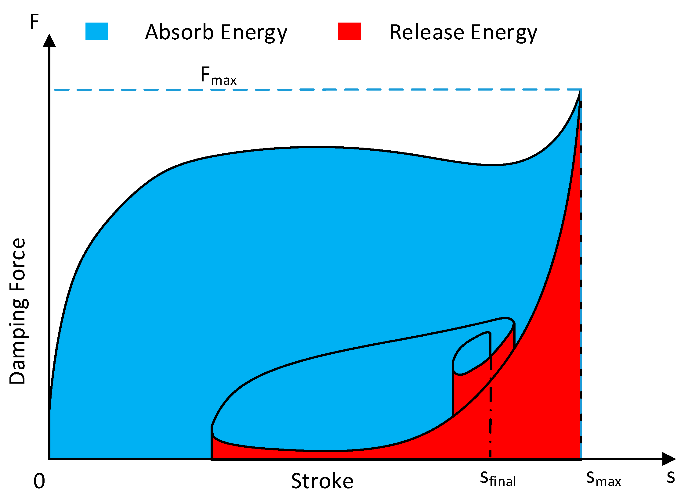
In this paper, an aircraft touch-down dynamic in landing is considered in order to assess landing gear performance. Accordingly, the process starts from the initial contact with the ground to the final equilibrium state. The key performance metric of the landing gear is the energy absorption ability of the damper through the entire period of impact absorption, which is called the total energy absorber efficiency η [19,21,22,23]. This value is described as the ratio between the total amount of energy absorbed and the product of the maximum force value Fmax and the maximum stroke reached smax, which is given by:
η = 0 s f i n a l F d d s s max F max
Figure 2 shows a shock absorber’s load–stroke curve of a typical landing gear system. The kinetic energy of an aircraft in landing is absorbed during only the compression stroke. From Equation (6), the tire force approximately equals to the damping force due to small un-sprung mass and thus the load–stroke curve roughly represents the behavior of the tire force during touch down. Due to aircraft safety, the tire must contact the ground, which means the tire force should always be positive. The passive damping coefficient C in Equation (3) is designed so that the tire force in the extension stroke is kept positive. However, if additional MR damping force is applied during the extension stroke, which generates negative damping (see Equation (4)), the tire force can be negative, and results in rebound of the tire and the landing gear from the ground. Therefore, it is highly desirable to make the MR controller active during only the compression stroke. Then, the semi-active condition in Equation (4) is turned into:
F M R = u   hardlim ( s ˙ ) hardlim   ( x ) = { 0        x 0 1        x > 0
The total energy absorber efficiency may change due to the variation of the energy absorption during touchdown in differing landing scenarios. The efficiency can be high in a certain landing scenario but low in another landing condition. Thus, the controller needs to be developed to maximize efficiency in differing landing conditions.
Aircraft mass m1 and sink speed v are the two main factors that significantly affect potential and kinematic energy during touchdown. In this paper, twelve combinations from the two factors are chosen to train and test the neural network, as shown in Table 2. The control target is to maximize the total energy absorber efficiency for every single landing case and also minimize the difference between them. Thus, the control target is the maximization of the cost function, which is given by:
J = E ( η ) + w Δ η
where
{ E ( η ) = 1 12 i = 1 12 η i Δ η = 1 12 i = 1 12 | η i E ( η ) |
and w = −1 is the scalar value.

4. Intelligent Controller Design

4.1. Neural Network Structure

Figure 3 depicts the architecture of the neural network used in this research. The neural network structure is a perceptron with three layers, which are an input layer, a hidden layer, and an output layer. The input layer has four inputs—stroke, aircraft acceleration, stroke velocity, and sink speed—where the former two come from the position sensor and accelerometer (Figure 1), and the latter two are derived from the sensor data. The hidden layer has n neurons, each of which constitutes an output vector (4 × 1). Thus, the hidden layer can be characterized by a weight matrix W1 (4 × 1) and a bias vector b1 (1 × n). The output layer only involves the electric current that will be applied to the MR damper. Thus, the output layer can be represented by a weight vector W2 (n × 1) and a scalar number b2. The relationship between the output and input is given by:
O u t p u t = f 2 ( f 1 ( W 1 × i n p u t + b 1 ) W 2 + b 2 )
where f1 and f2 are activation functions [13], which can be described by:
f 1 ( x ) = e x e x e x + e x f 2 ( x ) = { 0        if   x < 0 x        if   0 x 1 1        if   x > 1
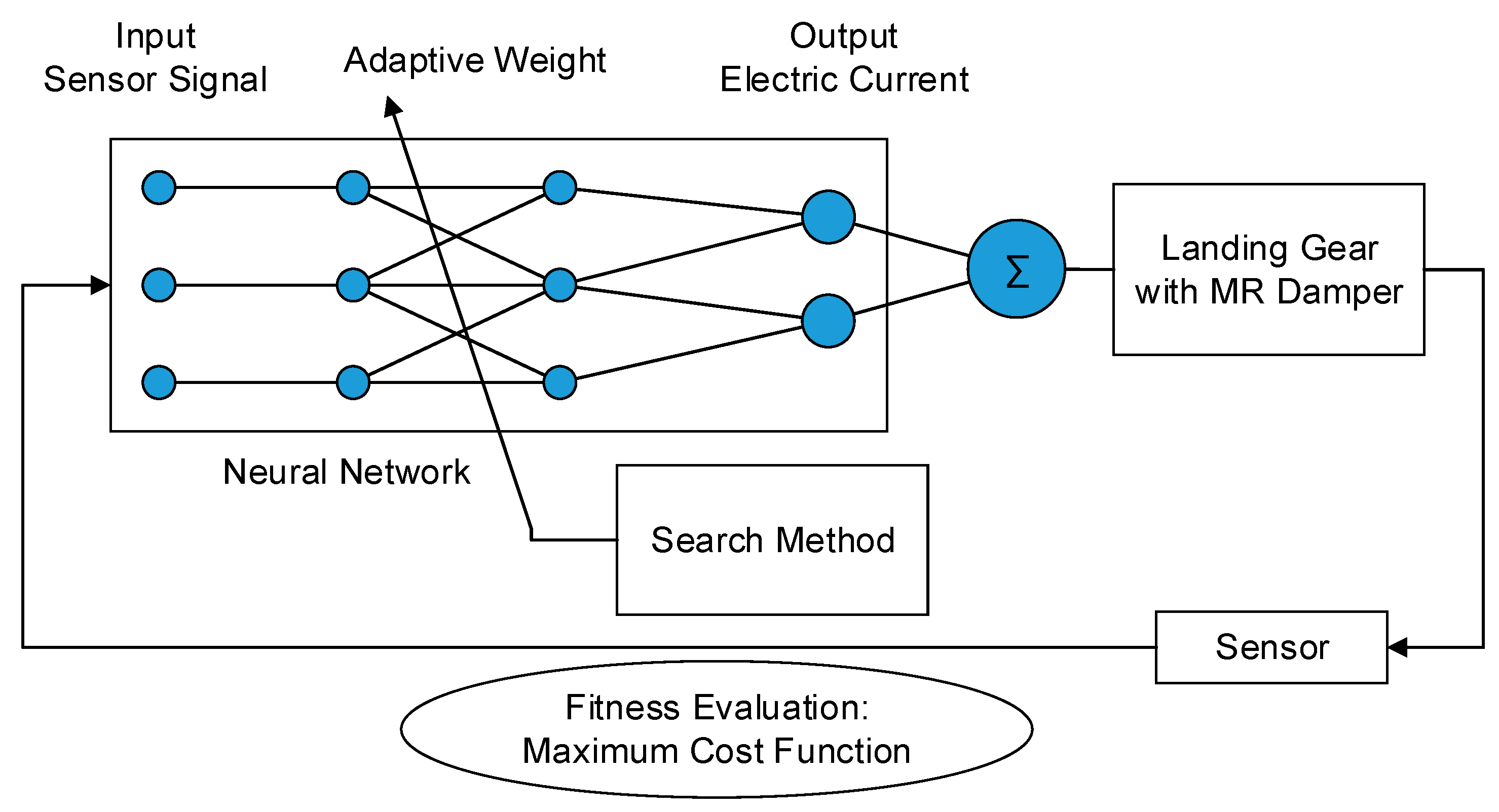
The training problem of the neural network is to determine the unknown parameters, which are W1, W2, b1, b2, and n, so that the cost function in Equation (11) is maximized. If an optimal electric current for this control target is known, supervised learning using the backpropagation algorithm [24] can be applied to solve this problem. However, the optimal electric current is also an unknown target. Thus, the training problem is solved by search methods using a genetic algorithm [13] or policy gradient estimation [25]. Figure 4 describes the learning process of landing gear equipped with an MR damper. It can be seen that the landing gear equipped with an MR damper in the touchdown phase is assumed to be an environment; the neural network controller is an agent that perceives its environment through sensors and acts upon that environment by applying the electric current on the MR damper. This agent uses a search method to choose the right actions to achieve the goal, i.e., maximizing the control target, and is accordingly called a goal-based agent [26].

4.2. Genetic Algorithm

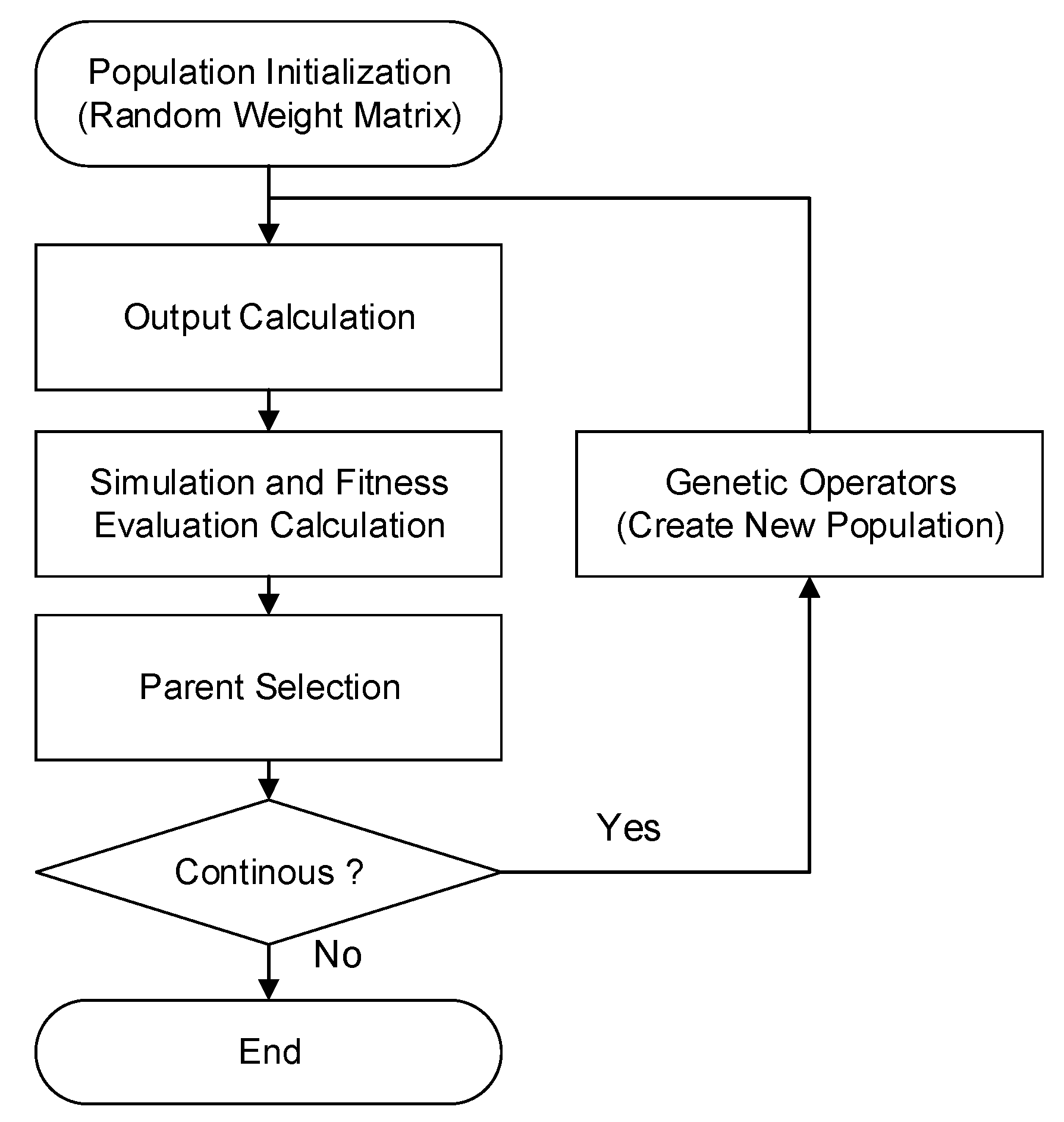
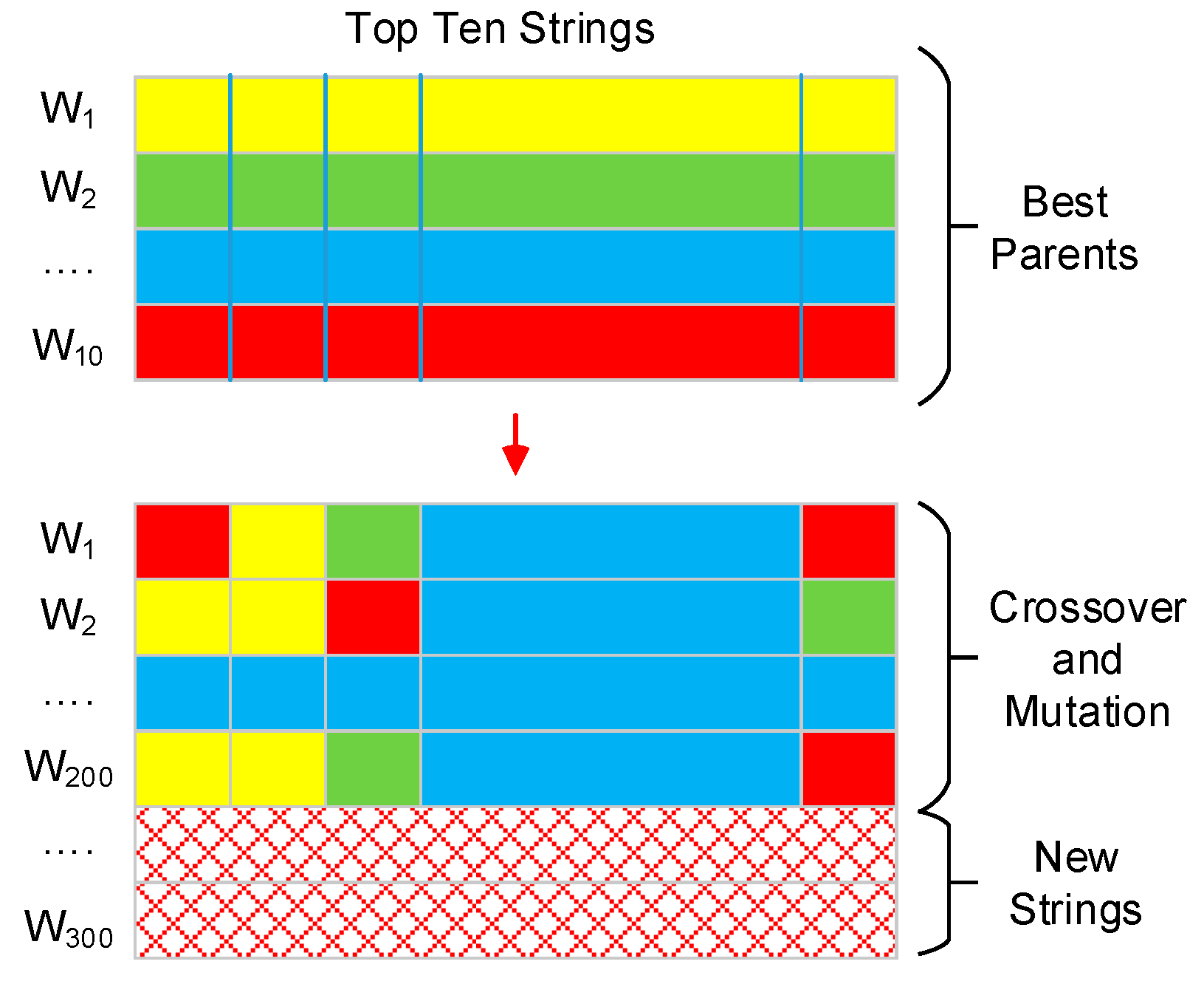
The genetic algorithm is an evolutionary computing algorithm inspired by the principle of evolution [13]. Figure 5 depicts the procedure in this paper that the genetic algorithm follows. From the beginning, all strings in the first generation are randomly generated in a sample space [−1, 1]p, where p is the number of the parameters, using a uniform distribution. The number of strings in the population must be large enough to ensure the algorithm convergence. Thus, this paper uses a population size of 300 strings after some preliminary studies. The main loop includes three steps. First, all strings in the population are subsequently simulated with the landing gear model. Next, the fitness of each string is calculated following Equation (11). The top ten strings, which claim the highest fitness values, are subsequently chosen as potential parents. Then, these parents are compared with the parents in the previous generation to choose the best 10 parents for creating the next generation. The next generation involves 100 new strings, which are also randomly generated using a uniform distribution, and 200 strings, which have evolved from the best parents, as can be seen in Figure 6. Both crossover and mutation are used in the evolution from the parent strings.

4.3. Policy Gradient Estimation

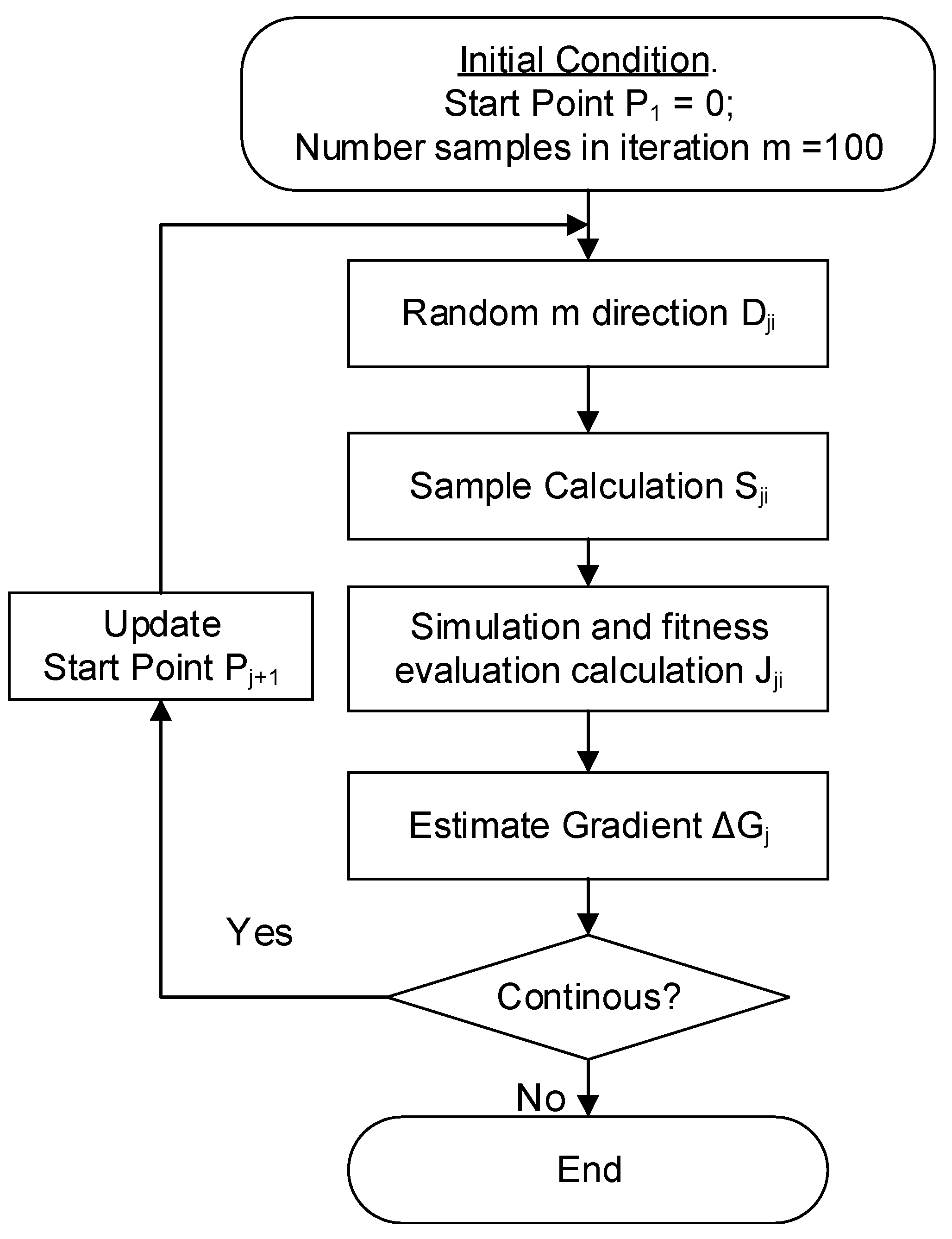
The policy gradient estimation (or stochastic gradient estimation) is a famous method in the framework of reinforcement learning [25]. Figure 7 depicts the policy gradient estimation algorithm.
From the beginning, the starting point P1 is a zero vector, indicating that all parameters in the neural network are zeros. In the jth iteration, m random directions Dji are generated in a small subspace [−0.4, 0.4]p. The number of directions m is chosen to be sufficiently large to approximate the fitness evaluation as a Gaussian distribution. Thus, this paper uses m = 100 after some preliminary studies. Additionally, the policy samples Sji are then calculated by:
Sji = sat(Pj + Dji)
Since the policy sample must be in the sample space [−1, 1]p, each element of the vector argument in the sat function is truncated. Each policy sample is then evaluated with the landing gear simulation. Next, the gradient ΔGj is defined as the average of the random directions [27], which is given by:
Δ G j = α i = 1 m J j i i = 1 m J j i D j i
where α is the learning rate, which decides the length of the gradient. If the learning rate is high, the algorithm is difficult to converge, and, if the learning rate is small, the algorithm converges with a high cost of calculation. Calculating the optimal learning rate is very difficult in an unknown system. For simplicity, the learning rate α = 2 is used after some preliminary studies. The algorithm will continue with the next starting point Pj+1:
Pj+1 = Pj + ΔGj

5. Results and Discussion

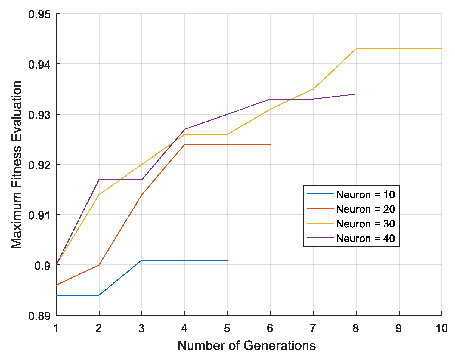
Figure 8 shows the simulation results of GA-NN with different neurons from 10 to 40 with step 10. As can be seen, the highest maximum fitness evaluation is approximately 0.94 with 30 neurons. Thus, the number of neurons is set to be 30 in the rest of this study. Figure 9 shows the simulation results of PGE-NN with the optimal number of neurons. It can be seen that PGE-NN also converts at 0.94. This indicates that the two methods produce similar results. Table 3 shows the execution time of GA-NN and PGE-NN. All simulations are executed by using MATLAB version 2016b. The computer has an Intel Core i7-7700 processor. It can be seen that the computation time of GA-NN takes approximately three times longer than that of PGE-NN to converge. Thus, the PGE-NN has an advantage in reducing the computation time.
Numerical simulations using different control methods are performed for verifying the effectiveness of the controller. A passive damper and an adaptive hybrid controller are tested for comparison to the proposed intelligent controller. The adaptive hybrid controller is taken from the previous work [19]. The adaptive hybrid controller is the combination of a skyhook controller and a force controller. In the skyhook controller, the skyhook gain is calculated separately in every single landing scenario. Additionally, the controller then autonomously adjusts the skyhook gain according to the estimated aircraft mass and sink speed by using a lookup table technique. In the force controller, the damping force is estimated based on the mathematical model and then maintained during the first compression stroke. Generally, the adaptive hybrid controller needs to determine the unknown parameters, which are aircraft mass, skyhook gain, and damping force, in different landing conditions. Because the system is assumed to be known exactly, the number of numerical simulations to determine the unknown parameters is less than 100. Thus, the execution time of the adaptive hybrid controller is dramatically smaller than the training time of the neural network. However, the most crucial factor in the efficiency of this method is the correctness of the landing gear model used in the controller.
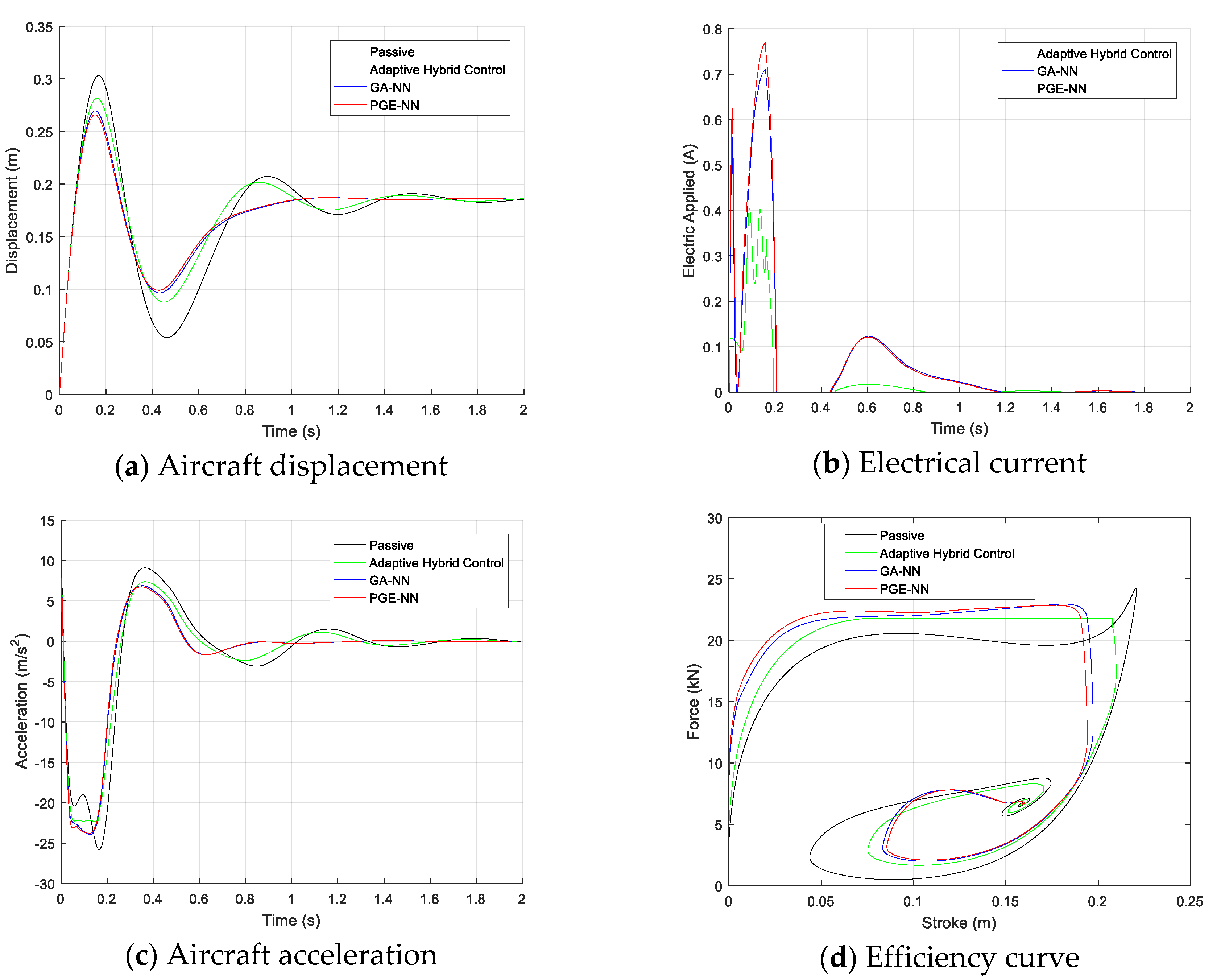
Table 4 and Figure 10 show the performance of the damper using different control methods for a heavy landing case. It can be seen that GA-NN and PGE-NN also maintain the damping force during the first compression stroke by their self-learning processes without requiring system knowledge. They produce slightly higher total energy absorber efficiencies than the adaptive hybrid controller. They also have smaller maximum stokes during landing, and they bring the system into an equilibrium state faster than the other controllers. However, they use a higher electric current than the adaptive hybrid controller. Thus, GA-NN and PGE-NN exhibit slightly greater acceleration in magnitude and also slightly higher damping force than that of the adaptive hybrid control. Generally, GA-NN and PGE-NN achieve marginally better performance than that of the adaptive hybrid controller.
Table 5 shows the landing gear’s performance using the passive damper and the adaptive hybrid control in fifteen landing cases, which are the twelve standard cases in Table 2 and three randomly generated ones. It can be seen that the adaptive hybrid control exhibits better performance than the passive damper. It produces higher total energy absorber efficiency, smaller maximum damping force, and also smaller maximum stroke. To achieve that result, there requires an accurate model of the landing gear system. This indicates that there is no significant difference between the estimated damping force and the real one. Additionally, the aircraft mass should also be estimated accurately before aircraft touchdown. Thus, the controller may not be useful if the model is unable to closely follow the real dynamics of an MR damper.
Table 6 describes the performance of the landing gear using GA-NN and PGE-NN in different landing conditions. It can be seen that GA-NN and PGE-NN exhibit similar levels of performance. In the twelve trained landing cases, the total energy absorber efficiency is very high, ranging from 94% to 97%. In particular, it should be noted that the proposed controller does not need the online estimation of landing conditions. In order to verify the generalization ability of the proposed controller, simulations in the three random landing cases are executed, which are out of data training. It can be seen that the proposed controller also exhibits comparable performance in the random cases. This indicates that the proposed controller is not overfitted.
Compared to the adaptive hybrid controller, the proposed controller produces a slightly higher maximum damping force; however, it achieves a marginally smaller maximum stroke. Thus, there is a small difference in total energy absorber efficiency between the proposed controller and the adaptive hybrid controller. Thus, the proposed controller exhibits similar adaptability to that of the adaptive hybrid controller in various landing conditions. Generally, the proposed controller exhibits comparable performance to the adaptive hybrid controller without any need for the online estimation of landing conditions and for explicit system knowledge.

6. Conclusions

This research has investigated intelligent techniques based on a neural network controller for aircraft landing gear equipped with a magnetorheological damper in differing landing scenarios. In this research, two algorithms, which are the genetic algorithm and policy gradient estimation, were applied to determine the optimal parameters in the neural network controller. The controller learned from a large number of trials. Thus, the main advantage of this method is that it runs autonomously without requiring system knowledge. Both the genetic algorithm and policy gradient estimation have produced similar results. Compared to the one of the best existing controllers, i.e., the adaptive hybrid controller, both the genetic algorithm-neural network and policy gradient estimation-neural network controllers delivered similar levels of performance to that of the adaptive hybrid control in different landing scenarios without requiring the landing condition estimation or the system knowledge. In future studies, the effectiveness of the proposed controller will be verified with experimental data from landing gear drop tests.

Author Contributions

Data curation, Q.V.L. and D.-S.J.; Formal analysis, Q.V.L. and D.-S.J.; Investigation, D.-S.J.; Methodology, D.-S.J. and J.-H.H.; Project administration, J.-H.H.; Software, Q.V.L.; Supervision, D.-S.J. and J.-H.H.; Writing—original draft, Q.V.L.; Writing—review & editing, D.-S.J. and J.-H.H. All authors have read and agreed to the published version of the manuscript.

Funding

This work was funded by the Ministry of Trade, Industry & Energy (MOTIE, Korea), grant number 10073291.

Acknowledgments

This work was supported by the Technology Innovation Program (intelligent landing gear with variable damping force for 1500lb class) (10073291).

Conflicts of Interest

The authors declare no conflict of interest.

References

  1. Choi, S.-B.; Han, Y.-M. Magnetorheological Fluid Technology Applications in Vehicle Systems; CRC Press Taylor & Francis Group: Boca Raton, FL, USA, 2013; ISBN 978-1-4398-5674-1. [Google Scholar]
  2. Choi, Y.-T.; Wereley, N.M. Vibration Control of a Landing Gear System Featuring Electrorheological/Magnetorheological Fluids. J. Aircr. 2003, 40, 432–439. [Google Scholar] [CrossRef]
  3. Batterbee, D.C.; Sims, N.D.; Stanway, R.; Wolejsza, Z. Magnetorheological landing gear: 1. A design methodology. Smart Mater. Struct. 2007, 16, 2429–2440. [Google Scholar] [CrossRef] [Green Version]
  4. Batterbee, D.C.; Sims, N.D.; Stanway, R.; Rennison, M. Magnetorheological landing gear: 2. Validation using experimental data. Smart Mater. Struct. 2007, 16, 2441–2452. [Google Scholar] [CrossRef]
  5. Fu, L.; Chen, S.; Bai, X.; Wang, J. Optimal control of aircraft landing gear state feedback based on magnetorheological damper. In Proceedings of the 2018 Chinese Control and Decision Conference (CCDC), Shenyang, China, 9–11 June 2018; pp. 6673–6676. [Google Scholar]
  6. Balamurugan, L.; Jancirani, J.; Eltantawie, M.A. Generalized magnetorheological (MR) damper model and its application in semi-active control of vehicle suspension system. Int. J. Automot. Technol. 2014, 15, 419–427. [Google Scholar] [CrossRef]
  7. Kang, B.-H.; Han, C.; Choi, S.-B. A sky-ground hook controller for efficiency enhancement of aircraft landing gear with MR damper. In Proceedings of the SPIE 10967, Active and Passive Smart Structures and Integrated Systems XIII, Denver, CO, USA, 3–7 March 2019; pp. 1–8. [Google Scholar] [CrossRef]
  8. Dong, X.M.; Xiong, G.W. Vibration Attenuation of Magnetorheological Landing Gear System with Human Simulated Intelligent Control. Math. Probl. Eng. 2013, 2013, 242476 . [Google Scholar] [CrossRef] [Green Version]
  9. Gharapurkar, A.A. Robust Semi-active Control of Aircraft Landing Gear System Equipped with Magnetorheological Dampers. Master’s Thesis, Concordia University, Montreal, QC, Canada, 2014. [Google Scholar]
  10. Li, F.; Wei, G.; Qi, W.; Xinhe, X. Modeling and adaptive control of magneto-rheological buffer system for aircraft landing gear. Appl. Math. Model. 2015, 39, 2509–2517. [Google Scholar] [CrossRef]
  11. Choi, Y.-T.; Robinson, R.; Hu, W.; Wereley, N.M.; Birchette, T.S.; Bolukbasi, A.O.; Woodhouse, J. Analysis and Control of a Magnetorheological Landing Gear System for a Helicopter. J. Am. Helicopter. Soc. 2016, 61, 1–8. [Google Scholar] [CrossRef]
  12. Yoon, J.-Y.; Kang, B.-H.; Kim, J.-H.; Choi, S.-B. New control logic based on mechanical energy conservation for aircraft landing gear system with magnetorheological dampers. Smart Mater. Struct. 2020, 29, 084003. [Google Scholar] [CrossRef]
  13. Konar, A. Computational Intelligence: Principles, Techniques and Applications; Springer: Berlin/Heidelberg, Germany, 2005; ISBN 3-540-20898-4. [Google Scholar]
  14. Tian, Y.; Pei, K.; Jana, S.; Ray, B. DeepTest: Automated testing of deep-neural-network-driven autonomous cars. In Proceedings of the 40th International Conference on Software Engineering—ICSE’18, Gothenburg, Sweden, 27 May–3 June 2018; pp. 303–314. [Google Scholar]
  15. Mosavi, A.; Varkonyi, A. Learning in Robotics. Int. J. Comput. Appl. 2017, 157, 8–11. [Google Scholar] [CrossRef]
  16. Parker, G.; Zbeda, R. Learning Area Coverage for a Self-Sufficient Hexapod Robot Using a Cyclic Genetic Algorithm. IEEE Syst. J. 2014, 8, 778–790. [Google Scholar] [CrossRef]
  17. Zhu, S.X.; Han, Y.; Wang, B. Application of BP Neural Network PID Controller in Landing Gear Based on MRF Damper. Appl. Mech. Mater. 2015, 779, 226–232. [Google Scholar] [CrossRef]
  18. Holmes, G.; Sartor, P.; Reed, S.; Southern, P.; Worden, K.; Cross, E. Prediction of landing gear loads using machine learning techniques. Struct. Health Monit. 2016, 15, 568–582. [Google Scholar] [CrossRef]
  19. Luong, Q.V.; Jang, D.-S.; Hwang, J.-H. Robust Adaptive Control for an Aircraft Landing Gear Equipped with a Magnetorheological Damper. Appl. Sci. 2020, 10, 1459. [Google Scholar] [CrossRef] [Green Version]
  20. Han, C.; Kang, B.-H.; Choi, S.-B.; Tak, J.M.; Hwang, J.-H. Control of Landing Efficiency of an Aircraft Landing Gear System with Magnetorheological Dampers. J. Aircr. 2019, 56, 1980–1986. [Google Scholar] [CrossRef]
  21. Han, C.; Kim, B.-G.; Choi, S.-B. Design of a New Magnetorheological Damper Based on Passive Oleo-Pneumatic Landing Gear. J. Aircr. 2018, 55, 2510–2520. [Google Scholar] [CrossRef]
  22. Norman, S.C. Aircraft Landing Gear Design: Principles and Practices; AIAA Education; American Institute of Aeronautics and Astronautics: Reston, VA, USA, 1988; ISBN 0-930403-41-X. [Google Scholar]
  23. Li, Y.; Jiang, J.Z.; Neild, S.A.; Wang, H. Optimal Inerter-Based Shock–Strut Configurations for Landing-Gear Touchdown Performance. J. Aircr. 2017, 54, 1901–1909. [Google Scholar] [CrossRef] [Green Version]
  24. Hagan, M.T.; Demuth, H.B.; Beale, M.H.; De Jesús, O. Neural Network Design, 2nd ed.; Martin Hagan: Stillwater, OK, USA, 2014; ISBN 0-9717321-1-6. [Google Scholar]
  25. Sutton, R.S.; Barto, A.G. Reinforcement Learning: An Introduction, 2nd ed.; A Bradford Book; The MIT Press: Cambridge, MA, USA; London, UK, 2018; ISBN 978-0-262-03924-6. [Google Scholar]
  26. Russell, S.; Norvig, P. Artificial Intelligence A Modern Approach, 3rd ed.; Pearson Education Limited: Essex, UK, 2016; ISBN 1-292-15396-2. [Google Scholar]
  27. Fazel, M.; Ge, R.; Kakade, S.M.; Mesbahi, M. Global Convergence of Policy Gradient Methods for the Linear Quadratic Regulator. In Proceedings of the 35th International Conference on Machine Learning, Stockholm, Sweden, 10–15 July 2018; p. 10. [Google Scholar]
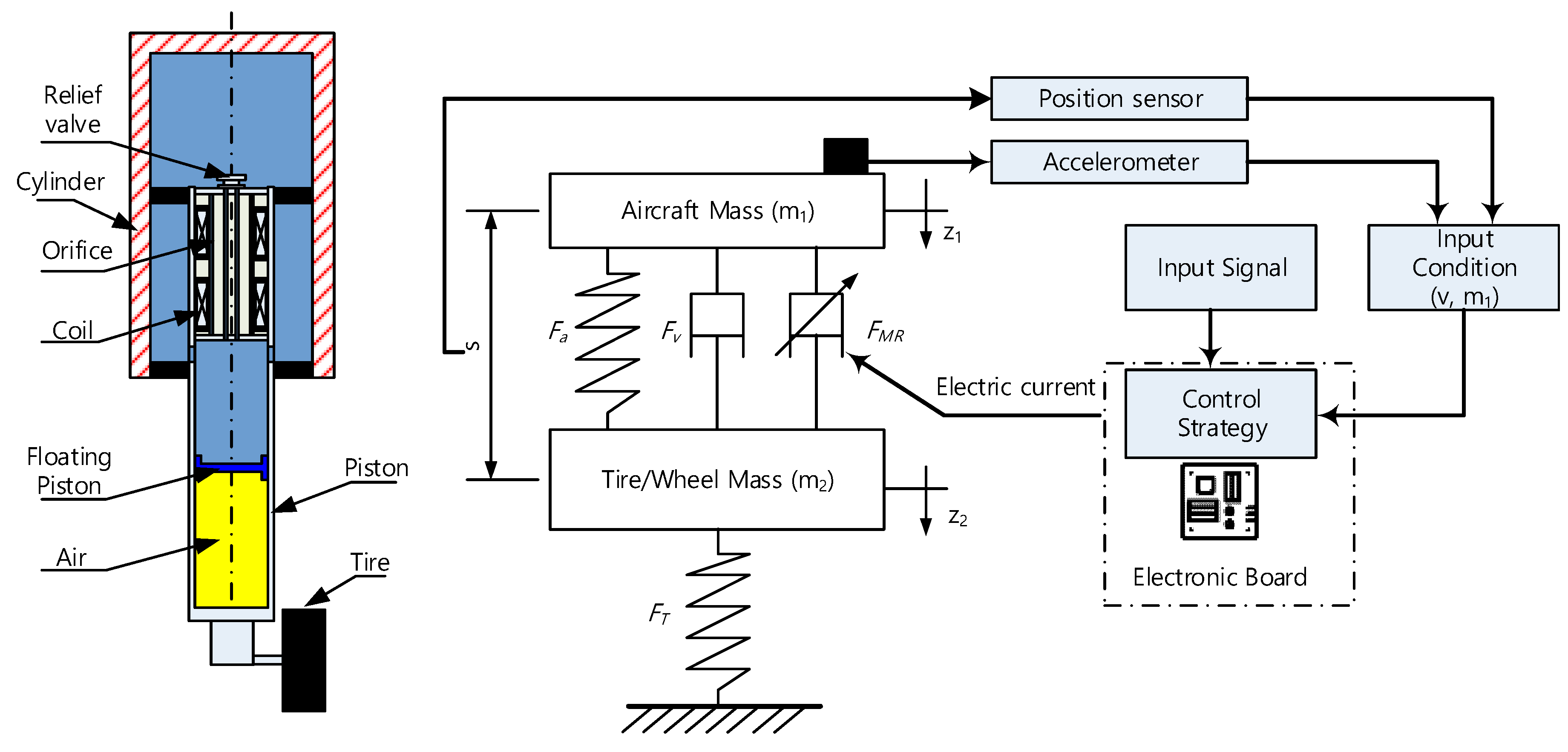
Figure 1. Landing gear system concept.
Applsci 10 05962 g001
Figure 2. Load–stroke curve.
Applsci 10 05962 g002
Figure 3. Neural network structure.
Applsci 10 05962 g003
Figure 4. Landing gear learning process.
Applsci 10 05962 g004
Figure 5. Genetic algorithm.
Applsci 10 05962 g005
Figure 6. Generating a new population.
Applsci 10 05962 g006
Figure 7. Policy gradient estimation.
Applsci 10 05962 g007
Figure 8. Simulation results of GA-NN with different neurons.
Applsci 10 05962 g008
Figure 9. Simulation results of PGE-NN with 30 neurons.
Applsci 10 05962 g009
Figure 10. Comparative simulation results of the passive damper, adaptive hybrid controller, GA-NN, and PGE-NN control at m1 = 680 kg, v = 3 m/s.
Applsci 10 05962 g010
Table 1. Landing gear parameters.
SymbolQuantityValueUnit
Apcross-area of head piston2.5 × 10−3m2
btire force index1.13
Cviscous damping coefficient6.58kNs/m
ggravitational acceleration9.81m/s2
m1sprung mass (aircraft mass)560–680kg
m2un-sprung mass18kg
npolytropic process index1.3
p0initial air chamber charging pressure810kPa
pATMatmospheric pressure101.3kPa
kTtire force constant412kN/m
vinitial sink speed of aircraft at touchdown2–3m/s
V0initial air chamber volume6.37 × 10−4m3
ucontrol input (electrical current)0–1A
Table 2. Efficiency symbols in the differing landing scenarios.
Aircraft Mass(kg)
560600640680
Sink speed
(m/s)
2η1η2η3η4
2.5η5η6η7η8
3η9η10η11η12
Table 3. Comparison of the execution time between GA-NN and PGE-NN with 30 neurons.
ParameterTotal Loops for ConvergenceNumber Simulation per LoopExecution Time per Simulations
(second)
Total Execution Time
(hour)
GA-NN1030013.611.3
PGE-NN1110012.93.9
Table 4. Efficiency of the landing gear using the passive damper, adaptive hybrid control, GA-NN, and PGE-NN in the case of m1 = 680 kg and v = 3 m/s.
Maximum of Stroke smax (m)Maximum of Damping Force Fmax (kN)Total Energy Absorber Efficiency η (%)
Passive Damper0.22124.280.4
Adaptive Hybrid Control0.21021.894.0
GA-NN0.19722.994.6
PGE-NN0.19422.894.9
Table 5. Damper performance using the passive damping and adaptive hybrid control in differing landing cases.
Passive DamperAdaptive Hybrid Control
Fmax (kN)smax (m)η (%)Fmax (kN)smax (m)η (%)
m1 = 560 kg
v = 2 m/s14.30.17779.414.30.14696.5
v = 2.5 m/s16.90.19381.116.90.16495.8
v = 3 m/s19.70.20784.919.70.18694.6
m1 = 600 kg
v = 2 m/s14.50.18680.915.30.14695.3
v = 2.5 m/s17.20.20083.318.20.16098.8
v = 3 m/s20.00.21287.921.20.18197.4
m1 = 640 kg
v = 2 m/s14.70.19482.715.60.15796.4
v = 2.5 m/s17.50.20785.918.50.17496.4
v = 3 m/s21.50.21786.121.50.19595.8
m1 = 680 kg
v = 2 m/s14.90.20184.915.80.16895.9
v = 2.5 m/s18.60.21284.718.80.18994.1
v = 3 m/s24.20.22180.421.80.21094.0
m1 = 575 kg (Random Case 1)
v = 2.25 m/s15.70.18880.615.70.15896.0
m2 = 625 kg (Random Case 2)
v = 2.75 m/s18.90.21087.319.90.17896.9
m3 = 654 kg (Random Case 3)
v = 2.35 m/s16.80.20585.717.70.17396.0
Table 6. Damper performance of the damper using GA-NN and PGE-NN in differing landing cases.
GA-NNPGE-NN
Fmax (kN)smax (m)η (%)Fmax (kN)smax (m)η (%)
m1 = 560 kg
v = 2 m/s14.80.14494.414.70.14494.7
v = 2.5 m/s17.70.15795.617.60.15795.5
v = 3 m/s20.60.17794.020.60.17794.8
m1 = 600 kg
v = 2 m/s15.50.15094.415.30.15095.4
v = 2.5 m/s18.10.16496.818.10.16497.3
v = 3 m/s21.10.18495.521.00.18396.9
m1 = 640 kg
v = 2 m/s16.20.15594.216.10.15594.8
v = 2.5 m/s18.90.17195.818.80.16997.3
v = 3 m/s21.70.19196.121.70.18997.6
m1 = 680 kg
v = 2 m/s16.90.16094.616.80.16095.0
v = 2.5 m/s19.70.17894.919.60.17595.0
v = 3 m/s22.90.19794.622.80.19494.9
m1 = 575 kg (Random Case 1)
v = 2.25 m/s16.40.14997.816.10.15297.2
m2 = 625 kg (Random Case 2)
v = 2.75 m/s20.00.17996.119.60.18296.3
m3 = 654 kg (Random Case 3)
v = 2.35 m/s18.40.16795.818.20.18295.8