1. Introduction
The ElectroMagnetic Launch (EML) technology uses electric propulsion to accelerate objects at high speeds. Because of its superior performance it is substituting several launch systems. Coil and rail launchers are the most used alternative solutions [
1,
2].
Induction launchers are substantially linear tubular motors, usually air cored. They consist of a barrel formed by an array of (stator) coils and a conductive cylinder moving inside them. Induction launchers are operated as travelling wave induction launchers or as pulsed induction launchers. In the first operation mode, the stator coils are grouped in sections that are energized in a polyphase fashion in order to create a traveling wave of flux density in the region occupied by the sleeve. In the second one the stator coils are fed in sequence by a set of capacitor driven circuit [
3,
4,
5,
6,
7].
The Electro-Magnetic Aircraft Launch System (EMALS) is another important example of application of the electromagnetic launch technology. It has been introduced in substitution of the steam catapults for the take-off of airplanes from the new class of carriers of the US Navy [
8,
9,
10,
11]. With respect to the steam catapult EMALS is able to produce a smooth and controllable acceleration profile with a consequent reduction of the stress on the aircrafts. Moreover it is able to accelerate heavier aircrafts with reduced weight, cost and maintenance requirements. EMALS has been recently proposed for civil aircrafts [
12]. Ambitious programs for space application of electromagnetic launchers are under investigation [
13,
14].
A rail launcher is constituted by two conductive rails with a conductive armature (slab or c-shaped) free to slide inside them. At the beginning of the launch the armature is located near the breech of the launcher where a feeding generator is connected between the rails. The current flowing in the rails (and in the armature) produces a flux density distribution in correspondence of the armature, where the interaction with its current produces a thrust force that accelerates the armature. The main drawbacks affecting the rail launchers are a consequence of the Velocity Skin Effect (VSE) which is caused by the limited diffusion rate of the current in the rails as the armature moves; VES produces a concentration of the current in the rear portion of the armature near the rails [
15,
16,
17,
18]. The importance of VSE increases with the speed and it is one of the causes which may prevent the use of rail launchers at very high speed. The availability of numerical tools for the investigation of VSE and for the design of countermeasures to limit its effects on the launcher performance are of paramount importance [
17,
19,
20].
When considering a solid armature rail launcher, the choice of an air-core compensated pulsed alternator (compulsator) as the feeding device seems to be one of the most promising technology [
21]. The absence of ferromagnetic materials allows achieving a very low value of internal inductances. The addition of compensating windings or conductive shields further reduce the internal inductance, so increasing the peak value of the output pulsed current. Moreover, by proper positioning of compensating components, it is possible to shape the current pulse to improve the performance of the launchers, both in terms of muzzle speed and efficiency. As reported in the scientific literature, the maximum speed of an air-core rotor can reach higher values than those in an iron-core one, increasing the stored energy [
22,
23].
Many papers, based on analytical or numerical models, have been published in the past years to investigate the performance of the air-core compulsator [
24,
25,
26]. However, the majority of these studies are focused on the performance of the compulsator as a stand-alone device and adopt a simple time varying equivalent circuit to model the rail launcher. Similarly happens for rail launchers, where often the waveforms produced by the feeding devices are assigned, especially when the rotating machines are considered.
Accurate model identification and parameters extraction of the lumped equivalent circuit for these devices may be difficult to achieve since both rail launchers and compulsators are inherently time-varying and nonlinear electromechanical devices and consequently the parameters that identify the equivalent circuit of one device may depend on the operating conditions of the whole system and on the characteristics of the other device. A strong-coupled 3D electromechanical analysis of the interacting devices seems to be the only option able to provide accurate results. This paper discusses the coupled electromechanical analysis of the whole launch package by using the research code EN4EM previously developed by the authors.
In order to avoid confusion, in the remaining of the paper the phrase “strong coupling” will be reserved to the magnetoquasistatic-mechanical problems, arising when analyzing a device with conductors in relative motion. “Strong coupling” is necessary when analyzing high speed devices and it is inherently provided by underlying formulation of EN4EM. The phrase “strong-interaction” is reserved to indicate a simultaneous full 3D “strong coupled” analysis of the rail launcher and its feeding compulsator. Moreover, the phrase “weak-interaction” is reserved for those analyses where one of the devices is substituted with a lumped equivalent circuit and the other is analyzed by a 3D “strong coupled” model. The “equivalent circuit” is reserved for zero-dimensional voltage-current dependencies at the terminals of a device. A lumped “equivalent circuit” is usually unable to provide information about the spatial distribution of the electromechanical quantities inside the device. Finally, the phase “equivalent network” is related to EN4EM and, as it will be shown in the next section, is used to indicate the internal procedure of the code which builds an electric network whose currents are uniquely related to the current density distribution in a device.
To best of the authors’ knowledge, scientific literature does not report any “strong interaction” analysis between rail launcher and compulsator capable to consider two mechanical degrees of freedom (one rotation for the compulsator and one translation for the launcher) together with high speed sliding contacts. Considering that the components and the materials used in EML technology are heavily stressed from the electrical, mechanical and thermal point of view, a tools which allows an accurate coupled analysis represents a valuable resource.
The manuscript is organized as follows.
Section 2 briefly summarizes the adopted numerical formulation.
Section 3 shows two examples of the “weak interaction” analysis and further justifies the motivations of the research by discussing the results of these analyses. In
Section 5, the “strong interaction” analysis of the whole system is carried on and its results are compare with those by a “weak interaction” analysis. Finally, some concluding remarks are reported.
2. Numerical Formulation
The 3D numerical analysis of multi degrees of freedom electromechanical devices represents a challenging, still open problem, which poses several critical issues. Several commercial codes, typically based on the Finite Elements Method (FEM), provide packages for coupled electro-mechanical analysis, but they seem to be not very effective with multiple degrees of freedom and with sliding contacts. Moving conductors and sliding contacts usually require remeshing of the domains with consequent increase of computational times and potential numerical instabilities.
Integral Formulations (e.g., the Method of Moments) seem to work quite well with moving domains since they require the discretization of the active regions only (namely conductors and ferromagnetic materials), so avoiding the problem of coupling meshes with different speeds. Integral formulations implicitly enforce the far field boundary conditions, and are able to produce accurate results by using coarse discretization (when compared with those required by FEM).
The numerical investigation of the complete launch system has been performed by the research code EN4EM. It is based on an integral formulation, and it is under continuous development by the authors for investigating electromechanical systems [
27,
28,
29,
30,
31,
32,
33,
34].
EN4EM applied to the launch package is able to simulate the whole system considering the characteristics of the two devices and taking into account their “strong interaction”.
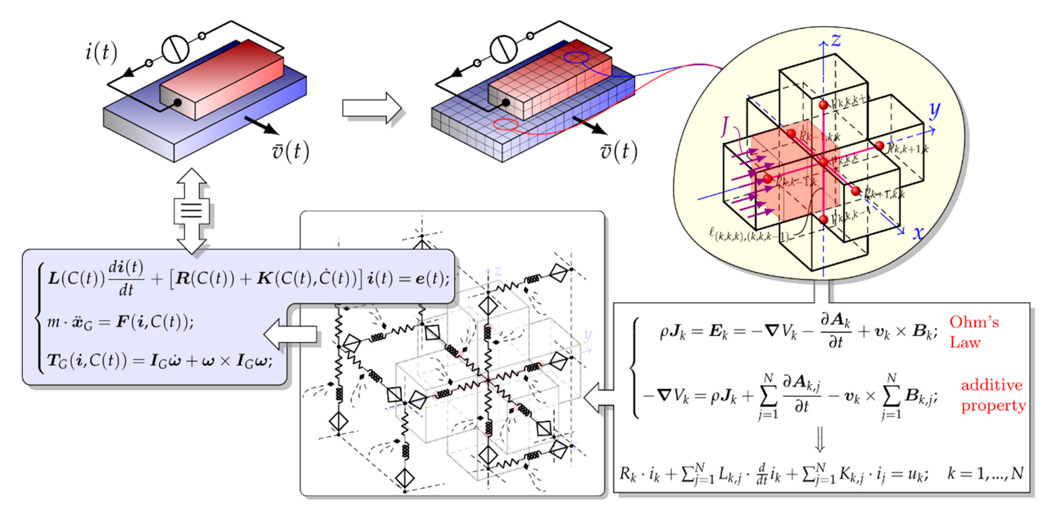
Figure 1 shows the steps of a conceptual flow chart of the numerical formulation: discretization in elementary volumes, writing and integration of Ohm’s law, arrangement in an electric network and writing of the governing electro-mechanical equations. The usual notations for the electromagnetic quantities in
Figure 1 are adopted according to the
Table 1.
With reference to the inset in the bottom right of
Figure 1, Ohm’s law is written in the conductive elementary volumes where a uniform current distribution is assumed (row #1 of the inset). The additive properties of the integrals with respect to the integration domain allows expressing the fields and potentials in the
k-th conductive elementary volume as a summation of contribution due to the currents in the other volumes (row #2 of the inset). Finally integration on the
k-th elementary volume leads to an equation that can be seen as the voltage-current relationship of a branch that is a series connection of a resistor, an inductor coupled with other inductors, and a voltage generator controlled by the currents in other elementary volumes (row #3). The equivalent network of the device is built by connecting the terminals of the branches so obtained. In case of a multi-device system, the code is able to model separately the different devices by their equivalent networks. Then, all these networks are connected together according to the relative positions of the corresponding elementary volumes and to the presence of electrical contacts between them. The described procedure has been applied to model the launcher and the compulsator, obtaining a whole model composed of thousands of branches.
Mesh analysis yields to the governing equations written in matrix form:
The values of the elements of the matrices in (1) are function of the system configuration
and its derivative
(i.e., the relative positions and velocities of the elementary volumes used to discretize the devices respectively). Coupling between electrical and mechanical equations is achieved by the terms
that, once integrated on the elementary volumes, are assembled to form the matrix of the motional terms
, and by the terms
which are integrated to provide the forces and the torques on the moving parts of the device. The mechanical equation for the armature of the launcher is:
while the equation for the compulsator are:
In the above equations
represents the resultant force on the launcher armature and
m is its mass,
is the resultant torque on the rotor of the compulsator and
is its inertia tensor. The coupled differential equations for electrical and mechanical equilibrium are time varying, and the resulting system is nonlinear; integration is carried out as described in [
27,
28].
It is worth to mention that the currents in the branches of the equivalent network are not fictitious currents. The current in a branch of the equivalent network is in correspondence with one component of the current density of an elementary volumes as shown by the insets in the upper right and in the lower left corners in
Figure 1. By the above described equivalent network the distribution of all the relevant electromechanical quantities can be evaluated everywhere in the whole system. In particular, the expression of the force by the term
allows to evaluate its distribution in each elementary volumes and to determine the contribution to the total dynamical action in materials that are usually heavily stressed when used in EML technology.
Simultaneous analysis of interacting devices simply requires building a bigger equivalent network constituted by the properly connected equivalent networks of the components. This implements a “strong interaction” between devices for which a “strong coupled” analysis is performed.
If the devices can be assumed magnetically uncoupled (i.e., leakage magnetic fluxes from a device that links the others are negligible) independent networks are built, linked together at the common terminals and simultaneously solved. It is worth to remark that the topology of the resultant network is the same than that of the more general case of magnetically coupled devices. The only difference lies in the filling of the inductance matrix and of the motional terms matrix , which are more densely populated in the latter case.
Coupling of the equivalent network so far described with external circuits is straightforward and this will be performed in the next section to investigate the “weak interaction” between the rail launcher and the compulsator.
The presence of sliding contacts has been taken into account by introducing an auxiliary network [
20]. Considering that the motion in the rail launcher is characterized by a straight trajectory, all the possible contacts between elementary volumes on the rails and on the armature are known a priori. A new branch is set for each couple of volumes (one on the inner parts of the rails and the other on the faced outer surfaces of the armature) that can have a contact during the motion.
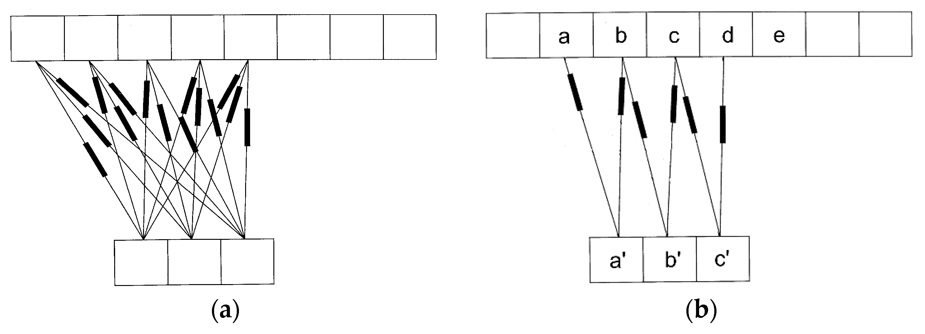
Figure 2 shows an example of a set of auxiliary branches that take into account the sliding contacts. The circuit elements in the auxiliary branches are function of the shared portion of the faces (if any) between the two volumes. When the shared portion is zero, the auxiliary branch opens. The proposed model of the sliding contacts is coherent with the adopted formulation based on an equivalent network of the entire system.
Finally the introduction of the equivalent network allows the use of advanced analysis techniques for the evaluation of the sensitivity of the response with respect to parameter variation [
35]. This represents an important tool in gradient based optimization processes.
EN4EM was validated by comparison with results produced by other numerical codes and with experimental data [
5,
6,
27,
28,
31,
32].
3. Weak Interaction Analysis
In this section the analysis based on the “weak interaction” between rail launcher and compulsator will be critically reviewed and the difficulties of the equivalent circuit extraction will be discussed.
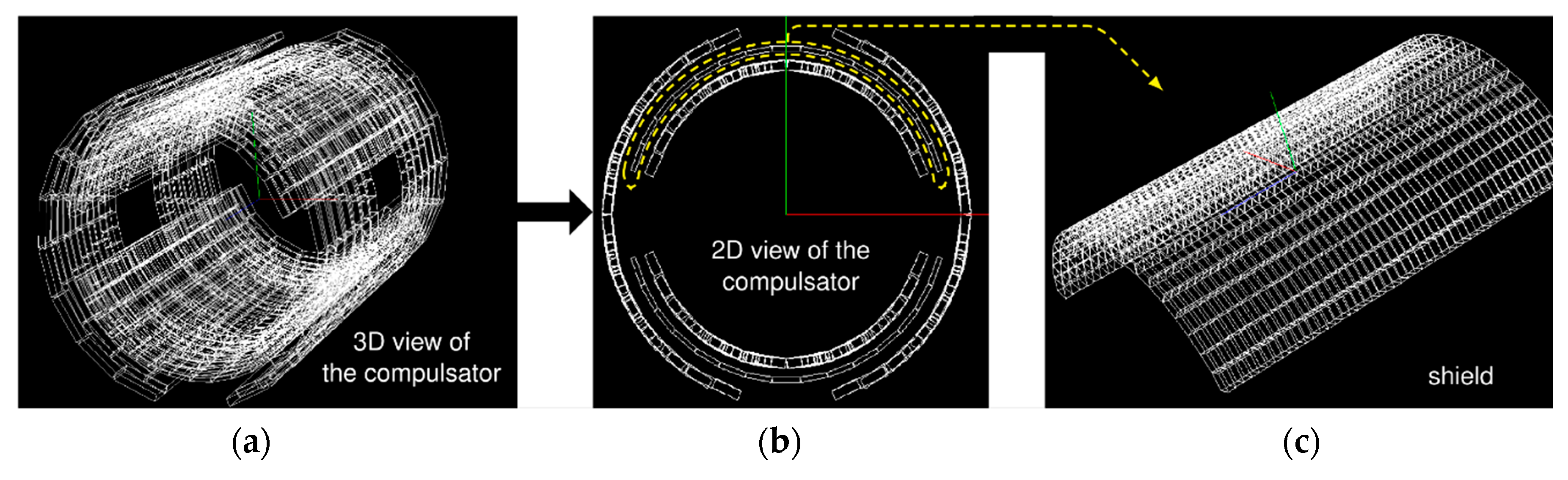
Figure 3 shows the active parts of a single-phase, two-pole compulsator with selective passive compensation provided by a discontinuous conductive shield. The inner part of the device consists of two stationary field coils which produce a magnetic flux density distribution whose axis is in the vertical direction (
Figure 3b). The two series connected armature windings are located on the rotor which is the outer part of the machine.
Figure 3c shows the stationary compensating shields that are in the central part of the machine.
Figure 3a shows a 3D view of the device. A more detailed description is reported in [
29].
When using a compulsator to feed a rail launcher, its rotor has to be preliminarily driven to a proper angular speed at no load conditions; part of the stored kinetic energy of the rotor will be delivered to the railgun armature. At the firing instant, the armature windings of the compulsator are connected to the rails of the launcher. During the launch, the rail armature accelerates and at the same time, the rotating part of the compulsator decreases its angular speed. The rates of change of the speeds of both the moving parts (and consequently their positions) are not known a-priori and substantially depend on the delivered current.
Since the simultaneous 3D analysis of the two electromechanical devices can be very time consuming, a common practice is to substitute one or both the device with equivalent circuits. This procedure may lead to significant error in the current flowing in the devices because of the difficulties in the determination of the topology and of the parameter extraction of the equivalent circuit.
Referring to the compulsator, when looking for a lumped equivalent circuit, we have to distinguish between the two compensation techniques usually adopted. When compensation is achieved by the use of shorted discrete coils, we can consider the self and mutual inductances of all windings (field, armature and compensating ones). Considering that the values of the mutual inductances depend on relative angular positions only, the lumped equivalent circuit of the compulsator is able to give accurate results; its building is a matter of evaluation (experimental or by computations) of self and mutual coefficients and EN4EM can be used as an extraction tool.
Things go in a different way when non-uniform (discontinuous) compensating shields are used. In these devices, the extraction of the values of the equivalent internal inductance L is not as straightforward as with shorted discrete coils, since it is function of the position of the rotor, as well as of the speed of the rotor, which is not known and varies during the system operation.
In fact, the speed of the rotor imposes the frequency of the electrical quantities in the shield, which in turn determines the path and the amplitude of the induced currents and their shielding effects which contribute to the internal equivalent inductance.
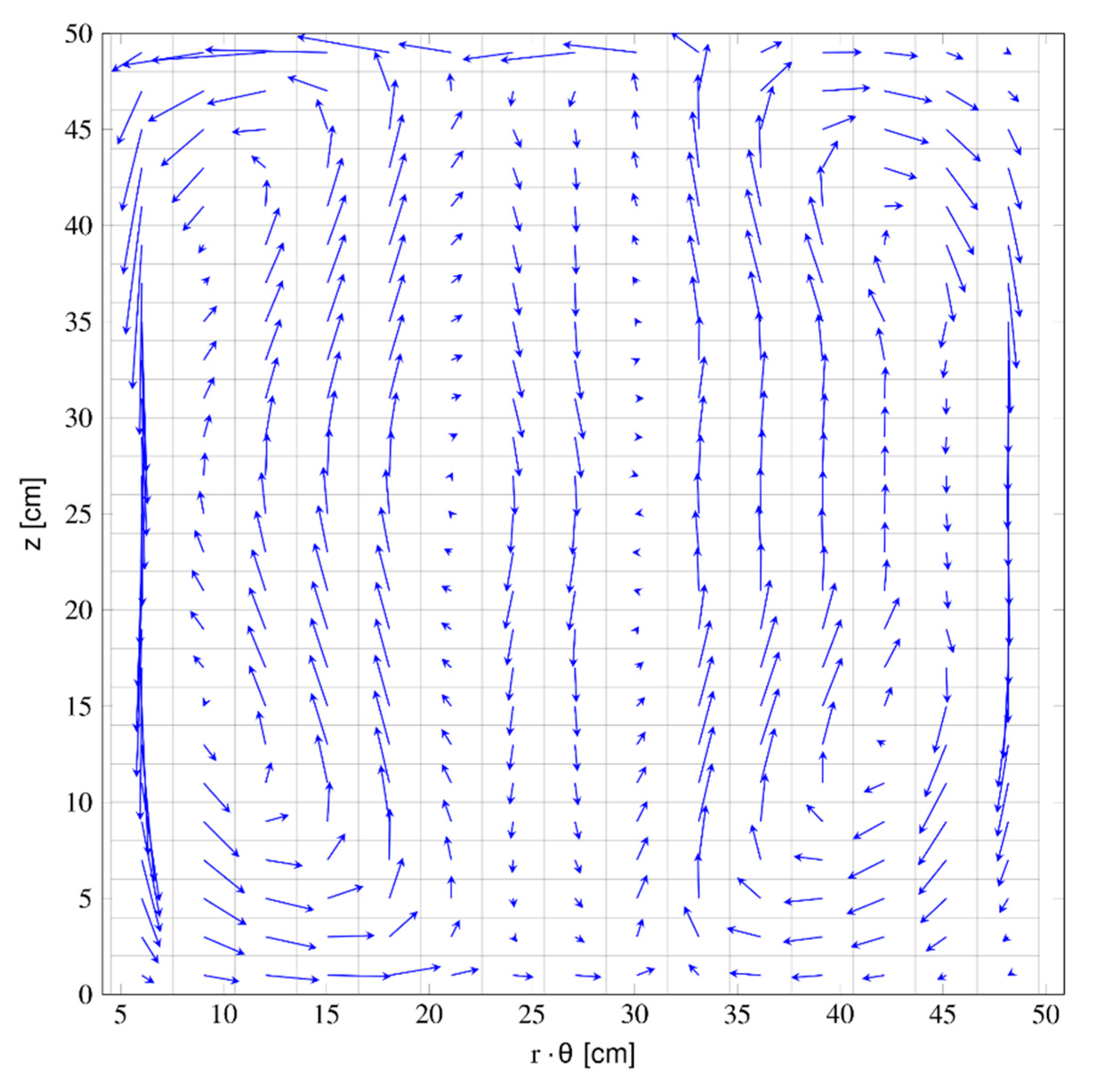
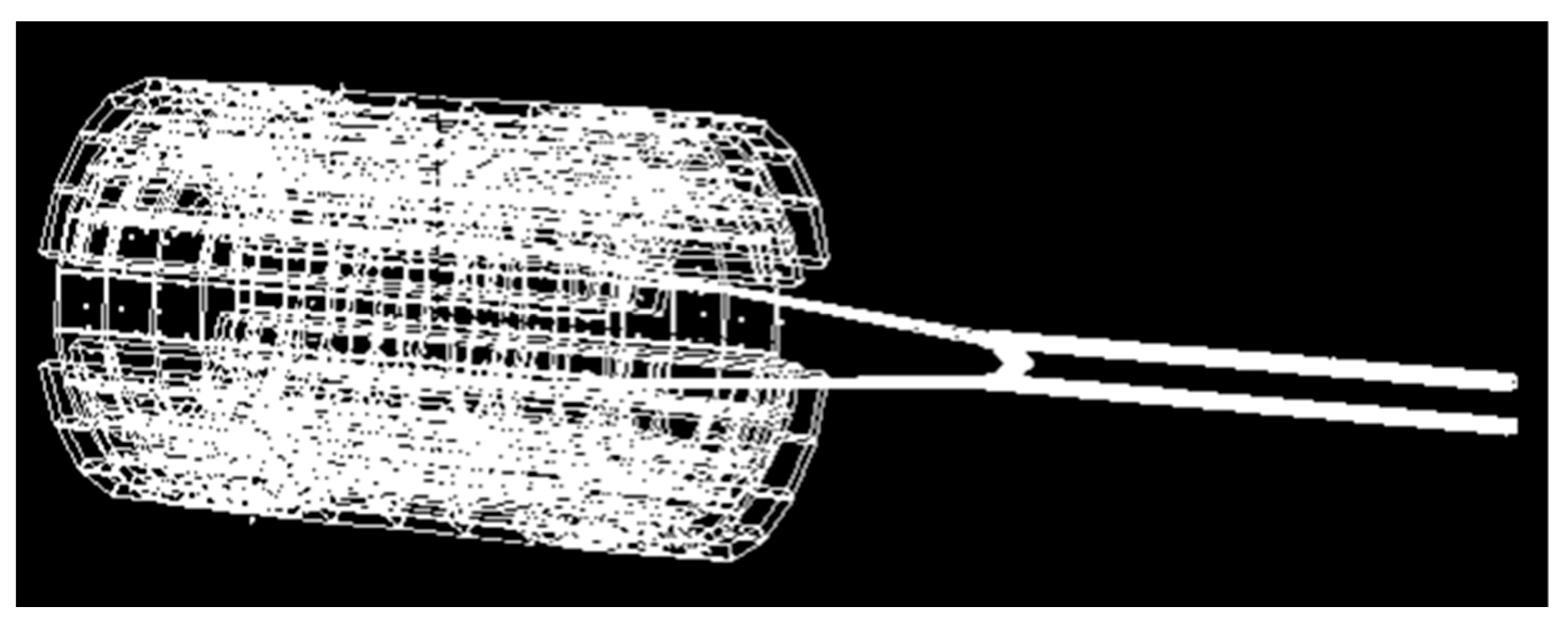
Figure 4 shows an example of eddy currents distribution on one of the discontinuous compensating shields of the compulsator above described whose operating conditions are reported in [
29]. In particular the compulsator was loaded with a simple lumped R-L equivalent circuit representing the rail launcher. The rectangle in
Figure 4 represents the flattened cylindrical surface shown
Figure 3c.
The equivalent internal inductance of the compulsator, as well as the electromotive force at the terminals of the machine, are functions of the distribution of the currents on the shields. Expressing these functional dependencies represents a challenging problem.
Similar difficulties arise when looking for an equivalent circuit of the rail launcher.
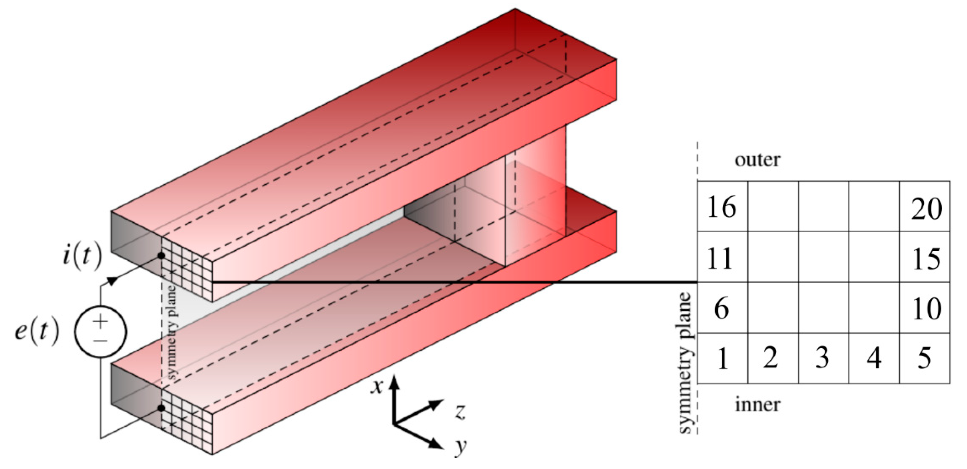
Figure 5 shows a rail launcher fed by an ideal voltage source whose waveform is given by
. Details about the geometry are in
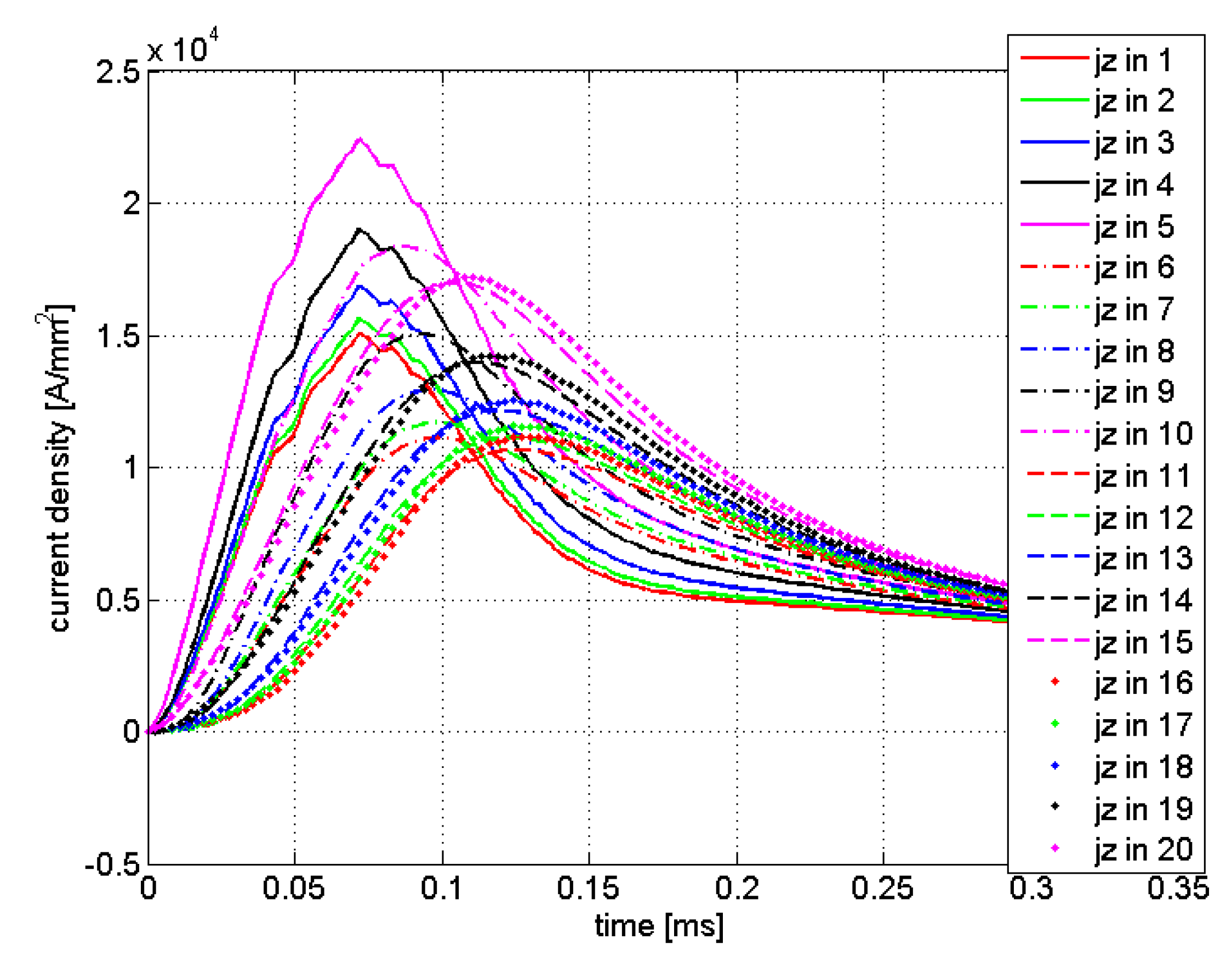
Table 2. In this figure, 20 elementary volumes located near the launcher breech are shown. The device was analyzed by EN4EM and the current density waveforms in the evidenced volumes are reported in
Figure 6. The solid curves are associated with the labelled sections in reported in the inset of
Figure 5; the greatest current density occurs in the section #5 in the inner part of the rail. The peak values became smaller as the outer boundary of the rail is approached. The reported waveforms put into evidence the uneven current density distribution in the rail section for most of the launch time, the ratio between the maximum and the minimum value is greater than two. This behavior is a consequence of the skin and proximity effects; also, the velocity skin effect has an heavy impact on the current distribution, which is a function of the rate of change of the electrical quantities imposed by the generator and the rate of change of the mechanical quantities i.e., the speed of the armature [
36,
37]. Both these quantities change during the launch.
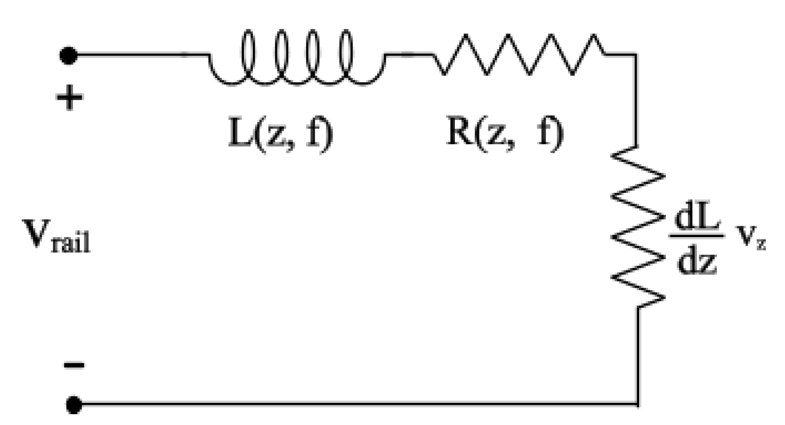
The basic equivalent circuit of the railgun, here shown in
Figure 7, is usually composed of three elements. A resistor and an inductor, both varying with the distance travelled by the armature, and another resistor, that takes into account the motional induced electromagnetic force, is related to the inductance gradient and its resistance depends on the speed of the armature.
In the light of the above discussion, these circuital components should be function of the frequency which influences the effective current density distributions in both the rails and the armature, as well as of the time, because of the speed and of the distance travelled by the armature. Some lumped equivalent circuits of the rail launchers adopt simplified expressions of the form:
and
, where
is the rail resistance gradient,
is the rail inductance gradient,
is the armature resistance and
and
are the resistance and the inductance due to the connection wires [
1]. All these expressions discard the dependence of these parameters on the frequency and are not able to take into account the velocity skin effect. On the other hand, the formal definition of the parameters as shown in
Figure 7 and their estimate pose complex problems.
4. Strong Interaction Analysis
The considerations developed in the previous section have driven us to consider the strong interaction analysis of a full 3D coupled system constituted by the rail launcher and its feeding compulsator in the time domain. We also considered the weak interaction analysis of the same system where the rail launcher is substituted by its lumped equivalent circuit as in
Figure 7. The obtained results have been compared to evaluate the accuracy of the weak interaction analysis.
4.1. Description of the Devices
Figure 8 shows a snapshot of the graphical interface of EN4EM showing a 3D view of the whole system taken at the instant of firing.
Figure 9 focuses on the discretization of the rail launchers; for the sake of readability, only a limited number of the branches used to model the sliding contacts (i.e., those related to elements in effective contact) are shown.
The details of the geometries of both the devices are reported in
Table 2. The compulsator is a two-poles, single-phase machine. The stationary exciting coils have 25 turns each; they are fed with a direct current of 36 kA, capable to produce a magnetic flux density of 3T in correspondence of the armature coils. The discontinuous stationary shield is aluminum made. The axial length of the compulsator is 50 cm. The two armature coils are copper made, series connected and constituted of four turns each. They are positioned on the rotor. All the active components (field coils, armature coils, and shield) span an angle of 150°.
The snapshots of the 3D views of the active parts of the compulsator are shown in
Figure 10. The whole device is built by arranging two items of each of the shown components according to the layout in
Figure 3b.
At the instant of firing the magnetic axis of the field and of the armature coils are aligned, while the center of the shield is rotated (with respect to the scheme shown in
Figure 3 of 60° in the direction of the motion of the rotor [
29]. The launcher has copper rectangular rails and a C-shaped armature. The oblique side of the armature forms an angle of 45° with the direction of the rails as shown in
Figure 9.
In the light of the discussion in
Section 2, the numerical model is able to take into account the relevant components and phenomena in both the compulsator and the rail.
In particular, for the air-core compulsator: (1) the complex armature winding scheme; (2) the presence of excitation/control circuits; (3) the eddy currents in all the conducting parts of the machine (the shield, the shaft, and so forth); (4) the compensating windings of different shapes and arrangements (aluminum sheet, single shorted turns, and so forth.); (5) real winding turns connections; (6) end-turn effects; (7) relative angular velocity between conductors [
29]. For the rail launcher: (8) the sliding contacts and the related the velocity skin effect; (9) the current distribution in the solid armature and in the rails [
20].
Finally, the numerical formulation can model centrifugal forces and vibrations acting on the shaft of the compulsator due to electric and mechanical unbalances or to misalignments of the shaft from its centered position, as well as the full 3D electromechanical transient behavior of the machine during the real operating conditions.
4.2. Results
By using the proposed numerical formulation we are able to obtain the simultaneous evolution of the both the electrical and mechanical dynamics of the compulsator and of the rail launcher. The results of the strong interaction analysis are compared with those of a weak interaction where the launcher is substituted by a lumped equivalent network whose topology is shown in
Figure 7 and parameters are characterized by the simplified expressions discussed in
Section 3. These parameters have been evaluated by running EN4EM on a model of the rail launcher characterized by a very coarse discretization which subdivides the rails along the direction of the motion only; this implies that the current is uniformly distributed in the cross section of the rails. As far the discretization of the armature we assumed that the current was concentrated in its most backward quarter (i.e., in the width
). We choose this value analyzing the current distribution (affected by the VES) in the armature of the standing alone rail launcher as described in
Section 3 in the range of the speeds obtained by the strong interaction analysis.
Figure 11 shows the current delivered to the railgun. As known, the pulse shape can be adjusted by properly varying the angular position and the extension of the shield. It is important that the zero crossing of the current waveform occurs at the end of the launch, i.e., when the armature exits the launcher. This allows obtaining an increased efficiency in the electromechanical conversion and at the same time to avoid arcing between the armature and the muzzle. In fact, if, at the end of the launch, the current in the system is zero also the magnetic energy stored at the same instant is zero, this means that all the energy delivered from the generators t is converted in kinetic energy of the armature (plus, of course, the energy losses in the resistance). Residual energy stored in the magnetic fields of the system (i.e., in the launcher and in the compulsator) is lost in the arch at the muzzle of the launcher.
The weak interaction analysis predicts a greater current delivered by the compulsator, which in turn produces greater thrust force and speed; the acceleration time is reduced and the zero crossing of the current changes accordingly. As observed, the accurate prediction of the zero crossing allows improving the performance of the system.
The thrust force waveforms on the armature by the two analyses are shown in
Figure 12. The ripple superimposed to the thrust force profile predicted by the strong iteration analysis is an artifact due to the commutation at discrete times of the branches of auxiliary network used for the sliding contacts modelling. It is worth noting that the currents do not present this ripple. This is due to the total inductance of the system, i.e., the equivalent inductance of the compulsator and the one of the launchers. A further insight to the cause of the ripple shows that it is due to the discrete variation of the “active” length of the rails, i.e., the portion of the rails behind the armature. Considering the configuration as schematized in
Figure 2b, we see that as soon as the contact between element
(a) in the rail and element
(a’) on the armature is interrupted, the current in
(a) instantaneously loses its transverse component. Similarly, at some later instant, a contact is set between element
(e) in the rail and element
(c’) in the armature and the current in element
(d) of the rail will assume a longitudinal component. The magnitude of the flux density in the armature accordingly changes; also, the terms
, related to the elementary volumes of the armature, suddenly change and produce the discontinuity in the trust force. The ripple is absent in the force profile predicted by the weak interaction analysis since the parameters of the lumped equivalent vary with continuity.
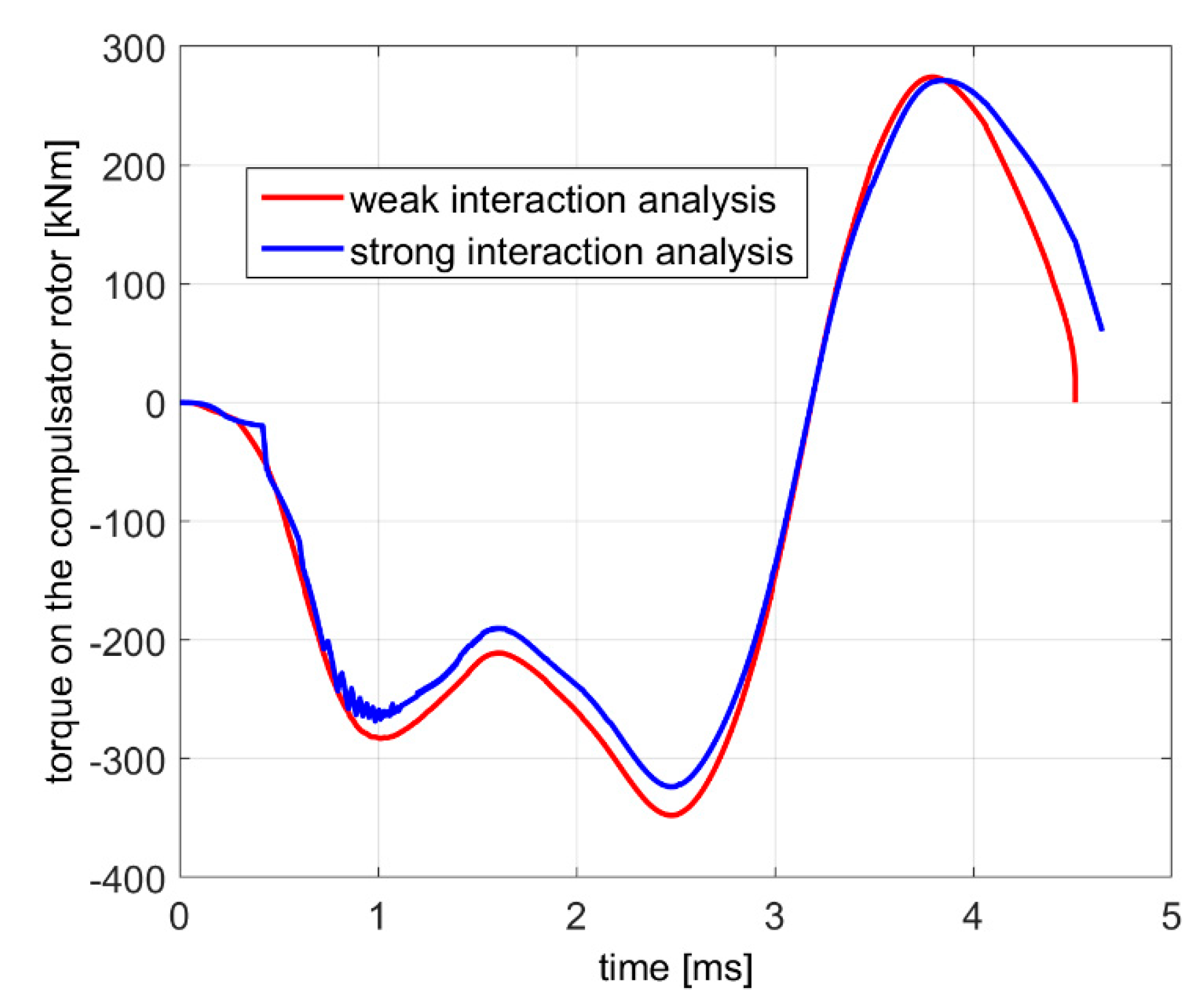
Let us now consider the dynamic quantities on the compulsator.
Figure 13 shows the torque acting on the rotor. As expected the torque is mostly negative, producing a decrease of the speed of the rotor. The figure shows that in the last portion of the launch time, the torque assumes positive values so increasing the velocity and the kinetic energy of the rotor, with respect to their minima.
The instant when the torque changes its sign is roughly the same as the one when the delivered current reaches its maximum. A decreasing current implies a reduction of the magnetic energy stored in the system. Part of this magnetic energy is converted in mechanical energy by increasing the speeds of the rotor of the compulsator and of the armature of the launcher. The remainder increases the temperature of the conductors. The weak interaction analysis produces a smoother waveform than that of the strong interaction one.
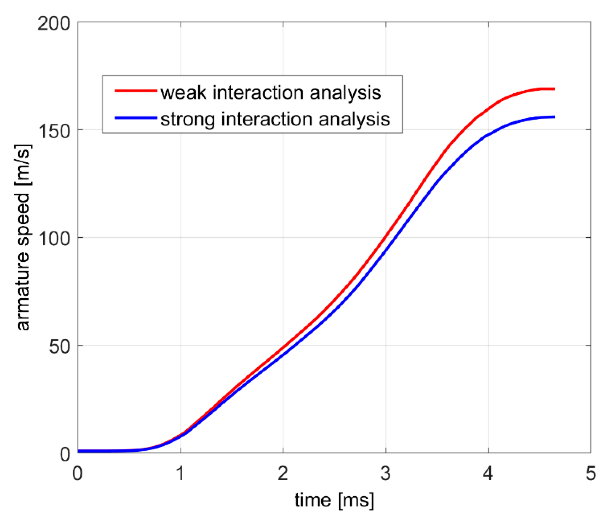
The comparison of the speeds of the armature obtained by the two models is reported in
Figure 14. The weak interaction analysis overestimates the speed of about 10%. The ripple in the thrust force is cancelled by the integration and does not affect the speed waveform produced by the strong interaction analysis.
If a lumped equivalent circuit was used for the compulsator, further errors would appear. These errors will be more relevant if components made up of massive conductors are present in the compulsator (e.g., a conductive shield). In this case, the actual distribution of the currents cannot be predicted a priori. Anyhow, the errors are expected to be lower when compensating concentrated windings are used.
The errors in the exit speed, lead to a wrong estimate of the launch time and therefore on the length of the current pulse. If this happens, the exit of the armature from the launcher could occur in correspondence of a non-zero value of the current, with consequent reduction of the system performance (low efficiency and arcing between armature and rail at the muzzle).
Despite the complexity of the problem EN4EM was able to complete the strong interaction analysis in about 150 min on a desktop computer based on an intel i7 6 core and equipped with 20 GB RAM. The maximum allocated memory was about 6 GB. The weak interaction analysis took about 45 min and required about 3 GB.


