Article

Modal Analysis and Rotor-Dynamics of an Interior Permanent Magnet Synchronous Motor: An Experimental and Theoretical Study

Laboratory of Electrical Machines, Department of Mechatronics, Faculty of Electrical Engineering, University of Ljubljana, Tržaska 25, SI1000 Ljubljana, Slovenia
*
Author to whom correspondence should be addressed.
Appl. Sci. 2020, 10(17), 5881; https://doi.org/10.3390/app10175881
Submission received: 1 August 2020 / Revised: 14 August 2020 / Accepted: 20 August 2020 / Published: 25 August 2020
(This article belongs to the Section Energy Science and Technology)

Abstract

:

Featured Application

One of the major objectives of this study was to comprehensively summarize the key parameters related to the mechanical vibrations response phenomena, which are important when designing rotating electrical machines, based on a case study of an interior permanent magnet (IPM) motor. To this end, the IPM prototype was built and its components examined. The presented findings have important potential application in prediction and prevention of premature failure of electrical machine components, which may occur due to the presence of excessive mechanical vibrations of both stator and rotor.

Abstract

This paper investigates mechanical vibrations of an interior permanent magnet (IPM) synchronous electrical motor designed for a wide range of speeds by virtue of the modal and rotordynamic theory. Mechanical vibrations of the case study IPM motor components were detected and analyzed via numerical, analytical and experimental investigation. First, a finite element-based model of the stator assembly including windings was set up and validated with experimental and analytical results. Second, the influence of the presence of the motor housing on the natural frequencies of the stator and windings was investigated by virtue of numerical modal analysis. The experimental and numerical modal analyses were further carried out on the IPM rotor configuration. The results show that the natural frequencies of the IPM rotor increase due to the presence of the magnets. Finally, detailed numerical rotordynamic analysis was performed in order to investigate the most critical speeds of the IPM rotor with bearings. Based on the obtained results, the key parameters related to mechanical vibrations response phenomena, which are important when designing electrical motors with interior permanent magnets, are provided. The main findings reported here can be used for experimental and theoretical mechanical vibration analysis of other types of rotating electrical machines.

1. Introduction

Interior permanent magnet (IPM) synchronous motors are widely used in various industrial applications such as automotive applications, pumps, compressors, centrifuges and many other fields [1,2,3,4]. The most important advantages of IPM over their counterparts are high power density, high efficiency, wide range and adjustable speed operation, high power factor, and low weight [2].
The interior permanent magnet (IPM) synchronous motor rotors are more mechanically robust as opposed to the surface mounted permanent magnet synchronous motors; however, the permanent magnet-based machines might be in general less mechanically robust compared to induction machines due to the fact that they contain relatively fragile mechanical components, such as permanent magnets and their protecting metal sleeves and aluminum alloy shields for eddy current reduction [2]. These components reduce the rotor stiffness, which may lead to undesirable resonance critical speeds close to the operation range, which need to be precisely calculated and foreseen during the process of the development and design of the electrical machine [2].
The optimal mechanical design of a low vibration, low noise and stable rotational movement interior permanent magnet (IPM) synchronous motor intended for a wide range of operating speeds is a challenging task. This is particularly important for automotive applications as well as in similar industrial sectors in which a wide speed range is needed. For such applications the optimum mechanical vibration response of all motor components has to be carefully foreseen in the design stage. The mechanical structure of both stator and rotor assembly and their components needs to be analyzed in detail in addition to other important physical phenomena such as magnetic and thermal properties. Such complete mechanical analysis should include both static modal analysis for vibration analysis of geometrical and material properties of the machine components and the rotor dynamics in order to investigate the vibration of the rotating parts. The modal analysis of the machines’ stator has already been extensively reported for different types of electrical machines [5,6,7,8,9,10,11,12,13,14], while the rotor dynamic has mostly studied for the mechanical design of high speed machines constructed for special applications [1,2,4,15,16,17,18,19,20,21,22,23,24,25]. To the best of the authors’ knowledge, the complete mechanical analysis of the stator and rotor components of the same machine by the modal and rotor dynamic analysis has not been reported.
In the present study, a complete mechanical analysis of an interior permanent magnet (IPM) synchronous motor designed for a wide range of operating speeds was performed by numerically, analytically and experimentally investigating mechanical vibrations of all stator and rotor components of the electrical motor. One of the major objectives was to derive and comprehensively summarize the key parameters related to mechanical vibrations response phenomena, which is important when designing rotating electrical machines. Specifically, the present study was focused on the static modal and the rotor-dynamic analysis of the IPM components and its assembly. First, a finite element-based model for modal analysis of the IPM stator stack was built and compared with the analytical and experimental results. Second, the numerical modal analysis was performed for the stator with the slot windings and the end-windings and compared to the experimental measurement data. The influence of the presence of the motor housing on the natural frequencies of the stator was analyzed by numerical modal analysis. The numerical and experimental modal analyses were further carried out on the machine rotor assembly in order to investigate the influence of magnets on its mechanical vibration behavior. Finally, a numerical rotor-dynamic analysis was performed in order to investigate the influence of different bearing properties on the critical rotational speeds of the IPM rotor. The critical rotational speeds are presented in Campbell diagrams. The numerical results are compared to the analytical results of the rotor shaft critical speeds. In addition to the IPM motor, the main findings of this study can be used for mechanical vibration analysis of other types of electrical machines.

2. Materials and Methods

In this chapter, the numerical, analytical and experimental methods used for the modal and rotor-dynamics study and analysis will be described.

2.1. Numerical Modeling

The numerical modal analysis and the rotor dynamic analysis were performed using ANSYS Mechanical software (ANSYS 2019 R1, ANSYS, Inc., Canonsburg, USA), which is based on the finite element method (FEM).
First, the static modal analysis for the free-fee vibration condition was performed in order to investigate the structural mechanical vibration characteristics, such as natural frequencies and the modal shapes of the IPM motor components. The numerical modal analysis in the ANSYS software is executed by numerically solving the general system of equations of motion (Equation 1):
[ M ] { ü } + [ C ] { u ˙ } + [ K ] { u } = { F }
where [M], [C] and [K] are matrices of mass, damping and stiffness, respectively, while the vector {u} stands for the unknown modal displacements resulting in the modal shapes to be calculated. The vector {F} represents the external force for modeling the forced mechanical vibration condition (e.g., electromagnetic force).
In our study, the [C] and {F} were set to zero since the mechanical structures are analyzed according to the unforced and un-damped mechanical vibration conditions, as follows:
[ M ] { ü } + [ K ] { u } = { 0 }
Therefore, by considering the zero damping and zero external excitation force, the ANSYS program numerically solves the eigenvalue problem for the free vibration condition according to the following equation:
{ [ K ] ( ω ) 2 [ M ] } { u } = { 0 }
The output solution provides the natural angular frequencies ω (in rad/sec) and the corresponding modal shapes resulting from the calculated modal displacement {u}. The natural frequencies f in Hz are then calculated as f = ω/(2·π). The eigenvectors {u} thus represent the mode shapes of the analyzed IPM mechanical structure when vibrating at the natural frequency f.
In addition to the geometry of the mechanical structure to be analyzed, the key input material parameters needed for the static numerical analysis are: Young’s modulus E (Pa), Poisson’s ratio and mass density ρ (kg/m3) of the materials composing the modeled structure.
In our study, the 3D geometries of the investigated IPM components were preprocessed using the Ansys Space Claim environment in order to describe the geometry of the real IPM motor configurations as accurately as possible. Figure 1 depicts the geometry of the following IPM components/assemblies that were modelled: the motor assembly with the housing (Figure 1a), stator stack with the rotor and the shaft, rotor with magnets and the shaft (Figure 1c), the shaft only (Figure 1d), the stator stack with slot windings and end-windings (Figure 1e), and the stator lamination (Figure 1f). It should be noted that one of the goals of this study was to investigate whether an accurate and fast mechanical vibration analysis can also be done with adequately simplified geometrical and mechanical material properties of the real IPM windings. A simplified stator geometry model was therefore built in the form of solid bodies of slot and end-windings (as shown in Figure 1e) with equivalent mechanical material properties of composite materials assigned based on the experimental and numerical data found in the literature [9]. The accuracy of the modal analysis results was controlled by comparing the numerical results to the experimental measurements performed on the real IPM stator with the distributed windings. This allowed us to validate the simplified numerical model with equivalent geometrical and material properties (Figure 1e), with the goal to reduce the time needed for numerical calculations while still preserving the accuracy of the numerical results. However, one should bear in mind that for the precise magnetic study and/or coupled multi-physics analysis, a more complex numerical model with a more detailed description of the IPM distributed windings (its detailed geometrical and material properties) should be built.
The main geometrical parameters and dimensions are summarized in Table 1. The main mechanical material properties of the modelled IPM motor components are listed in Table 2.
The mechanical material properties of ferromagnetic material M270-35A (Cogent Power Ltd, Surahammar, Sweden) and permanent magnets NdFeB (Arnold Magnetic Technologies AG, Lupfig, Switzerland) listed in Table 2 were taken from the manufacturer data sheets. For the shaft, motor frame, back and front end cover, the built-in material properties from the ANSYS library were assigned to the model since they matched the real materials of the IPM motors. All the mechanical material properties for all motor components were considered as homogeneous and isotropic (i.e., core lamination was neglected). The mechanical material properties such as Young’s modulus E, mass density ρ and Poisson’s ratio of the slot windings and the end-windings were defined in our model based on previous experimental and numerical studies of similar mechanical structures [9]. More precisely, the mechanical properties of the slot and end-winding needed for the structural modal analysis were determined as the equivalent mechanical properties of the composite materials, which consist of enameled wires, insulation sheets and epoxy resin [9]. The equivalent Young’s modulus of the windings, which has previously been experimentally determined as the second order polynomial function of the copper fill factor kcu, was therefore used, according to Equation (4) [9]:
E ( k c u ) = 0.0004 k c u 2 + 0.0212 k c u + 0.694
where the fill factor kcu is the actual cross section of a conductor to the total area of the slot expressed in percent. In general, the fill factor in the conventional machine windings designs spans the range of values 0.35 ≤ kcu ≤ 0.8 [9]. The equivalent mass density ρ e q of a composite material can also be easily expressed as a function of fill factor kcu, according to Equation (5):
ρ e q ( k c u ) = ρ c u     k c u + ρ i n s   ( 1 k c u )
where ρcu and ρins stand for mass density of copper and insulation, respectively.
Using the numerical model proposed in this study and considering Equations (4) and (5), the investigation of the natural frequency dependency on the fill factor kcu (being one of the key parameters in mechanical, magnetic and thermal aspects of the electrical machine design) was carried out. The reference model of slot winding and end-windings was built and analyzed for kcu = 41% [9].
The rotor dynamic analysis implemented into the ANSYS Mechanical was performed by numerically solving the equation of motion, which takes into account the gyroscopic effect of the mechanical system, which can be written as follows:
[ M ] { ü } + ( [ C ] + [ C g y r ] ) { u ˙ } + [ K ] { u } = { F }
where [M], [C] and [K] are structural mass, damping and stiffness matrices, respectively. The natural frequencies of the analyzed system were calculated by setting the right hand side of the equation to zero, hence the excitation force {F} = 0. The [Cgyr] denotes the contribution of the Coriolis effects or the damping matrix contribution due to the gyroscopic effect, which imposes the change in stiffness of the rotating structure, which is reflected into the split of the rotational vibration modes into the forward whirl mode (FW) and backward whirl mode (BW) [16].
The IPM rotor mechanical assembly for which the numerical rotor dynamic analysis was performed is shown in Figure 2. The analyzed IPM rotor assembly with the shaft and bearings is shown in Figure 2a, where the model of the bearing system is implemented in ANSYS as a mechanical connection type defined to the selected shaft locations. The bearings connection type allows for definition of the stiffness and the damping properties of bearings. The equivalent lumped circuit mechanical model of the bearing system (i.e., the spring-damper bearing model) implemented in the ANSYS environment is illustrated in Figure 2b, where k11, k12, k21, k22 are the stiffness coefficients and c11, c12, c21, c22 are the damping coefficients describing the modeled characteristics of the bearings. Figure 2c shows the numerically modeled IPM rotor configuration with shaft, bearings and the load.
The output results of the rotational dynamic analysis in ANSYS Mechanical are provided as numerically computed values of eigenvalues f (Hz) (i.e., natural frequencies, also referred to as whirl frequencies) as a function of the rotational speed Ω (rpm) of the modeled rotating structure (i.e., f(Ω)). This function f(Ω) is referred to as Campbell diagram (named also whirl speed map). The critical speed can be determined from the Campbell diagram at the intersection points of the f(Ω) function with the synchronous spin speed line: f = Ω/60 (i.e., referred to as 1x critical speed) [16,18,22]. The corresponding modal shapes (i.e., lateral and torsional modal shapes, rigid-cylindrical and conical, bending and/or coupled modal shapes) of the rotating structure for each of the whirl frequencies and rotational speeds is also provided in the post processing database. Based on the functional dependency f(Ω), the profiles are displayed in the Campbell diagram and the nature of the corresponding modal shapes and the crucial rotational dynamic properties of the modeled rotating structure can be detected. For example: (1) a strong dependency of the Coriolis effect, which affects the stiffness of the system, is reflected in the split (i.e., bifurcation) of the vibrational rotational modes; (2) the translational rotational modes (i.e., cylindrical rotational modes) are typical for the symmetric mechanical structures; and (3) the presence of torsional critical speeds and torsional vibration modes indicates the adequacy of the selected geometrical and material properties of the modeled structure [16,18,19,20,21,22,23,24,25].
All of the numerical simulations were run at the Laboratory of Electrical Machines, Faculty of Electrical Engineering, University of Ljubljana, Slovenia on a workstation platform HPE Apollo r2800 Gen10 24SFF CTO Chassis with HPE XL1x0r Gen10 Intel Xeon-Gold 6130 (2.1GHz 16-core 125W) processor with eight HPE 32GB (1x32GB) Dual Rank x4 DDR4-2666 units, resulting in 256 GB of RAM (Hewlett Packard Enterprise, USA). The accuracy of the numerical simulations was program controlled via adaptive sizing, connection and finite elements type selection. The final mesh density was created by refining the finite element mesh until the results of the calculated output results changed less than 0.3% (compared to the previous/coarser mesh density) and thus the numerical error was considered negligible. The statistics of the final mesh (i.e., the number of elements and nodes) is given in the results section for each FEM model. The number of degrees of freedom can be estimated by the number of nodes multiplied by the number of dependent variables (i.e., present in all nodes of the 3D FEM model).

2.2. Analytical Analysis

The analytical models can also serve as powerful tools for a rapid analysis of mechanical vibration of the electric motor components [7,10,11,14,20,22]. In this chapter, the practicality of the existing analytical solutions for mechanical vibration analysis of the IPM motor components is presented. First, the analytical solution for the natural frequencies calculation of the IPM stator with and without windings is presented. The practicality of these solutions for the IPM motor was examined by comparing the obtained results to the experimental measurements on the prototyped IPM components. Further, the rotor dynamic analytical solutions for a simple shaft (i.e., the real IPM shaft is approximated with a uniform shaft) and bearings system is presented for calculation of natural frequencies (i.e., transversal, torsional and lateral) and critical speeds of the IPM motor by taking into account the gyroscopic effect. The rotor dynamic analytical solution is used for validation of the IPM numerical model built in this study.

2.2.1. Analytical Solutions for the Stator without Windings

The natural frequencies f [Hz] can be approximately estimated according to Equation (7):
f   1 2 π k s y s t m s y s t ,
where ksyst and msyst stand for the stiffness and the mass of the mechanical system, respectively. According to Equation (7), the natural frequency f increases due to the increase of the stiffness ksyst of the system, which is defined with its equivalent Young’s modulus. Conversely, the natural frequency of the system decreases as its mass increases [9].
In order to analytically estimate the circumferential modal frequencies of the IPM stator, the Jordan’s formula [10] was used, which is valid for circumferential modal shapes m ≥ 2 for the stator stacks without presence of the windings, according to Equation (8):
f m 2 =   m   ( m 2 1 )   T s y   f 0 2   3   R m ( m 2 + 1 ) ,
where m is the circumferential mode number and Tsy and Rm are the thickness and the mean radius of the stator yoke, respectively.
The pulsating modal frequency f0 above is defined as follows:
f 0 =   1 2   π   R m   E ρ s   w ,
where E is the Young’ modulus of the stator material. The parameter w’ in the equation represents the correction weight factor introduced in order to approximate the stator geometry with the geometry of regularly shaped smooth rings, defined as:
w = 1 +   N s p   w p w y ,
where Nsp, wp and wy stand for the number of the stator teeth, weight of the stator tooth, and the weight of the stator yoke, respectively.

2.2.2. Analytical Solutions for the Stator with Windings

In order to analytically estimate the influence of the presence of the slot winding and end windings on the circumferential natural frequencies of the IPM stator, the analytical formula developed by Jordan, Frone and Uner [7], which takes into account the windings, stator teeth, effects of shear, and rotary inertia, was used, as defined by Equation (11):
f m 2 =   m   ( m 2 1 )   a   f 0 ( ( m 2 + 1 )   +   a 2   ( m 2 1 )   ( 4   m 2 +   m 2   d w + 3 ) )
where m is the circumferential mode number, and the coefficient a relates to the thickness and the mean radius Tsy and Rm of the stator yoke, respectively, according to Equation (12):
a = 1 2   3   +   T s y R m .
The f0 is the frequency of the pulsation vibration mode (m = 0), which relates to the Young’s modulus of elasticity of the stator E, density of the stator material ρs, the mean radius of the stator yoke Rm and the factor w according to t Equation (13):
f 0 =   1 2   π   R m   E   ρ s   w .
The factor w in Equations (11) and (13) denotes the weight of the system defined as:
w = 1 +   w w   +   w i   + w p   w y  
where ww, wi, wp, and wy denote the total weights of winding in the slots and end-windings, insulation, stator teeth and stator yoke, respectively.
In order to express the modal frequency f m = 2 and the pulsation frequency f 0 as a function of space winding factor kcu (i.e., f m = 2   ( k c u ) and f 0   ( k c u ) ), Equation (4) should be introduced into Equation (13) and Equation (5) into Equation (14), which yields:
w = 1 +   V w i   ( ρ c u     k c u + ρ i n s   ( 1 k c u ) ) + w p   w y  
Finally, the factor d in Equation (11) is defined as follows:
d = 1 +   91   N s p   A s p   h s p 2   ( w w   +   w i   + w p   ) L s t   R m   w p   T s y   ( 1 3 +   T s y 2   h s y + ( T s y 2   h s y ) 2 )
where Nsp, Asp, hsp and Lst are the number of stator poles, the circumferential cross-sectional area of each stator tooth, the height of the stator pole and the length of the stator stack, respectively.
In addition to the circumferential natural frequencies, the bending natural frequencies should also be investigated when designing electrical machines. For the stator, the importance of the bending frequency depends on the ratio between the diameter and the length of the stator [7,17]. The analytical solution for calculation of the fundamental natural frequency (fn) of a solid bar under a free vibration condition is defined as follows:
f n = a n 2 π   E   I μ L   L s t 4 ,
where E is Young’s modulus, I is inertia, μ L is mass per unit length, Lst is axial length and a n is a numerical constant [17]. According to Equation (17), the bending frequency of a simple solid bar structure depends on the stiffness as well as on the axial length of the bar Lst.

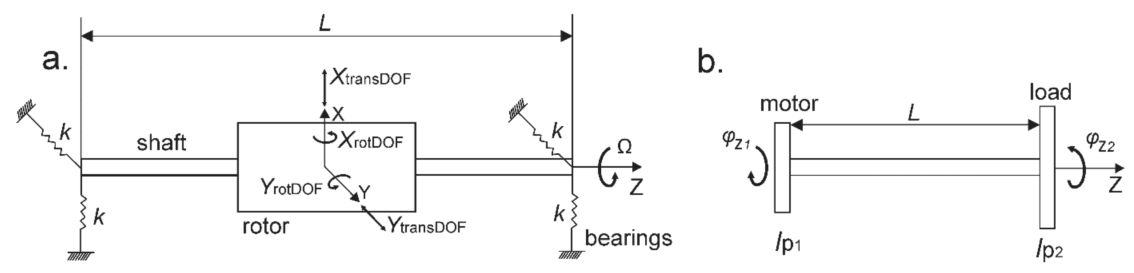
2.2.3. Analytical Calculation of Rotor Critical Speeds, Whirl Natural Frequencies and Torsional Natural Frequencies

The analytical rotor dynamic analysis is presented for simplified rotating mechanical structures as illustrated in Figure 3 for: a long symmetrical rotor-shaft mounted on identical flexible isotropic bearings system for the whirl natural vibration study with gyroscopic effect (Figure 3a) and a two-disc rotor system for torsional vibration study (Figure 3b).
For the long symmetrical rotor mounted on identical flexible isotropic bearings with the stiffness k = k11 = k22, (Figure 3a), the analytical solutions for the natural whirl frequencies and critical rotational speed considering the gyroscopic effect can be derived based on the equations of motion approach, i.e., force and moment equations for the translational and rotational movement, respectively [20,21,22]. Therefore, the analytical solution for the natural frequencies of the rotating rotor on the shaft with the bearing system considering the harmonic motion in four degrees of freedom (4 DOF) (Figure 3a), can be written as follows:
[ m s h   f 2 + 2   k 0 0 0   0 m s h   f 2 + 2   k 0 0   0 0 I d   f 2 + 0.5   k   L 2   I p Ω   ν   0 0 I p   Ω   ν I d   f 2 + 0.5   k   L 2 ] { X t r a n s D O F Y t r a n s D O F X r o t D O F Y r o t D O F }   =   { 0 0 0 0 }
where f is the natural whirl frequency, msh is the mass of the shaft, k is the dynamic parameter (the stiffness) of the isotropic bearings, Ω is the rotational speed, XtransDOF, YtransDOF, XrotDOF, YrotDOF are displacement in the x direction, displacement in the y direction, rotation around the x axis, and rotation around the y axis, respectively (as depicted in Figure 3a), and Ip and Id are the cylinder polar moment of inertia and its diameter moment of inertia, respectively.
The natural frequencies are than calculated from the determinant of the matrix of Equation (18), which yields:
( m s h   f 2 + 2   k ) 2   { ( I d   f 2 + 0.5   k   L 2 ) 2 +   ( I p   Ω   ν ) 2 } = 0 .
By solving Equation (19), four natural frequencies are obtained. The first two (Equation (20)) are pure translational speeds (which result in cylindrical modal shapes) and do not depend on the rotational speed of the rotor (no influence of the gyroscopic effect). This frequency therefore does not split and it is typical for symmetric and perfectly centered rotational systems, describing pure translational rotational motion (i.e., resulting in the cylindrical rotational modal shape) [20,21].
f 1 = f 2 = 1 2 π 2   k m s h
The third and the fourth natural whirl frequency equations are affected by the gyroscopic moment, which typically reflects the dependency of the natural frequency of the rotating mechanical system on the rotational speed of the system. Based on the theory of the rotor dynamics, the critical rotational speeds can appear in the same direction as the direction of the rotor rotation (i.e., forward whirl direction FW) and in the opposite direction compared to the rotation direction of the rotor (i.e., backward whirl direction BW). The value and the direction of the rotation depend on the configuration and the mechanical material properties of the rotor, shaft and the bearings system. Thus, the whirl frequencies typically split into two functional dependencies indicating the forward whirl motion (FW) and backward whirl motion (BW) due to the gyroscopic effect. Analytically computed eigenvalues as a function of the shaft’s rotation speed given in Equation 21 and Equation 22 can be used to draw the Campbell diagram f(Ω).
f 3 ( Ω ) = I p 2   I d   Ω +   k   L 2 2   I d + ( I p 2   I d Ω ) 2
f 4 ( Ω ) = I p 2   I d   Ω + k   L 2 2   I d + ( I p 2   I d Ω ) 2
It is important to note that the forward whirl motion (FW) increases with the increasing rotational speed (Equation 21), while the backward whirl motion (BW) frequency decreases with increasing rotational speed (Equation 22) for the pure tilting motion (i.e., resulting in the conical rotational mode shape). These equations are used for validation of our numerical models of simple shafts but also for the verification of practicality of the simpler equations for rapid estimation of real IPM shafts.

2.2.4. Calculation of Torsional Natural Frequencies

For the free torsional vibration of the two-disc torsional rotor system (Figure 3b) with two different polar mass moments of inertia Ip1 and Ip2 in kgm2, the following system of equations for the simple harmonic motion [21,22,25] was applied:
[ ( G   J L ω 2   I p 1 ) G   J L G   J L ( G   J L   ω 2   I p 2 ) ] { φ z 1 φ z 2 } = { 0 0 }
The torsional stiffness of the shaft kt in Nm/rad can be calculated as:
k t = G J L ,
where G is the modulus of rigidity (shear modulus) in N/m2, L is the length of the shaft and J is the polar second moment of area of the shaft cross-section calculated according to the equation:
J = π 32 D 4
where D is the diameter of the shaft.
The torsional natural frequencies can be calculated based on the nontrivial solution of the equation; hence, by calculating the determinant of the equation, the following torsional natural frequency equation is obtained:
ω 2   { ω 2   I p 1   I p 2   G   J L   ( I p 1 + I p 2 ) } = 0 .
The analytical solution provides the torsional natural frequency f [Hz], i.e., (f = ω/(2·π)) for the two-disc torsional system (if the mass of the shaft is neglected and the discs are considered to be thin), according to Equation (27):
f = 1 2 π ( I p 1 + I p 2 ) k t I p 1 I p 2 .
In this study of torsional natural frequency of the simplified IPM motor with the load, Ip1 and Ip2 stand for the polar mass moment of inertia of the solid rotor and the load, respectively.

2.3. Experimental Measurements

The experimental measurements were performed on the IPM components using the commercial measurement equipment DEWEsoft® (Trbovlje, Slovenia)) in our laboratory settings (Laboratory of electrical machines, Faculty of electrical engineering, University of Ljubljana). The components of the IPM motor on which the experimental modal analysis was performed are shown in Figure 4 (i.e., stator stack only (Figure 4a), stator with the slot winding and end-windings (Figure 4b), rotor without magnets (Figure 4c) and rotor with magnets (Figure 4d)). All of the components of the IPM motor have been prototyped in this study according to the results obtained with the numerical and analytical models described. All components were freely suspended on a cord with neglected mass in order to ensure the free vibration condition. The area marked with white circles in Figure 4a–d indicates the location of the sensor positioned on the IPM component surfaces during the experimental assessment. The reference sensitivity of the impact hammer (Dytran Instruments, Inc., Chatsworth, LA, USA) used was 48.50 mV/Lb.F (Figure 4e). The reference values of the accelerometer sensor sensitivities in X, Y and Z directions were 10.05 mV/g, 9.91 mV/g and 10.08 mV/g, respectively, (Figure 4f). The modal response of the excited mechanical structures was measured via the structural frequency response function (FRF), which typically carries information about the natural frequency and modal damping. The quality of the FRF signal was controlled by appropriate selection of the impact hammer tip, which was selected to ensure as short as possible duration time that the hammer is in contact with the mechanical structure (i.e., IPM motor component). The locations of modal excitation with the hammer were carefully selected in order to comply with the repeatability, reciprocity and linearity of the output signal. The FRF response was measured and analyzed with the specialized Dewesoft X3 (Trbovlje, Slovenia) data acquisition software in order to acquire the natural frequencies of each of the IPM components. The measured FRF signals were further processed and visualized using Matlab R2020a (MathWorks, Natick, MA, USA) software. The obtained results of the natural frequencies were then compared to the results of the numerical and analytical modal analysis performed in this study.

3. Results and Discussion

3.1. Natural Frequencies and Modal Shapes of the Stator with and without Windings

The comparisons of experimental, numerical and analytical output results obtained with modal analysis of the stator stack without windings and with windings are given in Table 3 and Table 4, respectively.
The results of the experimental measurement of modal natural frequencies identified on the stator stack without windings are displayed in Figure 5a, while the experimental results performed on the stator stack with the presence of the slot windings and end-windings are shown in Figure 5b.
The results in Figure 5 show that the natural frequency of the stator with slot winding and end-windings decreased compared to the natural frequencies of the stator stack only.
The front view of the numerically calculated modal shapes (m = 2, m = 3, m = 4, m = 8 and m = 0 - pulsating mode) of the 3D numerical model of stator stack without windings is shown in Figure 6. The normalized total deformations are indicated in the color bar in Figure 6 from minimum (blue color) to maximum (red color). The color bar is also valid for Figure 7, Figure 8, Figure 9 and Figure 10. The results were obtained with the final mesh density consisting of 143,573 finite elements and 250,364 nodes. The 3D numerically calculated modal shapes and their corresponding natural frequencies of the stator with the slot windings and the end-windings are displayed in Figure 7. The results were obtained with the final mesh density consisting of 197,911 finite elements and 323,364 nodes.
The comparison results shown in Table 3 and Table 4 indicate a good agreement between the experimental, numerical and analytical results, which is particularly important for the most critical modal frequency m = 2, at which the highest amplitude is expected.
The results shown in Table 4 indicate that the analytical solution given by Equation 11 can be used for a rapid preliminary calculation of the most critical modal frequency (m = 2) for the IPM stator with the presence of the slot windings and end windings, with 12% difference with respect to the numerical results and 8% difference with respect to the experimental measurements. However, it should be emphasized that the analytical results (Equation 11) can estimate the natural frequencies only for the winding fill factors kcu within the range 0.35–0.45. For fill factors outside this range, the equation gives erroneous results, since it neglects the Young’s modulus of the windings. In order to achieve accurate results of the electrical machine stator natural frequencies with windings with a given fill factor kcu, the equivalent Young’s modulus of composed materials (conductor and insulation) as a function of the fill factor has to be taken into account E(kcu).
Moreover, in certain electrical machines, the stiffness of the slot winding and end-windings are not equal. According to the mechanical properties reported in the literature for the concentrated windings (such as switched reluctance machines), the Young’s modulus of both slot windings and end-windings is equal. On the other hand, the studies on the asynchronous machine windings (i.e., distributed windings), the Young’s modulus of the end-windings (which typically overhang) is higher compared to the Young’s modulus of the windings in the slots, due to the additional stiffening process of the end-windings [6,9].
The E(kcu) and the ρeq(kcu) of the slot and end windings can be successfully taken into account by means of numerical FEM modeling. Therefore, in order to investigate the dependency of the second mode shape natural frequency on the fill factor fm=2(kcu), the numerical model presented in this study with the simplified slot windings and end-windings (Figure 1e) was used by taking into account the Young’s modulus and mass density of windings as a function of fill factor kcu (i.e., (E(kcu) according to Equation 4 and ρeq(kcu) according to Equation 5). A sensitivity analysis was also performed in order to identify the E(kcu) of the real IPM stator, since, in this study, the E of slot windings and end-windings were not directly measured (as stated before, the material properties were taken from the literature [9]). For this purpose, the numerical calculations were done for different kcu values (within the range from 0.35 to 0.8) and different kcu ratios of the end-windings were compared to the kcu of the slot windings (from 0.5·kcu to 2·kcu) (Figure 11). The E(kcu) was identified by comparison of the numerical results with experimental measurements (Figure 5b). In Figure 11, three different cases of mechanical properties of the slot windings versus end-windings are given: (1) slot windings and end-windings with equal kcu; (2) slot windings with kcu and end-windings with 2 kcu; and (3) slot windings with kcu and end-windings with 0.5 kcu.
It should be noted that the results of the sensitivity analysis indicate that best agreement/matching between the numerical and experimental results can be obtained when the fill factor of the end-windings is slightly lower (i.e., around 0.75·kcu) compared to the kcu of the slot winding (Figure 11). However, the equal kcu was kept in both slot and end windings (in the model defined as kcu = 0.41) in order to simplify the numerical model as much as possible, since, in this case, a small difference between the experimental and numerical results was obtained: (i.e., 4.7%, Table 4, m = 2, numerical model: f = 525 Hz vs. experimental measurements f = 500.5 Hz).
Based on this, the modeling approach presented in this study, which proposes a simplified geometry of the slot winding and end-winding as a solid object (Figure 1e) with equivalent mechanical properties of the composite material, was successfully validated with the experimental measurements. More accurate results can be obtained with a more precise definition of all geometrical and material details of the slot and windings, which in turn may require an additional computational time, additional experimental work and/or additional theoretical analysis (e.g., statistical energy analysis) [5].
The output results fm=2(kcu) shown in Figure 11 also indicate that the natural frequency strongly depends on the fill factor kcu, and consequently, the equivalent density ρeq and the stiffness of the stator windings E (Equation 7). The numerical results in Figure 11 also show that the natural frequency of the whole stator-winding assembly increases if the kcu of the end-winding is higher compared to the kcu of the slot windings; on the other hand, the natural frequency of the stator assembly decreases if the kcu of the end-winding is lower compared to the kcu slot windings. These results can also be useful for mechanical vibration analysis of other electrical machine stators that have different stiffnesses of the slot windings and end-windings.

3.2. Influence of Motor Frame/Housing on Natural Frequencies and Modal Shapes

The modal analysis of stator and windings with the presence of the motor frame was also performed in order to investigate its influence on the natural frequencies of the inner structures as well as to investigate the resulting natural frequency of the whole motor assembly. The results displayed in Figure 8 show that the presence of the motor frame, front and back ending, increases the natural frequencies of the whole motor assembly (i.e., the motor frame, front and back ending, stator stack and windings). The results were obtained with the final mesh density consisting of 324,440 finite elements and 597,323 nodes. Mechanical vibration energy is transmitted from the inner structures (predominantly stator stack) to the motor frame and fins, and can be detected as audible noise and vibration. From Figure 8b, the vibrations can be visually seen. This probably means that they can be easily detected by measurement on the real machine. The first frequency at which the motor frame will start vibrating occurs at f = 1382 Hz (Figure 8b), which is also the first detectable natural frequency of the stator stack vibration. Our results show that the motor frame will vibrate only if the stator stack vibrates. The presence of the motor frame will increase the natural frequency of the whole assembly; however, it cannot prevent the separate vibrations of the end-windings at lower frequencies, which are not detectable from the motor frame, as shown in Figure 8a. These results shown in Figure 8a show that at the frequency f = 616 Hz, the end-windings vibrate while the motor frame does not vibrate due to low energy transmitted from the inner structures (stator and windings). Therefore, the end-winding in close proximity to the machine cover vibrates at the frequency f = 616 Hz, which is not detectable if only the stator frame vibration is observed. This effect may result in undesirable mechanical damage of the windings and premature failure, although it is not detectable on the motor frame. This also means that the vibration, which is not in the audible specter, needs to be adequately mitigated. It is therefore necessary to perform detailed modal analysis of the inner structures as well in order to evaluate the vibration extent of all components and thus to design a safe and low vibration motor structure.

3.3. Modal Analysis of the IPM Rotor Configuration

In order to investigate the mechanical vibrations of the rotor configuration and its components, such as magnets and the magnetic barriers, the modal analysis of the IPM rotor without magnets and with magnets was experimentally and numerically performed.
The results of experimental modal measurements are shown in Figure 12, investigated within the frequency range 0 < f < 18 kHz.
Figure 12a shows the experimentally determined natural frequency for the rotor without magnets (only magnetic air barriers are present), while Figure 12b shows the natural frequencies measured on the IPM rotor with the magnets (the magnets are placed into the magnetic air barrier compartments).
The numerically calculated natural frequencies and their corresponding modal shapes are shown in Figure 9. The modal shapes at two different frequencies calculated in the proximity of the measured ones are displayed for each configuration. The modal shapes for the IPM rotor without magnets are displayed at the exiting frequencies f = 9498 Hz and f = 10,924 Hz (Figure 9a, the results were obtained with the final mesh density consisting of 48,791 finite elements and 86,253 nodes). The modal shapes for the IPM rotor with the magnets are displayed at f = 14,832 Hz and f = 15,451 Hz (Figure 9b; the results were obtained with the final mesh density consisting of 54,901 finite elements and 118,299 nodes).
From Figure 9 it can be seen that the modal shape strongly depends on the rotor configuration geometry (i.e., number of magnetic flux barriers and consequently the number of magnetic poles). The natural frequencies of the IPM rotor configuration are higher compared to the natural frequencies of the rotor without magnets due to the presence of the magnets (Figure 9b). Based on the results reported here, the IPM configuration with the magnets results in more uniform modal shape at higher frequencies compared to the rotor configuration without magnets (with the magnetic air flux barriers only). The non-uniform modal shape is obtained at the lower natural frequency f= 9498 Hz - Figure 9a, while a more uniform modal shape (similar to the second modal shape m = 2) is obtained at the higher frequency f = 10,924 Hz.
As shown in Figure 9b, the deformation of the inner radius of the rotor of IPM will be considerably deformed due to the presence of the magnets. The analysis was therefore also performed for the IPM rotor with the shaft in order to investigate whether the deformation of the rotor with magnet will also result in deformation of the shaft (Figure 10). The presence of the shaft results in a lower natural frequency of the while rotor-shaft assembly. The modal analysis showed that the first bending longitudinal model will occur as f = 5212 Hz (Figure 10a), the second bending will occur at f = 5933 Hz (Figure 10b) and the modal shape, which will result in the critical deformation of both the rotor and the shaft, occurs at the frequency f = 18,449 Hz (Figure 10c). The results shown in Figure 10 were obtained with the final mesh density consisting of 107,958 finite elements and 214,752 nodes.

3.4. Results of the Rotordynamic Analysis

The comparison of the analytical and numerical rotor dynamic analysis was first performed on a simple rotor system with isotropic bearings and uniform shaft in order to validate the numerical FEM model built using Ansys Mechanics software. Analytically and numerically computed whirl natural frequencies (i.e., eigenvalues) as a function of the shaft’s rotation speeds f(Ω) are presented in Figure 13 and Table 5.
Good agreement between the analytical and numerical results was obtained for the solid shafts (modelled as a solid bar with a uniform diameter D). For example, for the uniform/solid shaft with dimensions: D = 27 mm and L = 205.7 mm (which correspond to the mean diameter and length of the real IPM shaft, respectively), the following deviations between the numerical and analytical results was obtained: 1.4% for transversal, 0.26% for rotational FW and 0.16% for rotational BW critical speeds (Table 5).
Figure 13a also shows the numerically calculated critical speed for the geometry of the real IPM shaft with non-uniform diameter (red solid line), which is in good agreement with the analytical solution of the uniform IPM shaft approximated with a solid shaft with diameter D = 27 mm (as stated above this is the mean diameter value of the non-uniform real IPM shaft with dimensions 23 mm ≤ D ≤ 31 mm). The obtained difference between the analytically and numerically calculated critical speeds is as follows: transversal 1.38%, rotational FW 4% and rotational BW 5.4%, which is in line with the requirements of the API standards [18]. Such agreement between the analytical (uniform shaft with D = 27 mm, Figure 13a) and numerical results (non-uniform real IPM shaft, red lines in Figure 13a) validates the numerical models proposed in this study and confirms the practicality of the analytical solutions, indicating that they can be used for a rapid preliminary prediction of the critical speeds. (The numerical results show that the non-uniform real IPM shaft was obtained with the final mesh density consisting of 14,438 finite elements and 23,993 nodes).
Further, the investigation of the influence of the dimensions of the shaft (i.e., different diameters) and the bearing properties (i.e., different bearing stiffnesses) on the critical speeds of the rotating mechanical structure was carried out based on the analytical solutions given with Equation (20), (21) and (22). The comparison of the analytically calculated critical speeds for different diameters of the rotor shaft (Figure 13a) indicates that the critical speeds decrease with the increase of the shaft diameter. The comparison of the analytically calculated critical speeds for different bearing stiffnesses indicates that the higher the bearing stiffness, the higher the critical speed of the shaft (Figure 13b). For the IPM shaft analyzed in this study (with a maximum operational speed of 10,000 rpm), this means that the bearings with the k11 = k22 = 106 and k11 = k22 = 107 N/m could be more appropriate compared to the bearings with k11 = k22 = 105 N/m (Figure 13b).
Figure 14 shows the comparison of the analytical and numerical solutions for a simple two-disc rotor system (illustrated in Figure 3) where the first and second disc represent the rotor and the load, respectively. The calculations were done for the different polar masses of inertia of the load Ip2 spanning the range 0.005 kg·m2 < Ip2 < 0.025 kg·m2, while the rotor polar mass of inertia was kept constant at Ip1 = 0.0048 kg·m2 (i.e., equal to the Ip1 of the real/prototyped IPM rotor). The observed difference between the analytical solution (Equation 27) and the numerical results was 5% (Figure 14a), which validated the numerical results (the 5% difference complies with API standards required for a torsional system design [18]). The results in Figure 14a also show that the torsional natural frequencies decrease with the increase of the polar mass of inertia of the load Ip2. The investigation results shown in Figure 14b indicate that the torsional natural frequency of the shaft can be increased by increasing the shaft diameter and decreasing the shaft length.
Finally, the numerical rotordynamic analysis of the real/prototyped IPM rotor configuration (Figure 2) was performed for four different types of bearings in order to investigate the influence of the bearing properties on the rotational critical speeds. The following bearing stiffnesses (i.e., from the soft up to the very stiff bearings) were investigated: k11 = k22 = 105 N/m, k11 = k22 = 106 N/m, k11 = k22 = 107 N/m, and k11 = k22 = 8.2 ·108 N/m (i.e., super precision SKF bearings NN3006KTN/SP). The numerical calculations were done for the no-load (FEM model is shown in Figure 2a) and for the mechanically loaded operational condition (FEM model is shown Figure 2c) of the IPM rotor. The total mass and the moment of inertia of the real IPM rotor are 3.8763 kg and 0.0048 kg·m², respectively.
The calculated critical speeds are given in Table A1 and Table A2 (Appendix A), for no-load and the loaded condition, respectively. The results show the presence of a higher number of critical speeds when the soft bearings are used. Due to the more complex geometry (presence of the rotor with magnets), a higher number of critical speeds is obtained compared to the critical speed profile of the shaft only. The increase of the bearing stiffness results in shifting of critical speeds towards significantly higher values out from the operational range of the machine. The results show that the rotational natural frequencies and critical speeds strongly depend on the properties of the bearings. Therefore, the critical speeds can be reduced or cancelled with the stiffer bearing system. However, the bearing properties do not affect the torsional frequencies, which strongly depend on the material and geometrical properties of the system. Such an example is the speed 7256.6 rpm, as shown in Table A1, which could not be canceled by increasing the stiffness of the bearings system. However, this speed of our model is probably not critical for the real system, since it represents one of the numerical solutions for the no load situation. Similarly, the numerical solution for the rotor with the load appear at the first critical speed value 3790.4 rpm (Table A2), which can be attributed to the non-uniform shape of the shaft.
In order to investigate the critical speeds that may occur in a mechanically loaded IPM rotor system with bearings (Figure 2c), a load with 2.33 times higher moment of inertia Ip2 [kg·m²] compared to the moment of inertia of the IPM rotor was added to the rotor shaft (i.e., Ip2 = 0.0112 kg·m², Ip1 = 0.0048 kg·m² and the inertia ratio Ip2/Ip1 was 2.33). It is well known that the higher the inertia ratio the higher the risk for a suboptimal system performance in terms of resonance. Therefore, such a load was selected in order to investigate one of the most critical scenarios due to the high difference between the two moments of inertia, since it may result in severe consequences such as premature fatigue, shaft bending or crack of the shaft due to resonance with the natural torsional frequencies. The Campbell diagram for the analyzed rotor assembly with the load for four different bearing stiffnesses is shown in Figure 15. The numerical results were obtained with the final mesh density consisting of 132,604 finite elements and 243,733 nodes.
The numerical rotor dynamic simulations identified a larger number of critical speeds at lower motor speeds when the bearings with lower stiffness were used (Figure 15a–c), while for the super precision SKF bearings, only the three critical speeds were identified: 48,774 rpm, 49,683 rpm and 50,393 rpm. The operational speed range of the IPM machine analyzed in this study is defined with the baseline/rated operational speed value of 4000 rpm (at the border between the constant torque and the constant power) up to the maximum speed value of 10,000 rpm (i.e., in the field weakening region). The numerical results shown in Figure 15 indicate that the critical speeds can be shifted out from the operational range of the machine, using bearings with a higher stiffness. It should be also noted that the frequencies shown in Figure 15 are significantly lower compared to the natural frequencies shown in Figure 9 and Figure 10.
The load condition analysis showed that the first torsional frequency appeared at a very high critical speed of 48,774 rpm (which corresponds to the critical natural torsional frequency 812 Hz), and cannot be cancelled or shifted toward higher speeds with stiffer bearings, as shown in Figure 15a–d and Table A2. It should be noted that this torsional speed can also be roughly predicted by using the analytical solution given by Equation 27 (Figure 14a). For the less critical load operational regimes (i.e., for the regimes when the rotor is loaded with the loads with lower polar mass moment of inertia), the critical speeds of the loaded rotor system will further increase (above 48,774 rpm) according to Equation (27), as demonstrated also in Figure 14. It should be noted that the calculated critical torsional speed is significantly higher than the operational speed of the real IPM motor. The last two critical speeds of 49,683 rpm and 50,393 rpm represent the forward and backward critical speeds, which may result in the bending natural frequencies (i.e., the bending rotational modal shapes). These results also indicate that the strong bifurcation shown in Figure 15a–c that occurs due to the presence of the rotor (due to the gyroscopic effect) in the proximity of 900 Hz can be reduced with bearings with a higher stiffness. Based on the obtained results, it can be concluded that the modeling approach presented here can be successfully used for prediction of the most critical speeds that should be avoided during IPM motor operation.

4. Conclusions

We have presented the numerical, analytical and experimental results of modal and rotor-dynamic analysis of interior permanent magnet (IPM) synchronous motor components. The main findings are important in robust design of the IPM motor and can be summarized as follows:
  • The presence of the permanent magnets results in higher natural frequencies of the IPM rotor configuration compared to the natural frequencies of the rotor without magnets. This finding can be useful for robust design of the IPM rotor as well as for the design of synchronous reluctance machines’ rotors without magnets. This is also important for the IMP machine fault detection since the natural frequencies of the rotor with mechanically damaged magnets (and/or partially demagnetized magnets) may be altered (i.e., lower natural frequencies and/or additional natural frequencies might be detected due to the damage).
  • The numerical modeling approach presented in this study proposes a simplified but accurate modeling of the slot winding and end-winding as a solid object with equivalent mechanical properties of the composite material (i.e., conductor and insulations). The proposed model was successfully validated with experimental measurements. The advantage of such a modeling approach is the reduction of the computational time needed for numerical simulations.
  • When an equal fill factor kcu is applied for both end winding and slot winding, the numerically calculated and experimentally measured natural frequencies of the stator with windings differed by 4.7%. This finding might be particularly important when coupling mechanical analysis with magnetic and thermal analysis of the electrical machine, since the kcu of the end windings is usually difficult to determine.
  • The presence of the slot windings and end-winding decreases the natural frequency of the stator assembly. This finding can be also important for analysis of mechanical vibrations imposed by insertion of mechanical supporting structures in order to reduce the mechanical vibrations of the whole stator assembly.
  • The presence of the motor housing results in the higher natural frequencies of the motor assembly. The numerical modal analysis of the stator assembly with housing revealed that certain natural frequencies of the end-windings were excited even though the mechanical vibrations of the motor housing/frame (dictated by mechanical vibration of the stator) were not observed/detected, which is important in prevention of premature damage of windings.
  • The rotor dynamic analysis, taking into account the gyroscopic effect, showed that the bearings with higher stiffness contribute to the increase of the critical speeds and their elimination from the operation range of the analyzed IMP rotor. The models show that a strong bifurcation was present due to the presence of the rotor with magnets compared to the rotor-dynamic shaft only. The calculated torsional critical speeds of the IPM rotor are significantly higher compared to the maximum operational speed, confirming the safe design of the IPM rotor analyzed in this study. The proposed rotor-dynamic numerical models of the IPM rotors were successfully validated with the analytical solutions.
Further mathematical modeling of the IPM motor will focus on coupled physical phenomena including mechanical vibration effects shown in this study coupled with the magnetic, electrical and thermal effects being important in robust and safe design of the e-machine rotors. Further experimental research work will also include the experimental rotor-dynamic analysis.
The results reported here may have important implications in design of mechanically safe and reliable operation of the IPM motors and other rotational electrical machines in order to predict excessive mechanical vibrations and avoid the premature fatigue or e-machine failure.

Author Contributions

Conceptualization, S.Č. and D.M.; Formal analysis, S.Č. and D.M.; Investigation, S.Č. and D.M.; Methodology, S.Č. and D.M.; Writing – original draft, S.Č.; Writing – review & editing, S.Č. and D.M. All authors have read and agreed to the published version of the manuscript.

Funding

This work was supported by the EU project OBELICS, which received funding from the European Union’s Horizon 2020 research and innovation programme under Grant Agreement no. 76950.

Conflicts of Interest

The authors declare no conflict of interest.

Appendix A

Table A1. Critical speeds of IPM rotor under the no-load condition.
Bearingsk 11 = k12 = 105 N/m Bearingsk 11 = k12 = 106 N/m Bearingsk 11 = k12 = 107 N/m Bearingsk 11 = k12 = 8.2·108 N/m
NN3006KTN/SP
Critical Speed
Ω (rpm)
Whirl Dir.Critical Speed
Ω (rpm)
Whirl Dir.Critical Speed
Ω (rpm)
Whirl Dir.Critical Speed
Ω (rpm)
Whirl Dir.
1751BW5520.5 FW////
1751FW5520.9 BW////
7256.6BW *7256.7 BW7256.7 BW7256.7 BW
6080.8 BW11,256 BW17,003BW63,246BW
14,373FW25,319FW17,005FW64,372FW
////32,130BW//
////72,766FW//
* numerical solution of the free no loaded mechanical system which is not considered as critical.
Table A2. Critical speeds of IPM rotor with the load.
Bearingsk 11 = k12 = 105 N/m Bearingsk 11 = k12 = 106 N/m Bearingsk 11 = k12 = 107 N/m Bearingsk 11 = k12 = 8.2·108 N/m
NN3006KTN/SP
Critical Speed
Ω [(rpm)
Whirl Dir.Critical Speed
Ω (rpm)
Whirl Dir.Critical Speed
Ω (rpm)
Whirl Dir.Critical Speed
Ω (rpm)
Whirl Dir.
842 BW//////
844 FW//////
2646 BW2493BW/// /
3138 FW2511FW////
3790 BW3790 BW3790BW3790BW
48,774 FW6245BW7721BW48,774BW
36,476 BW7378FW7776FW49,683FW
//48,774FW17,541BW50,393BW
//36,800BW21,138FW//
////48,774FW//
////40,084BW//

References

  1. Gerada, D.; Mebarki, A.; Brown, N.L.; Gerada, C.; Cavagnino, A.; Boglietti, A. High-Speed Electrical Machines: Technologies, Trends, and Developments. IEEE Trans. Ind. Appl. 2014, 61, 2946–2959. [Google Scholar]
  2. Huang, Z.; Le, Y. Rotordynamics modelling and analysis of high-speed permanent magnet electrical machine rotors. IET Electr. Power Appl. 2018, 12, 1104–1109. [Google Scholar]
  3. Breznik, M.; Goričan, V.; Hamler, A.; Čorović, S.; Miljavec, D. Analysis and identification of influential phenomena on iron losses in embedded permanent magnet synchronous machine. J. Electr. Eng. 2017, 68, 23–30. [Google Scholar]
  4. Ramarathnam, S.; Mohammed, A.K.; Bilgin, B.; Sathyan, A.; Dadkhah, H.; Emadi, A. A Review of Structural and Thermal Analysis of Traction Motors. IEEE Trans. Transp. Electrif. 2015, 1, 255–265. [Google Scholar] [CrossRef]
  5. Delaere, K.; Iadevaia, M.; Heylen, W.; Sas, P.; Hameyer, K.; Beimans, R. Statistical energy analysis of acoustic noise and vibration for electric motors: transmission from air gap field to motor frame. In Proceedings of the Conference Record of the 1999 IEEE Industry Applications Conference. Thirty-Forth IAS Annual Meeting (Cat. No.99CH36370), Phoenix, AZ, USA, 3–7 October 1999. [Google Scholar]
  6. Ishikawa, T. Analysis of Natural Frequency, Radial Force and Vibration of Induction Motors Fed by PWM Inverter, Edited volume: Induction Motors - Modelling and Control; Rui Esteves, Araújo, Ed.; IntechOpen Limited: London, UK, 2012. [Google Scholar]
  7. Anwar, M.N.; Husain, I. Radial Force Calculation and Acoustic Noise Prediction in Switched Reluctance Machines. IEEE Trans. Ind. Appl. 2000, 36, 1589–1597. [Google Scholar]
  8. Tang, Z.; Pillay, P.; Omekanda, A.M.; Li, C.; Cetinkaya, C. Young’s Modulus for Laminated Machine Structures with Particular Reference to Switched Reluctance Motor Vibrations. IEEE Trans. Ind. Appl. 2004, 40, 748–754. [Google Scholar] [CrossRef]
  9. Pupadubsin, R.; Steven, A.; Widmer, J.D.; Mecrow, B.C. Mechanical Material Properties for Structural Simulation Model of Switched Reluctance Machines. In Proceedings of the 2016 XXII International Conference on Electrical Machines (ICEM), Lausanne, Switzerland, 4–7 September 2016. [Google Scholar]
  10. Jordan, H. Geräuscharme Elektromotoren: Lärmbildung und Lärmbeseitigung bei Elektromotoren; Essen: Girardet, Germany, 1950. [Google Scholar]
  11. Lecointe, J.P.; Romary, R.; Brudny, J.F.; Czapla, T. Five methods of stator natural frequency determination: Case of induction and switched reluctance machines. Mech. Syst. Signal. Process. 2004, 18, 1133–1159. [Google Scholar] [CrossRef]
  12. Cai, W.; Pillay, P.; Tang, Z. Impact of stator windings and end-bells on resonant frequencies and mode shapes of switched reluctance motors. IEEE Trans. Ind. Appl. 2002, 38, 1027–1036. [Google Scholar] [CrossRef] [Green Version]
  13. Lin, C.; Fahimi, B. Prediction of acoustic noise in switched reluctance motor drives. IEEE Trans. Energy Convers. 2014, 29, 250–258. [Google Scholar] [CrossRef]
  14. Corovic, S.; Benedetic, R.; Miljavec, D. Modal Analysis of Different Stator Configurations to Mitigate Electromagnetically Excited Audible Noise and Vibrations of Switched Reluctance Motors. ACES J. 2017, 32, 1089–1097. [Google Scholar]
  15. Hong, D.K.; Woo, B.C.; Koo, D.H. Rotordynamics of 120 000 r/min 15 kW Ultra High Speed Motor. IEEE Trans. Mag. 2009, 45, 2831–2834. [Google Scholar] [CrossRef]
  16. Swanson, E.; Powell, C.D.; Weissman, S. A practical review of rotating machinery critical speeds and modes. Sound Vib. 2005, 39, 10–17. [Google Scholar]
  17. Genta, G. ibration of Structures and Machines, 3rd ed.; Springer: New York, NY, USA, 1999. [Google Scholar]
  18. Wang, Q.; Feese, T.D.; Pettinato, B.C. Torsional Natural Frequencies: Measurement vs. Prediction. In Proceedings of the Forty-Second Turbomachinery Symposium, Houston, TX, USA, 30 September–3 October 2013. [Google Scholar]
  19. Kalita, M.; Kakoty, S.K. Analysis of whirl speeds for rotor-bearing systems supported on fluid film bearings. Mech. Syst. Sig. Process. 2004, 18, 1369–1380. [Google Scholar] [CrossRef]
  20. Friswell, M.; Penny, J.; Garvey, S.; Lees, A. Free Lateral Response of Simple Rotor Models. In Dynamics of Rotating Machines; Cambridge Aerospace Series; Cambridge University Press: Cambridge, UK, 2010; pp. 76–123. [Google Scholar]
  21. Friswell, M.; Penny, J.; Garvey, S.; Lees, A. Axial and Torsional Vibration. In Dynamics of Rotating Machines; Cambridge Aerospace Series; Cambridge University Press: Cambridge, UK, 2010; pp. 383–419. [Google Scholar]
  22. Tiwari, R. Rotor Systems: Analysis and Identification; CRC Press Taylor&Francis Group, LLC: New York, NY, USA, 2018. [Google Scholar]
  23. Badshah, S.; Naeem, A.; Rafique, A.F.; Haq, I.U.; Malik, S.A. Numerical Study on the Critical Frequency Response of Jet Engine Rotors for Blade-Off Conditions against Bird Strike. Appl. Sci. 2019, 9, 5568. [Google Scholar] [CrossRef] [Green Version]
  24. Spagnol, J.; Wu, H.; Yang, C. Application of Non-Symmetric Bending Principles on Modelling Fatigue Crack Behaviour and Vibration of a Cracked Rotor. Sci. Appl. Sci. 2020, 10, 717. [Google Scholar] [CrossRef] [Green Version]
  25. Mudau, T.; Field, R.M. Rotordynamic Analysis of the AM600 Turbine-Generator Shaftline. Energies 2018, 11, 3411. [Google Scholar] [CrossRef] [Green Version]
Figure 1. The 3D geometry of the interior permanent magnet IPM motor: (a) stator, rotor and shaft with the housing; (b) stator, rotor with magnets and the shaft; (c) rotor with magnets and shaft; (d) shaft only; (e) stator with windings; (f) dimensions of the stator lamination sheet.
Applsci 10 05881 g001
Figure 2. The geometry of the interior permanent magnet IPM motor preprocessed for the numerical rotor dynamic analysis: (a) the rotor structure with shaft and the bearings; (b) the spring-damper bearing model (k11, k12, k21, k22 are the stiffness coefficients and c11, c12, c21, c22 are the damping coefficients); (c) model of the loaded IPM rotor structure with the shaft and the bearings.
Applsci 10 05881 g002
Figure 3. Illustration of: (a) a long symmetrical rotor mounted on identical flexible isotropic bearings and (b) a two-disc rotor system for torsional vibration study.
Applsci 10 05881 g003
Figure 4. The prototyped components of the IPM motor, on which the experimental modal analysis was performed: (a) stator; (b) stator with slot windings and end-windings; (c) rotor without magnets and (d) rotor with permanent magnets, (e) impact hammer and (f) accelerometer sensor. The white circles indicate the position of the sensor. The displayed IPM components were prototyped in collaboration with the Slovenian company Kolektor Group d.o.o.
Applsci 10 05881 g004
Figure 5. Experimental results of natural frequencies measured for: (a) stator stack without windings and (b) stator stack with the slot windings and end-windings.
Applsci 10 05881 g005
Figure 6. Front view of the 3D numerical model of the stator stack; calculated natural frequencies and their corresponding modal shapes: (a) m = 2, (b) m = 3, (c) m = 4, in (d) m = 8 and (e) m = 0 (pulsating mode). The normalized total deformations are indicated from minimum (blue color) to maximum (red color).
Applsci 10 05881 g006
Figure 7. Numerically calculated modal shapes with the model of stator with slot and end-windings at the natural frequencies: (a) f = 525 Hz (m = 2), (b) 754 Hz, (c) f = 1393 Hz, (d) f = 1762 Hz and (e) f = 5113 Hz (pulsating modal shape m = 0).
Applsci 10 05881 g007
Figure 8. The calculated modal shapes of the IPM motor with the presence of the whole motor frame at the natural frequencies: (a) f = 616 Hz and (b) f = 1382 Hz. The stator frame in the lower figure is hidden in order to visualize the inner structure (i.e., the stator with windings).
Applsci 10 05881 g008
Figure 9. Results of the numerical modal analysis simulations performed for: (a) rotor without magnets and (b) rotor with magnets - IPM rotor. The deflections are indicated from minimum (blue color) to maximum (red color).
Applsci 10 05881 g009
Figure 10. Numerical modal analysis of the IPM rotor with magnets and the shaft assembly: (a) the first bending mode f = 5212 Hz; (b) the second bending mode f = 5933 Hz; (c) the deformation of rotor and shaft f = 18,449 Hz. The deflections are indicated from minimum (blue color) to maximum (red color).
Applsci 10 05881 g010
Figure 11. The numerically calculated dependency of the second modal natural frequency on the fill factor fm = 2(kcu) for 1) the slot windings with kcu and end-windings with 2 ·kcu; 2) equal kcu is applied to both slot winding and end-windings; and 3) slot windings with kcu and end windings with 0.5 ·kcu.
Applsci 10 05881 g011
Figure 12. The results of the experimental modal analysis: (a) rotor without magnets and (b) rotor with magnets.
Applsci 10 05881 g012
Figure 13. Comparison of Campbell diagrams and critical speeds: (a) analytically calculated for different shaft diameters and the numerical results for the real non uniform IPM motor shaft geometry (all the calculations are done for the bearings stiffness k11 = k22 = 106 N/m) and (b) analytically calculated for different properties of bearings (all shafts are L = 207.5 mm long).
Applsci 10 05881 g013
Figure 14. Dependency of the torsional natural frequencies and critical speeds on the: (a) different polar mass of inertia Ip2 of the load (0.005 kg·m2 < Ip2 < 0.025 kg ·m2) at the constant Ip1 of the rotor being Ip1 = 0.0048 kg·m2 (for the IPM rotor: D = 31 mm and L = 80 mm) and (b) different lengths and diameters of the shaft.
Applsci 10 05881 g014
Figure 15. Critical speeds of the IPM rotor with the load represented in Campbell diagrams numerically calculated Figure 9. (a) k22 = 105 N/m, (b) k11 = k22 = 106 N/m, (c) k11 = k22 = 107 N/m, and (d) k11 = k22 = 8.2 × 10⁸ N/m.
Applsci 10 05881 g015
Table 1. Geometrical properties of the IPM components.
Stator Length90 mm
Inner Radius of the Stator 50.7 mm
Outer Diameter of the Stator 90 mm
Stator Teeth Length29.3 mm
Number of Stator Slots36
Height of the End Windings40 mm
Rotor Length90 mm
Rotor Outer Radius50 mm
Rotor Inner Radius15.5 mm
Length of the Shaft207.5 mm
Table 2. The mechanical material properties of the IPM components.
The Motor ComponentMaterialMass Density ρ ([kg/m3)Young’s Modulus (Pa)Poisson’s Ratio
StatorM270-35A76502 × 10110.3
RotorM270-35A76502 × 10110.3
Permanent MagnetsNdFeB75001.6 × 10110.24
ShaftSteel [Ansys Built-in Library]78502 × 10110.3
The Slot Windings and the End-WindingsEquivalent Mechanical Properties of the Cooper and the Insulation [9]43734.97 × 1080.343
Motor Frame/Housing, Back and Front End CoverAluminum Alloy [Ansys Built-in Library]27707.1 × 10100.33
Table 3. Comparison of experimental, numerical and analytical results for the stator without windings.
***f (Hz), m = 2f (Hz), m = 3f (Hz), m = 4f (Hz), m = 0f (Hz), m = 8
Experiments625.615932652//
Numerical, FEM63516372657686814,534
Analytical, Equation (8)61317343325677514,285
Table 4. Comparison of experimental, numerical and analytical results for the stator with windings.
***f (Hz), m = 2f (Hz)f [Hz]f (Hz), m = 0
Experiments500.5695.81315.3/
Numerical, FEM52575413935113
Analytical, Equation (11)458.7//5066.4
Table 5. Comparison of analytical and numerical results (IPM shaft with k11 = k22 = 106 N/m, L = 205.7 mm).
Critical SpeedTransversal Ω [(rpm)FW Rotational Ω (rpm)BW Rotational Ω (rpm)
Analytical-Uniform IPM Shaft D = 27mm13,99024,40023,780
Numerical-Uniform IPM Shaft D = 27mm13,79024,33623,741
Numerical-Non-Uniform IPM Shaft 23 mm ≤ D ≤ 31 mm (Dmean = 27 mm)14,18423,41722,479

