Article

A Novel Iterative Linear Matrix Inequality Design Procedure for Passive Inter-Substructure Vibration Control

by
Josep Rubió-Massegú
1,
Francisco Palacios-Quiñonero
1,*,
Josep M. Rossell
1 and
Hamid Reza Karimi
2
1
Department of Mathematics, Universitat Politècnica de Catalunya, EPSEM, Av.Bases de Manresa 61–73, 08242 Manresa, Spain
2
Department of Mechanical Engineering, Politecnico di Milano, via La Masa 1, 20156 Milan, Italy
*
Author to whom correspondence should be addressed.
Appl. Sci. 2020, 10(17), 5859; https://doi.org/10.3390/app10175859
Submission received: 25 July 2020 / Revised: 17 August 2020 / Accepted: 20 August 2020 / Published: 24 August 2020
(This article belongs to the Special Issue Passive Seismic Control of Structures with Energy Dissipation Systems)

Abstract

:
In vibration control of compound structures, inter-substructure damper (ISSD) systems exploit the out-of-phase response of different substructures to dissipate the kinetic vibrational energy by means of inter-substructure damping links. For seismic protection of multistory buildings, distributed sets of interstory fluid viscous dampers (FVDs) are ISSD systems of particular interest. The connections between distributed FVD systems and decentralized static output-feedback control allow using advanced controller-design methodologies to obtain passive ISSD systems with high-performance characteristics. A major issue of that approach is the computational difficulties associated to the numerical solution of optimization problems with structured bilinear matrix inequality constraints. In this work, we present a novel iterative linear matrix inequality procedure that can be applied to obtain enhanced suboptimal solutions for that kind of optimization problems. To demonstrate the effectiveness of the proposed methodology, we design a system of supplementary interstory FVDs for the seismic protection of a five-story building by synthesizing a decentralized static velocity-feedback H controller. In the performance assessment, we compare the frequency-domain and time-domain responses of the designed FVD system with the behavior of the optimal static state-feedback H controller. The obtained results indicate that the proposed approach allows designing passive ISSD systems that are capable to match the level of performance attained by optimal state-feedback active controllers.

1. Introduction

Nowadays, it is generally accepted that passive vibration control can provide effective solutions for advanced seismic protection of buildings and civil structures [1,2]. Broadly speaking, those solutions can be classified into three main categories: base isolation (BI), tuned dampers (TDs) and inter-substructure dampers (ISSDs) [3]. Typical implementations of that kind of passive vibration control strategies for seismic protection of multistory buildings are schematically displayed in Figure 1.
BI systems use a layer of flexible isolation elements to reduce the ground-to-structure transmission of the seismic disturbance. The main drawback of BI systems is the large base displacements produced by strong earthquakes, which can require the inclusion of sophisticated control strategies to achieve a proper trade-off between the desired level of seismic isolation and the base-displacement constraints [4,5,6,7].
TDs are auxiliary vibrational devices that are attached to the structural system to absorb and dissipate a significant fraction of the structural kinetic energy induced by the seismic excitation. TD systems include classical tuned mass dampers (TMDs) [8] and a variety of other configurations as pendulum TMDs [9], tuned liquid dampers [10] and particle tuned mass dampers [11]. In seismic protection of multistory buildings, the effectiveness of passive TD systems can be compromised by a number of relevant factors, as large size and mass requirements, poor performance against broad-band seismic excitations, and detrimental effects of soil-structure interactions. Frequently, those limitations are addressed by considering enhanced hybrid TD control systems with active or semiactive elements [12,13]. Other solutions include hybrid combinations of TD and BI systems [14].
ISSD systems take advantage of the out-of-phase vibrational response of different parts in compound structures (for example, adjacent stories in multistory buildings) and use energy-dissipation devices as inter-substructure links to increase stability and mitigate the overall seismic response of the structure. Energy-dissipation ISSD links can be implemented using a wide variety of damping elements [2], including metallic dampers [15], friction dampers [16], viscoelastic dampers [17] and fluid viscous dampers (FVDs) [18]. It is also possible to design distributed ISSD systems with TD characteristics by considering inerter elements, which are a promising new class of light and compact two-terminal TD devices [19]. Passive ISSD systems are simple, reliable, robust, technologically feasible, easy to install and maintain, and can operate without external power sources [17,18]. Moreover, properly designed passive ISSD systems can provide a high level of seismic protection, being able to match the performance of active or semiactive feedback control systems [20]. In this case, a major difficulty is to design optimal configurations for the distributed ISSD elements. That issue has motivated a notable theoretical and computational research activity and comprises two challenging problems: (i) optimal tuning, which aims at determining a suitable set of parameter values for a given distribution of the ISSD elements; and (ii) optimal allocation, which seeks for optimal distributions of the damping links in sparse ISSD systems. Recent works in that line include ISSD designs based on a wide variety of optimization objectives, such as structural performance [21], energy dissipation [22], total-building performance [23], retrofitting cost [24] and structural reliability [25]. Advanced ISSD designs consider soil-structure interactions [26], irregular 3D structures [21] and multi-building problems [27,28]. Enhanced design strategies include simplifying procedures to deal with the high computational cost in nonlinear studies [29], design methodologies based on active control approaches [30,31] and special seismic excitation schemes [32]. Relevant aspects associated to practical implementations are discussed in [33,34].
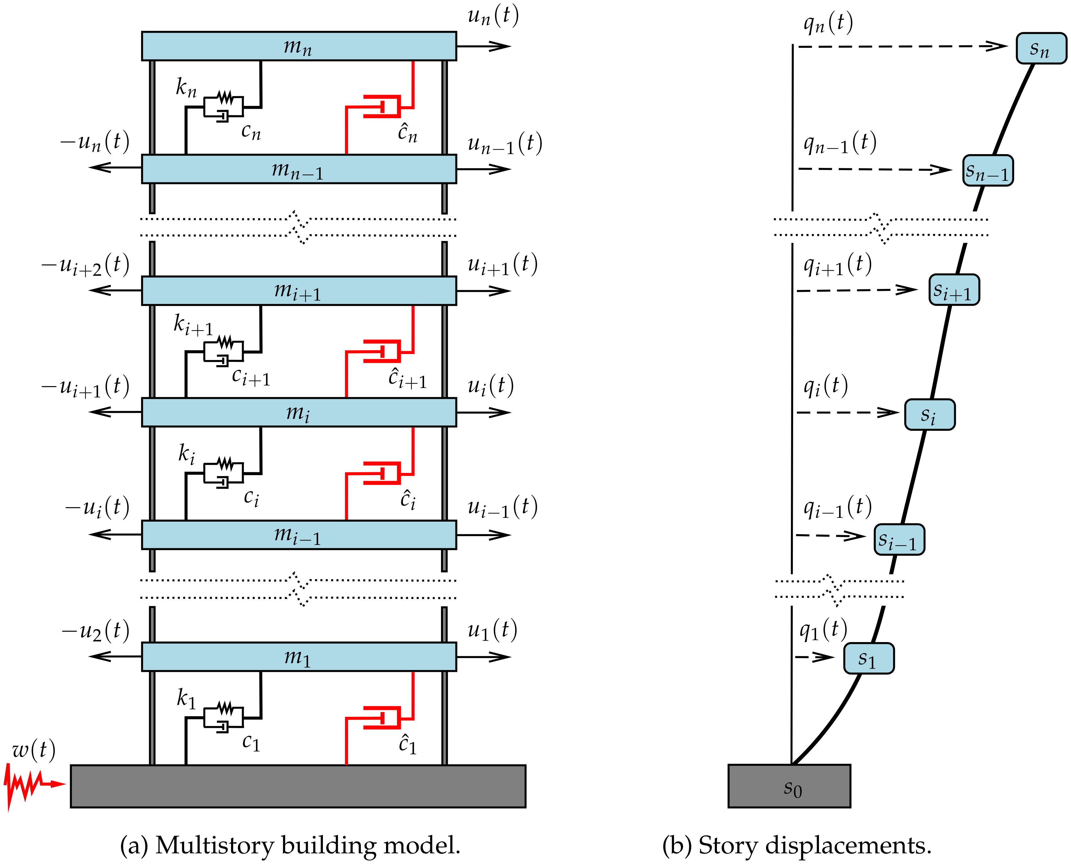
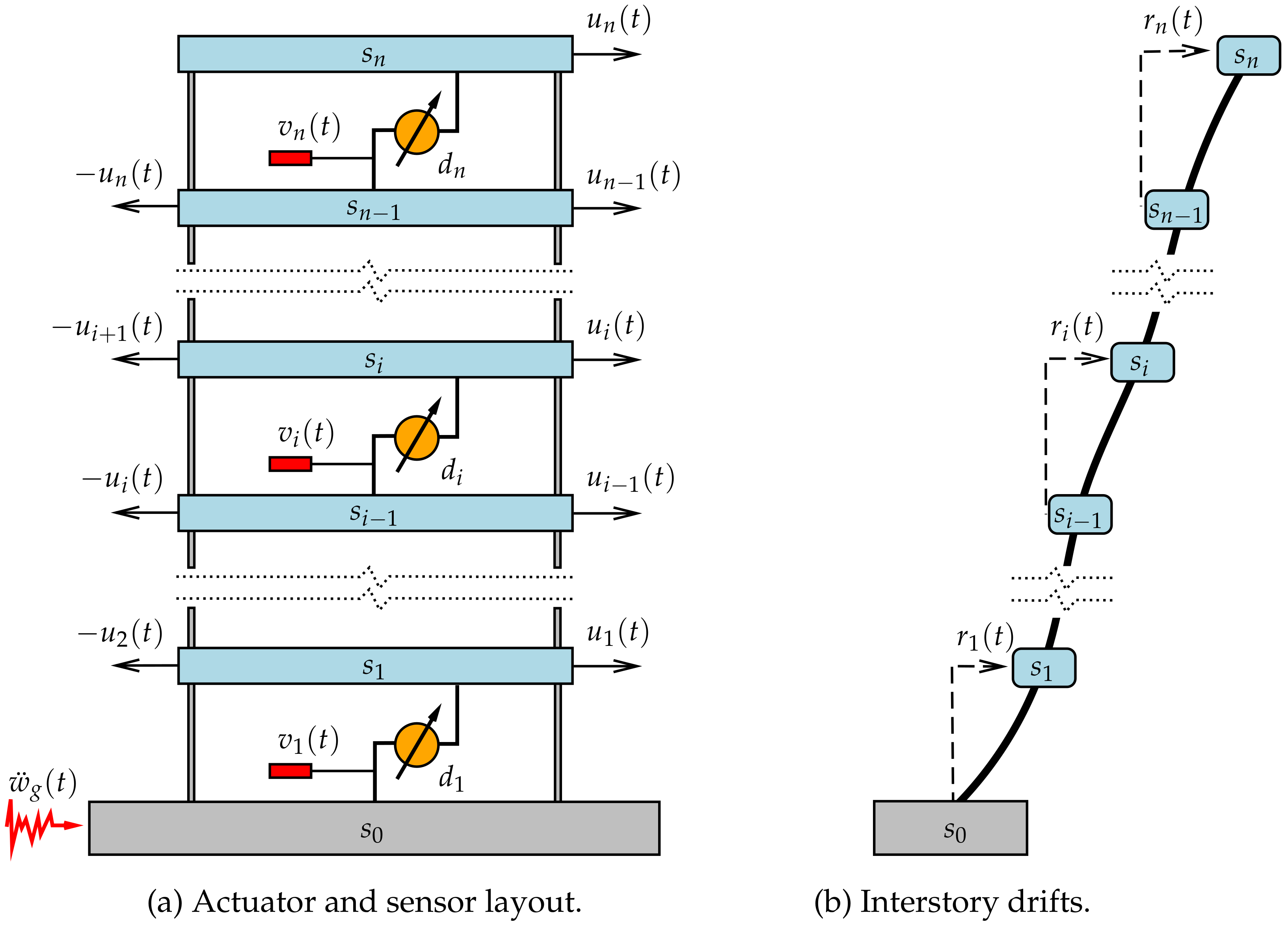
In this paper, we present an advanced computational procedure to design distributed systems of interstory FVDs with high-performance characteristics. The proposed design methodology exploits the connections between systems of distributed interstory FVDs (see Figure 2a) and decentralized static velocity-feedback (SVF) control systems with ideal interstory force-actuation devices and collocated interstory-velocity sensors (see Figure 3a). That approach allows casting the optimal tuning of passive FVD systems as a decentralized static output-feedback (SOF) controller-design problem, which can be formulated as a structured optimization problem with bilinear matrix inequality (BMI) constraints. The BMI optimization problem can later be converted into a structured linear matrix inequality (LMI) optimization problem by means of a suitable transformation of variables, which contains a matrix L whose values can be arbitrarily selected to improve the feasibility and effectiveness of the computational method [35,36]. That line of solution has been applied with positive results to the design of interstory FVD systems and hybrid interstory-interbuilding FVD systems in multibuilding problems [20,31,37]. Preliminary works with a null L-matrix revealed feasibility issues in the LMI optimization problem that were partially solved by introducing a numerical perturbation in the state-space model [35,37]. Improved feasibility results have been obtained with more advanced L-matrix choices that use numerical data provided by the optimal state-feedback controller [38]. However, that approach has the computational drawback of requiring the previous design of a full-state feedback controller [20,31].
The main contribution of the present work is a novel iterative linear matrix inequality (ILMI) procedure that generates a sequence of improved structured SOF controllers by means of a smart choice of the L-matrices. Compared with previous works [20,31,35,37], the proposed ILMI procedure allows a more effective treatment of the feasibility issues, which are now circumscribed to the initial step and separated from the optimality requirements. The modeling aspects are covered in Section 2, where we examine the connections between systems of interstory FVDs and decentralized SVF active controllers, and provide a state-space model for a multistory building equipped with a system of ideal interstory force-actuation devices and a set of collocated interstory-velocity sensors. The details of the ILMI procedure are discussed in Section 3, where we introduce a suitable LMI formulation for structured SOF H controllers, provide a formal proof of the correct definition of the iterates, and present a solution for the initialization step. In Section 4, the proposed design methodology is applied to compute the damping constants of a system of interstory FVDs for the seismic protection of a five-story building. For the obtained FVD system, the frequency response function (FRF) characteristics and the time-domain responses produced by the full-scale El Centro 1940 seismic record are studied and compared with the behavior of the optimal static state-feedback H controller. The results in that section demonstrate the effectiveness of the proposed ILMI procedure and the high-performance characteristics of the designed passive ISSD system.

2. Connections between Interstory FVDs and Decentralized Velocity-Feedback Controllers

Let us consider the n-story building model schematically depicted in Figure 2a where m i , k i and c i respectively denote the mass, stiffness and damping coefficients of the ith story, and the red dashpots represent a system of supplemental interstory FVDs with damping constants c ^ i , i = 1 , , n . The interstory FVD implemented in the ith building-level produces a resistant force
u i ( t ) = c ^ i q ˙ i ( t ) q ˙ i 1 ( t ) ,
where q 0 ( t ) 0 , q i ( t ) , i = 1 , , n is the top-level displacement of the ith story s i with respect to the ground level s 0 (see Figure 2b), and q ˙ i ( t ) is the time derivative of q i ( t ) .
To illustrate the connections between interstory FVDs and decentralized SVF controllers, let us assume that the building is equipped with a system of interstory force-actuation devices d i , i = 1 , n . As schematically displayed in Figure 3a, the actuation device d i produces opposed control forces of magnitude | u i ( t ) | on the adjacent stories s i and s i 1 . The dynamical response of the controlled building can be described by the second order model
M q ¨ ( t ) + C d q ˙ ( t ) + K s q ( t ) = P n u ( t ) M [ 1 ] n × 1 w ¨ g ( t ) ,
where q ( t ) = [ q 1 ( t ) , , q n ( t ) ] T is the vector of story displacements with respect to the ground; u ( t ) = [ u 1 ( t ) , , u n ( t ) ] T is the vector of control actions; w ¨ g ( t ) is the seismic ground-acceleration disturbance; M R n × n , C d R n × n and K s R n × n are the building mass, damping and stiffness matrices, respectively; [ 1 ] n × 1 is a column vector of size n with all its entries equal to one; and P n R n × n is the control-input matrix, which has an upper band-diagonal structure with elements
[ P n ] i , i = 1 , i = 1 , , n , P n ] i , i + 1 = 1 , i = 1 , , n 1 , P n ] i , j = 0 , otherwise .
The mass matrix has the diagonal form
M = diag [ m 1 , , m n ] = m 1 m n ,
and the stiffness matrix can be computed as
K s = P n diag [ k 1 , , k n ] P n T .
When the story damping coefficients c i , i = 1 , , , n are known, the building damping matrix can also be computed in the form
C d = P n diag [ c 1 , , c n ] P n T ,
otherwise, approximate damping matrices can be computed following different approaches as, for example, Rayleigh or Caughey damping [39]. By considering the state vector
x ( t ) = q ( t ) q ˙ ( t )
of dimension n x = 2 n , the dynamical response of the controlled building can be described by the first-order state-space model
x ˙ ( t ) = A x ( t ) + B u ( t ) + E w ¨ g ( t ) ,
with
A = [ 0 ] n × n I n M 1 K s M 1 C d , B = [ 0 ] n × n M 1 P n , E = [ 0 ] n × 1 [ 1 ] n × 1 ,
where [ 0 ] p × q denotes a zero matrix of dimensions p × q and I n represents the identity matrix of dimension n. In the static state-feedback (SSF) control approach, we assume that the state information can be fully accessed and the control actions are computed as
u ( t ) = G x ( t )
by means of a constant control-gain matrix G R n × n x . Static output-feedback (SOF) control provides a more realistic and general approach by restricting the feedback information to a vector of measured outputs y ( t ) = [ y 1 ( t ) , , y n y ( t ) ] T (typically with n y < n x ), which can be expressed as linear combination of the states in the form
y ( t ) = C y x ( t )
by using the output matrix C y R n y × n x . In that case, the desired control actions are computed as
u ( t ) = K y ( t ) ,
where K R n × n y is a constant control gain matrix. Structured SOF controllers can be designed by setting a specific zero-nonzero pattern on the gain matrix K . In particular, a fully decentralized SOF controller is obtained when the gain matrix K is diagonal. Obviously, SSF controllers can be considered as a case of SOF controllers by setting C y = I n x .
The interstory drifts
r 1 ( t ) = q 1 ( t ) , r i ( t ) = q i ( t ) q i 1 ( t ) , i = 2 , , n
are the relative displacements between consecutive stories (see Figure 3b). The vector of interstory drifts r ( t ) = [ r 1 ( t ) , , r n ( t ) ] T can be computed in the form
r ( t ) = C r x ( t )
with the output matrix
C r = P n T [ 0 ] n × n ,
where P n is the upper band-diagonal matrix defined in Equation (3). Analogously, the vector of interstory velocities v ( t ) = [ v 1 ( t ) , , v n ( t ) ] T = r ˙ ( t ) can be computed as
v ( t ) = C v x ( t )
by means of the output matrix
C v = [ 0 ] n × n P n T .
By taking v ( t ) as measured-output vector, we can obtain a static velocity-feedback (SVF) controller u ( t ) = K v ( t ) , which will produce control actions of the form
u i ( t ) = k i 1 v 1 ( t ) + + k i n v n ( t ) , i = 1 , , n ,
where k i j denote the elements of the control gain matrix K . When, additionally, the SVF controller is fully decentralized, K is a diagonal matrix and the control actions take the simplified form
u i ( t ) = k i i v i ( t ) , i = 1 , , n .
Considering Equation (1), if the diagonal gains k i i are all negative, then the decentralized SVF controller can be passively implemented by a set of FVDs with damping coefficients
c ^ i = k i i , i = 1 , , n .
Typically, the design objectives in optimization-based procedures are defined by means of a vector of controlled outputs z ( t ) = [ z 1 ( t ) , , z n z ( t ) ] T that describes some relevant properties of the system behavior. The controlled-output vector
z ( t ) = C z x ( t ) + D z u ( t )
with
C z = P n T [ 0 ] n × n [ 0 ] n × n [ 0 ] n × n , D z = α [ 0 ] n × n I n ,
satisfies
z T ( t ) z ( t ) = r T ( t ) r ( t ) + α 2 u T ( t ) u ( t )
and allows setting the mitigation of interstory-drift responses and the reduction of control actions as design objectives. The scaling factor α R can be used to compensate the differences in order of magnitude and to establish a proper trade-off between the conflicting design objectives.
Finally, other variables not included in the measured and controlled outputs can be of interest in the assessment of the obtained solutions. With that purpose, we consider the vector of total accelerations a ( t ) = [ a 1 ( t ) , , a n ( t ) ] T , where a i ( t ) is the top-level acceleration of the ith story with respect to an inertial reference frame. The vector a ( t ) can be written as
a ( t ) = q ¨ ( t ) + [ 1 ] n × 1 w ¨ g
and can be computed in the form
a ( t ) = C a x ( t )
with the output matrix
C a = M 1 [ K s C d ] + P n K C y .

3. Design of Interstory FVD Systems Using a Decentralized SOF H Approach

3.1. Decentralized SOF H Controllers

Let us consider a linear system
S : x ˙ ( t ) = A x ( t ) + B u ( t ) + E w ( t ) z ( t ) = C z x ( t ) + D z u ( t ) y ( t ) = C y x ( t )
where x ( t ) R n x , u ( t ) R n u , w ( t ) R n w , z ( t ) R n z , y ( t ) R n y and A , B , E , C z , D z and C y are constant matrices of appropriate dimensions. A SOF controller u ( t ) = K y ( t ) defines the closed-loop system
S K : x ˙ ( t ) = A K x ( t ) + E w ( t ) z ( t ) = C K x ( t )
with
A K = A + B K C y , C K = C z + D z K C y ,
and the closed-loop frequency response function (FRF)
T K ( ω ) = C K 2 π ω j I n x A K 1 E ,
where ω is the frequency in Hertz and j = 1 . In the H approach, the controller performance is assessed by means of the H norm
γ K = sup w 2 0 z 2 w 2 ,
where f 2 = 0 f T ( t ) f ( t ) d t 1 / 2 denotes the continuous 2-norm. Using the maximum singular value σ max of the closed-loop FRF, the H -norm γ K can be computed in the frequency domain as
γ K = sup ω σ max T K ( ω ) .
When the closed-loop system S K is asymptotically stable, γ K has a finite value that can be interpreted as the worst-case energy gain from the disturbance input to the controlled output. In that sense, the H controller design approach aims to obtain a control gain matrix K with an asymptotically stable closed-loop system and a minimum H -norm γ opt . According to the Bounded Real Lemma (BRL) [40], the closed-loop system S K is asymptotically stable and γ K 2 < η if and only if there exists a matrix X S n x that satisfies
X > 0 , sym ( A K X ) * * E T η I n w * C K X [ 0 ] n z × n w I n z < 0 ,
where S n x is the set of symmetric real matrices of dimension n x , the matrix inequality M > 0 ( M < 0 ) indicates that M is a positive (negative) definite matrix, sym( M ) is a shorthand for M + M T , and the asterisks represent the transpose of the matrices located in the symmetric position. Considering the BRL, the design of an optimal SOF H controller can be formulated as the following bilinear matrix inequality (BMI) optimization problem:
P sof : Minimize η Subject to X > 0 and the BMI in Equation ( 35 ) .
sym ( A X + B K C y X ) * * E T η I n w * C z X + D z KC y X [ 0 ] n z × n w I n z < 0 ,
where X , K and η are the optimization variables. If the BMI optimization problem P sof attains an optimal solution for the triplet ( X ˜ , K ˜ , η ˜ ) , then the SOF controller u ( t ) = K ˜ y ( t ) has an optimal H -norm γ K ˜ = η ˜ 1 / 2 . In the particular case of a SSF controller u ( t ) = G x ( t ) , we have C y = I n x and the BMI problem P sof takes the form
P ssf : Minimize η Subject to X > 0 and the BMI in Equation ( 37 ) .
sym ( A X + B G X ) * * E T η I n w * C z X + D z G X [ 0 ] n z × n w I n z < 0 ,
which, by setting GX = Y , can be transformed into the following linear matrix inequality (LMI) optimization problem:
P ^ ssf : Minimize η Subject to X > 0 and the LMI in Equation ( 39 ) .
sym ( A X + B Y ) * * E T η I n w * C z X + D z Y [ 0 ] n z × n w I n z < 0 ,
where X , Y and η are the optimization variables. In this case, if the LMI optimization problem P ^ ssf attains an optimal solution for the triplet ( X ˜ , Y ˜ , η ˜ ) , then the control gain matrix can be computed as
G ˜ = Y ˜ X ˜ 1
and the SSF controller u ( t ) = G ˜ x ( t ) has an H -norm γ G ˜ = γ ssf , where
γ ssf = η ˜ 1 / 2
is the optimal H norm corresponding to the SSF controllers. Moreover, structured control gain matrices can be obtained by setting a proper zero-nonzero pattern on the LMI variables X and Y . Unfortunately, this line of solution cannot be applied to the BMI optimization problem P sof , as the substitution K C y X = Y does not allow obtaining a general explicit expression for K . According to the results in [36], when the measured-output matrix C y has full row-rank and n y < n x , we can obtain an LMI formulation for SOF controllers by considering the matrix transformation
X = Q X Q Q T + R L X R R L T ,
where X Q S n x n y , X R S n y , Q R n x × ( n x n y ) is a matrix whose columns contain a basis of ker C y , and R L R n x × n y can be written in the form
R L = C y + Q L ,
where C y = C y T ( C y C y T ) 1 is the Moore-Penrose pseudoinverse of C y and L R ( n x n y ) × n y is a matrix whose values can be arbitrarily selected. By applying that transformation in P sof and performing the substitution K X R = Y R , for a selected L-matrix, we obtain the LMI optimization problem
P sof ( L ) : Minimize η Subject to the LMI in Equations ( 45 ) and ( 46 ) .
Q X Q Q T + R L X R R L T > 0 ,
sym A Q X Q Q T + A R L X R R L T + B Y R R L T * * E T η I n w * C z Q X Q Q T + C z R L X R R L T + D z Y R R L T [ 0 ] n z × n w I n z < 0 ,
where the optimization variables are X Q , X R , Y R and η . According to the results in [36], if the LMI optimization problem P sof ( L ) attains an optimal solution for the quartet X ^ Q , X ^ R , Y ^ R , η ^ , then the triplet X ^ , K ^ , η ^ with
X ^ = Q X ^ Q Q T + R L X ^ R R L T , K ^ = Y ^ R X ^ R 1
is a feasible solution of the BMI problem P sof , and the γ -value corresponding to the SOF controller u ( t ) = K ^ y ( t ) satisfies the inequality
γ K ^ η ^ 1 / 2 .
In the case n u = n y , if the LMI optimization problem P sof ( L ) can be successfully solved with the additional constraints
X R D n u , Y R D n u ,
where D n denotes the set of diagonal real matrices of dimension n, then the obtained gain matrix K ^ is also diagonal and defines a fully decentralized SOF controller.
Remark 1.
It can be easily proved that the LMI in Equation (45) implies that the matrix X R is positive definite (see Proposition 1 in [36]). Hence, the matrix X ^ R in Equation (47) is non-singular and the SOF gain matrix K ^ is well-defined.
Remark 2.
It should be observed that the value η ^ 1 / 2 provided by the LMI optimization problem P sof ( L ) is an upper bound of γ K ^ . The actual value of γ K ^ can be computed by setting G = K ^ C y in the BMI problem P ssf and solving the resulting LMI optimization problem P ssf ( G ) with the optimization variables X and η. If an optimal solution of P ssf ( G ) is achieved for the pair ( X ¯ , η ¯ ) , then γ K ^ = η ¯ 1 / 2 . Moreover, as the γ-value in Equation (41) is the optimal H norm for SSF controllers, we will have γ ssf γ K ^ η ^ 1 / 2 .

3.2. ILMI Design Procedure

To formulate the proposed ILMI procedure, we define the auxiliary LMI optimization problem
P aux ( X R , Y R ) : Minimize η Subject to the LMIs in Equations   ( 51 ) ( 54 ) .
Q Z Q Q T + C y X R ( C y ) T + sym Q L X R ( C y ) T > 0 ,
Ξ 1 * * E T η I n w * Ξ 2 [ 0 ] n z × n w I n z < 0 ,
Ξ 1 = sym A Q Z Q Q T + A C y X R ( C y ) T + A sym Q L X R ( C y ) T + B Y R ( C y + Q L ) T ,
Ξ 2 = C z Q Z Q Q T + C z C y X R ( C y ) T + C z sym Q L X R ( C y ) T + D z Y R ( C y + Q L ) T ,
where X R and Y R are fixed matrices and the optimization variables are L R ( n x n y ) × n y , Z Q S n x n y and η R . Moreover, to facilitate the discussion, we assume that n u = n y and introduce the notation P sof ( L , D ) to designate the LMI optimization problem P sof ( L ) in Equation (44) with the additional structure constraints given in Equation (49). The ILMI procedure is given as follows:

3.2.1. Initialization

The procedure starts with an initial matrix L ( 0 ) that produces a feasible LMI optimization problem P sof ( L ( 0 ) , D ) . By solving P sof ( L ( 0 ) , D ) , we obtain the optimal values of the LMI variables X Q ( 0 ) , X R ( 0 ) , Y R ( 0 ) , η 0 and the diagonal gain matrix K ( 0 ) = Y R ( 0 ) X R ( 0 ) 1 with an associated γ -value γ K ( 0 ) η 0 1 / 2 .

3.2.2. Iterations

After the initialization phase, the computations in step i 1 include two parts:
Step i.a
Solve the auxiliary LMI optimization problem P aux ( X R , Y R ) with fixed matrices X R = X R ( i 1 ) and Y R = Y R ( i 1 ) to obtain an optimal triplet L ( i ) , Z Q ( i ) , η ˜ i .
Step i.b
Solve the structured LMI optimization problem P sof ( L , D ) with fixed matrix L = L ( i ) to obtain an optimal quartet X Q ( i ) , X R ( i ) , Y R ( i ) , η i and a diagonal gain matrix K ( i ) = Y R ( i ) X R ( i ) 1 with associated γ -value γ K ( i ) η i 1 / 2 .
Assuming that the initialization step has been successfully completed, the following theorem guarantees that the iterations are well defined and can produce a sequence of improved η -values.
Theorem 1.
If the initial LMI optimization problem P sof ( L ( 0 ) , D ) is feasible, then the sequence of LMI optimization problems P sof ( L ( i ) , D ) , i 1 , are all feasible, and the sequence of optimal η-values satisfies η i 1 η i .
Proof. 
Let us consider the LMI in Equation (45). By using the expression of R L in Equation (43), we have
Q X Q Q T + R L X R R L T = Q X Q Q T + ( C y + Q L ) X R ( C y + Q L ) T = Q X Q Q T + C y X R ( C y ) T + sym Q L X R ( C y ) T + Q L X R L T Q T = Q X Q + L X R L T Q T + C y X R ( C y ) T + sym Q L X R ( C y ) T
and, by introducing the new variable
Z Q = X Q + L X R L T ,
we obtain
Q X Q Q T + R L X R R L T = Q Z Q Q T + C y X R ( C y ) T + sym Q L X R ( C y ) T .
Hence, if the matrices X Q and X R satisfy the LMI in Equation (45) for a given matrix L , then the LMI in Equation (51) holds for the matrices Z Q , X R and L . Conversely, if the LMI in Equation (51) is satisfied by the matrices Z Q , X R and L , then the LMI in Equation (45) holds for the matrices X R , R L = C y + Q L and
X Q = Z Q L X R L T .
Similar relationships can be easily derived for the LMIs in Equations (46) and (52). Therefore, if the quartet X Q , X R , Y R , η is a feasible solution of the LMI problem P sof ( L ) , then the triplet L , Z Q , η with Z Q = X Q + L X R L T is a feasible solution of the LMI problem P aux ( X R , Y R ) . Analogously, if the triplet L , Z Q , η is a feasible solution for the auxiliary LMI problem P aux ( X R , Y R ) , then the quartet X Q , X R , Y R , η with X Q = Z Q L X R L T is a feasible solution of the LMI problem P sof ( L ) .
Let us now assume that the problem P sof ( L ( i 1 ) , D ) is feasible and it has attained an optimal solution for the quartet X Q ( i 1 ) , X R ( i 1 ) , Y R ( i 1 ) , η i 1 with diagonal matrices X R ( i 1 ) and Y R ( i 1 ) . Then, the triplet L ( i 1 ) , Z ˜ Q ( i 1 ) , η i 1 with
Z ˜ Q ( i 1 ) = X Q ( i 1 ) + L ( i 1 ) X R ( i 1 ) L ( i 1 ) T
is a feasible solution of the LMI problem P aux X R ( i 1 ) , Y R ( i 1 ) in Step i.a, which can be solved to obtain an optimal triplet L ( i ) , Z Q ( i ) , η ˜ i with a minimum η -value η ˜ i that satisfies
η i 1 η ˜ i .
Next, we observe that the quartet X ˜ Q ( i ) , X R ( i 1 ) , Y R ( i 1 ) , η ˜ i with
X ˜ Q ( i ) = Z Q ( i ) L ( i ) X R ( i 1 ) L ( i ) T
is a feasible solution of the structured LMI problem P sof ( L ( i ) , D ) in Step i.b, which can be solved to obtain an optimal quartet X Q ( i ) , X R ( i ) , Y R ( i ) , η i with diagonal matrices X R ( i ) and Y R ( i ) and a minimum η -value η i that satisfies η ˜ i η i and, considering Equation (60), we obtain η i 1 η i . Finally, if we assume that the initial structured LMI problem P sof ( L ( 0 ) , D ) is feasible, then the LMI optimization problems P sof ( L ( i ) , D ) , i 1 , are all feasible by induction. □
According to the theorem and the discussion in Remark 2, after a proper initialization, the proposed ILMI procedure produces a sequence of diagonal gain matrices K ( i ) with associated γ -values that satisfy
γ ssf γ K ( i ) η i 1 / 2 ,
where γ ssf is the optimal H -norm of the SSF controllers. The decreasing character of the values η i indicates that the proposed procedure can be effective in producing improved controllers, whose performance level can be assessed by taking the sharp lower bound γ ssf as a reference.
Regarding to the initialization step, it is worth noting that the difficulty of finding a proper initial matrix L ( 0 ) is significantly reduced by the fact that, at this point, the interest is restricted to obtain a feasible solution and the performance of the control gain matrix K ( 0 ) is not a relevant matter. In the numerical applications discussed in this paper, we have used the following initial L-matrix:
L ( 0 ) = Q X ^ C y T C y X ^ C y T 1 ,
where Q = Q T Q 1 Q T is the Moore-Penrose pseudo-inverse of Q and X ^ S n x is the solution of the continuous Lyapunov equation
A X + X A T = I n x .
The usage of Lyapunov and Riccati equations in iterative controller-design procedures is a quite common resource in the literature [41,42]. Moreover, for the considered building structures, the system matrix A is Hurwitz, which guarantees the existence of X ^ . The expression in Equation (63) is based on the theoretical results presented in [38] and has produced positive results in structural vibration control using X-matrices associated to optimal SSF controllers [20,31].

4. Numerical Results

4.1. FVD System Design

To illustrate the effectiveness of the proposed ILMI procedure, in this section we design a system of five interstory FVDs to mitigate the seismic response of a five-story building model with mass matrix (in kg)
M = 10 3 × 215.2 0 0 0 0 0 209.2 0 0 0 0 0 207.0 0 0 0 0 0 204.8 0 0 0 0 0 266.1 ,
stiffness matrix (in N/m)
K s = 10 8 × 2.60 1.13 0 0 0 1.13 2.12 0.99 0 0 0 0.99 1.88 0.89 0 0 0 0.89 1.73 0.84 0 0 0 0.84 0.84 ,
and damping matrix (in Ns/m)
C d = 10 5 × 2.602 0.924 0 0 0 0.924 2.196 0.810 0 0 0 0.810 1.995 0.728 0 0 0 0.728 1.867 0.687 0 0 0 0.687 1.274 .
The matrices M and K s correspond to the mass and stiffness coefficients of the five-story building model presented in [43], and C d has been computed as a Rayleigh damping matrix with 2% of relative damping in the first and fifth modes [44]. The building natural frequencies (in Hz) are collected in Table 1.
Following the discussion in Section 2, we assume that the building is equipped with a complete system of interstory force-actuation devices as schematically displayed in Figure 3a. Our objective is to design a high-performance FVD system by computing a fully decentralized SVF H controller, which takes the vector of interstory velocities v ( t ) as feedback information. To this end, we consider the system matrices A , B and E in Equation (9) corresponding to the value n = 5 , the matrices M , K s and C d in Equations (65)–(67) and the control-input matrix
P 5 = [ 1 1 0 0 0 0 1 1 0 0 0 0 1 1 0 0 0 0 1 1 0 0 0 0 1 ] ;
the measured-output matrix C y = C v in Equation (17) with n = 5 ; and the controlled-output matrices C z and D z in Equation (22) corresponding to the values n = 5 and α = 10 7.25 . The matrix Q , computed by the Matlab command null(), has the following form
Q = I 5 [ 0 ] 5 × 5
and, by solving the Lyapunov equation in (64) and applying the formula in (63), we obtain the initial L-matrix
L ( 0 ) = 10 2 × [ 0.2500 0.1362 0.1097 0.0725 0.0419 0.4246 0.3928 0.2439 0.1735 0.0949 0.5627 0.5400 0.4748 0.2829 0.1612 0.6652 0.6344 0.5756 0.4748 0.2360 0.7089 0.6805 0.6153 0.5134 0.3757 ] ,
which produces a feasible LMI problem P ( L ( 0 ) , D ) with η 0 1 / 2 = 0.0933 . As stated in Theorem 1, the subsequent LMI problems P ( L ( i ) , D ) , i = 1 , , 6 are all feasible and produce the decreasing sequence of values η i 1 / 2 collected in Table 2. In the sixth step, we obtain the diagonal gain matrix
K ( 6 ) = 10 6 × [ 8.4144 0 0 0 0 0 6.6570 0 0 0 0 0 5.7092 0 0 0 0 0 5.1799 0 0 0 0 0 4.9493 ]
and, by proceeding as indicated in Remark 2, we get the controller H -norn
γ K ( 6 ) = 0.0890 .
According to the discussion in Section 2, as all the diagonal elements in K ( 6 ) are negative, the decentralized SVF controller u ( t ) = K ( 6 ) v ( t ) can be implemented by a system of interbuilding FVDs with the damping coefficients displayed in Table 3.
To assess the performance of the obtained FVD system, we compute a SSF controller by solving the LMI optimization problem P ^ ssf in Equation (38) with the same system matrices A , B , E and controlled-output matrices C z and D z used in the SVF controller design. That LMI optimization problem produces the SSF gain matrix
G ^ = 10 6 × [ 1.3624 1.1294 0.0298 0.1321 0.4593 0.3984 0.4896 0.5908 0.6849 0.9904 2.1548 2.0831 1.1686 0.2736 0.4753 0.1066 0.6238 0.7467 0.8551 1.2284 1.4879 2.2908 2.5344 0.7248 0.5361 0.1069 0.2389 0.8118 0.8980 1.2754 0.4214 1.2851 2.3282 2.8258 0.0721 0.1017 0.2123 0.3096 0.8843 1.2178 0.3549 0.2391 0.7108 2.4487 2.8454 0.0629 0.1324 0.1903 0.2222 1.0714 ]
and the optimal H -norm
γ ssf = 0.0860 .
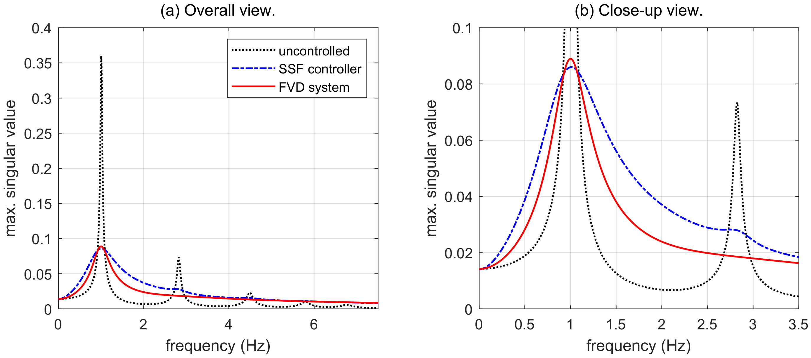
The frequency response produced by the designed FVD system is displayed in Figure 4, where the red solid line corresponds to the closed-loop FRF defined by the diagonal SVF gain-matrix K ( 6 ) , the blue dash-dotted line represents the closed-loop FRF associated to the optimal SSF gain-matrix G ^ and the black dotted line appertains to the open-loop FRF
T o ( ω ) = C z 2 π ω j I n x A 1 E ,
which describes the frequency response of the uncontrolled building. The overall view in Figure 4a shows the building resonant peaks, which are located at the natural frequencies given in Table 1. The magnitude of the main resonant peak is
γ o = 0.3619
and corresponds to the H -norm of the uncontrolled building. Looking at the plots in that figure, it can be appreciated that the proposed FVD system produces a remarkable reduction of the main resonant peak and, quite surprisingly, a slightly better overall response than the optimal SSF controller. The frequency response of the FVD system and the SSF active controller can be more effectively compared from the close-up view in Figure 4b, where it can be observed that the FVD system produces a uniformly smaller frequency-response with the exception of a tiny interval around the main resonant frequency, which is consistent with the γ -values in Equations (72) and (74) and the H optimality of the SSF controller.

4.2. Seismic Response

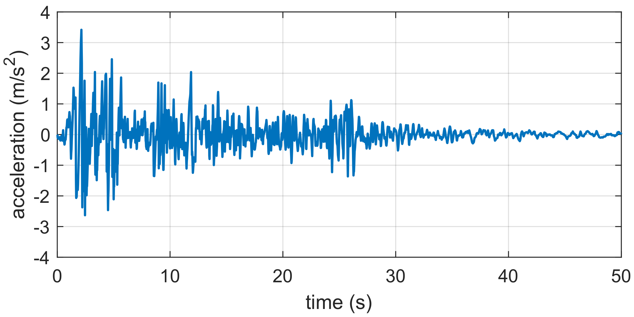
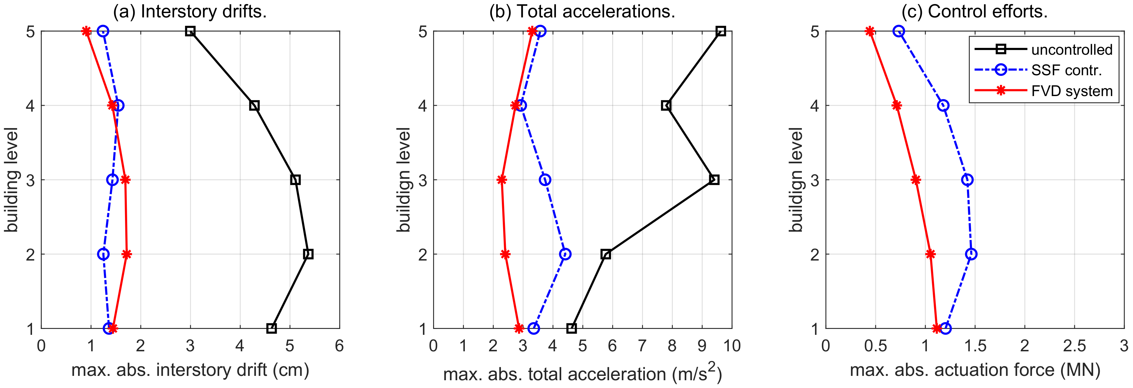
To illustrate the seismic performance of the designed FVD system, we have computed the interstory-drift, total-acceleration and actuation-force time responses produced by the full-scale 180-component of the El Centro 1940 ground-acceleration seismic record displayed in Figure 5. As a natural reference, we have also computed the time responses corresponding to the uncontrolled building and the optimal SSF H controller. The obtained absolute peak-values
| r i | max = max 0 t 50 | r i ( t ) | , | a i | max = max 0 t 50 | a i ( t ) | , | u i | max = max 0 t 50 | u i ( t ) | , i = 1 , , 5
are displayed in Figure 6, where the red solid lines with asterisks correspond to the FVD system with the damping coefficients in Table 3, the blue dash-dotted lines with circles represent the optimal SSF controller with the control gain matrix G ^ in Equation (73), and the black solid lines with squares describe the uncontrolled building response. Looking at the plots in Figure 6a, it can be appreciated that the proposed FVD system produces remarkable reductions of the interstory-drift peak-values, which according to the values in Table 4, are superior to 66% in all the building levels. The plots in Figure 6b and the data in Table 5 indicate that the FVD system also produces significant reductions of the total-acceleration peak-values, which are about a 38% at the building bottom level and superior to 64% in the upper levels.
When compared with the optimal SSF controller, the obtained time-domain results come to confirm the high-performance characteristics of the FVD system pointed out by the frequency-domain responses discussed in Section 4.1. Specifically, despite assuming an ideal active implementation with full-state feedback information, the optimal SSF controller is only able to produce appreciable improved results in the interstory-drift peak-values | r 2 | max and | r 3 | max . For the rest of considered peak-values, including the actuation-force peak-values displayed in Figure 6c, the results achieved by the passive FVD system are similar or superior to those attained by the optimal SSF controller.
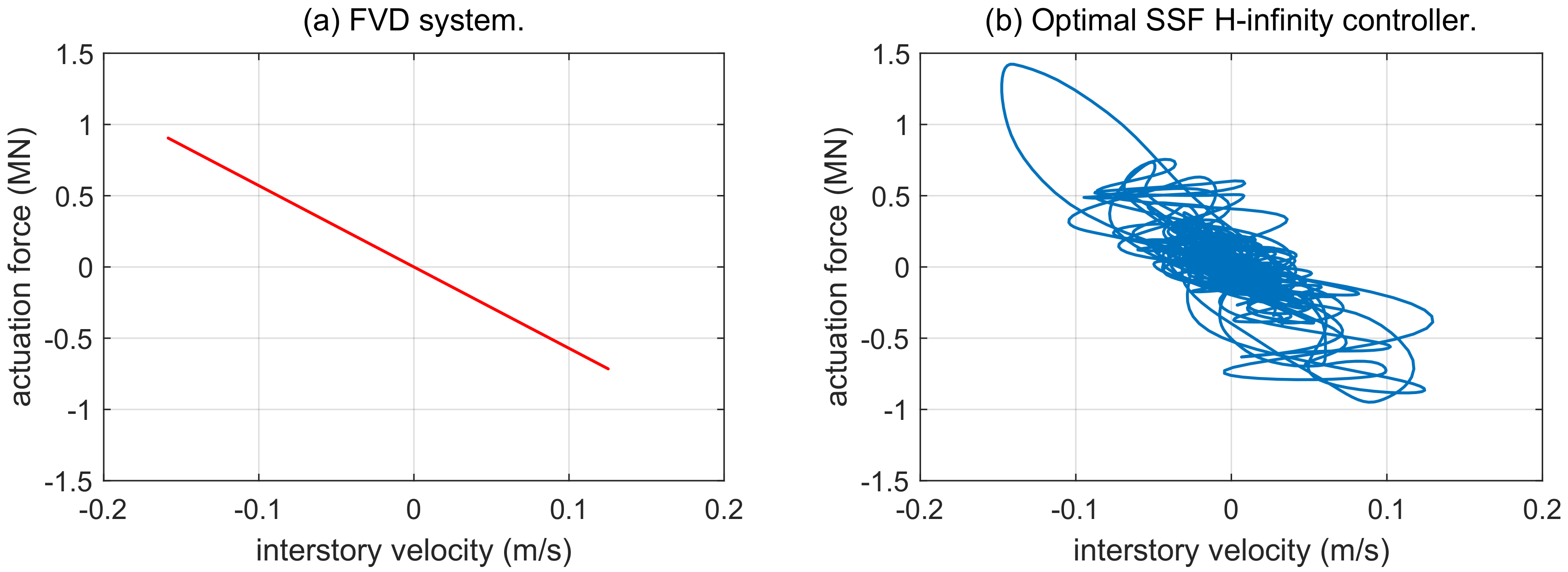
To complement the peak-value information and provide a clearer view of the time-domain responses, the interstory-drift, total-acceleration and actuation-force time histories corresponding to the 3rd building-level are displayed in Figure 7, Figure 8 and Figure 9, respectively. To facilitate the comparison, Figure 7 and Figure 8 present a close-up view of the FVD and SSF responses, and display in the background the clipped response of the uncontrolled building, which for the 3rd building-level has an interstory-drift peak-value of 5.11 cm and a total-acceleration peak-value of 9.41 m/s 2 (see Figure 6a,b). Moreover, the corresponding plots of actuation forces versus interstory drifts and interstory velocities are respectively presented in Figure 10 and Figure 11.
The interstory-drift plots in Figure 7a,b are quite similar, with slightly larger peaks in the FVD system response, which are consistent with the percentages of peak-value reduction presented in Table 4. The total-acceleration plots in Figure 8a,b indicate an overall better performance of the FVD system, with an appreciable reduced response in several time subintervals. For example, around t = 2 s, t = 10 s and t = 25 s. Finally, the plots in Figure 9 and Figure 10 demonstrate the larger actuation-force values required by the SSF controller, and the plot in Figure 11a clearly evidences the passive character of the designed ISSD system.
Remark 3.
The interstory FVD system discussed in this paper has been designed following an H controller design approach. However, it should be observed that the proposed design methodology can be extended to other advanced controller design strategies that admit a BMI formulation.
Remark 4.
All the computations have been carried out with Matlab 2020a on a regular desktop computer equipped with an Intel Core i7-8700 CPU at 3.20 GHz, 16 GB RAM and a 480 GB SSD hard drive. The optimization LMI problems have been solved with the function mincx() of the Matlab Robust Control Toolbox [45], setting a relative tolerance of 10 5 .

5. Conclusions

In this work, we have introduced a novel iterative linear matrix inequality (ILMI) procedure, which can be applied to compute enhanced suboptimal solutions for optimization problems with structured bilinear matrix inequality (BMI) constraints. After discussing the connections between passive damping systems and decentralized static velocity-feedback (SVF) controllers, the design of fluid viscous damper (FVD) systems has been set as a decentralized SVF H controller-design problem, which admits a BMI formulation and can be solved with the proposed ILMI procedure. The main features of the presented methodology have been demonstrated by designing a system of supplemental interstory FVDs to mitigate the seismic response of a five-story building model. In the performance assessment of the obtained passive damping system, we have studied the frequency-domain and time-domain responses, taking as reference the optimal static state-feedback H controller. Considering the results achieved in this paper, the following points can be highlighted: (i) Active controller-design strategies can be applied to design FVD systems with high-performance characteristics. (ii) The followed H controller-design approach does not depend on particular seismic records. (iii) For the considered problem, the proposed ILMI procedure can be initialized by solving a simple matrix Lyapunov equation. (iv) The study of the frequency response functions indicates that the obtained FVD system produces a relevant reduction of the main and secondary resonant peaks. (v) The study of the time-history responses indicates that the obtained FVD system produces a significant and well-balanced reduction of the interstory-drift and absolute-acceleration peak values in all the building levels. (vi) The performance characteristics of the obtained FVD system are similar, and sometimes superior, to those attained by the optimal H state-feedback active controller.
Natural extensions of this work are the study of computational effectiveness in large structural problems and the design of ISSD systems with mixed interstory-interbuilding damping links for seismic protection of adjacent buildings. Additional research lines associated to the application of the proposed ILMI procedure to other problems of practical interest include the design of high-performance automotive suspensions [46] and the combination of health monitoring techniques with ISSD system design to define scalable and adaptive retrofitting schemes [47,48].

Author Contributions

Conceptualization, formal analysis, investigation, methodology and writing—review & editing were conducted collaboratively by all the authors; software, F.P.-Q. and J.R.-M.; visualization, J.R.-M. and J.M.R.; writing—original draft, F.P.-Q., J.R.-M. and H.R.K. All authors have read and agreed to the published version of the manuscript.

Funding

This research was partially supported by the Spanish Ministry of Economy and Competitiveness under Grant DPI2015-64170-R/FEDER and by the Italian Ministry of Education, University and Research under the Project “Department of Excellence LIS4.0—Lightweight and Smart Structures for Industry 4.0”.

Conflicts of Interest

The authors declare no conflict of interest.

Abbreviations

The following abbreviations are used in this manuscript:
BIbase isolation
BMIbilinear matrix inequality
BRLbounded real lemma
FRFfrequency response function
FVDfluid viscous damper
ILMIiterative linear matrix inequality
ISSDinter-substructure damper
LMIlinear matrix inequaltiy
SOFstatic output feedback
SSFstatic state feedback
SVFstatic velocity feedback
TDtuned damper
TMDtuned mass damper

References

  1. Soong, T.T.; Spencer, B.F., Jr. Supplemental energy dissipation: State-of-the-art and state-of-the-practice. Eng. Struct. 2002, 24, 243–259. [Google Scholar] [CrossRef]
  2. Symans, M.D.; Charney, F.A.; Whittaker, A.S.; Constantinou, M.C.; Kircher, C.A.; Johnson, M.W.; McNamara, R.J. Energy dissipation systems for seismic applications: Current practice and recent developments. J. Struct. Eng. 2008, 134, 3–21. [Google Scholar] [CrossRef] [Green Version]
  3. Takewaki, I.; Fujita, K.; Yamamoto, K.; Takabatake, H. Smart passive damper control for greater building earthquake resilience in sustainable cities. Sustain. Cities Soc. 2011, 1, 3–15. [Google Scholar] [CrossRef] [Green Version]
  4. Ho, C.; Zhu, Y.; Lang, Z.Q.; Billings, S.A.; Kohiyama, M.; Wakayama, S. Nonlinear damping based semi-active building isolation system. J. Sound Vib. 2018, 424, 302–317. [Google Scholar] [CrossRef]
  5. De Domenico, D.; Impollonia, N.; Ricciardi, G. Soil-dependent optimum design of a new passive vibration control system combining seismic base isolation with tuned inerter damper. Soil Dyn. Earthq. Eng. 2018, 105, 37–53. [Google Scholar] [CrossRef]
  6. Peng, Y.; Ding, L.; Chen, J. Performance evaluation of base-isolated structures with sliding hydromagnetic bearings. Struct. Control Health Monit. 2019, 26, 1–21. [Google Scholar] [CrossRef] [Green Version]
  7. De Domenico, D.; Gandelli, E.; Quaglini, V. Adaptive isolation system combining low-friction sliding pendulum bearings and SMA-based gap dampers. Eng. Struct. 2020, 212, 1–25. [Google Scholar] [CrossRef]
  8. Elias, S.; Matsagar, V. Research developments in vibration control of structures using passive tuned mass dampers. Annu. Rev. Control 2017, 44, 129–156. [Google Scholar] [CrossRef]
  9. Love, J.S.; McNamara, K.P.; Tait, M.J.; Haskett, T.C. Series-type pendulum tuned mass damper-tuned sloshing damper. J. Vib. Acoust. 2020, 142, 1–8. [Google Scholar] [CrossRef]
  10. Pandey, D.K.; Sharma, M.K.; Mishra, S.K. A compliant tuned liquid damper for controlling seismic vibration of short period structures. Mech. Syst. Signal Process. 2019, 132, 405–428. [Google Scholar] [CrossRef]
  11. Lu, Z.; Li, K.; Ouyang, Y.; Shan, J. Performance-based optimal design of tuned impact damper for seismically excited nonlinear building. Eng. Struct. 2018, 160, 314–327. [Google Scholar] [CrossRef]
  12. Bathaei, A.; Zahrai, S.M.; Ramezani, M. Semi-active seismic control of an 11-DOF building model with TMD+MR damper using type-1 and -2 fuzzy algorithms. J. Vib. Control 2018, 24, 2938–2953. [Google Scholar] [CrossRef]
  13. Shih, M.H.; Sung, W.P. Structural control effect and performance of structure under control of impulse semi-active mass control mechanism. Iran. J. Sci. Technol. Trans. Civ. Eng. 2020. [Google Scholar] [CrossRef]
  14. De Domenico, D.; Ricciardi, G. Earthquake-resilient design of base isolated buildings with TMD at basement: Application to a case study. Soil Dyn. Earthq. Eng. 2018, 113, 503–521. [Google Scholar] [CrossRef]
  15. Li, Z.; Shu, G.; Huang, Z. Proper configuration of metallic energy dissipation system in shear-type building structures subject to seismic excitation. J. Constr. Steel Res. 2019, 154, 177–189. [Google Scholar] [CrossRef]
  16. Atam, E. Friction damper-based passive vibration control assessment for seismically-excited buildings through comparison with active control: A case study. IEEE Access 2019, 7, 4664–4675. [Google Scholar] [CrossRef]
  17. Tchamo, J.M.; Zhou, Y. An alternative practical design method for structures with viscoelastic dampers. Earthq. Eng. Eng. Vib. 2018, 17, 459–473. [Google Scholar] [CrossRef]
  18. De Domenico, D.; Ricciardi, G.; Takewaki, I. Design strategies of viscous dampers for seismic protection of building structures: A review. Soil Dyn. Earthq. Eng. 2019, 118, 144–165. [Google Scholar] [CrossRef]
  19. Palacios-Quiñonero, F.; Rubió-Massegú, J.; Rossell, J.M.; Karimi, H.R. Design of inerter-based multi-actuator systems for vibration control of adjacent structures. J. Frankl. Inst. 2019, 356, 7785–7809. [Google Scholar] [CrossRef]
  20. Palacios-Quiñonero, F.; Rubió-Massegú, J.; Rossell, J.M.; Karimi, H.R. Integrated design of hybrid interstory-interbuilding multi-actuation schemes for vibration control of adjacent buildings under seismic excitations. Appl. Sci. 2017, 7, 323. [Google Scholar] [CrossRef] [Green Version]
  21. Apostolakis, G. Optimal evolutionary seismic design of three-dimensional multistory structures with damping devices. J. Struct. Eng. 2020, 146, 1–16. [Google Scholar] [CrossRef]
  22. De Domenico, D.; Ricciardi, G. Earthquake protection of structures with nonlinear viscous dampers optimized through an energy-based stochastic approach. Eng. Struct. 2019, 179, 523–539. [Google Scholar] [CrossRef]
  23. Del Gobbo, G.M.; Williams, M.S.; Blakeborough, A. Comparing fluid viscous damper placement methods considering total-building seismic performance. Earthq. Eng. Struct. Dyn. 2018, 47, 2864–2886. [Google Scholar] [CrossRef]
  24. Li, Z.; Shu, G. Optimal placement of metallic dampers for seismic upgrading of multistory buildings based on a cost-effectiveness criterion using genetic algorithm. Struct. Des. Tall Spec. Build. 2019, 28, 1–18. [Google Scholar] [CrossRef]
  25. Altieri, D.; Tubaldi, E.; De Angelis, M.; Patelli, E.; Dall’Asta, A. Reliability-based optimal design of nonlinear viscous dampers for the seismic protection of structural systems. Bull. Earthq. Eng. 2018, 16, 963–982. [Google Scholar] [CrossRef] [Green Version]
  26. Sarcheshmehpour, M.; Estekanchi, H.E.; Ghannad, M.A. Optimum placement of supplementary viscous dampers for seismic rehabilitation of steel frames considering soil–structure interaction. Struct. Des. Tall Spec. Build. 2019, 29, 1–17. [Google Scholar] [CrossRef]
  27. Palacios-Quiñonero, F.; Rubió-Massegú, J.; Rossell, J.M.; Karimi, H.R. Distributed passive actuation schemes for seismic protection of multibuilding systems. Appl. Sci. 2020, 10, 2383. [Google Scholar] [CrossRef] [Green Version]
  28. De Domenico, D.; Qiao, H.; Wang, Q.; Zhu, Z.; Marano, G. Optimal design and seismic performance of Multi-Tuned Mass Damper Inerter (MTMDI) applied to adjacent high-rise buildings. Struct. Des. Tall Spec. Build. 2020. [Google Scholar] [CrossRef]
  29. Nabid, N.; Hajirasouliha, I.; Petkovski, M. Adaptive low computational cost optimisation method for performance-based seismic design of friction dampers. Eng. Struct. 2019, 198, 1–12. [Google Scholar] [CrossRef]
  30. Halperin, I.; Ribakov, Y.; Agranovich, G. Optimal viscous dampers gains for structures subjected to earthquakes. Struct. Control Health Monit. 2016, 23, 458–469. [Google Scholar] [CrossRef]
  31. Palacios-Quiñonero, F.; Rubió-Massegú, J.; Rossell, J.M.; Rodellar, J. Interstory-interbuilding actuation schemes for seismic protection of adjacent identical buildings. Smart Struct. Syst. 2019, 24, 67–81. [Google Scholar] [CrossRef]
  32. Akehashi, H.; Takewaki, I. Optimal viscous damper placement for elastic-plastic MDOF structures under critical double impulse. Front. Built Environ. 2019, 5, 1–17. [Google Scholar] [CrossRef] [Green Version]
  33. Pollini, N.; Lavan, O.; Amir, O. Towards realistic minimum-cost optimization of viscous fluid dampers for seismic retrofitting. Bull. Earthq. Eng. 2016, 14, 971–998. [Google Scholar] [CrossRef]
  34. Palermo, M.; Silvestri, S.; Landi, L.; Gasparini, G.; Trombetti, T. A direct five-step procedure for the preliminary seismic design of buildings with added viscous dampers. Eng. Struct. 2018, 173, 933–950. [Google Scholar] [CrossRef]
  35. Palacios-Quiñonero, F.; Rubio-Massegu, J.; Rossell, J.M.; Karimi, H.R. Optimal passive-damping design using a decentralized velocity-feedback H approach. Model. Identif. Control 2012, 33, 87–97. [Google Scholar] [CrossRef] [Green Version]
  36. Rubió-Massegú, J.; Rossell, J.M.; Karimi, H.R.; Palacios-Quiñonero, F. Static output-feedback control under information structure constraints. Automatica 2013, 49, 313–316. [Google Scholar] [CrossRef] [Green Version]
  37. Rubió-Massegú, J.; Palacios-Quiñonero, F.; Rossell, J.M. Decentralized static output-feedback H controller design for buildings under seismic excitation. Earthq. Eng. Struct. Dyn. 2012, 41, 1199–1205. [Google Scholar] [CrossRef]
  38. Palacios-Quiñonero, F.; Rubió-Massegú, J.; Rossell, J.M.; Karimi, H.R. Feasibility issues in static output-feedback controller design with application to structural vibration control. J. Frankl. Inst. 2014, 351, 139–155. [Google Scholar] [CrossRef] [Green Version]
  39. Chopra, A.K.; McKenna, F. Modeling viscous damping in nonlinear response history analysis of buildings for earthquake excitation. Earthq. Eng. Struct. Dyn. 2016, 45, 193–211. [Google Scholar] [CrossRef]
  40. Boyd, S.; Ghaoui, L.E.; Feron, E.; Balakrishnan, V. Linear Matrix Inequalities in System and Control Theory; SIAM Studies in Applied Mathematics; Society for Industrial and Applied Mathematics: Philadelphia, PA, USA, 1994. [Google Scholar]
  41. Huo, L.; Qu, C.; Li, H. TLCD parametric optimization for the vibration control of building structures based on linear matrix inequality. J. Appl. Math. 2014, 2014, 1–10. [Google Scholar] [CrossRef] [Green Version]
  42. Liu, Z.Y.; Wu, H.N. New insight into the simultaneous policy update algorithms related to H state feedback control. Inf. Sci. 2019, 484, 84–94. [Google Scholar] [CrossRef]
  43. Kurata, N.; Kobori, T.; Takahashi, M.; Niwa, N.; Midorikawa, H. Actual seismic response controlled building with semi-active damper system. Earthq. Eng. Struct. Dyn. 1999, 28, 1427–1447. [Google Scholar] [CrossRef]
  44. Chopra, A.K. Dynamics of Structures. Theory and Applications to Earthquake Engineering, 3rd ed.; Prentice Hall: Upper Saddle River, NJ, USA, 2007. [Google Scholar]
  45. Balas, G.J.; Chiang, R.Y.; Packard, A.K.; Safonov, M.G. MATLAB Robust Control Toolbox User’s Guide, 2020a; The MathWorks, Inc.: Natick, MA, USA, 2020. [Google Scholar]
  46. Rubió-Massegú, J.; Rossell, J.M.; Palacios-Quiñonero, F.; Karimi, H.R. Static output-feedback controller design for vehicle suspensions: An effective two-step computational approach. IET Control Theory Appl. 2014, 8, 1566–1574. [Google Scholar] [CrossRef] [Green Version]
  47. Konstantinidis, D.; Makris, N.; Kelly, J.M. Health monitoring of fluid dampers for vibration control of structures: Experimental investigation. Earthq. Eng. Struct. Dyn. 2012, 41, 1813–1829. [Google Scholar] [CrossRef]
  48. Maizuar, M.; Zhang, L.; Miramini, S.; Mendis, P.; Thompson, R.G. Detecting structural damage to bridge girders using radar interferometry and computational modelling. Struct. Control Health Monit. 2017, 24, 1–6. [Google Scholar] [CrossRef]
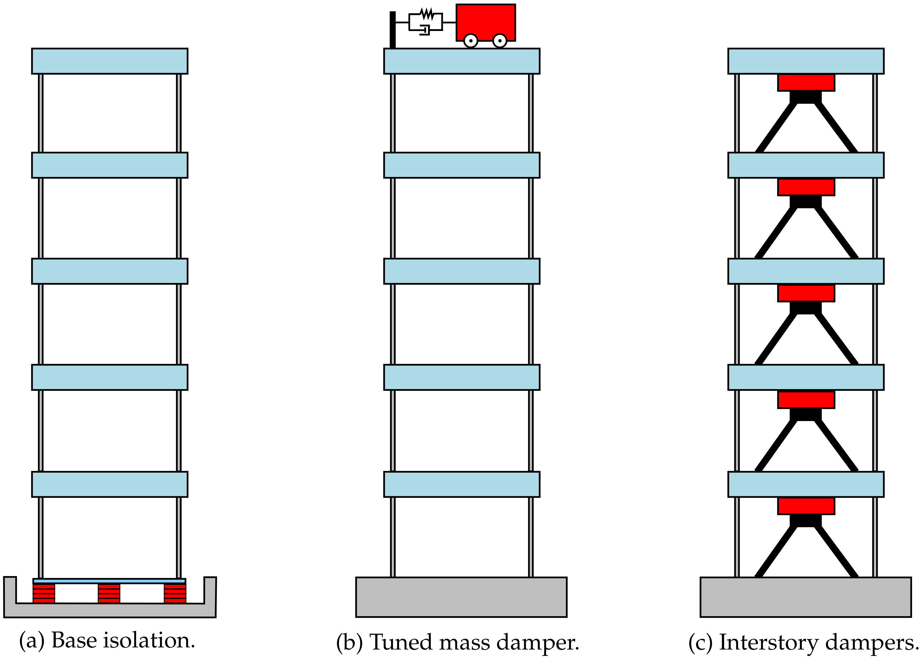
Figure 1. Passive vibration control strategies for seismic protection of multistory buildings.
Applsci 10 05859 g001
Figure 2. Schematic model of a multistory building equipped with a complete set of interstory fluid viscous dampers.
Applsci 10 05859 g002
Figure 3. Multistory building equipped with a complete set of ideal interstory force-actuation devices and collocated interstory-velocity sensors.
Applsci 10 05859 g003
Figure 4. Maximum singular values of the FRFs corresponding to the uncontrolled building (black dotted line), the optimal SSF controller (blue dash-dotted line) and the computed FVD system (red solid line). (a) Overall view. (b) Close-up view of the main resonant peaks.
Applsci 10 05859 g004
Figure 5. El Centro 1940 ground-acceleration seismic record, full-scale 180-component with an absolute acceleration-peak of 3.417 m/s 2 .
Applsci 10 05859 g005
Figure 6. Time-response peak-values. (a) Maximum absolute interstory drifts ( × 10 2 m). (b) Maximum absolute total accelerations (m/s 2 ). (c) Maximum absolute actuation forces ( × 10 6 N).
Applsci 10 05859 g006
Figure 7. Close-up view of the interstory-drift time-response r 3 ( t ) for the FVD system and the optimal SSF H controller. The black dotted line in the background represents the clipped response of the uncontrolled building.
Applsci 10 05859 g007
Figure 8. Close-up view of the total-acceleration time-response a 3 ( t ) for the FVD system and the optimal SSF H controller. The black dotted line in the background represents the clipped response of the uncontrolled building.
Applsci 10 05859 g008
Figure 9. Actuation-force time-history u 3 ( t ) for the FVD system and the optimal SSF H controller.
Applsci 10 05859 g009
Figure 10. Plots of actuation force versus interstory drift in the 3rd story level corresponding to the FVD system and the optimal SSF H controller.
Applsci 10 05859 g010
Figure 11. Plots of actuation force versus interstory velocity in the 3rd story level corresponding to the FVD system and the optimal SSF H controller.
Applsci 10 05859 g011
Table 1. Natural frequencies of the five-story building model.
Mode12345
natural frequency (Hz)1.0082.8254.4935.7976.773
Table 2. Values of the upper bounds η i 1 / 2 obtained in the steps i = 0 , , 6 .
Step0123456
Upper bound η i 1 / 2 0.09330.09110.09020.09000.08990.08980.0898
Table 3. Damping coefficients of the interstory FVD system.
Building Level12345
Damping coefficient c ^ i ( × 10 6 Ns/m)8.41446.65705.70925.17994.9493
Table 4. Interstory-drift peak-value reductions with respect to the uncontrolled response.
Building Level12345
FVD system68.8968.0166.9366.6569.81
SSF controller70.5876.7672.0063.8958.61
Table 5. Total-acceleration peak-value reductions with respect to the uncontrolled response.
Building Level12345
FVD system38.0958.3275.7064.7865.65
SSF controller27.4323.4860.2862.5462.85