Article

Experimental Evaluation on the Effect of Electrode Configuration in Electrostatic Actuators for Increasing Vibrotactile Feedback Intensity

1
Department of Mechanical and Manufacturing Engineering, Miami University, Oxford, OH 45056, USA
2
Future Medicine Division, Korea Institute of Oriental Medicine, 1672, Yuseong-daero, Yuseong-gu, Daejeon 34054, Korea
3
Department of Electronic Engineering, Korea National University of Transportation, 50, Daehak-ro, Chungju-si 27469, Korea
*
Author to whom correspondence should be addressed.
Appl. Sci. 2020, 10(15), 5375; https://doi.org/10.3390/app10155375
Submission received: 14 July 2020 / Revised: 29 July 2020 / Accepted: 31 July 2020 / Published: 4 August 2020
(This article belongs to the Special Issue Haptics: Technology and Applications)

Abstract

:
Vibrotactile feedback is a key feature of many modern touch displays, which greatly enhances user experiences when interacting with an onscreen interface. Despite its popularity in small touch screen devices, this haptic feature is absent in most large displays due to a lack of suitable actuators for such applications. Thus, a growing need exists for haptic actuators capable of producing sufficient vibrations in large touch displays. This study proposes and evaluates a novel electrostatic resonant actuator (ERA) with a moving mass and dual electrodes for increased vibration feedback intensity. The dual-electrode ERA was fabricated along with a comparable single-electrode ERA to investigate the effect of the electrode configuration on the maximum vibration intensity. When measured directly on the mass, the maximum vibration intensity of the dual-electrode actuator increased by 73% compared to the single-electrode actuator. When mounted and measured on a mock panel, the maximum vibration intensity of the dual-electrode actuator increased by nearly 65% compared to a similarly mounted single-electrode actuator. These results show that the dual-electrode configuration can significantly increase the vibration intensity when compared to the conventional ERA. This demonstrates a promising potential for the use of the proposed actuator for generating vibrotactile feedback in large touch displays.

1. Introduction

Touchscreens have become increasingly popular in everyday electronics. This electronic visual display technology provides an enhanced user experience different than that of traditional input methods, such as a keyboard and mouse. In many applications, touchscreens are quicker and easier to use because of their direct finger to screen input method, which can help make computing resources more accessible to people who struggle with typical input methods [1]. Moreover, by combining touchscreens with on-screen images, the operation becomes intuitive, significantly increasing operability and usefulness [2]. Vibration sensations felt on the surface of a touchscreen, known as vibrotactile haptic feedback, are commonly used in small consumer electronics to create engaging user interfaces without the need for mechanical buttons [3]. Studies have shown that the implementation of such haptic modules in touch displays increases input speed and input accuracy, as well as user feedback and satisfaction [4,5,6]. Touchscreen modules can create a wide variety of vibrotactile sensations for users for many different applications. Coupled with visual feedback, they can provide a significantly improved user experience and help convey visual information to the visually impaired [2,7]. The benefits of haptic displays and devices are immense, making them highly sought after in many types of touch displays.
As the popularity of touchscreens continues to increase, the industry strives to incorporate touch interfaces in large displays to improve its functionality and versatility. Currently, large touchscreens are being considered in a multitude of applications such as large tablets, interactive kiosk systems, and automobile center control stacks [8]. Many small touchscreen electronics utilize vibrotactile feedback; however, this feedback is lacking in the developing market for large touch displays. This is because most of the current haptic actuators used in touch displays are small and lightweight, allowing them to fit in mobile devices, but they fail to create sufficiently large vibrational sensations when used in bigger screens. Devices with large touchscreens (10-inch or larger) typically lack the capability of generating vibrotactile feedback for the users despite the many benefits offered by haptic feedback. For example, properly implementing vibrotactile feedback into the automotive center control stack would greatly improve functionality, user feedback, and safety [5]. There exists a growing need for developing new haptic actuators capable of generating sufficient vibrotactile feedback sensations in large touchscreens.
There are currently very few haptic actuators that can produce meaningful tactile feedback for large touchscreen displays. The most important factors that make an actuator viable for large screen applications are high vibration intensity, low response time, low residual vibrations, and geometry. A study by Kaaresoja et al. showed that tactile feedback latency, or response time, did not create a significant effect on typing speed or accuracy, but did largely diminish the user’s perceived pleasantness. This makes response time still an important factor to consider when implementing haptic feedback [9]. Some of the current actuators used for haptic feedback include eccentric rotary motor (ERM) actuators, linear resonant actuators (LRAs), piezoelectric actuators, and electrostatic actuators. Each of these commonly used actuators have many benefits but their drawbacks can make them difficult to effectively implement into large displays.
ERM actuators are the most widely used actuator for mobile devices and other simple vibration cases. This device utilizes an unbalanced mass that uses rotation to generate vibrations for the users. The ERM actuator vibration intensity is linked to the input frequency, making it not very versatile. It also has long response times (more than 100 ms) and residual vibrations from the inertia of the mass [10]. ERM actuators also produce relatively weak vibrations due to the small size of the mass. Increasing the size of the mass would increase the vibration strength but would also accentuate the actuator’s weaknesses, making it not a feasible option for vibrotactile haptic use [11].
Linear resonant actuators (LRA) use an electromagnet and spring mechanism to provide vibrotactile sensations. These devices are small and have a faster startup time (about 20 ms) compared to the ERM actuator, but they also produce a lot of residual vibrations and are limited in to use at their resonant frequency [10,11]. These actuators also cannot create sufficiently large vibration forces for large touchscreen applications. A specialized linear impact resonant actuator was developed by Pyo et al. that could be used at a wide range of frequencies with low power consumption, but it could only generate a maximum of 3 g-forces at the resonant frequency [10]. This could be applied to mobile touchscreen applications but is still not sufficient for use in larger screens. Increasing the size of an LRA would increase the response time and greatly increase power consumption, limiting its use in large touchscreen applications [11].
Piezoelectric or piezo actuators can create a wide variety of precise tactile sensations due to their short startup time (as little as 5 ms) and their possibility to create short-duration vibrations (under 3 milliseconds) [10]. They also operate at a wide range of frequencies, altogether creating high-fidelity sensations. Piezo actuators can create almost any kind of one-dimensional haptic sensation with a relatively large dynamical range. However, they also create a potentially unwanted sound when actuating, whose frequency and volume depend on the material, environmental, and driving factors [12]. Piezo actuators are very thin, which can be ideal for use in electronic devices but also makes them very fragile. Although piezo actuators could be attached to touchscreen panels to cause direct vibration, this is not desirable because of reliability and durability issues [11]. These actuators being expensive and requiring a lot of operation power, along with the previously mentioned disadvantages, make them not ideal for large touchscreen applications.
Electrostatic actuators rely on electrostatic attraction forces to create haptic sensations. Typically, parallel plate actuation is employed in electrostatic actuators where one electrode is fixed and another is moveable via a spring, causing oscillations. The electrostatic attraction force directly depends on the electrode area, making it easy to scale up in size. Furthermore, the small distances involved can create large electrostatic fields. One important disadvantage of parallel plate actuators is the concept of snap-in. The spring restoring force is linear, while the electrostatic attraction force is not. This limits the displacement range of the electrode to about one-third of the original gap [13]. Electrostatic actuators are often used in haptic applications that benefit from a small and flat module, which could be as little as a few microns [14]. The easy scalability of the plates allows electrostatic actuators to be made specifically for large touchscreen applications. Frequency beating can be used in electrostatic actuators to simultaneously activate multiple mechanoreceptors on the skin which creates a multitude of unique sensations. An electrostatic beating actuator with no mechanical vibrotactile actuators was presented and characterized in a study by Joo et al. [15]. This study exemplifies one of the many ways electrostatic actuators can be utilized. However, these devices typically still cannot create sufficiently large vibration sensations when mounted onto a touchscreen. Recently, Koo et al. studied a new electrostatic actuator, or electrostatic resonant actuator (ERA), for large touchscreen applications. In their electrostatic actuator design, they used a single electrode with high voltage inputs and a moving mass in order to increase vibration intensity. By exploiting the beat phenomenon, created by two high voltage input signals that were applied to the electrode, they demonstrated the feasibility of the actuator for large display applications [11].
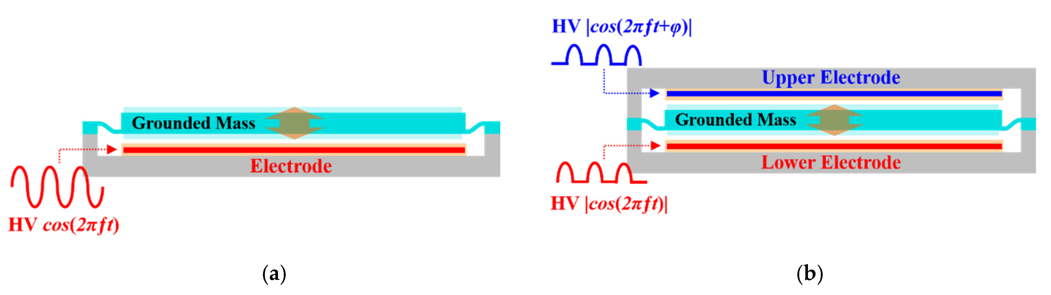
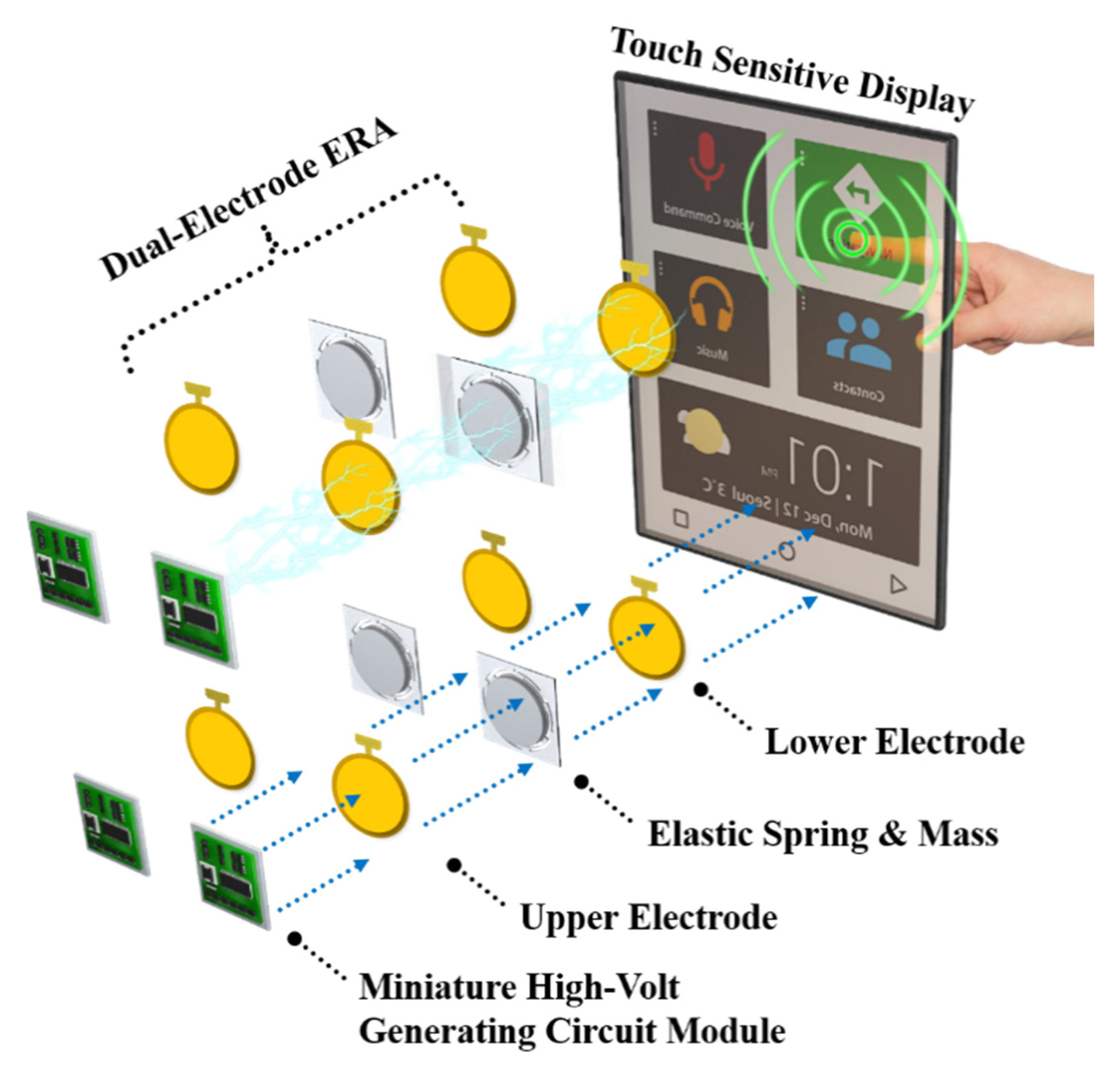
As an alternative to the single electrode ERA, this study proposes a new haptic module that incorporates two electrodes, referred to as the dual-electrode ERA design. In the proposed ERA, the additional electrode can increase the output vibration intensity when compared to that of a comparable ERA with a single electrode. 
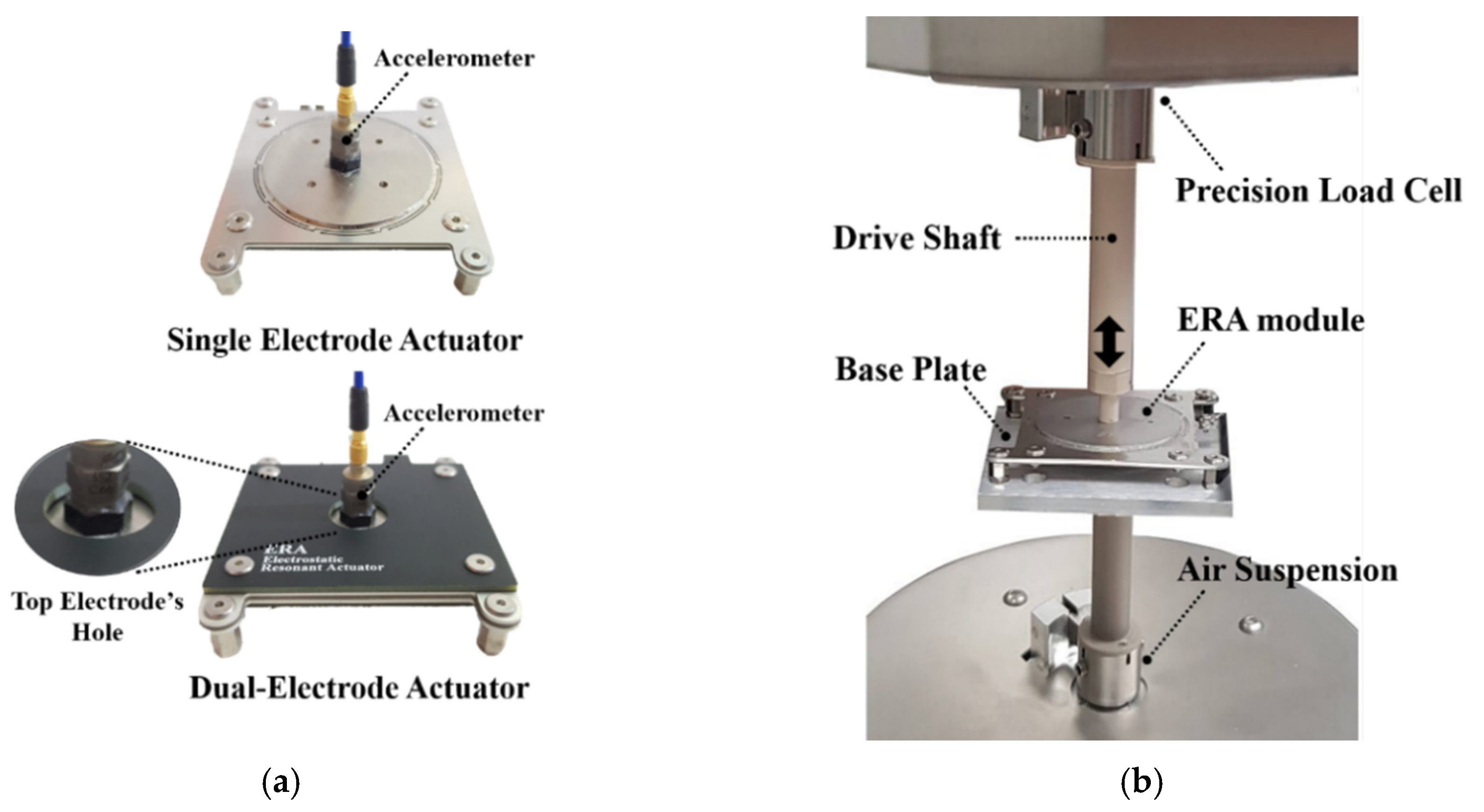
Figure 1 illustrates the electrode configurations for both electrostatic actuators. Figure 1a shows the single-electrode actuator geometry with an electrode below the mass, and 
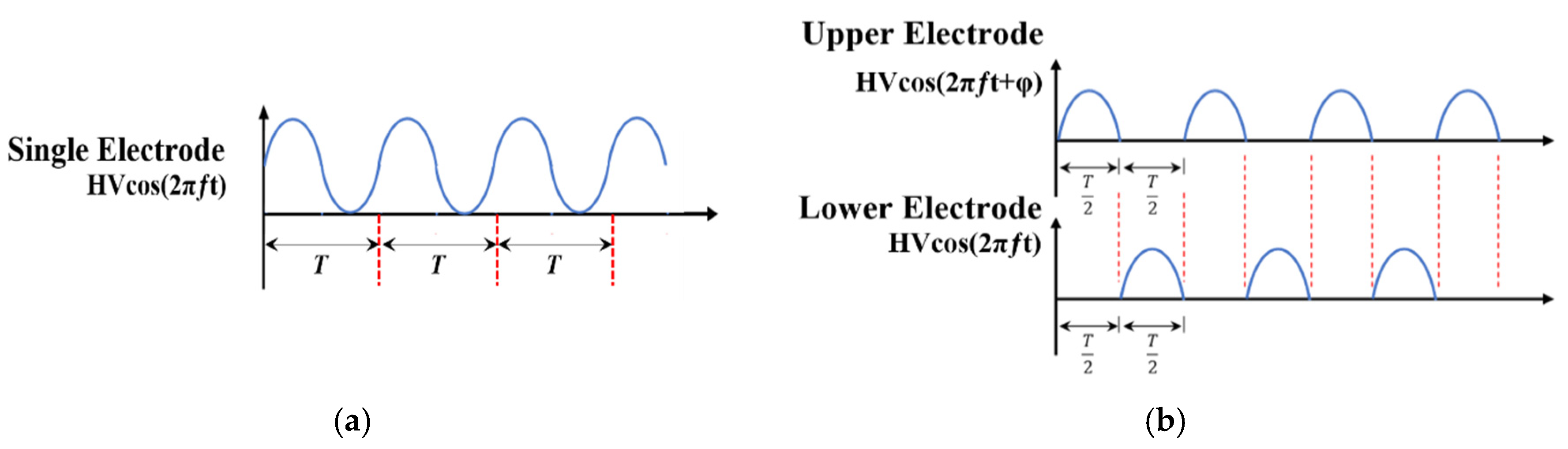
Figure 1b shows the dual-electrode actuator geometry with an electrode on each side of the mass. In the proposed two-electrode design, the electrodes are powered one at a time in an alternating fashion. This ensures that the forces generated by the upper and lower electrodes do not interfere. This was expected to significantly increase the vibration intensity of the actuator compared to using only a single electrode.
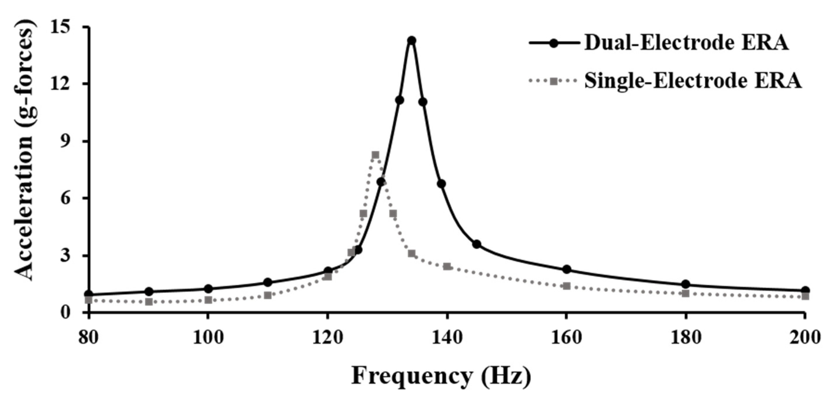
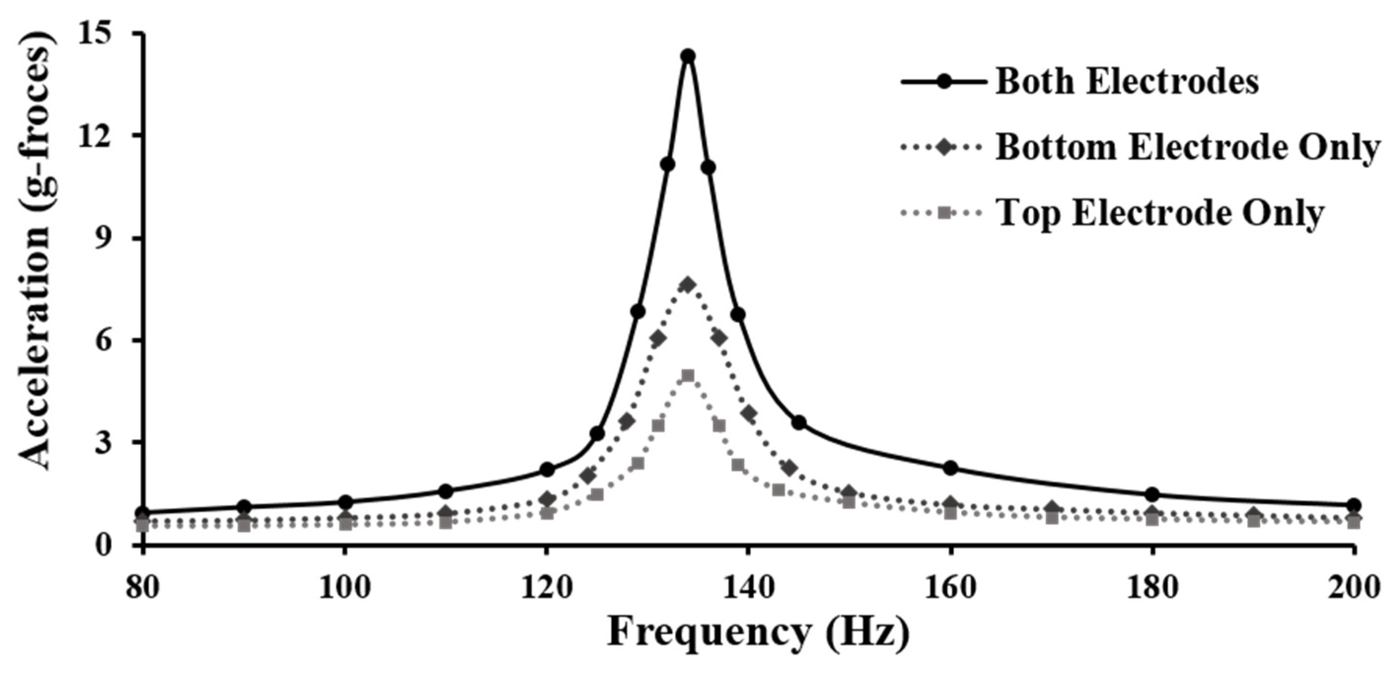
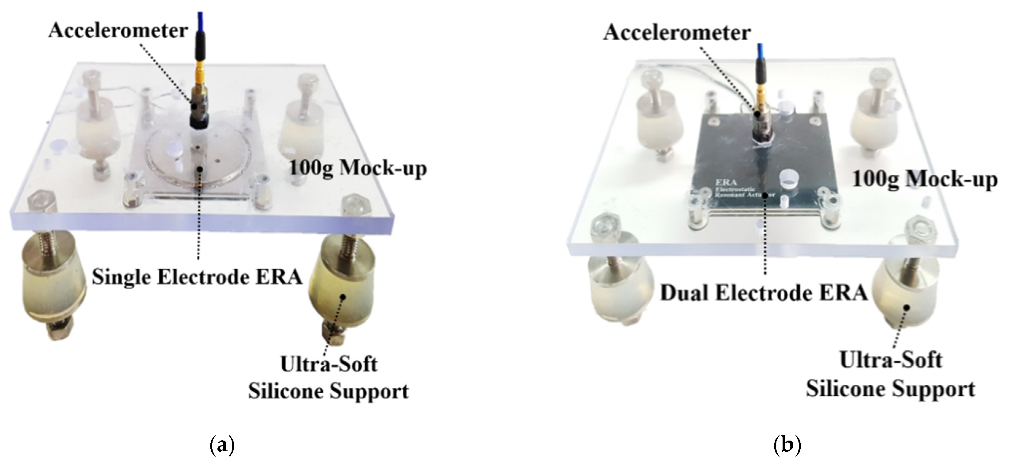
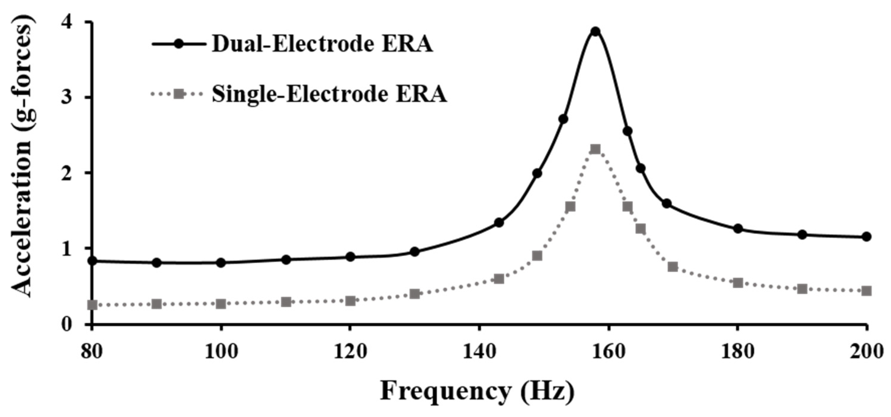
The primary goal of this study was to experimentally evaluate the effects of electrode configurations in increasing vibration intensity and to compare the performance of a single-electrode ERA to the proposed dual-electrode ERA. To this end, the dual-electrode actuator and custom controller were designed and fabricated along with a single-electrode ERA. Using the actuators, several tests were performed to identify and compare the actuators’ actual parameters to their design parameters. Following the actuation characterizations, the single-electrode and newly proposed dual-electrode actuators’ vibration performance was experimentally evaluated. Peak acceleration measurements were used to compare the performance of the actuators with both types of electrode configurations in producing vibration intensities.
The next section provides the working principle of the proposed dual-electrode actuator. After describing the construction of the actuators and the custom high voltage amplifiers in Section 3, the paper presents experimental results.

2. Proposed Dual-Electrode Actuator

This section offers descriptions of the working principle of the newly proposed dual-electrode electrostatic resonant actuator and the design overview. The main components of the proposed actuator module include the inertial, grounded mass in the center of the module, and, on either side of the mass, a spacer and an electrode. Figure 2 shows an exploded view and working principle design of the ERA module. Unlike traditional electrostatic actuators, it incorporates a moving mass, which is grounded electrically, in the module to increase vibration intensity. This mass is suspended between an upper and lower electrode through radial beam springs. A small air gap separates the mass and either electrode, allowing the mass to displace up and down when an electrostatic force is generated upon the application of high voltage inputs. When an electrode is charged with a high voltage input, a capacitance is created between the grounded mass and the electrode. Because the electrodes are fixed, the mass is pulled into the housing where the electrodes are attached. When the mass gets displaced, the radial beam springs create a restoring force that pulls it back towards the equilibrium position. This rapid change of forces causes the mass to oscillate, making the actuator vibrate.
The stainless-steel grounded mass in the module acts as a neutral conductive object while the electrodes act as electrically charged objects. When the electrodes are charged with a high voltage input, an electrical force attracts the mass to the electrodes. The equation for the electrostatic attraction force between the mass and a single (top or bottom) electrode is [16]:
F e ( t ) = ε r ε 0 A 2 ( V d a i r t D i e l e c t r i c ( 1 1 K e ) ) 2
where ε r is the relative permittivity of air, ε 0 is the vacuum permittivity, A is the area, V is the input voltage, d a i r is air gap distance, t D i e l e c t r i c is the thickness of the dielectric film, and K e is the relative permittivity of the dielectric film. The values for each parameter can be found in Table 1.

3. Prototype and Controller Fabrication

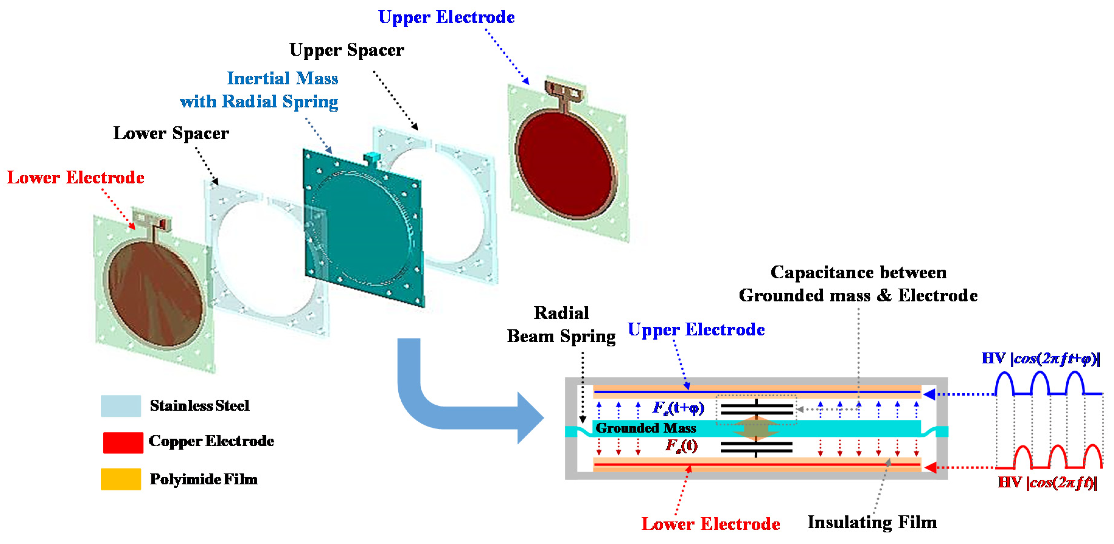
Two prototype actuators were fabricated to study the effect that electrode configuration has on the vibration intensity of the electrostatic resonant actuator module. Both actuators are proof-of-concept designs, made primarily to study the effect of adding an electrode above the mass. The dual-electrode ERA consists of five main parts: the lower electrode, the lower spacer, the inertial mass and spring, the upper spacer, and the upper electrode. Ten thin radial beam springs surround the center of the middle plate, creating a restoring force to the mass as it displaces away from its equilibrium position. This plate also has a protrusion that is used to wire the mass to electrical ground. A finite element method (FEM) simulation was performed to select the spring constant of the radial springs (see Figure 3a). A force of 2 N was applied to the mass, resulting in a maximum displacement of 0.1166 mm. Using the given size and mass constraints, the spring stiffness was selected to be 17.15 kN/m.
In 
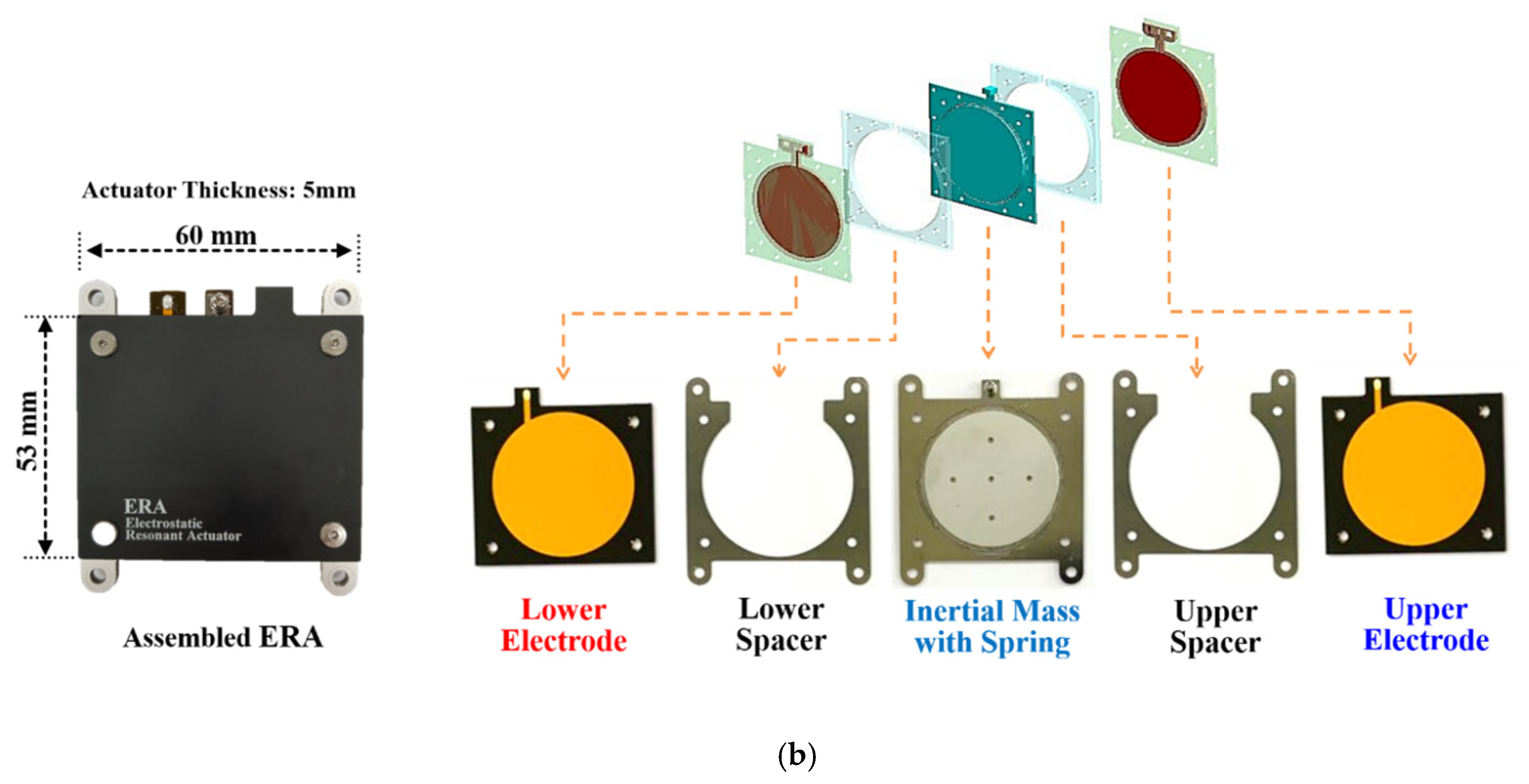
Figure 3b, each component of the actuator is separated, and its fabrication material is shown. The surface of each copper electrode closest to the mass is covered in a very thin layer of polyimide film to insulate them. The rest of the electrode is surrounded by a thicker layer of polyimide film to further insulate and support them. A stainless-steel spacer (thickness of 0.3 mm) is placed between each electrode and the mass at its equilibrium, creating an air gap, or rattle space, for the mass. The component containing the radial beam springs is a 0.5-mm-thick stainless steel plate. A stainless-steel cylinder was welded onto the center of the plate, providing significantly more mass, to increase vibration intensity. The complete assembled dual-electrode ERA is seen in the lower-left corner of Figure 3b. The single-electrode ERA was fabricated in the same manner but does not have a top electrode or spacer.
The values of key parameters for fabricating the ERA module are summarized in Table 1. The fabricated ERA’s overall dimensions are 52.5 mm × 60.5 mm × 3 mm. The small size makes it able to be installed on the backs of large touchscreen displays, providing effective vibrotactile haptic feedback. Moreover, multiple ERAs can be mounted over the large display surface to create various vibrotactile patterns and to enhance the overall intensity of vibrotactile feedback.
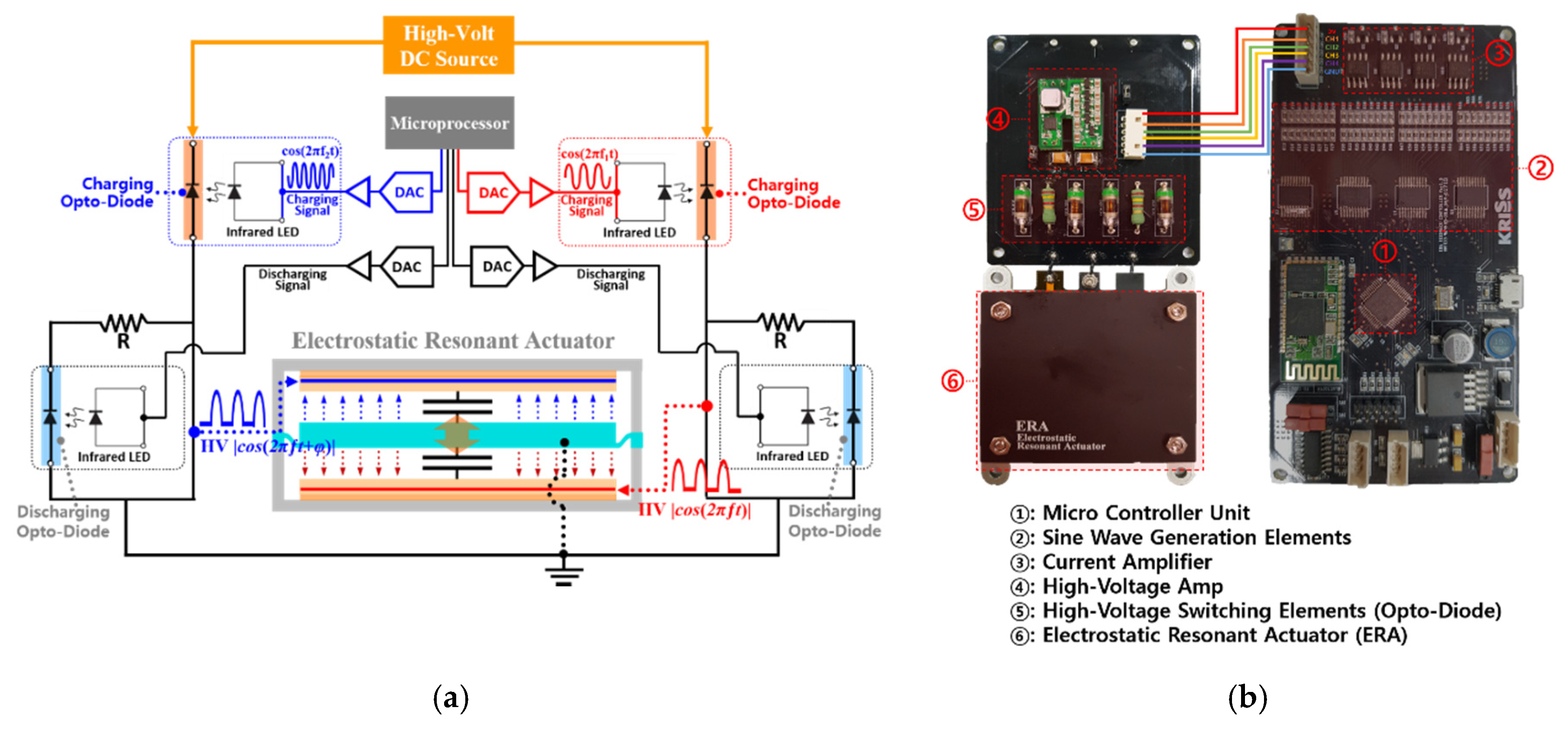
To power the electrodes and control the oscillation frequency of the module, a custom controller with a high voltage amplifier was also fabricated. The controller is necessary to alternate the powering of the electrodes in the duel-electrode actuator. The timing between each electrode activation must be accurate and consistent, making the controller highly important for the proper function of the dual-electrode ERA. The high voltage amplifier is necessary to amplify control signal inputs, which are less than 5 volts, producing the high voltage inputs required to effectively power the electrodes and activate the actuator. Figure 4a shows the schematic structure of a circuit diagram for the controller and high voltage amplifier. These are used in combination to provide two alternating high voltage cosine signals of the same frequency to the ERA module. Ensuring that the signals provided to the electrodes are equal in magnitude and frequency is important to produce the optimal vibration performance. For the proposed ERA module, 2 kV is required for each electrode. A portable rechargeable battery, meant to act as the power source for a large touchscreen, transmits an input signal of 2 V to the high voltage amplifier which converts it to the required amount of 2 kV. This in tandem with the custom controller ensures that the ERA module functions properly and has sufficient input power.

4. Experimental Evaluations

This section presents experimental evaluations of the actuators, and it compares their performance in terms of resonant vibration intensities. Static and dynamic experiments were first conducted on both ERAs to identify the actuator parameters, such as the stiffness, resonant frequency, damping ratio, and mass. The vibration performance of the dual-electrode ERA was measured and compared under different electrode configurations to study the effect that electrode activations had on performance. The performance of the single-electrode ERA was also compared to the dual-electrode ERA when both electrodes in the module were activated.

4.1. Experimental Identification of Actuator Parameters

Before conducting a comparison study of the actuators, their parameters need to be identified to verify the design and to ensure that they are comparable systems. Thus, this study conducted static and dynamic testing to experimentally determine key parameters, such as the natural frequency, damping ratio, and spring constant. In the static testing, the actuator remained unpowered, and a dynamic mechanical analyzer (DMA) was used to measure the stiffness of the actuator’s radial springs. In the dynamic testing, the actuator was excited to measure the natural frequency and damping ratio. To find the natural frequency of the system, a sine chirp signal was run through each actuator from 50 to 250 Hz over 10 s and the acceleration response was recorded using an accelerometer, seen in Figure 5a. By taking the Fourier transform of the experimental response data, the natural frequency was determined to be around 129 Hz for the single-electrode actuator and around 134 Hz for the dual-electrode actuator. The half-power method was used on the frequency response plots to estimate the damping ratio. The damping ratios for the single-electrode and dual-electrode ERAs were estimated to be 0.0143 and 0.0141, respectively.
Figure 5b shows the dynamic mechanical analysis testing setup. The actuators were mounted onto the DMA machine’s baseplate to secure them during testing. The DMA machine’s driveshaft applied a sinusoidal force input onto the movable mass while measuring its displacement. Using Hooke’s Law, the spring constant of the radial beam springs was calculated to be 16.62 kN/m. Although the actuators were fabricated with identical parameter values, they have slightly different natural frequencies and damping ratios. Small discrepancies in the actual and the theoretical design values were attributed to variations in the thickness of the raw materials and material property changes caused by high precision manufacturing processes, such as the wire-cutting of the slots for the beam springs. Nonetheless, the discrepancies were deemed to be negligible, and the two actuators were considered comparable.

4.2. Experimental Results of Actuator Performance

Following the actuator characterization study above, the actuators’ vibrotactile performance was experimentally evaluated to study the effect of the electrode configurations and to compare the performance of the proposed dual-electrode ERA with that of the single-electrode ERA. To properly activate the actuators, a total of three different input signals were generated by the controller, which can be visualized in Figure 6. When powering the single-electrode actuator, a positively offset sine input signal was used, as seen in Figure 6a. However, when using the dual-electrode ERA, this waveform could not be inputted into both electrodes without causing interference. To ensure there was no interference of electrostatic forces generated between the two electrodes, they needed to have proper input signals and configuration. Thus, half period sine waves, seen in Figure 6b, were inputted into each electrode with a phase difference relative to one another. These inputs could be used simultaneously to activate both electrodes without any interference.
As seen in Figure 7, the dual-electrode actuator’s resonant frequency was slightly higher than that of the single-electrode actuator because of the variations in their manufacturing discussed earlier. The figure further shows that the dual-electrode actuator produced a higher maximum acceleration of 14.32 g-forces at its resonant peak, compared to the single-electrode actuator which produced a maximum of 8.27 g-forces at its resonant frequency. Thus, the dual-electrode ERA with both electrodes activated produced a significantly greater vibration intensity compared to the single-electrode ERA, producing over 6 g-forces more, or a 73% increase, at their maxima. The results indicate that the dual-electrode configuration with proper control can substantially increase vibration intensities in a comparable actuator with a single electrode.
The dual-electrode ERA was studied to investigate the effect of electrode activations and the impact that the hole in the top electrode had on its performance. In the dual-electrode ERA, the two electrodes can be activated individually or simultaneously with the input signals at a phase difference. An inevitable hole was made in the top electrode to allow an accelerometer to be mounted directly onto the actuator’s mass. Placing the accelerometer directly onto the mass was highly important in this study to properly evaluate vibration performance. The hole made in the top electrode resulted in an approximate 20% reduction in the electrode area. Based on the fact that the attraction force produced by electrostatic plate actuators changes proportionally with the electrode area, the hole in the top electrode was expected to lower performance. Thus, the effect that the hole had on the performance was examined as a part of this study. Note that, in real-world applications, the hole is not necessary, so the performance of the actuator would not be compromised by such an alteration.
Figure 8 shows the experimental results of the dual-electrode ERA operated on various electrode activation conditions. The actuator generated the strongest vibrations when both electrodes were activated, producing a maximum of 14.32 g-forces compared to the top and bottom’s 4.97 g-forces and 7.62 g-forces, respectively. When only the bottom electrode was activated, which had no hole, the actuator performed similarly to the single-electrode actuator, confirming that the manufacturing variations did not cause a significant difference between the actuators. As previously hypothesized, the top electrode with a hole performed worse than the bottom electrode. The top electrode generated a maximum of 4.97 g-forces compared to the bottom electrode’s maximum of 7.62 g-forces: 35% lower. This finding is consistent with our hypothesis when fabricating the electrode. The hole in the top electrode has a clear effect on the dual-electrode ERA’s performance. It can, therefore, be reasonably inferred that if the actuator was fabricated for optimal use and a hole was not made in the top electrode, the dual-electrode ERA’s performance with both electrodes activated would exceed its current maximum of 14.32 g-forces. In summary, the proposed dual-electrode actuator’s performance when only using the top electrode with a hole was worse than its performance when using the bottom electrode only. The dual-electrode actuator’s performance when activating only the bottom electrode without a hole was similar to the single-electrode actuator, indicating that variances caused by manufacturing did not significantly impact the ERA’s performance.
To further evaluate the actuators’ performance, a “mock-up” display panel test setup was employed. The purpose of this evaluation was to compare the performance of the single and dual-electrode actuators when they were mounted onto a small tablet-sized rectangular panel. Note that the scope of this study was not to evaluate the performance of the actuators on large displays, but rather to examine the effect of the electrode configurations in ERAs. Thus, more comprehensive, full-scale large display testing will be conducted in a future study. Figure 9 shows the mock panel test setup. As shown in Figure 9a, the single-electrode ERA was mounted onto the bottom of a fabricated mock-up panel, which is supported by ultra-soft silicone supports at its four corners. An accelerometer was mounted onto the top surface of the panel to measure the output vibration intensity at the display surface, created by the ERA. Figure 9b shows the equivalent dual-electrode ERA setup. For both tests, the input signals described earlier were used.
Figure 10 shows the frequency response results of the panel testing. As seen in the figure, the resonance peak occurs at 158 Hz for both testing cases. The results show that the dual-electrode ERA produced a consistently higher vibration intensity throughout the entire frequency range considered in this study. Furthermore, the dual-electrode actuator produced a higher maximum acceleration (3.88 g-forces at 158 Hz) compared to the single-electrode actuator, which produced a maximum of 2.36 g-forces at 158 Hz. Similar to the actuator-only testing, the additional electrode increased the maximum intensity by 1.52 g, or nearly 65%, compared to the single-electrode actuator. In short, the dual-electrode ERA, with both electrodes activated, outperforms the single-electrode counterpart in producing the maximum peak vibration intensity even when mounted on an external mass. Note that Pacinian Corpuscles are most sensitive to sinusoidal vibrations around 150–160 Hz and that the detection threshold value for fingertip of vibration feedbacks is around 0.05 g [17,18]. The mock-up panel testing results showed that the developed dual-electrode ERA is resonant at 158 Hz, which is the most sensitive area for humans, and it can generate a vibration output 77 times greater than the activation threshold. Thus, the results indicate that the proposed dual-electrode ERA can provide sufficiently strong haptic sensations.
The proposed dual-electrode ERA can generate significantly improved vibration feedback than single-electrode ERA, making it more suitable for a large touch-sensitive display (TSD) requiring large vibration haptic feedback. The double electrode ERA is a thin plate structure, so multiple ERAs can be mounted on the back of the large TSD for conveying enhanced haptic feedback to users. Figure 11 illustrates this concept that multiple dual-electrode ERAs can be used to generate for the large TSD.

5. Conclusions

In this study, a new dual-electrode electrostatic resonant actuator (ERA) was proposed as a means to provide meaningful vibrotactile haptic feedback in large touchscreen display applications. A prototype dual-electrode ERA and custom controller were fabricated and compared to the single-electrode design to determine how the electrode configuration impacted the performance. The parameters of both actuators were experimentally measured, and the systems were determined to be comparable. The additional electrode added in the dual-electrode ERA led to a 73% increase in the maximum vibration intensity when compared to the single-electrode actuator. The top electrode in the dual-electrode actuator, when activated alone, produced a 35% lower vibration intensity compared to the bottom electrode, which can be attributed to the hole made for mounting the accelerometer. The actuators were also tested on a 100 g mock-up panel. The dual-electrode ERA produced a maximum intensity of nearly 65% greater than the single-electrode ERA. In summary, the dual-electrode ERA outperforms its single-electrode counterpart in all testing cases. These results show promising potential for the use of the dual-electrode electrostatic resonant actuator in generating vibrotactile feedback for large touch displays. In future extensions of this study, one or more dual-electrode actuators will be tested on actual touchscreen displays (>12 in) in multiple configurations to evaluate their vibrotactile feedback performance.

Author Contributions

Conceptualization, T.-H.Y., Y.-M.K., and J.-H.K.; methodology, T.-H.Y. and J.-H.K.; validation, T.M., T.-H.Y., J.-H.K. and Y.-M.K.; formal analysis, T.M. and J.-H.K.; resources, Y.-M.K. and T.-H.Y.; writing—original draft preparation, T.M.; writing—review and editing, T.-H.Y., Y.-M.K. and J.-H.K.; visualization, T.-H.Y. and Y.-M.K.; supervision, J.-H.K.; project administration, Y.-M.K.; funding acquisition, T.-H.Y. and Y.-M.K. All authors have read and agreed to the published version of the manuscript.

Funding

This research was funded by a research grant from the Korea Institute of Oriental Medicine, grant number KSN2012110.

Conflicts of Interest

The authors declare no conflict of interest. The funders had no role in the design of the study; in the collection, analyses, or interpretation of data; in the writing of the manuscript, or in the decision to publish the results.

References

  1. Bhalla, M.R.; Bhalla, A.V. Comparative Study of Various Touchscreen Technologies. Int. J. Comput. Appl. 2010, 6, 12–18. [Google Scholar] [CrossRef]
  2. Onishi, J.; Sakajiri, M.; Miura, T.; Ono, T. Fundamental Study on Tactile Cognition through Haptic Feedback Touchscreen. In Proceedings of the 2013 IEEE International Conference on Systems, Man, and Cybernetics, Manchester, UK, 13–16 October 2013; Institute of Electrical and Electronics Engineers (IEEE): NW Washington, DC, USA, 2013; pp. 4207–4212. [Google Scholar]
  3. Silfverberg, M. Using Mobile Keypads with Limited Visual Feedback: Implications to Handheld and Wearable Devices. In Human-Computer Interaction with Mobile Devices and Services; Chittaro, L., Ed.; Springer Science and Business Media LLC: Berlin/Heidelberg, Germany, 2003; pp. 76–90. [Google Scholar] [CrossRef]
  4. Banter, B. Touch Screens and Touch Surfaces Are Enriched by Haptic Force-Feedback. Inf. Disp. 2010, 26, 26–30. [Google Scholar] [CrossRef]
  5. Weddle, A.B.; Hua, Y. Confirmation Haptics for Automotive Interfaces Immersion—Haptic Technologies. 2013. Available online: www.immersion.com/ (accessed on 26 May 2020).
  6. Hoggan, E.; Brewster, S.; Johnston, J. Investigating the Effectiveness of Tactile Feedback for Mobile Touchscreens. In Proceedings of the SIGCHI Conference on Human Factors in Computing Systems, Florence, Italy, 5–10 April 2008; Association for Computing Machinery: New York, NY, USA, 2008; pp. 1573–1582. [Google Scholar] [CrossRef]
  7. Hausberger, T.; Terzer, M.; Enneking, F.; Jonas, Z.; Kim, Y. SurfTics-Kinesthetic and Tactile Feedback on a Touchscreen Device. In Proceedings of the 2017 IEEE World Haptics Conference (WHC), Munich, Germany, 6–9 June 2017; Institute of Electrical and Electronics Engineers (IEEE): Piscataway, NJ, USA, 2017; pp. 472–477. [Google Scholar] [CrossRef]
  8. Automotive. Immersion—Haptic Technology. Available online: https://www.immersion.com/automotive/ (accessed on 2 June 2020).
  9. Kaaresoja, T.; Anttila, E.; Hoggan, E. The Effect of Tactile Feedback Latency in Touchscreen Interaction. In Proceedings of the 2011 IEEE World Haptics Conference, Istanbul, Turkey, 21–24 June 2011; Institute of Electrical and Electronics Engineers (IEEE): Piscataway, NJ, USA, 2011; pp. 65–70. [Google Scholar] [CrossRef]
  10. Pyo, D.; Yang, T.-H.; Ryu, S.; Kwon, N.-S. Novel linear impact-resonant actuator for mobile applications. Sens. Actuators A Phys. 2015, 233, 460–471. [Google Scholar] [CrossRef]
  11. Koo, J.-H.; Schuster, J.M.; Tantiyartyanontha, T.; Kim, Y.-M.; Yang, T.-H. Enhanced Haptic Sensations Using a Novel Electrostatic Vibration Actuator with Frequency Beating Phenomenon. IEEE Robot. Autom. Lett. 2020, 5, 1827–1834. [Google Scholar] [CrossRef]
  12. Laitinen, P.; Mawnpaa, J.; Mäenpää, J. Enabling Mobile Haptic Design: Piezoelectric Actuator Technology Properties in Hand Held Devices. 2006 IEEE International Workshop on Haptic Audio Visual Environments and their Applications (HAVE 2006), Ottawa, ON, Canada, 4–5 November 2006; Institute of Electrical and Electronics Engineers (IEEE): Piscataway, NJ, USA, 2006; pp. 40–43. [Google Scholar] [CrossRef]
  13. Johnstone, R.W.; Parameswaran, M. (Eds.) Electrostatic Actuators. In An Introduction to Surface-Micromachining; Springer: Boston, MA, USA, 2004; pp. 135–152. [Google Scholar] [CrossRef]
  14. Schuster, J.M. Modeling and Simulation of a Novel Electrostatic Beat Actuator for Haptic Feedback in Touch Screens; Miami University: Oxford, OH, USA, 2018. [Google Scholar]
  15. Joo, Y.; Shin, E.-J.; Heo, Y.; Park, W.-H.; Yang, T.-H.; Kim, S.-Y. Development of an Electrostatic Beat Module for Various Tactile Sensations in Touch Screen Devices. Appl. Sci. 2019, 9, 1229. [Google Scholar] [CrossRef] [Green Version]
  16. Feynman, R.P.; Leighton, R.B.; Sands, M. The Feyn-Man Lectures on Physics; Feynman lectures; Caltech. Edu.: Pasadena, CA, USA, 1965; Volume 33, p. 750. [Google Scholar]
  17. Ryu, J. Psychophysical Model for Vibrotactile Rendering in Mobile Devices. Presence Teleoperators Virtual Environ. 2010, 19, 364–387. [Google Scholar] [CrossRef]
  18. Morioka, M.; Whitehouse, D.J.; Griffin, M.J. Vibrotactile thresholds at the fingertip, volar forearm, large toe, and heel. Somatosens. Mot. Res. 2008, 25, 101–112. [Google Scholar] [CrossRef] [PubMed] [Green Version]
Figure 1. Electrode configuration of: (a) single-electrode actuator; (b) proposed dual-electrode actuator.
Applsci 10 05375 g001
Figure 2. Exploded view model and working principle design of the proposed electrostatic resonant actuator (ERA) module.
Applsci 10 05375 g002
Figure 3. (a) FEM simulation to determine the spring stiffness; (b) fabricated ERA module separated by part.
Applsci 10 05375 g003aApplsci 10 05375 g003b
Figure 4. (a) Schematic of a circuit diagram for the controller and high voltage amplifier; (b) fabricated controller and high voltage amplifier.
Applsci 10 05375 g004
Figure 5. (a) Acceleration testing setup used to measure the actuator’s damping ratio; (b) dynamic mechanical analyzer (DMA) testing setup used to measure the actuator’s spring stiffness.
Applsci 10 05375 g005
Figure 6. Input signals used in the experimental setup: (a) single-electrode ERA offset sine input; (b) dual-electrode ERA upper and lower electrode inputs.
Applsci 10 05375 g006
Figure 7. Experimental acceleration response of single-electrode actuator and dual-electrode actuator.
Applsci 10 05375 g007
Figure 8. Experimental acceleration response of the dual-electrode actuator powering the bottom, top, and both electrodes.
Applsci 10 05375 g008
Figure 9. Experimental setup for measuring the output vibration intensities of the ERAs on mock-up panels: (a) test setup of the single-electrode ERA on a 100 g panel, (b) test setup of the dual-electrode ERA on a 100 g panel.
Applsci 10 05375 g009
Figure 10. Experimental acceleration response of the single-electrode ERA and the dual-electrode ERA on the 100 g mock-up panels.
Applsci 10 05375 g010
Figure 11. An illustration of dual-electrode ERA modules for a touch-sensitive display.
Applsci 10 05375 g011
Table 1. Parameters used for the proposed ERA module’s fabrication.
ParameterNotationUnitValue
Mass m g 25
Stiffness k k N / m 17.15
Bottom Surface Area of Moveable Mass A m m 2 2375.83
Air Gap d a i r m m 0.30
Thickness of Dielectric Film t D i e l e c t r i c m m 5.50 × 10 2
Vacuum Permittivity ε 0 F / m m 8.85 × 10 15
Relative Permittivity of Air ε r 1.00
Relative Permittivity of Dielectric K e 3.40
Input Voltage Signal Amplitude V V 2000

