1. Introduction
During the last decades, the growing demand for the utilization of lightweight, high-performance structural composite materials has rapidly increased in various commercial sectors, such as the aerospace and automotive industries. Fiber reinforced polymers constitute an extremely interesting field of research due to their potential for the exploitation of additional functionalities. Tailoring or “architecting” the material in relation to both its structural and non-structural services is an inherent ability of advanced composites and is rapidly emerging technology for their next generation. Understanding their mechanical behavior requires the study of the interface, the common physicochemical areas between the distinct phases (reinforcing and matrix materials) [
1,
2]. This is a prerequisite for the design of a composite material, as its behavior is most of the times governed by its interfacial properties [
3].
The approach of blending nano-scaled reinforcements into the matrix of micro-scale reinforced systems, with a view to enhancing both the matrix dominated properties as well as imparting multifunctionality, has been extensively studied in the last decade. Additional functionalities include both capabilities that relate to structural integrity, such as wear resistance, morphing, or self-healing, as well as non-structural ones, such as inherent structural health monitoring, sensing and actuation, power harvesting, and power storage [
4,
5,
6,
7].
In an alternative approach, the nanomaterials are deposited directly onto the surface of reinforcing fibers, such as carbon, aramid, and glass fibers (GFs), and this has triggered a new class of functional materials, where the nanoscale functional reinforcement is following the architecture of the microscale reinforcement. This leads to a biomimetic ‘hierarchical’ approach towards multiscale reinforcements with improved wettability, increased adhesion, robust interlocking mechanisms, and enhanced interfacial stress transfer related to the introduction of nanophases such as carbon nanotubes (CNTs) [
8,
9,
10,
11,
12]. The resultant hierarchical interphases except for the modified mechanical properties also transfuse extra functionalities [
13,
14,
15,
16,
17].
Du and co-workers presented a synergistic strategy by taking advantage of polyetherimide (PEI) and ZIF-67 to enhance the interfacial strength of carbon fiber (CF) reinforced polyetheretherketone (PEEK) composites via a facile route. After modification, the tensile strength of single CFs showed no deterioration and the interfacial shear strength (IFSS) of the as-prepared modified CF/PEEK model composites revealed an increase of 40.5% [
18]. De Luca et al. [
19] developed nanostructured ordered “brick-and-mortar” interphases using layer by layer deposition of PDDA/(PSS/LDH)
25 solution onto the surface of hydroxylated GFs. The resulting anisotropic morphology caused strain hardening phenomena to the produced nanostructured interphases and thus reduced the local stress concentrations arising from fiber breaks and increased the extent of stable fiber slippage. Pozegic et al. presented a scalable method for growing CNTs during either the CF fabrication or the CF surface treatment stage, that could potentially further minimize their damage and offer a suitable replacement for the CF polymer sizing. Moreover, improvements in electrical conductivity in all three directions with significant enhancement in the surface (300%), thickness (450%) and volume (230%) were observed. Additionally, the thermal conductivity was improved by 107% in the through-thickness direction [
20]. Another study documented the strongly orthotropic electrical properties of composite materials comprised of hierarchical UD GFs coated with single-walled carbon nanotubes (SWCNTs). The exceptional damage-sensing capability of the SWCNTs hierarchical composites was predicted by simulations and validated experimentally [
21].
CNTs dispersed-inks deposition onto fibrous substrates are capable of to convert insulating reinforcing fibers to semi-conductive reinforcements for composites with modified interfacial shear strength (IFSS) and secondary additional properties. The resulting composite materials can be used for a wide range of applications, such as electrostatic charge dissipation, damage sensing, and energy harvesting. Gao et al. reported on the strain, humidity and temperature sensing ability of hierarchical GFs, coated with commercial oxidized CNTs by electrical measurements [
22]. Tzounis et al. systematically examined the thermoelectric response of reinforcing fibers coated with CNTs [
23], thermoelectric materials based on engineered polymer nanocomposites, and/or polymer/fiber composites [
14,
24], appropriate for large-scale structural applications with thermal energy harvesting capabilities.
It is common knowledge that energy loss is inevitable during the operation of an engine resulting in a fuel efficiency less than 50%. Most of the wasted energy is in the form of heat. For typical diesel engines, tests from as early as 2009 showed that, the heat lost by the exhaust was approximately a quarter of the energy produced by the utilized fuel [
25]. Thermoelectric energy harvesting and pyroelectric energy harvesting exploitation, relying on the temperature change over distance and time, respectively. The aforementioned technologies constitute the two most common thermal energy harvesting methods. Thermoelectric (TE) conversion is a promising technique to recover temperature waste heat as electricity. In general, heat coming from temperature fluctuation in the environment can be reclaimed as electricity on account of the well-known ‘Seebeck effect’. Thermoelectric materials exhibit the Seebeck effect, in which charge carriers move in response to temperature gradients. The Seebeck coefficient is directly related to the density of states, whereas the electrical conductivity can be limited by electronic and morphological defects. Charge carriers diffuse across the temperature gradient, creating an accumulation of charge and thus a potential difference, Δ
V. The magnitude of this effect is described by the Seebeck coefficient (
S) and is simply the voltage difference divided by the applied thermal gradient
S = Δ
V/Δ
T. The Seebeck coefficient is further used for the calculation of the power factor (
PF =
σ ×
S2), a well-established quantity for comparing the TE performance of different thermoelectric materials. Finally, the overall thermoelectric efficiency for specific temperature range applications of a material is classified by the dimensionless thermoelectric figure of merit,
ZT (
ZT = (
σ ×
S2) ×
T/
κ), where
σ is the electrical conductivity,
S is the Seebeck coefficient,
κ is the thermal conductivity and
T is the corresponding temperature.
An efficient thermoelectric material presents a high value of ZT, combining high electrical and poor thermal conductor characteristics. The three thermoelectric parameters
σ,
S and
κ are correlated with the intrinsic carrier concentration of the material [
26,
27,
28,
29]. Thermoelectric energy harvesting is a conventional technique for converting wasted thermal energy into the electrical power by means of thermoelectric element generators (TEGs). A typical TEG device consists of p–n junctions properly interconnected electrically in series and thermally in parallel. When a temperature gradient is established between the hot and the cold side, free electrons and holes are able to move towards specific directions and generate a potential difference proportional to the temperature difference between the p-type and n-type semiconductors. Compared to the traditional TEG devices, high performance flexible TEGs that exploit the nanotechnology advancements are being extensively reported [
17,
30].
In this study, hierarchical glass fiber tows coated with p-type and n-type SWCNTs as well as reference tows were evaluated in terms of their thermal stability and physicochemical relevance with the epoxy resin. The thermoelectric response of the produced p and n-type epoxy model composites have been assessed for a single pair TEG fabrication. The tow pull-out test was used to determine the quality of interfacial bonding between the epoxy matrix and the nanocoated glass fibers. Fracture morphologies of the pulled-out tows obtained via optical microscopy revealed a cohesive type of failure in all cases, as the epoxy material remained attached on the surface of the tows after the pull-out process.
2. Materials and Methods
2.1. Materials
The 1062 Multi-End Roving (NEG) GFs were employed for this study with a tensile strength of 2300–2400 MPa and tensile modulus of 72 GPa, specifically designed for use with epoxy resin systems in applications that require high mechanical strength and corrosion resistance such as filament wound pipes. The filament diameter is 13.3 #xB1; 0.6 μm as stated by the manufacturer.
SWCNTs in powder form were provided by OCSiAl (TUBALL, carbon content: >85 wt.%, outer mean diameter of CNT 1.8 ± 0.4 nm, length of CNT > 5 μm, metal impurities <15 wt.%). SDBS (sodium dodecylbenzenesulfonate, 348.48 g/mol), PEI (Poly(ethyleneimine)) solution ~50% in H2O (Mr 600,000–1,000,000) were purchased from Sigma Aldrich. All chemical reagents were used as received.
RS Pro silver loaded epoxy conductive paste was utilized for the adhesive ohmic contacts.
A commercial low viscosity liquid epoxy resin system was employed, consisting of EPIKOTE Resin 828LVEL (100.0 parts by weight) EPIKURE™, Curing Agent 866 (83.0 parts by weight), and EPIKURE™ Catalyst 101 (1.5 parts by weight). The curing cycle and post-curing included heating at 90 °C for 90 min and at 130 °C for 180 min, respectively.
2.2. Dispersion and Deposition of the TE p and n-Type SWCNTs Inks onto GF Tows
The SWCNTs were dispersed using the UP400S manufactured by Hielscher Ultrasonics tip-ultrasonic probe processor for 45 min at 10 a Watt amplitude to deliver the wave directly into the aqueous solvent. For the p-type TE ink, 2 mg/mL SWCNTs and 5 mg/mL of SDBS were utilized in order to produce a suspension with a proper critical micelle concentration (CMC) and achieve a stable dispersion. Accordingly, for the n-type TE ink, 2 mg/mL SWCNTs and 2 mg/mL of SDBS coupled with 5 mg/mL of poly(ethyleneimine) were used. The notation “p-type and n-type” refers to the type of the charge carriers induced in the two different formulations of the CNTs and does not imply any type of substitutional doping of the CNTs.
Then, the p and n-type TE inks were used for coating of the GF tows via a simple blade coating process. In more detail, 10 cm long single GF tows were cut from the reel, stabilized, and coated towards the creation of homogeneous continuous TE efficient p-type and n-type films onto the GFs. After the coating process, the tows were left to dry on a hot plate at 90 °C for 30 min.
2.3. Manufacturing of Model Composites for Thermoelectrical Characterization
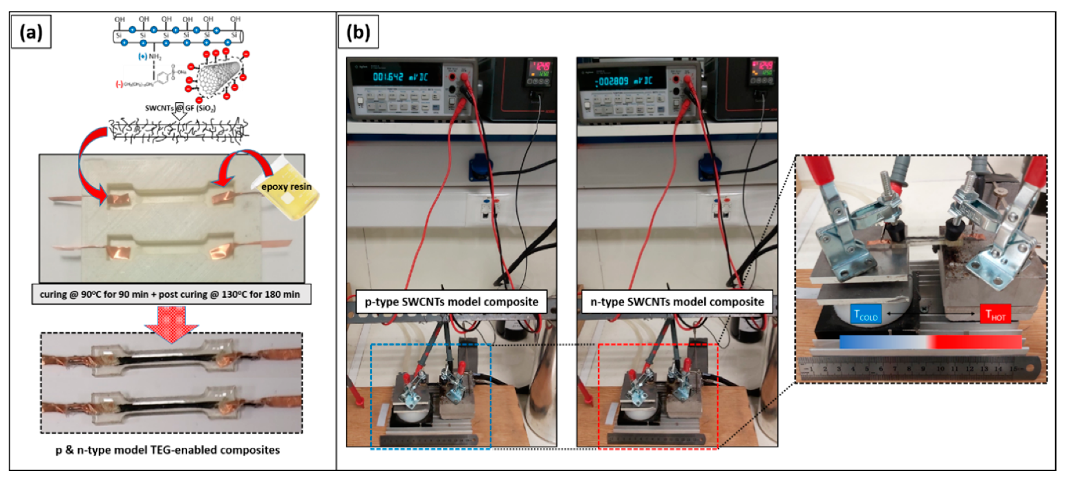
Model composites were prepared and characterized for the study of the effect of the epoxy resin system addition on the thermoelectric response of the coated glass fibers. The coated single GF tows were placed flat onto a pre-cleaned silicon dog-bone shaped mould and secured in place on both sides with an adhesive tape. Then, two thin copper foil electrodes were adjusted tightly on each side of the functional single tows and glued with silver paste on the tow to ensure proper ohmic contacts. Upon drying of the contacts, a well-mixed and degassed epoxy resin/hardener/catalyst mixture was casted in the mould, which impregnated thoroughly the whole GF tow. The system was cured and post-cured following the aforementioned protocol. At least five model composites for each category were fabricated and the mean experimental values with the corresponding standard deviations are presented. The electrical properties and the thermoelectric response of the model composites were measured with the set up that is displayed in
Figure 1.
2.4. Preparation of Model Composite Specimens for Micromechanical Tests
Tests for the interfacial shear strength calculations were performed on single GF tows using a pull-out configuration. These tests were performed in order to evaluate the effects of the nanostructured coatings on the interfacial mechanical properties between the hierarchical fibers and the epoxy resin system.
For the selected manufacturing process, both uncoated and nanocoated GF tows with a length of 100 mm were pre-impregnated with a thin layer of epoxy resin at 3/4 of their length, using a micro-pipette and were semi-cured until the resin was viscous enough so as not to leak from the impregnated tow.
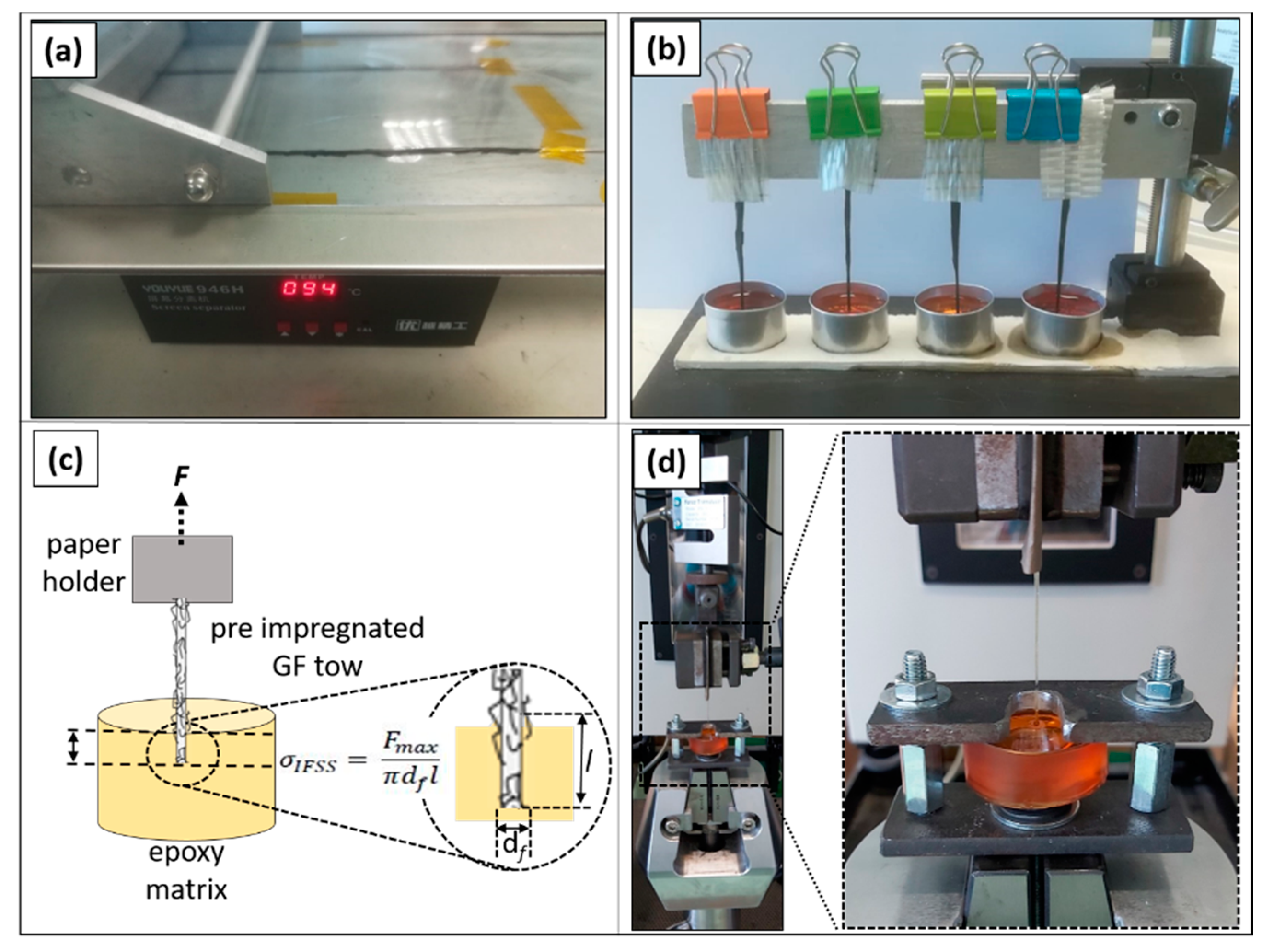
These epoxy resin semi-cured tows were lowered into the aluminum moulds by using purposely made fixture is presented in
Figure 2b. The fixture was designed so as to hold the pre-impregnated tows aligned during the thermal treatment of the resin. Then, 20 g of the resin/hardener/catalyst system were poured into each of the aluminum moulds. Particular attention was paid in order to avoid buckling of the tows and simultaneously maintain the impregnated embedded length in the range of 1–2 mm. Finally, the specimens were cured and post cured according to the recommended curing cycles.
The tow pull-out experiments were conducted at room temperature using the Universal Testing Machine by Jinan Testing Equipment IE Corporation (Jinan, China) with a 2 kN Load cell. A two-piece metal jig held the epoxy resin mould while the top part was clamped using the appropriate jaw faces. A constant cross-head speed of 5 mm/min was employed for tensile loading to induce the pull out shear force at the tow/resin interphase. Tests were considered successful when the GF tow was completely pulled out from the polymer matrix. The applied load (F) and the corresponding displacement were recorded and the interfacial shear stress (σIFSS) was calculated using the equation σIFSS = Fmax/π × df × l, where Fmax is the maximum load prior to the fracture of the GF tow, df is the diameter-width of the tow, and l is the embedded length, including the meniscus, as determined by optical microscopy.
The apparent interfacial shear strength of the functional GF tows and the epoxy resin matrix was calculated and compared with reference uncoated GF tow model composites. The mean values of shear strength presented correspond to the average of 8 successful pull-out experiments for each type of specimens. Finally, the surface morphology of the pulled-out fiber tows from all categories was studied using an optical stereoscope at low magnification.
2.5. Characterization Techniques
Contact angle measurements were acquired via a commercial automated contact angle goniometer system manufactured by Ossila Ltd (Sheffield, UK).
The morphology of the hierarchical GFs, as well as the reference GFs were evaluated via SEM using the JEOL JSM 6510 LV SEM (JEOL Ltd., Akishima, Japan) with an operating voltage of 3.5 KV.
Thermogravimetric measurements were carried out in the STA 449C analyzer Netzsch-Gerätebau GmbH, Selb, Germany. The experimental procedure included a dynamic step from 25 to 1000 °C with a heating rate of 10 °C/min at ambient conditions to examine the reference and the nanocoated GFs mass loss.
The Labram HR-Horiba scientific micro-Raman system was used. The 514.5 nm line of an Ar + ion laser operating at a power of 1.5 mW at the focal plane was employed for the Raman excitation. An optical microscope equipped with a 50× long working distance objective served both for delivering the excitation light and collecting the back-scattered Raman light. Raman spectra in the range of 90–3500 cm−1 were collected.
In order to determine the basic electrical characteristics, p and n-type bucky paper films were prepared by overnight vacuum filtering of the respective SWCNTs dispersions and four probe sheet resistance measurements were conducted (
Table 1). A typical 4-probe technique (Four-Point Probe commercial system manufactured by Ossila Ltd.) was used to calculate the electrical conductivity based on the following formula:
σ = 1/
R ×
L/
S × (ln2/π), where
R is the measured 4 probe sheet resistance,
L is the length, and
S is the cross section of each sample. It should be mentioned that the employed four-point probe system with four equally-spaced, co-linear probes to the material (interelectrode probe distance/spacing: 1 mm) is capable of delivering currents between 10 nA and 150 mA, and can measure voltages from as low as 100 μV up to 10 V, which results in a sheet resistance measurement range of 3 mOhm/□ to 10 MOhm/□. The values reported are mean values of at least four measurements performed on different samples.
The DC measurements were conducted with a standard two-probe method using the Agilent 34401A multimeter with 6½ digits resolution. Model composites were placed and measured at 25 mm electrode-electrode distance at room temperature and 25% relative humidity (RH).
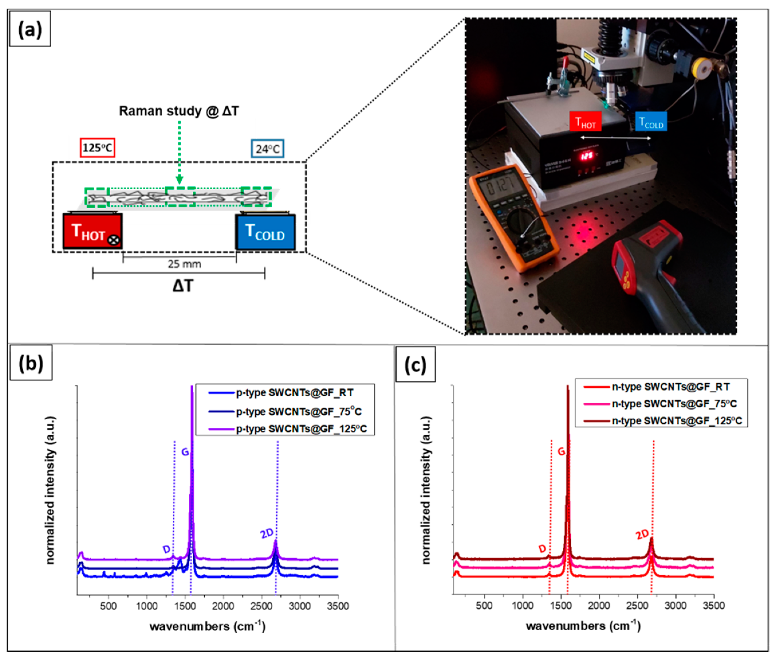
The voltage output of the model composites was determined using a custom-made setup. The samples were mounted on two metal blocks, which enabled the generation of a temperature difference. For all measurements, the one aluminum block (Tcold) was kept at room temperature (~24 °C) via mild water circulation, while the other one (Thot) was heated until 125 °C via calibrated temperature-controlled resistors, allowing for the generation of a temperature gradients. The generated thermovoltage (ΔV) was measured across the electrodes by a multimeter-voltmeter. The temperature of the two blocks was measured with an IR-thermometer (OMEGA OS-VIR50 Dual Laser Video IR Video Thermometer) to verify the temperature difference (ΔT), and the Seebeck coefficient (S) was derived from the ratio ΔV/ΔT.
4. Discussion
4.1. Surface Structure and Wettability of the Coated GF Tows
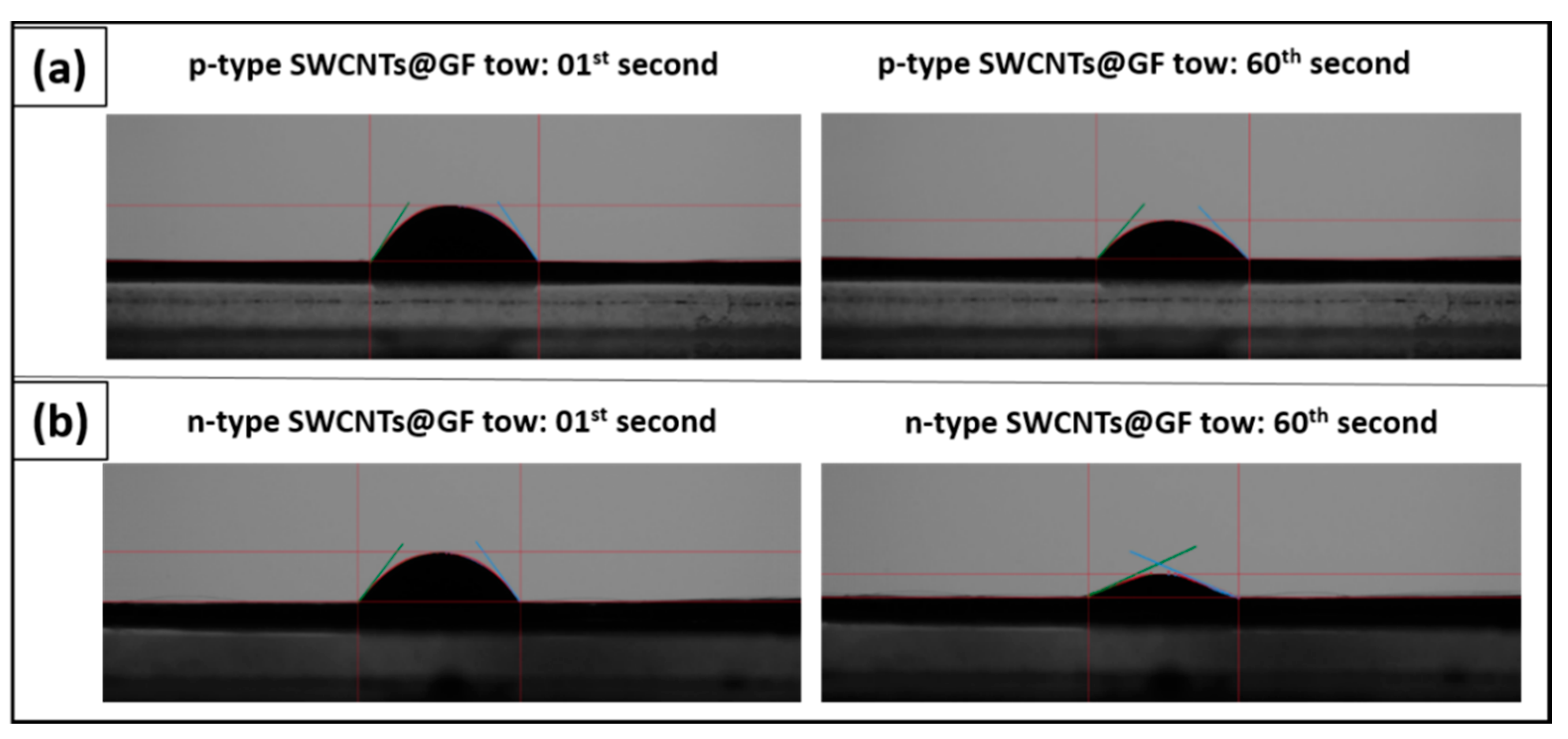
The good wetting of the glass fiber tows by both the p and n-type SWCNTs ink droplets is indicative of the inherent hydrophilic behavior of the glass fibers, which promotes the forming of a uniform SWCNTs film on the GFs and is a measure of the level of adhesion. In
Figure 3, images are shown for each case, captured just after the drop was suspended onto the surface of the glass fibers and also 60 s later to evaluate the progression of the wetting. For the GFs coated with p-type SWCNTs the average contact angle was found to be ca. 56.47° and for the n-type 52.39°.
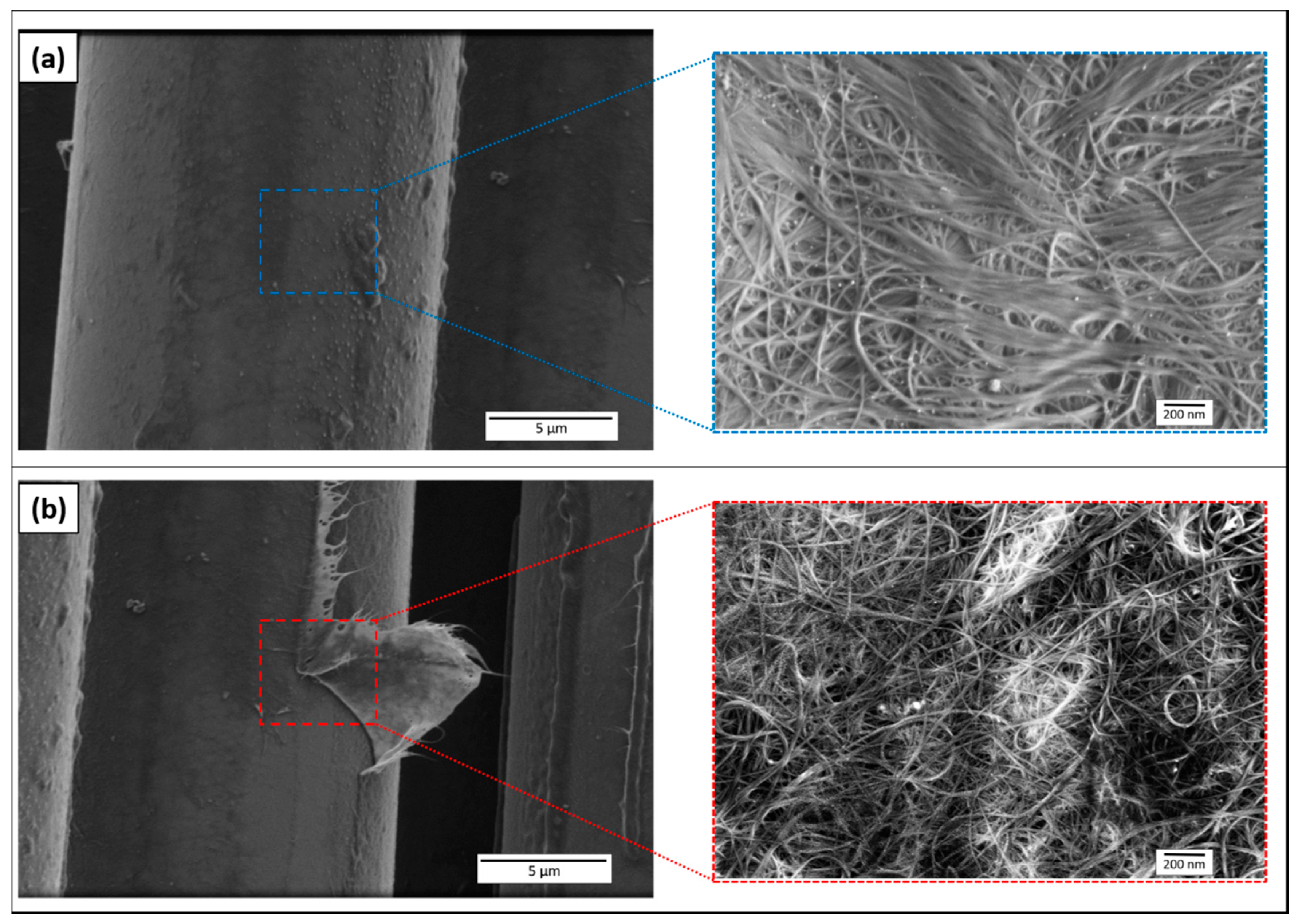
As was observed in the SEM study (
Figure 4), both the p- and n-type SWCNTs films formed on the GFs are satisfactorily uniform and dense exhibiting an interconnected network of SWCNTs which fully cover the surface. Some SWCNTs agglomerates are barely visible. The observed SWCNT–SWCNT junctions are impart the high values of electrical conductivity to the films, which alter the inherently dielectric behavior of the GF tows.
4.2. Thermal Stability of the Produced Coated GF Tows
Thermogravimetric analysis was used in order to characterize the thermal stability of the SWCNTs coated GFs in comparison to the reference GFs.
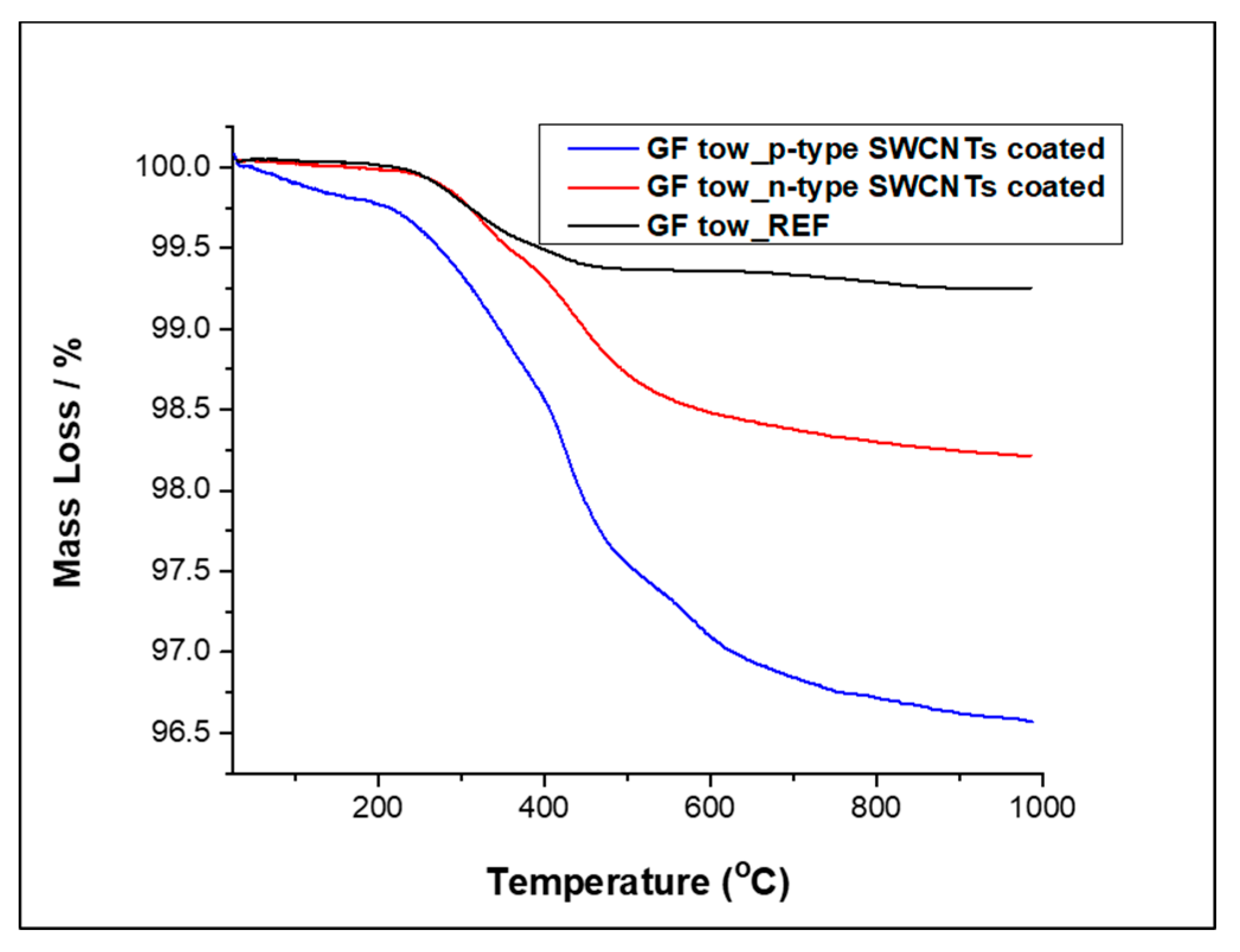
As depicted in
Figure 5, a minor mass loss in the order of almost 0.05% was observed for the reference GFs as well as for the n-type SWCNTs coated GFs above 100 °C and up to 241.5 °C and 213.2 °C, respectively. The p-type SWCNTs coated GFs depicted a similar behavior at that temperature range losing, however a slightly higher amount of its mass, namely 0.28% up to 175.3 °C. This mass loss is attributed to the evaporation of residual moisture for all the samples and is observed to be increased in the p-type SWCNTs coated GFs due to the increased amount of carboxy moieties. At higher temperatures, between about 241.5 °C and 539.2 °C the reference GFs lost 0.7% of their mass due to the combustion of the silane type sizing [
38,
39,
40]. Then, the mass of the E-glass fibers remained almost constant without considerable weight loss up to 1000 °C.
The thermal degradation of the p-type and the n-type molecular doped SWCNTs is a multistage process due to the existence of the various functional groups that are absorbed on their surface or are interacting with it. The functional chemical groups as moieties that SWCNTs contain are in general decomposed during the second temperature range that spans from roughly 200 °C to 500 °C. In more detail, the p-type SWCNTs exhibited the typical decomposition behavior of pristine SWCNTs that are inherently p-doped by a small amount of adsorbed oxygen containing groups. The oxygen-based moieties promote the electron withdrawing process from the CNT electron-rich back-bone, effectively introducing holes as main charge carriers (p-doping). The p-type SWCNTs coated GFs lost ca. 1% of their mass up to 373 °C that can be attributed to smaller in size oxygen containing functional groups like hydroxy and ether moieties. Another 1.35% mass loss was observed up to 531 °C that can be due to larger oxygen containing moieties like carboxyl and ester moieties [
41]. The initial mass loss of SDBS molecules is owing to burning with the presence of oxygen (330–450 °C) and the burning of the SDBS continued to occur above 800 °C [
42]. Overall, due to the fact that the SDBS concentration is lower (2 mg/mL) in the n-type SWCNTs coatings, this may also explain the loose of less weight compared to the p-type SWCNTs coatings (5 mg/mL). The observed loss amount is in agreement with the percentage of SDBS and CNTs that were used for the preparation of the inks. Additionally, any amorphous carbon that might be present into the SWCNTs coating would also be combusted at this temperature range. A further 0.7% mass loss occurred up to 756 °C that can be attributed to the combustion of the SWCNTs. Then, the mass of the underlying GFs remained almost stable up to 1000 °C with only a further 0.18% mass loss that can be attributed to some possible remaining percentage of catalyst particles from the production process of the CNTs [
43].
A slightly different behavior was presented by the n-type SWCNTs coated GFs. The decomposition of the nitrogen containing moieties that are included in the PEI molecules, which are entangled in between the CNT network, was responsible for the 0.53% mass loss from 213 °C up to 368 °C. A further 1% mass loss was observed up to 626 °C that is attributed the total decomposition of the SWCNTs. Afterwards the mass of the underlying GFs remained almost stable up to 1000 °C, with only a small amount equal to a further 0.24% being decomposed up to 1000 °C maybe on account of some possible remaining percentage of catalyst particles due to the production process of the CNTs [
43].
4.3. Raman Analysis of the TE-Enabled GF Tows
The p-type and the n-type SWCNTs coatings onto the GFs possess all the expected vibrational modes commonly encountered in graphitic materials. More specifically, the most prominent band of the spectrum of SWCNTs was the graphitic or G band with E
2g symmetry located at about 1590 cm
−1. The radial breathing mode, which is a unique phonon mode of SWCNTs was also observed at the 120 cm
−1 to 140 cm
−1 region. Another disorder-induced band appearing in the first order spectrum of the SWCNTs is the D band, at about 1340 cm
−1. The D band is caused by either amorphous carbon or sp
3 carbon atoms at defect sites on the CNT sidewalls [
44]. Furthermore, the 2D peak dominated the second order spectrum of the SWCNTs coatings. This band was located at about 2685 cm
−1. This overtone results from a double resonance process and is a symmetry allowed band which requires two phonons to be completed [
45,
46].
As can be seen in
Figure 6b,c, no changes were observed in the Raman spectra of both the p-type and the n-type SWCNTs coatings onto the GFs when they were subjected to temperature gradients of 50 °C and 100 °C, apart from minor positive frequency shifts of all vibrational modes which were attributed to the increased temperature. This result indicates that the hierarchical GFs which are coated with the organic SWCNTs inks of both p-type and n-type TE behavior are chemically and structurally stable.
4.4. Evaluation of the Model Composites Thermoelectric Efficiency
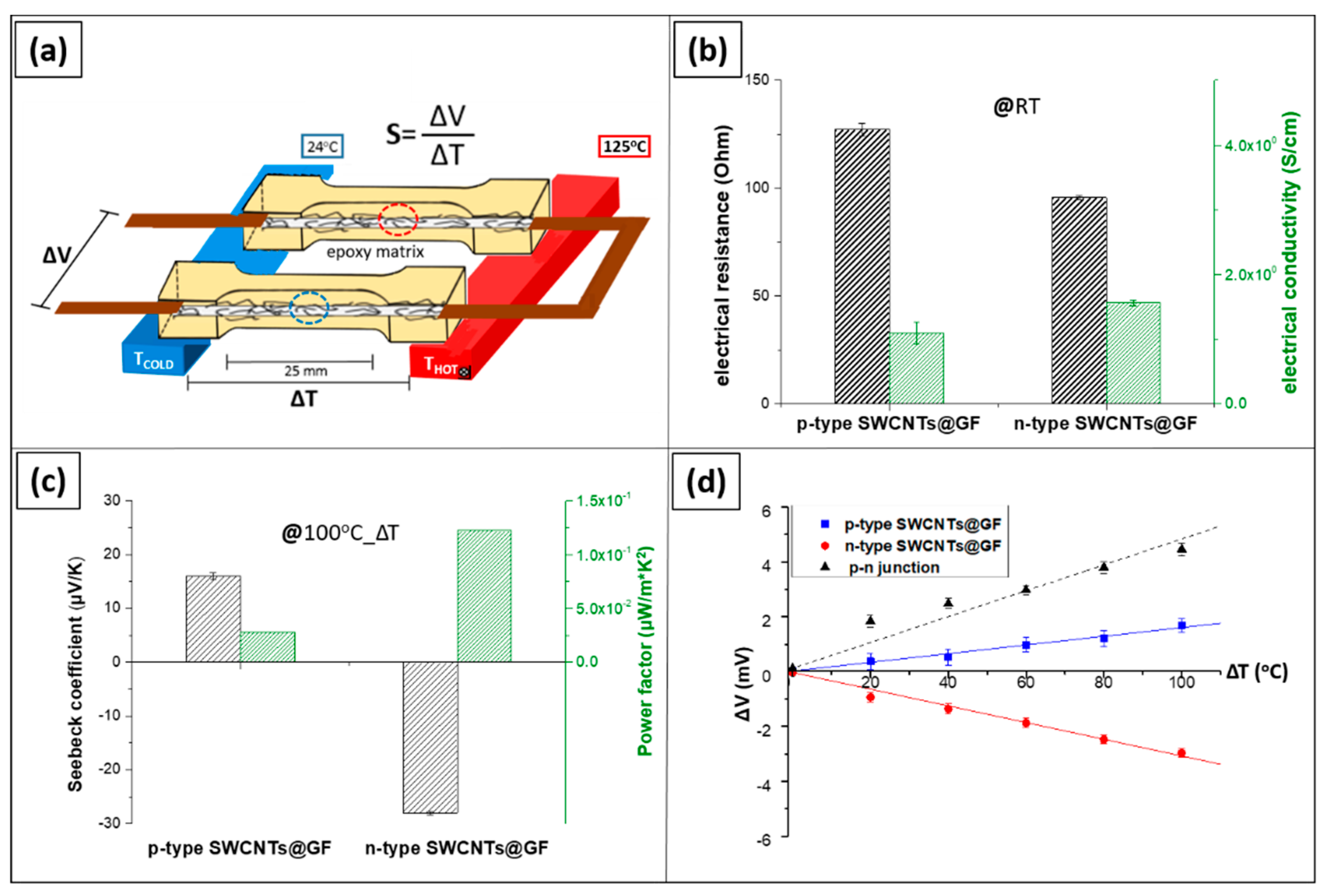
The electrical resistance as well as the electrical conductivity of the prepared model composites are presented in
Figure 7b. The p-type SWCNTs coated GF model composites exhibited electrical resistance of 127.2 ± 2.9 Ohm, which corresponds to electrical conductivity of 1.097 ± 0.05 S/cm, while for the n-type SWCNTs coated GF model composites showed very similar values i.e., 95.6 ± 1.1 Ohm and 1.561 ± 0.023 S/cm, respectively. The high electrical conductivity of the coated GFs is a key parameter for thermoelectric performance, since it can facilitate the flow of the thermally induced charge carriers upon being exposed to a temperature difference. Additionally, as aforementioned, low thermal conductivity is also desirable for the sustainability of the thermoelectric effect. In the case of the SWCNT interphase, it may also be postulated that the infusion of the thermally insulating epoxy molecules reduces thermal conductivity, thus further enhancing thermoelectric performance. More analytically, this mechanism creates a barrier at the SWCNTs junctions and prevents the direct physical contact between them resulting in reduced thermal energy transport. [
23,
29].
The Seebeck coefficient (
S = Δ
V/Δ
T) was derived from the slope of Δ
V vs. Δ
T curves by linear fitting.
Figure 7c shows the Seebeck coefficients of the p and the n-type model composites. For the p-type model composite, the Seebeck coefficient was found to be +16.2 ± 6 μV/K corresponding to a power factor of 0.02 μW/m∙K2 and for the n-type −28.4 ± 4 μV/K corresponding to a power factor of 0.12 μW/m∙K
2.
As was observed, the p-type SWCNTs coated GF model composites exhibited slightly lower values of Seebeck coefficient compared to the corresponding bucky papers. This can be attributed to the high nitrogen amount of the hardener within the epoxy system, acting as a n-dopant [
32]. On the other hand, for the n-type SWCNTs coated GF model composites the Seebeck coefficient values remain almost identical.
Figure 7d depicts the generated thermovoltage upon exposure to various values of Δ
T, for both p and n-type SWCNTs coated GF model composites. More specifically, the TE voltage of the in-series electrical and the in parallel thermal connection between the p-type and the n-type model composites creating a p–n junction are being displayed. As can be observed, within the studied temperature range, the generated voltage increased linearly with increasing temperature,
R2 > 0.98 for all cases. The measured voltage output was 4.46 ± 0.3 mV with a device resistance of 235.5 ± 2.5 Ohm at 100 °C Δ
T. The maximum output of the p–n model composites TEG device was calculated 0.02 μW at a temperature difference of 100 °C, according to the following equation
Pmax = Δ
V2/4 ×
RTEG [
24]. The derived maximum output power density of the device (p–n model composites pair) was 0.016 μW/cm
2.
Overall, the relatively high values of the electrical resistance were directly related to the area of the evaluated coated GF tows. It is expected that by increasing the area of the thermoelement (in this case the single coated GF tow), the electrical conductivity could be significantly increased while the Seebeck coefficient would not be affected as it is an inherent material property and is independent of the geometry of the evaluated specimen. To further elaborate on this statement, when the cross-sectional area of the coated substrate is increased, by increasing the thickness of the CNT coating on the GF substrate, its electrical resistance is reduced. Generally, the electrical resistivity of the CNTs films decreases as the thickness of the coatings is being increased. The property of the electrical resistivity highly depends on carrier concentration and carrier mobility, while the electrical resistance depends on the resistor shape geometry and the specific material. Electrical resistivity is an intrinsic property of a conductive film which is directly proportional to the total resistance R, an extrinsic quantity that depends on the length and cross-sectional area of the corresponding film. Larger cross section areas present lower values of electrical resistance. In the case of SWCNTs, changes within the conductive network due to thickness optimization are able to positively impact the electrical conductivity. Both cases are true until the bulk resistance value is reached, thereby no further increments in electrical conductivity can be achieved. There also exists an optimal area that produces the highest possible thermoelectric values, as it is able to host the highest possible electron flow/current under a fixed ΔΤ. Therefore, since the Seebeck coefficient is a material property, the power factor of the coated GFs can be optimized by combining the most appropriate substrate dimensions and coating thickness. This is of the utmost importance for the exploitation of the nanomaterial coated reinforcements as thermoelectric elements in composite structures.
4.5. Evaluation of Interfacial Shear Strength
Tow pull out testing as opposed to single fiber pull-out testing was the preferred methodology for assessing the stress transfer between the nanocoated tow and the matrix, as it resulted in a more realistic measurement of the interfacial shear strength. Moreover, it was possible to effectively reduce the errors associated with the handling of single fiber filaments, which typically requires extremely careful manipulation due to their small size and brittle nature [
47,
48]. Several trials were performed with different specimen designs in order to consider all the different aspects that are involved in the particular test. Since the tow pull out process is not a standard test [
49,
50], preliminary tests were performed to optimize parameters such as the embedded length and the resin pre-impregnation process before insertion in the matrix.
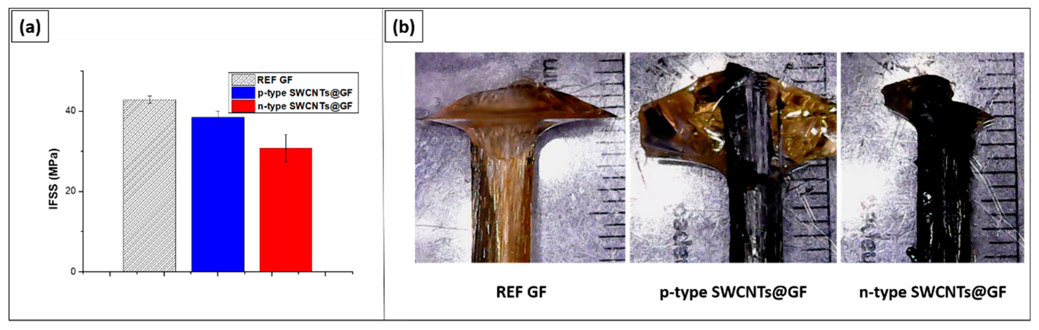
Fracture morphologies of the pulled-out tows obtained via optical microscopy reveal a cohesive type of failure in all cases, since epoxy material remained on the tow surface after the pull-out process. In general, the GF tow was covered by a cone of resin and as such it was detached from the matrix. In the case of the n-type tows, a mixed type of failure mode was observed, whereby fiber/matrix-to-matrix failure was also present. The fiber-to-matrix failure, whereby the GF tow was completely detached from the resin, was not observed in any of the tested specimens. As should be noted, the persistent presence of cohesive failure within the matrix suggests that measured values were an underestimate of the true IFSS. This was also suggested during the process of experimental optimization where it was observed that small embedded length and low values of pull out force correlated more with fiber to matrix failure than cohesive failure.
In conclusion, it can be assumed that the presence of surfactant for the dispersions of both SWCNTs inks affected negatively the IFSS when a commercial epoxy resin was used as a matrix. Further studies could be performed oriented to optimize the coating process and simultaneously assess the effect of the surfactant existence on the interfacial shear strength [
51,
52]. As is well known, a strong interface provides efficient stress transfer but promotes brittle failure, whereas a weaker may promote energy dissipation and thus improve toughness. Balancing these conflicting requirements by engineering composite interphases to improve optimal strength and toughness values remains a great challenge.

 ,
, 


