Review

Measurement of Head-Related Transfer Functions: A Review

Institute of Communications Technology, Gottfried Wilhelm Leibniz Universität Hannover, DE-30167 Hannover, Germany
*
Author to whom correspondence should be addressed.
Appl. Sci. 2020, 10(14), 5014; https://doi.org/10.3390/app10145014
Submission received: 2 June 2020 / Revised: 3 July 2020 / Accepted: 10 July 2020 / Published: 21 July 2020
(This article belongs to the Section Acoustics and Vibrations)

Abstract

:
A head-related transfer function (HRTF) describes an acoustic transfer function between a point sound source in the free-field and a defined position in the listener’s ear canal, and plays an essential role in creating immersive virtual acoustic environments (VAEs) reproduced over headphones or loudspeakers. HRTFs are highly individual, and depend on directions and distances (near-field HRTFs). However, the measurement of high-density HRTF datasets is usually time-consuming, especially for human subjects. Over the years, various novel measurement setups and methods have been proposed for the fast acquisition of individual HRTFs while maintaining high measurement accuracy. This review paper provides an overview of various HRTF measurement systems and some insights into trends in individual HRTF measurements.

Graphical Abstract

1. Introduction

A head-related transfer function (HRTF) describes an acoustic transfer function between a point sound source in the free-field (without room information) and a defined position in the listener’s ear canal [1,2]. The head-related impulse response (HRIR) is the time domain representation of the HRTF. Since all relevant acoustic cues to localize real sound sources are contained in HRTFs, i.e., interaural level differences (ILDs), interaural time differences (ITDs), and monaural spectral cues [3], HRTFs are commonly applied to synthesize virtual sound images reproduced over headphones or loudspeakers (binaural or transaural reproduction) [4,5,6,7].
HRTFs are unique to each person due to individual anatomy, especially the pinna geometry. The use of non-individual HRTFs to create virtual acoustic environments (VAEs) may degrade the listening experience, e.g., reduce localization accuracy and perceived externalization [8,9,10]. For dynamic binaural rendering applications, it is important that virtual sound sources can be created in any direction relative to the listener, and the VAE can track listeners’ head movements in real-time [11,12,13]. Furthermore, for six-degrees-of-freedom (6-DoF) binaural audio reproductions [14] and interactive virtual/augmented/mixed reality (VR/AR/MR) applications [15], the distance information of virtual sound images is required. In the case of far-field sound sources (the source–listener distance is typically larger than 1 m), the perception of sound distances is usually simulated by adjusting the sound level according to the inverse-square law, since far-field HRTFs are asymptotically distance-independent. In contrast, in the near-field (the source–listener distance is typically less than 1 m, proximal region), HRTFs vary noticeably as a function of distance [16]. Consequently, direction- and distance-dependent individual HRTFs are required to create immersive VAEs.
Measuring high-density HRTF datasets for each individual listener is usually a time-consuming task, especially when considering different source–listener distances. Several studies proposed to interpolate and extrapolate (distance or direction) sparse HRTF sets to obtain a high-density HRTF dataset [17,18,19,20,21,22,23,24,25,26]. Although these interpolation/extrapolation approaches can reduce the HRTF measurement points, the required number of measurements is still high [27,28]. Over the years, different measurement systems have been proposed for the fast acquisition of individual HRTFs. In addition to the acoustic measurement solution, other approaches, such as individualization/selection of HRTFs from non-individual HRTF datasets, calculation of HRTFs from scanned/simulated head models, can alternatively be applied to obtain personalized HRTFs. These solutions exceed the scope of this review article, and for more information please refer to [15,29,30,31,32,33,34].
There exist various HRTF measurement systems including measurement setups and methods. The latest summaries of HRTF measurement systems are given in [35,36]. Xie [35] provided a detailed introduction to HRTF measurement principles and several examples of measurement systems. Enzner et al. [36] presented some rapid measurement systems for recording far-field HRTFs and showed trends in acquisition of HRTFs, but focused mainly on continuous measurement methods which they proposed at that time. This article provides an overview of the state-of-the-art in HRTF measurement systems and some insights into the trends in individual HRTF measurements.
As shown in Figure 1, the rest of this paper is structured as follows. Section 2 describes the basic principle of HRTF measurements. Afterwards, various measurement setups for the acquisition of high-density HRTF datasets are outlined in Section 3. Depending on the measurement setups used, different fast HRTF measurement methods are reviewed in Section 4 and Section 5. Then, Section 6 presents some relevant post-processing steps/methods for the measured HRTF data to eliminate the influence of measurement setups/systems and environments. The measurement uncertainties, HRTF evaluation methods, HRTF storage formats, and considerations and trends in HRTF measurements are discussed in Section 7. Finally, a conclusion of this review paper is drawn in Section 8.

2. Principle of HRTF Measurements

This section provides an overview of HRTF measurement principles. Different measurement systems for the fast acquisition of direction- and distance-dependent HRTFs are given in Section 3, Section 4 and Section 5.

2.1. HRTF as a Linear Time Invariant (LTI) System

A HRTF represents a linear time invariant (LTI) system (an approximation under certain conditions) between an acoustic point sound source in the free-field and a defined position in the listener’s ear canal (static scenarios). Theoretically, all methods for identifying the transfer function of an LTI system can be applied to HRTF measurements.
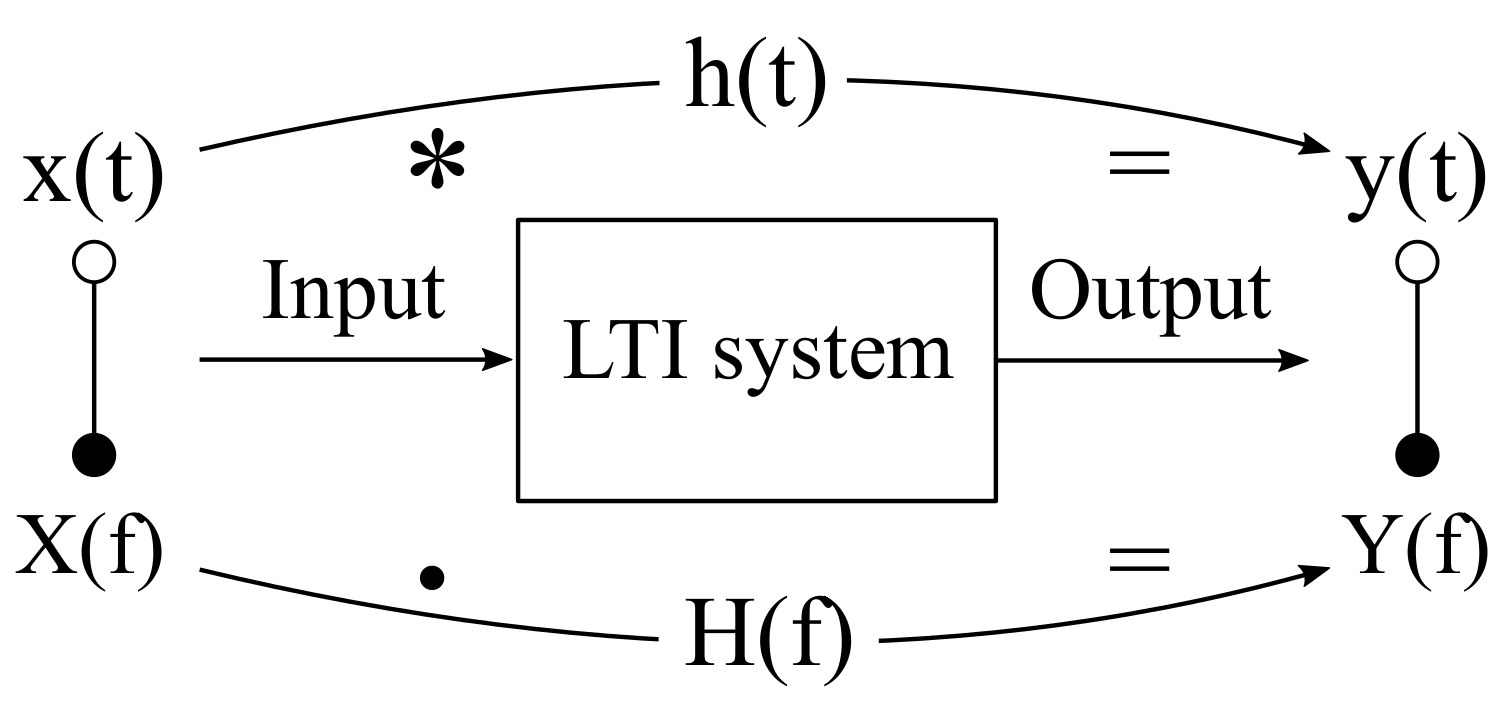
Figure 2 shows the basic principle of signal processing through an LTI system [6]. In the time domain, the output signal y ( t ) in response to the input signal x ( t ) is expressed as:
y ( t ) = x ( t ) h ( t ) = x ( τ ) h ( t τ ) d τ ,
where ∗ denotes the convolution operator, and h ( t ) represents the impulse response of the LTI system. Equivalently, in the frequency domain, the relationship between the input X ( f ) and the output signal Y ( f ) can be formulated as:
Y ( f ) = X ( f ) · H ( f ) ,
where H ( f ) is the transfer function of the LTI system. The signal transformation from the time to the frequency domain can be realized with the Fourier transformation (FT). Based on Equation (2), the transfer function of an LTI system under testing can easily be calculated from the excitation signal and the system response in the frequency domain:
H ( f ) = Y ( f ) X ( f ) .
The corresponding system impulse response, h ( t ) , can be obtained by applying the inverse Fourier transformation (IFT) to H ( f ) . In the digital domain, fast Fourier transformation (FFT) and its inverse (IFFT) are commonly used to efficiently convert discrete signals between time and frequency domains (the signal length should be a power of 2). Directly dividing the spectrum of the system response by the excitation signal (cyclic deconvolution) may cause aliasing errors (cyclic shifts in the time domain). Thus, prior to the division in the frequency domain, the excitation signal and the system response are zero padded to double their original lengths (or double their FFT length) to avoid the aliasing (linear deconvolution) [37,38]. Furthermore, to avoid the division by small values, a suitable regularization method should be considered [39]. Alternatively, h ( t ) can be obtained by convolving the system response with the inverse of the excitation signal ( x i n v ( t ) ) [40]:
h ( t ) = y ( t ) IFT 1 X ( f ) = y ( t ) x i n v ( t ) .
Except for this classical deconvolution method, several other approaches have been developed based on the properties of excitation signals to be used. As an example, the time-reversed filter and circular cross-correlation methods are particularly suitable for deconvolving some sweep signals and pseudo random sequences, respectively (see Section 2.2) [37,38,40,41].

2.2. Basic HRTF Measurement Methods

The HRTF measurement is typically performed in an anechoic chamber, which is used to simulate the free-field environment. In the early stage of acoustic research, analog methods were applied for measuring acoustic impulse responses, e.g., using the signal generator and level recorder, etc. [3,37,42,43]. Compared to the digital measurement techniques used today, the signal processing procedures are complex and the measurement accuracy is poor. Note that the drawbacks of analog measurement methods used in early studies are mainly due to the hardware and software used, some measurement methods themselves, such as sweep techniques, stepped-sine methods, are still often used today.
Figure 3 shows a basic HRTF acquisition setup based on digital measurement techniques [35]. A subject is equipped with a pair of in-ear microphones, and a sound source (loudspeaker) is placed at a defined position relative to the subject. An excitation signal is generated in a computer and reproduced via the loudspeaker after passing through a digital-to-analog converter (DAC) and a power amplifier. The emitted signals are picked up by in-ear microphones, then amplified, converted into the discrete form passing through an analog-to-digital converter (ADC), and delivered to the computer. The recorded ear signals and the excitation signal are then used to calculate the pair of HRTFs. After the measurement, the raw data should be further post-processed (see Section 6).
In principle, any signal containing energy at the frequencies of interest can be used as an excitation signal for the HRTF measurement. The signal energy should be high enough against the environmental noise (typically between 15 and 30 dBA) to ensure a sufficient signal-to-noise ratio (SNR) of the measurement result (typically above 60 dB) [35]. On the other hand, the energy of the excitation signal must be carefully limited according to the dynamic range of measurement devices, e.g., loudspeakers, power amplifiers, and in-ear microphones. Moreover, the nonlinear behavior of electro-acoustic systems should be considered in practice [37,38,44]. Assuming that the background noise is uncorrelated with signals, the SNR can be enhanced by increasing the excitation signal length. If the length can not be changed due to some special design requirements, repeating the measurement also leads to an improvement of SNRs. Theoretically, doubling the number of averages increases the SNR of the measurement result by 3 dB [37,38]. In the literature, various methods (excitation signals and the corresponding deconvolution methods) have been proposed to measure acoustic impulse responses, e.g., impulse excitation [3,45], stepped-sine signals [37,38], sweep signals [41,46], time delay spectrometry (TDS, an early measurement method using sweep signals) [46], maximum length sequence (MLS) [47,48,49,50,51], Golay code [52], inverse repeated sequence (IRS) [53,54], random noise signals [35], etc. Most of them have been systematically described in [35,37,38,55], and a comparative analysis of several important methods can be found in [37,40,44]. Instead of using deconvolution methods, acoustic impulse responses can be estimated recursively with adaptive filtering approaches, which are widely applied to identify unknown systems [56].
In addition to the “direct measurement method” as shown in Figure 3, Zotkin et al. [57] proposed a “reciprocity method” in which the speaker and microphone positions are exchanged according to the Helmholtz principle of reciprocity [58]. In the measurement, a pair of miniature loudspeakers is placed in the subject’s ears, and the microphones are located at the positions where HRTFs are to be measured. The main benefit of this method is that the HRTFs from different directions can be measured simultaneously (a microphone array is required). In the case of the HRTF measurement for a single position or only a few positions, there is no advantage by using this approach. Moreover, some practical issues need to be considered, e.g., the poor performance of miniature loudspeakers at low frequencies, low SNRs due to the limited playback level of excitation signals for physiological safety. Note that the main difference between the “direct measurement method” and the “reciprocity method” is the position of sound sources (speakers) and receivers (microphones). The way to derive HRTFs (deconvolution or adaptive filtering approaches) can be the same for both “methods”.
In the following, some important approaches for the HRTF measurement are described in detail, namely pseudo random sequences (MLS/IRS and Golay code), sweep signals (linear and exponential sweeps), and the adaptive filtering method.

2.2.1. HRTF Measurement with Pseudo Random Sequences

A pseudo random sequence is a deterministic discrete time sequence, which can be designed as a signal with an ideal power spectral density characteristic and a low crest factor (ratio between the peak and standard deviation of the signal). Various pseudo random sequences exist, like Legendre sequences [49], binaural Gold sequences [59], Kasami sequences [59], MLS/IRS [48,54], Golay codes [52], etc. The details of these sequences can be found in [55], and this section focuses on the MLS/IRS and Golay codes which are commonly applied for the acoustic measurement when using pseudo random signals.

MLS/IRS

MLS is a binary sequence that can be created by an L-stage linear feedback shift-register with a period length N = 2 L 1 (the case with “all zeros” sequence is not included) [48]. Figure 4 shows an example of such a shift-register which consists of L sequent registers and uses the Lth register state as the sequence output. Under the control of clock signals, the state of each register (0 or 1) moves step by step in one direction (in this case from left to right), and can be expressed as [35,55]:
a i ( n + 1 ) = a i 1 ( n ) , for i { 2 , 3 L } , a 1 ( n + 1 ) = c 1 a 1 ( n ) c 2 a 2 ( n ) c L 1 a L 1 ( n ) c L a L ( n ) ,
where n and n + 1 indicate the nth and n + 1 th clock pulses, respectively. The symbol ⊕ denotes the modulo 2 adder, and c i represents the feedback coefficient ( i { 1 , 2 , 3 , , L } ), which can either be 0 or 1 except for c L ( c L = 1). After the nth clock pulse, the output state can be represented as a L ( n ) = a 1 ( n L + 1 ) . A bipolar form ( s i { 1 , 1 } ) is often applied to create signal waveforms in practice, thus the binary sequence output is remapped to a bipolar sequence with s i = 1 2 a i . Taking the advantage that the circular auto-correlation of the MLS signal approaches an impulse function, the impulse response h ( n ) can be calculated by the circular cross-correlation of the recorded y ( n ) and the excitation signal x ( n ) [35,60]:
r x y ( n ) = x ( n ) y ( n ) = h ( n ) + 1 N ( N + 1 ) n = 0 N 1 h ( n ) 1 N n = 0 N 1 h ( n ) ,
where the second term of the equation can be neglected when using a long MLS. The third term is actually a direct current (DC) part of the impulse response, and must not be considered for an alternating current (AC) coupling system [35]. The fast Hadamard transformation (FHT) is usually applied for efficiently performing the circular cross-correlation process [55], and the length of the MLS signal should be large enough (longer than the system impulse response) to overcome the time-aliasing error caused by the circular cross-correlation operation [44]. The advantage of the MLS approach is the robustness against transient noises due to the uniform distribution of its energy over the measurement signal [60]. One disadvantage of the MLS approach is the low immunity against harmonic distortions in the measurement results caused by nonlinearities of measurement systems [61]. A straightforward solution to avoid the harmonic distortions is to reduce the playback level (at least 5–8 dB below full scale reported in [37]). In practice, an optimal reproduction level should be chosen as a compromise between maximizing the SNR and minimizing the distortions [44,62].
Dunn and Hawksford [54] modified the MLS signal and proposed an IRS method to attenuate the harmonic distortion levels. An IRS can be formed as:
IRS ( n ) = MLS ( n ) if n is even , n { 0 , 2 , 4 , 6 , , 2 N 2 } , MLS ( n ) if n is odd , n { 1 , 3 , 5 , 7 , , 2 N 1 } .
An IRS signal has a period of 2N, where N is the period of an MLS. After the deconvolution (circular cross-correlation) process, the impulse response h ( n ) , and its inverted version h ( n ) are located in the first (from 0 to N-1) and second half (from N to 2N) of the measured impulse response, respectively. Dunn and Hawksford [54] demonstrated that the IRS approach provides high immunity against even-order nonlinearities while maintaining the advantages of the MLS method. Based on the MLS/IRS, several methods have been proposed to further improve the robustness against background noises and nonlinearities [63,64] or to accelerate the deconvolution process [65].

Golay Codes

Golay codes [52] are a pair of complementary sequences, { a L , b L } , with a length of N = 2 L (L is the sequence order). The pair of complementary sequences is initialized for example as (L = 1): a 1 = { 1 , 1 } and b 1 = { 1 , 1 } . For L ≥ 2, the Golay codes are generated according to the following recursion rules [35,55]:
a L : Append b L 1 to a L 1
b L : Append − b L 1 to a L 1
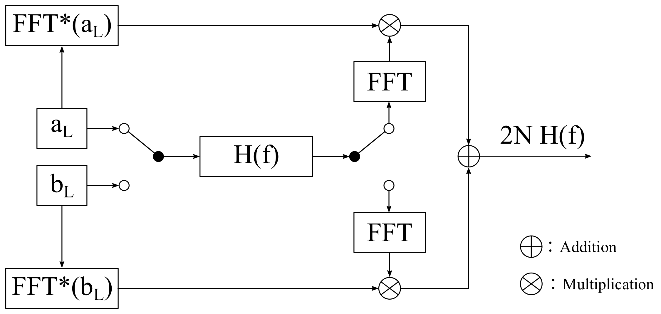
After L−1 recursive processes, a pair of Golay codes, { a L , b L } , with a length of 2 L is obtained. An important property of Golay codes is that the sum of the auto-correlations of the pair of complementary sequences is zero except at the origin (two-valued function) [66]. In the frequency domain, this property is expressed as:
FFT ( a L ) FFT ( a L ) + FFT ( b L ) FFT ( b L ) = 2 N ,
where FFT stands for the complex conjugates of FFT.
This property can be utilized for the measurement of the acoustic transfer function H ( f ) as shown in Figure 5: a L and b L are separately emitted from the loudspeaker, the recorded signal is transformed in the frequency domain using an N-point FFT, resulting in H ( f ) FFT ( a L ) and H ( f ) FFT ( b L ) . After that, the first part, H ( f ) FFT ( a L ) , and the second part, H ( f ) FFT ( b L ) , are multiplied by FFT ( a L ) and FFT ( b L ) , respectively. The resulting two parts are summed together to obtain H ( f ) by applying Equation (8):
H ( f ) = 1 2 N [ H ( f ) FFT ( a L ) FFT ( a L ) + H ( f ) FFT ( b L ) FFT ( b L ) ] .
After that, the system impulse response h ( n ) is calculated by applying the IFFT to H ( f ) . However, the two complementary sequences, { a L , b L } , must be excited sequentially (one after the other). For individual HRTF measurements, this approach is not robust to the time-variance effect caused by unconscious movements of subjects. In this sense, the MLS/IRS is preferable to Golay codes when measuring HRTFs for human subjects [35,67].

2.2.2. HRTF Measurement with Sweep Signals

A sweep signal, sometimes called “chirp” or “swept-sine”, is a continuous signal whose frequency continuously changes with time. After the study presented by Farina [41], who revealed some advantages by using sine sweep signals for identifying system nonlinearities, the use of the sweep method has become a popular way to measure acoustic impulse responses, such as room impulse responses, HRIRs, or electro-acoustical systems. As mentioned before, the use of sweep signals to measure acoustic systems has already been reported in early studies [46,68,69]. The reason why this approach was not successfully applied at that time is mainly due to the immature hardware and software technology used to perform measurements [70]. Different types of sweep signals can be found in the literature, such as linear sweep [46,71,72], exponential sweep [41,70], red-colored sweep [38,73], sweeplets [74], hyperbolic sweeps [75], and constant-SNR sweeps [76]. Among them, linear sweeps (some researchers call them time stretched pulses, TSP [71,72]) and exponential sweeps (sometimes called log sweeps or logarithmic sweeps) are two popular sweep types that are often used to measure acoustic impulse responses when using sweep signals.

Sweep Generation

Linear and exponential sweep signals can be generated in either the time or the frequency domain.
Sweep Generation in the Time Domain
In the time domain, a sweep signal with time-varying frequencies is represented as:
x ( t ) = A sin ( φ ( t ) ) , and f ( t ) = 1 2 π d φ ( t ) d t ,
where A is the amplitude of the sweep signal, φ ( t ) and f ( t ) represent the instantaneous phase and frequency, respectively. For a linearly varying frequency (linear sweep), from f 1 to f 2 within the time T, f ( t ) can be expressed as:
f ( t ) = f 1 + c t , with c = f 2 f 1 T .
The parameter c is derived by substituting the time instance t with T, and the frequency f ( t ) with f 2 . The instantaneous phase φ ( t ) is then calculated by integrating the frequency function over time, and the resulting linear sweep signal x ( t ) is expressed as:
x ( t ) = A s i n 2 π f 1 t + 2 π ( f 2 f 1 ) T t 2 2 .
For a exponentially varying frequency (exponential sweep), also from f 1 to f 2 within the time T, the instantaneous frequency f ( t ) can be expressed as:
f ( t ) = f 1 e c t , with c = ln f 2 f 1 T .
After integrating the frequency over time, the resulting instantaneous phase φ ( t ) is then used to calculate the exponential sweep signal x ( t ) based on Equation (10):
x ( t ) = A s i n 2 π f 1 T ln f 2 f 1 e t T ln f 2 f 1 1 .
Unfortunately, as reported in [37,38], spectral ripples may appear at the beginning and the end of desired frequencies caused by sudden on/off switching at the beginning and the end of sweep signals, leading to a degraded crest factor. This issue can be avoided by creating sweeps in the frequency domain, which means that the magnitude and phases/group delays are artificially synthesized and then transformed into the time domain to obtain the sweep signal via the IFFT.
Sweep Generation in the Frequency Domain
The magnitude spectrum is white (constant over frequencies) and pink (decreases with 3 dB/octave) for the linear and the exponential sweep, respectively. The phase can be calculated by integrating the group delay τ G ( f ) over frequencies. In the case of linear sweeps, τ G ( f ) is set by [40]:
τ G ( f ) = τ G ( 0 ) + c f , with c = τ G ( f s / 2 ) τ G ( 0 ) f s / 2 ,
where f s is the sampling rate. τ G ( 0 ) and τ G ( f s / 2 ) represent the desired group delays at the DC (f = 0 Hz) and Nyquist frequency (f = f s /2), respectively. Then, the phase is calculated as:
φ ( f ) = 2 π 0 f τ G ( λ ) d λ = 2 π τ G ( f s / 2 ) τ G ( 0 ) f s f 2 + τ G ( 0 ) f + φ ( f 0 ) ,
where φ ( f 0 ) is usually set to zero, τ G ( 0 ) and τ G ( f s / 2 ) are comprised between 0 and T. Note that the resulting phase at the Nyquist frequency should be zero or π /2 to satisfy the condition for spectra of real-time signals [38]. Müller and Massarani [37] introduced an offset for the calculated phase to guarantee this condition:
φ corrected ( f ) = φ ( f ) f f s / 2 φ ( f s / 2 ) .
The linear sweep in the time domain can be obtained by applying the IFFT to the corrected phase in combination with a constant magnitude spectrum. Moreover, Müller and Massarani [37] suggested to choose a FFT block length that is at least twice longer then the desired sweep length to avoid the “wrap around” effect [40].
For the exponential sweep signal, τ G ( f ) is defined as [40]:
τ G ( f ) = a + b ln ( f ) .
The parameters a and b can be calculated based on the start and end frequencies ( f 1 and f 2 ) and their desired group delays ( τ G ( f 1 ) and τ G ( f 2 ) ):
τ G ( f 1 ) = a + b ln ( f 1 ) , τ G ( f 2 ) = a + b ln ( f 2 ) .
In general, f 1 is set as the first frequency bin of the FFT and f 2 is set to the Nyquist frequency ( f s /2). Then, the corresponding phase can be calculated as:
φ ( f ) = 2 π f 0 f τ G ( λ ) d λ = 2 π f ( a + b ( ln ( f ) 1 ) ) f 0 ( a + b ( ln ( f 0 ) 1 ) ) + φ ( f 0 ) ,
where f 0 is a small non-zero value ( f 0 > 0), and the replacement of the lower limit of the integral by f 0 instead of zero is due to the asymptotic property of the ln function ( ln ( 0 ) ∞). The calculated phase should further be corrected by applying Equation (17). Different from the linear sweep, the magnitude of the exponential sweep X ( f ) decreases 3 dB/octave, which can be expressed as a linear function by using logarithmic magnitude and frequency scales:
20 log 10 | X ( f ) | = c + d log 10 ( f ) ,
where the coefficients c and d can be determined based on the start and end frequencies ( f 1 and f 2 ) and the slope of the linear function (− 3 dB/octave). After that, the exponential sweep signal in the time domain can be reconstructed by applying the IFFT to the synthesized spectrum.

Properties of Sweep Techniques

HRTFs can generally be derived based on the excitation signal and the recorded ear signals by applying the linear deconvolution method in the frequency domain. Alternatively, HRIRs can directly be obtained by convolving the recorded signals with the inverse of the excitation signal in the time domain, which is particularly suitable for the deconvolution of sweep signals [41]. The inverse filter of the linear sweep is exactly its time-reversed version due to the constant magnitude, while the inverse filter of the exponential sweep is its time-reversed version with a modified magnitude spectrum [41].
One major advantage of the sweep method is the discrimination of harmonic distortion products in the measured impulse response caused by nonlinearities of the measurement system. The group delay of the kth harmonic distortion that occurred in the impulse response can be expressed as [73]:
τ k , l i n ( f ) = f T f 2 f 1 1 1 k , τ k , e x p ( f ) = T ln ( f 2 / f 1 ) ln k ,
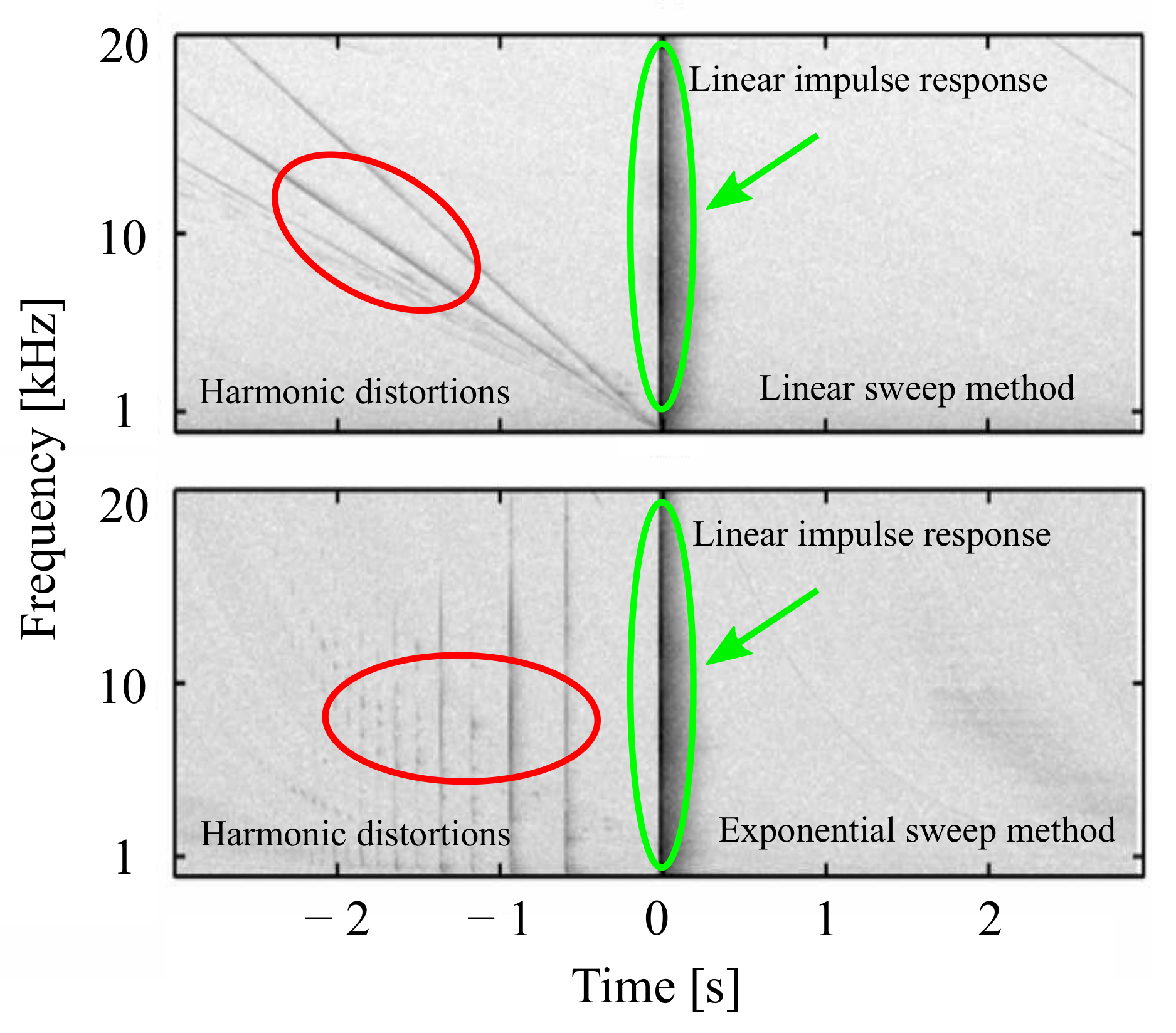
where τ k , l i n ( f ) and τ k , e x p ( f ) are the group delay of the kth harmonic in the system impulse response measured with linear and exponential sweeps, respectively. It can be observed that τ k , l i n ( f ) depends on frequencies, while τ k , e x p ( f ) is frequency independent (constant group delay). Figure 6 shows an example of measured system impulse responses by using linear (upper panel) and exponential (bottom panel) sweep signals [73]. The linear impulse responses and harmonic distortions are represented in the time-frequency domain (spectrogram). It can be observed that the linear sweep transforms harmonic distortions into down-sweeps (the frequency decreases with time) mostly before the linear impulse response begins. If exponential sweeps are used for the measurement, all harmonic distortions are packed in specific time intervals at negative times. Thus, compared to linear sweeps, the use of exponential sweep signals can better separate the linear impulse response and harmonic distortions of the system under test.
Several studies demonstrated that the use of sweep signals, especially the exponential sweep, is more robust against the time-variance effect than using pseudo random sequences [37,40,41]. One of the reasons is that the exponential sweep varies the frequency more slowly at low frequencies than at high frequencies, and the low-frequency signals are less sensitive to phase shifts [40]. Farina [70] proposed some further improvements of the exponential sweep method to enhance the SNR, suppress the pre-ringing at low frequencies, etc. Zhang et al. [77] mentioned that the environmental noise is mainly in low frequency ranges, and therefore proposed to use low-frequency emphasized sweep signals for acoustic measurements [78,79].

2.2.3. HRTF Measurement with Adaptive Filtering Methods

Adaptive filtering approaches have been widely applied in various acoustic applications, such as acoustic system identification [80], echo cancellation [81], active noise cancellation [82], and crosstalk cancellation [83]. The normalized least mean square (NLMS) method is one of the most popular adaptive filtering algorithms due to its high performance and ease of implementation [56]. Therefore, this section focuses on the use of NLMS-based adaptive filtering approaches to estimate static HRTFs.
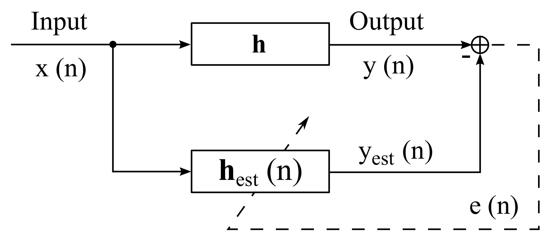
Figure 7 shows the block diagram for the system identification using adaptive filtering approaches in the time domain. h and h est ( n ) are vector representations of an unknown and the estimated system impulse response, respectively. The essential idea of this approach is to adapt h est ( n ) to h in a recursive form by minimizing the residual error e ( n ) between the estimated and the measured system output. In general, the NLMS method consists of the following steps [56,84]:
(1)
Calculation of the estimated output signal:
y est ( n ) = h est T ( n ) x ( n )
(2)
Calculation of the residual error between the measured and the estimated output signal:
e ( n ) = y ( n ) y est ( n )
(3)
Adaptation of the h est ( n ) based on the residual error and the input signal:
h est ( n + 1 ) = h est ( n ) + μ x ( n ) | | x ( n ) | | 2 2 + ϵ e ( n ) ,
where x ( n ) represents an input vector consisting of the most recent N samples of the input signal at the discrete time n. The regularization factor ϵ is used to avoid numerical problems when the dominator is close to zero. The step-size μ is a key parameter for the performance of the adaptive filtering process and should be carefully chosen as a trade-off between the tracking behavior and the noise rejection performance (0 < μ < 2). Alternatively, μ can be recursively adjusted according to estimation errors (variable step-size NLMS) [85,86].
Broadband signals such as pseudo random sequences, white noises, and perfect sequences [87,88] are generally employed as excitation signals to identify systems when using adaptive filtering techniques. Antweiler et al. [89] demonstrated that the perfect sweep, derived from the class of perfect sequences, is an optimal excitation signal for identifying acoustic systems (tested with the NLMS method). The use of perfect sweep signals can accelerate the convergence speed of the adaptation process and provide high robustness against nonlinearities of measurement systems. The perfect sweep is actually a linear sweep with periodical repetitions and can be generated in the frequency domain with a constant (white) magnitude spectrum and a linear group delay. Enzner [80] introduced the use of adaptive filtering methods for the HRTF measurement and showed the advantages to continuously capture multi-directional HRIRs (see Section 4).

2.3. Microphone Position and In-Ear Microphones

The HRTF measurement (“direct measurement method”) requires a pair of miniature microphones to capture audio signals in the ear canals. However, the measurement results depend on the microphone positions, as the sound pressure changes along the ear canal [45,90,91,92,93]. The choice of the microphone position for recording sound pressures in the ear canal varies in different studies, e.g., at the entrance of the ear canal [94,95,96], 2 mm inside the ear canal [45], 5–10 mm deep to the entrance of the ear canal [97], close to the eardrum (1–3 mm from the eardrum) [90,98,99], etc. Those measurement results are difficult to compare due to the non-uniform distribution of sound pressures in the ear canal. It is clear that almost all localization properties including the ear canal resonance can be taken into account when measuring the sound pressure near the eardrum. However, inserting the miniature microphones into the ear canal is unpleasant and may harm subjects with an incorrect operation. Alternatively, Hiipakka et al. [100] proposed a method to estimate the HRTF spectra at the eardrum with the pressure–velocity (PU) measurement at the ear canal entrance.
Several studies have investigated the need to record the excitation signal near the eardrum for the HRTF measurement [1,101,102]. Møller [1] modeled the sound transmission within the ear canal with a one-dimensional transmission line, which was valid up to 10 kHz by approximating the ear canal as a tube with a diameter of 8 mm, and considering it as a direction-independent part. Only the acoustic transfer path from a sound source in the free-field to the ear canal entrance was direction-dependent. Hammershøi and Møller [101] verified this concept with psychoacoustic experiments, and refined the entire acoustic transfer path from an acoustic point source to the eardrum into three parts: one direction-dependent part, i.e., from the sound source to the blocked entrance of the ear canal, and two direction-independent parts, i.e., the transmission from the blocked to open entrance of the ear canal, and the transmission along the ear canal. Thus, the localization cues contained in HRTFs can be well measured by placing the microphones at blocked entrances of the ear canals. Algazi et al. [102] further measured and evaluated HRTFs from various directions for blocked and open ear conditions, and the result was in agreement with the findings in [1,101], i.e., the direction-dependent characteristics of sound sources can be well captured by placing the microphones at entrances of blocked ears. The “blocked ear technique” is therefore generally applied in HRTF measurements for human subjects because of its convenience compared to the measurement in the ear canal.
There are many commercially available in-ear microphones for HRTF measurements and binaural recordings at the ear canal entrance or in the ear canal, e.g., B & K 4101 (Brüel & Kjær, Nærum, Denmark), DPA 4060 (DPA Microphones A/S, Alleroed, Denmark), MS-TFB-2 (The Sound Professionals, Hainesport, NJ, USA), MM-BSM-11 (Microphone Madness, Inc., Palm Coast, FL, USA), Soundman OKM II (Soundman e.K., Woltersdorf, Germany), MKE 2002 (Sennheiser, Wedemark, Germany), B & K 4182 (Brüel & Kjær, Nærum, Denmark), ER-7C Probe Microphone (Etymotic Research, Inc., Elk Grove Village, IL, USA). In addition, some researchers prefer to design their own miniature microphones by embedding microphone capsules (e.g., Knowles FG series, Sennheiser KE3/KE4) in custom-made ear molds or earplugs [103,104].
Some studies measured HRTFs with microphones placed in various hearing aids [64,105,106], and the measurement results are useful for hearing instrument research, evaluating spectral distortions caused by hearing aids, and generating virtual sounds for hearing aid users, etc. Artificial heads (or dummy heads, head-and-torso systems) such as KEMAR (GRAS Sound & Vibration A/S, Holte, Denmark), Neumann KU-100 (Georg Neumann GmbH, Berlin, Germany), HMS IV (HEAD acoustics GmbH, Herzogenrath, Germany), and B & K 4128 (Brüel & Kjær, Nærum, Denmark), are widely employed for measuring non-individual acoustic impulse responses and recording binaural sounds. Compared to human subjects, dummy heads show some advantages in the measurement, e.g., measurement errors due to unconscious movements or breathing can be avoided, measurement results are highly repeatable, and a long-term measurement is possible. Dummy heads are therefore suitable for comparing different HRTF measurement systems or methods.

2.4. Sound Sources

According to the definition in [1], a point sound source should be used for measuring HRTFs. Electro-acoustic devices, such as loudspeakers, are generally used as sound sources for measuring HRTFs. An ideal loudspeaker should have a flat frequency response, low nonlinearity, and omni-directional directivity (within the measurement region) across frequencies of interest. In practice, a compromise should be made, since no loudspeaker can fulfill all of these characteristics.
To ensure a flat frequency response, two or more drivers are usually working together in one loudspeaker, and each driver is responsible for reproducing sounds in one specific frequency range. For a two-way loudspeaker, the driver with a large size is used for reproducing sounds between low and mid frequencies, while the small-size driver is responsible for sounds between mid and high frequencies. A typical N-way loudspeaker with different radiation centers can not be considered as a point sound source. Alternatively, N-way coaxial loudspeakers or small single-driver speakers may be more suitable for approximating point sound sources, but sufficient performance at low frequencies can not be guaranteed [35]. The choice of the sound source may not be critical for measuring far-field HRTFs with a large distance, and many laboratories use commercially available two or three-way loudspeakers for far-field HRTF measurements because of their flat frequency responses (“direct measurement method”). Alternatively, some researchers build their own loudspeakers towards an optimal sound source for the measurement [107,108].
In the case of near-field HRTF measurements, the sound source is particularly important. The directivity of the sound source should be nearly omni-directional (approximation of the characteristic of an acoustic point source) at least within the main measurement region between the sound source and the subject’s head. Moreover, with a close distance, multiple reflections/scattering between subject and sound source may influence measurement results. This problem is more serious when measuring near-field HRTFs with multi-channel systems due to multiple reflections/scattering among sound sources [109]. Hence, a small-size sound source is required for the measurement of near-field HRTFs. In the literature, some sound sources have been proposed to approximate ideal point sound sources, e.g., a probe tube-type source, consisting of an electrodynamic horn driver and a 3 m-long section of Tygon tubing [16], a spark noise generated by an electrical discharge with a transformer and electrodes [110], a micro-dodecahedral loudspeaker with piezoelectric ceramic devices [111,112]. However, most of them have poor SNRs below 1 kHz. To improve the SNR at low frequencies, Hayakawa et al. [113] designed a micro-dodecahedral loudspeaker system consisting of electrodynamic speaker units. Moreover, Qu et al. [114] used a spark gap (Type BDMS1-040528) to measure near-field HRTFs, and the property of impulse signals generated by the spark gap was very close to a point sound source. However, this particular sound source is not often used in most acoustic laboratories. Yu et al. [115] numerically analyzed influences of the sound source size on near-field HRTFs caused by multiple reflections/scattering. The simulation results suggested that, in order to guarantee the spectral distortions within 1 dB at a source-subject distance of 0.2 m (or 0.15 m), the source radius should be smaller than 0.05 m (or 0.03 m). Otherwise, some absorption material around or on the source surface is required [109]. In addition to the special sound sources mentioned above, some researchers prefer to use custom-made loudspeakers (broadband drivers with specially designed enclosures) for near-field HRTF measurements [79,116,117].

3. Overview of HRTF Measurement Setups

Section 2 describes basic measurement principles for obtaining a pair of HRTFs. However, many binaural rendering applications require HRTF datasets covering different directions and even various distances. Such a massive dataset can be measured by repeating the methods described in Section 2 by changing the position of the loudspeaker or the listener until all desired measurement positions are covered, but it may take a lot of time to complete the measurement. Over the years, various HRTF measurement setups and methods have been proposed to speed up the measurement process.
The number and distribution of HRTF measurement points vary among different laboratories and publicly available datasets. Minnaar et al. [27] illustrated that the angular resolution of 8 ° is sufficient to avoid audible artifacts when applying interpolation, resulting in at least 1130 HRTF pairs to be measured. A lot of studies are interested in the HRTF representation in the spherical harmonic (SH) domain, taking advantage of the spatial continuity and orthonormality of SHs over the sphere. Such a representation shows the suitability for HRTF interpolation/extrapolation [20,21,22,23], binaural rendering [118], etc. Zhang et al. [28] compared various spatial sampling schemes (distributions of measurement points) and revealed that the IGLOO schema is the most suitable one when considering the SH transformation, and the required minimum number of HRTF pairs is 2304. Bates et al. [119] further proposed a sampling schema with the consideration of practical loudspeaker arrangements.
Most HRTF measurement systems are designed for capturing far-field HRTFs, which are distance-independent. In contrast, HRTFs are highly distance-dependent in the near-field. The HRTF spectra appear to be low-pass filtered as the sound source approaches the listener’s head. Moreover, the ILDs increase noticeably for lateral sound sources as the distance decreases, while the ITDs are almost the same at various distances [16]. For 6-DoF binaural rendering applications, distance-dependent HRTF datasets are required to synthesize realistic nearby virtual sound sources. Therefore, near-field HRTFs should not only be measured for different source directions but also for various distances (see examples in [79,114,117,120]), leading to a greater workload than the measurement of far-field HRTFs. The main differences between the far- and near-field measurements are the measurement distances and the sound sources used (see Section 2.4).
Independent of far- or near-field HRTFs, multi- and single-loudspeaker setups are commonly applied for the measurement, and each setup can be used to discretely or continuously measure HRTFs. This section provides an overview of the state-of-the-art in HRTF measurement setups and some special measurement systems.

3.1. Multi-Loudspeaker Setups

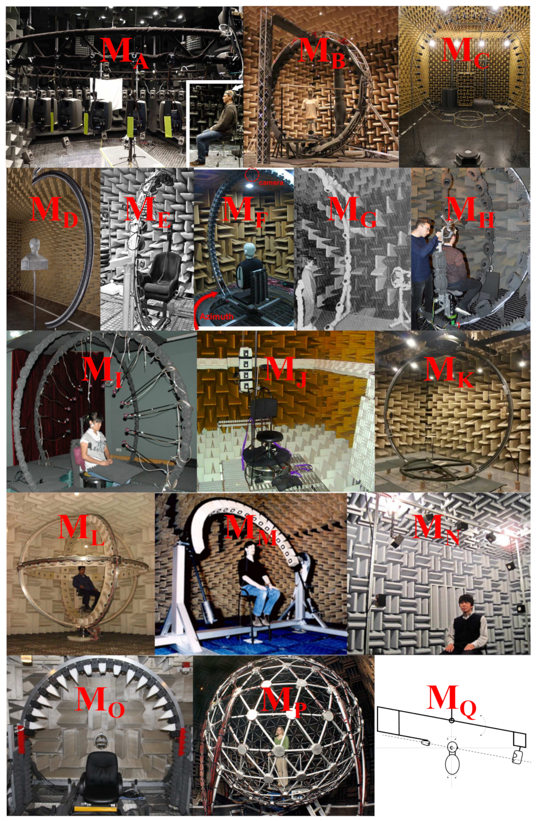
Figure 8 shows some examples of multi-loudspeaker-based HRTF measurement setups. The setups M A and M P contain multiple loudspeakers placed in a spatial or sphere layout. For the HRTF measurement, the subject should sit or stand in the measurement position, and the center of the subject’s head is coincident with the center of the loudspeaker arrangement. Since the loudspeaker positions may already cover all desired measurement directions, there is no need to ask the subject to turn the head or body into other orientations. To obtain HRTF datasets with a high spatial density, it is still necessary to change the the subject’s orientation.
The loudspeaker setups M B M I , M L M O are widely applied for the HRTF measurement, where the loudspeakers are mounted on a vertical arc, a horizontal arc, or a circular arc. In order to cover different measurement directions, either the loudspeaker array (see setups M F , M L , M M and M O ) or the subject (see setups M B M E , M G M I , and M N ) should rotate, where the rotation of subjects can be achieved by using a turnable chair or a turntable.
The setup M K is a two-arc-source-positioning (TASP) system consisting of two vertical arcs [129]. The arcs can freely rotate around the vertical axis, and two loudspeakers on arcs are allowed to move along the arcs to cover measurement points. In setups M J and M Q , loudspeakers are mounted on a pivoting arc and a boom arm, respectively. HRTFs for different azimuth angles are measured by rotating the subject with a turntable, while HRTFs for elevation angles are measured by controlling the loudspeaker positions using the pivoting arc and the boom arm. Note that, in the setup M Q , two loudspeakers are used to measure HRTFs for two different distances. Though this setup contains two loudspeakers, the loudspeaker numbers do not help to speed up the measurement procedure. It can be considered as a single-loudspeaker setup [116].
The loudspeaker setups M I and M Q (only the left loudspeaker in the M Q ) are specially applied for measuring near-field HRTFs. The setup M Q only allows for measuring near-field HRTFs with a single distance, while the setup M I enables the measurement of distance-dependent HRTFs. In the setup M I , multiple loudspeakers are mounted on a vertical locating loop with support rods. Various distances between the loudspeakers and the listener can be achieved by adjusting the length of support rods [127]. The details about loudspeakers in setups M I and M Q can be found in [116,127].

3.2. Single-Loudspeaker Setups

Compared to multi-loudspeaker settings, single-loudspeaker setups can not rely on the number of loudspeakers to dramatically speed up the measurement process. Hence, these setups are often applied for measuring high-density HRTF datasets of dummy heads, when the measurement time is not a critical issue. In the case of measurements for human subjects, advanced algorithms or methods are required to reduce the measurement time.
Figure 9 shows several single-loudspeaker-based HRTF measurement setups. As shown in the setup S D , a loudspeaker is placed at a fixed position and a dummy head is placed on a turntable. A set of HRTFs for different azimuth angles (1D HRTFs) can be measured by rotating the dummy head using the turntable. Except for the setup S D , other setups in Figure 9 are able to measure HRTFs on both azimuth and elevation planes (2D HRTFs). With setups S B , S C , and S E , different 2D measurement positions are covered by rotating the dummy head/subject with a turntable and changing the loudspeaker position. In the setup S F or S G , a loudspeaker is mounted on a traverse arm and can be placed in any desired measurement position on the azimuth and elevation plane. By this means, the subject does not need to rotate during the HRTF measurement. The setup S A shows another possibility, where a dummy head (KU-100, without torso) is mounted on a custom bracket, and a loudspeaker is placed at a fixed position. Through the control of the bracket, the dummy head can perform a 2D rotation to cover different measurement positions. A similar setup can be found in [135], where a self-designed head-and-torso-system has multiple degrees of freedom that allow the head to rotate horizontally and tilt vertically. The single-loudspeaker setups can simply be applied for measuring distance-dependent HRTFs: after the 2D HRTF measurement with a fixed source–listener distance, the sound source (setup S B ) or the dummy head (setups S A and S D ) move to the next desired position for measuring 2D HRTFs with that distance. This procedure is repeated until all desired source–listener distances are covered.
Setups S H S K show novel measurement modes particularly designed for the fast HRTF measurement of human subjects. A loudspeaker is placed at a fixed position and continuously emits the excitation signal, while the subject is asked to rotate her/his head to cover different measurement directions. The head rotation is recorded using a head tracker device during the measurement. In addition, the movement pattern and desired measurement points are displayed on a video monitor (see the setup S J ) or a head-mounted display (HMD, see setups S I and S K ) to prompt the subject to cover unvisited measurement positions. The excitation signal, recorded ear signals and the orientation data, are synchronized and further used to calculate the HRTF from each measurement direction. AR/MR headsets can not only record the head orientation, but also detect the source–listener distance with integrated depth cameras. Hence, it is also possible to fast measure distance-dependent HRTFs (3D HRTFs) by using AR/MR headsets (see Section 5).

3.3. Multi-Microphone Setups

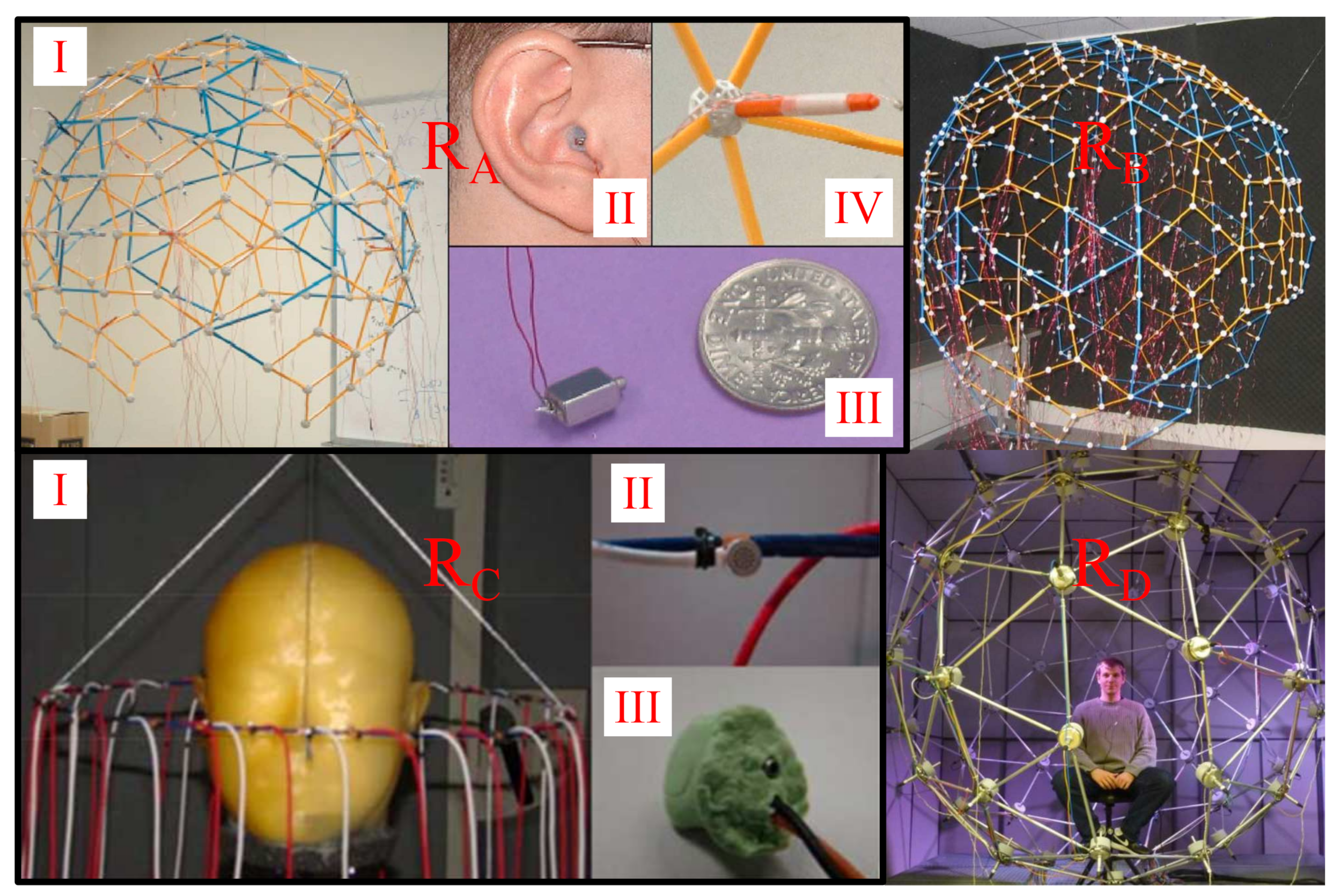
Figure 10 shows several HRTF measurement setups based on the “reciprocity method”, where multiple microphones are placed in a sphere layout (see setups R A , R B and R D ) or on a circular arc (see the setup R C ). Zotkin et al. [57] first introduced the “reciprocity method” to simultaneously measure HRTFs from different directions by using a microphone array as shown in part I of R A . One node of the microphone array can be seen in part IV of R A . In HRTF measurements, the microphone array surrounds the subject and a pair of miniature loudspeakers is placed in subject’s ears (see parts II and III of R A ). Excitation signals are reproduced via the pair of miniature speakers (left and right ear loudspeakers are excited in sequence), and the HRTFs from all microphone directions can be measured simultaneously. Setups R B and R D are similar to the setup R A , only the microphone types, the number and distribution of microphones are different. The setup R C is designed to measure near-field HRTFs on the horizontal plane, where multiple microphones are placed on a circular arc with a radius of 0.2 m around a dummy head (see part I of R C ). The microphones and miniature loudspeakers used can be seen in parts II and III of R C . Based on the “reciprocity method”, HRTFs from multiple directions are able to be measured within a few seconds. Additionally, the inter-equipment reflections are lower than in multi-loudspeaker setups because of the small-size microphones. However, due to the poor performance of the miniature loudspeakers at low frequencies and the limited playback level of excitation signals, most acoustic laboratories prefer to use “direct measurement method” to measure HRTFs.

3.4. Setups for HRTF Measurements in Non-Anechoic Environments

The HRTF measurement is normally performed in an anechoic and low-noise environment, such as an anechoic chamber, to avoid noticeable reflections and ambient noises during the measurement. For some reasons, e.g., lack of anechoic chambers, avoidance of long-term measurements on human subjects in anechoic environments, some studies measured HRTFs in non-anechoic but controlled acoustic environments, e.g., listening rooms [127,146,147,148], and some studies even performed measurements in ordinary rooms [149,150,151,152].
A typical method for eliminating reflections is to truncate the measured impulse responses with a window function in either the time [149,150,151] or the frequency domain [153] (see Section 6.1). As an alternative, Takane [152] represented the measured impulse responses with spatial principal components analysis (SPCA), and truncated the weight coefficients of principal components to remove reflections. Regardless of the excitation signal used, a common way to suppress the background noise in the measurement results is to repeat the measurement several times (or use repeated excitation signals) [149,150]. However, the difficulty in eliminating reflections and background noises depends on the acoustics of the measurement environment.
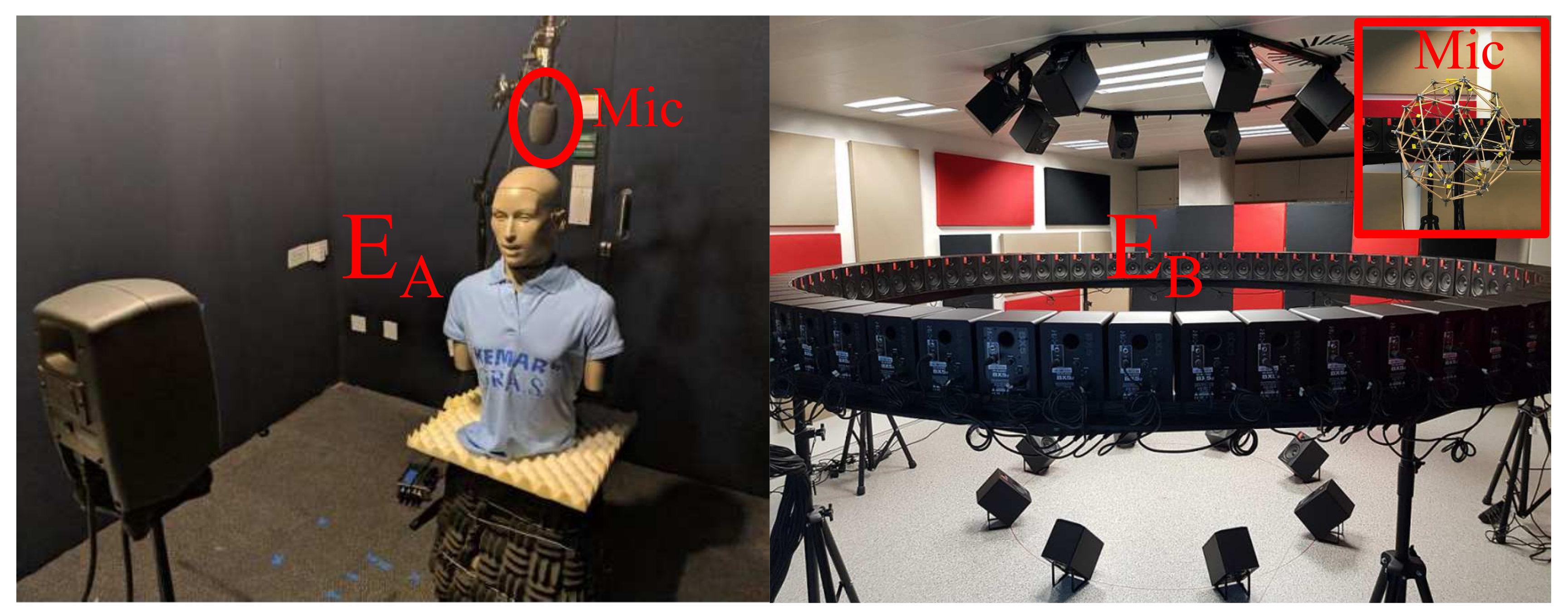
Two recent preliminary studies proposed novel concepts to suppress the background noise [154] and reflections [155] in the measurement results by analyzing acoustics of the environment with additional microphones (see Figure 11). He et al. [154] proposed to use an ambisonic microphone (Sennheiser AMBEO, above the dummy head in the setup E A ) to capture the sound field for measuring HRIRs. The existing sound field in the current room was recorded by the ambisonic microphone and further used to obtain the sound source signal, the ambisonic energy, the diffuseness, and the source direction. For each desired measurement direction, HRTFs could be calculated with the division of recorded ear signals by the sound source signal in the frequency domain (deconvolution method, see Section 2.1) when the diffuseness was minimum, the ambisonic energy was highest, or the ear signal energy was highest. Unfortunately that study presented only some simulation results. A similar approach can be found in [156], where the acoustic signal was recorded by a mono microphone and further used as a reference signal for the deconvolution process. Both studies show the possibility to use passively recorded natural acoustic sounds as excitation signals instead of actively emitting measurement signals, but the frequency range of measured HRIRs depends on the stimuli recorded. The major difference between these two studies is the microphone used, which leads to different possibilities in the choice of time frames for the deconvolution process.
Lopez et al. [155] proposed a method to cancel reflections in the measurement result by analyzing the reflection pattern prior to the HRTF measurement. The right panel in Figure 11 (setup E B ) shows the loudspeaker setup for measuring HRTFs in an ordinary room, consisting of 72 loudspeakers arranged on a circular array on the horizontal plane (the height of listener’s ears), and two circular arrays each with eight loudspeakers suspended from the ceiling and placed on the floor, respectively. Prior to the HRTF measurement, a custom-made spherical microphone array was placed in the middle of the loudspeaker setup where the listener would be, to measure impulse responses from loudspeakers to microphone arrays. Each impulse response measured was decomposed in different directions using the plane wave decomposition (PWD) method to detect the reflection pattern. After that, the subject stood in the same position as the microphone array for measuring HRTFs from different loudspeaker directions. The knowledge of reflection patterns was then used to suppress the reflections contained in measured HRIRs at low frequencies, while the reflections at high frequencies were removed using a window function. In the current stage, only the echo detection stage has been presented [155].

4. Multi-Loudspeaker-Based Fast HRTF Measurement Methods

Increasing the number of sound sources is an efficient way to reduce the measurement time. Multi-loudspeaker-based systems are mainly considered for accelerating HRTF measurements on the horizontal and elevation planes with a fixed source–listener distance (2D HRTFs). The setup M I in Figure 8 shows a possible solution to flexibly measure distance-dependent 2D HRTFs (3D HRTFs) with length-adjustable support rods. Regarding the measurement method itself, there is no major difference between 2D and 3D HRTF measurements, and the 3D HRTF measurement can be considered as multiple 2D HRTF measurements with various source–listener distances.
To improve readability, the description of various methods assumes that the loudspeakers are arranged on a vertical arc and the subject rotates with a turntable, similar to the setup M D as shown in Figure 8. However, all principles also hold for the rotation of loudspeaker systems, and these methods are valid for other similar setups as well. Two measurement mechanisms are generally applied to measure HRTFs, i.e., step-wise (stop & go) and continuous measurement mechanisms. With the step-wise mechanism, the subject is orientated to an azimuth angle and the HRTFs for different elevation angles (loudspeaker positions) can be quickly measured. Then, the subject turns to the next desired azimuth angle, and the same measurement is performed again. This procedure is repeated until all desired measurement directions are covered. When measuring HRTFs with the continuous measurement mechanism, the subject rotates continuously while the loudspeakers reproduce the excitation signal. In the following, an overview of fast HRTF measurement methods with these two mechanisms is given.

4.1. Step-Wise Measurements

In the case of the step-wise mechanism, the measurement methods developed mainly focus on reducing the time to measure HRTFs from different loudspeaker directions with a fixed azimuth orientation.

4.1.1. Multiple Exponential Sweep Method (MESM)

As stated earlier (see Section 2), the whole HRTF measurement system can be regarded as a weakly nonlinear system due to the nonlinear behavior of the measurement equipment (e.g., loudspeakers). The exponential sweep signal is an optimal choice for measuring such a system, since the harmonic distortions and the linear impulse response of the system can clearly be separated after the linear deconvolution process. In general, exponential sweep signals should be played back sequentially from different loudspeakers to measure HRTFs from corresponding directions. Majdak et al. [157] proposed a multiple exponential sweep method (MESM) consisting of interleaving and overlapping mechanisms to accelerate the measurement procedure and was further optimized by Dietrich et al. [158]. This method allows multiple loudspeakers to play back sweep signals almost simultaneously.

Interleaving and Overlapping Mechanisms

One mechanism of the MESM method is the interleaving, which utilizes the time interval between the linear impulse response and the 2nd order harmonic distortion of the measured system impulse response. Multi-channel systems are excited by exponential sweeps with a short time delay relative to each other, and, after the deconvolution process, a group of linear impulse responses of identified systems are placed between the beginning of the linear impulse response and the end of the 2nd order harmonic distortion of the last system [73].
The other strategy of the MESM method is to excite the exponential sweep for the subsequent system before the end of the previous sweep signal (overlapping). If the highest harmonic distortion of the system response does not disturb the measurement result of the previous system, the sweep signals can overlap in the time domain.
The combination of these two mechanisms formed the MESM. To identify N loudspeaker systems, M systems can be treated under the interleaving mechanism and the resulting N/M groups are overlapped between each other. A series of impulse responses over time can be calculated after the linear deconvolution, and the linear impulse response of each system can simply be extracted by applying a time window. Some parameters such as the length of the linear impulse response and the 2nd order harmonic distortion, and the order of the highest harmonic distortion should be pre-determined by a reference measurement prior to the formal measurement. These parameters are then used to optimize the total MESM measurement time towards either the minimal measurement time or the maximal SNR of the measurement results [157].

Optimized MESM

Weinzierl et al. [73] proposed a generalized multiple sweep method with spectrally adapted sweeps. The comparison results showed that the proposed method outperforms the original MESM for the measurement of long acoustic impulse responses (reverberation time > 2 s), while the original MESM becomes beneficial when measuring short impulse responses (reverberation time < 0.1 s).
Dietrich et al. [158] optimized the MESM method by using a generalized overlapping strategy instead of using overlapping and interleaving mechanisms. The measured raw HRIRs contain not only the direct sound components but also reflections that should be eliminated. Even if the measurements are performed in anechoic chambers, some reflections from measurement facilities can still be observed. Thus, only the direct sound part should be protected against the interferences by harmonic distortions and reflections when applying overlapping methods, not the whole impulse response. In contrast to the overlapping method proposed in [157], where the harmonic distortions are placed between linear impulse responses of overlapped groups, Dietrich et al. [158] introduced an avoid zone around the direct sound part, and the harmonic distortions are allowed to be placed within the linear impulse response part except for the avoid zone. Simulation results presented in [158] confirmed a reduction of the total measurement time compared to the original MSEM proposed in [157].

4.2. Continuous Measurements

Some methods have been developed for continuously measuring HRTFs assuming that HRTF is a continuous function of spatial directions [35]. This mechanism requires the subject to rotate continuously while the loudspeakers play back excitation signals. Ajdler et al. [159] proposed a theoretical method for capturing HRTFs with a rotating subject (moving microphones) and a fixed sound source. The HRTF for any azimuth angle can be reconstructed in the spatio-temporal frequency domain by applying the projection-slice theorem within only 0.66 s. However, it is only a theoretical measurement setup, practical measurements have not been performed and verified. Fukudome et al. [160] continuously measured HRTFs on the horizontal plane with a rotating subject and a fixed loudspeaker by applying the MLS method. The HRIRs for different azimuth angles were calculated by the cross-correlation method within one MLS period. Pulkki et al. [140] measured HRTFs with a continuously moving loudspeaker. The loudspeaker moved slowly (2°/s) around the subject with a fixed elevation angle and repeatedly emitted exponential sweep signals. The HRIRs were calculated by applying the linear deconvolution method within one period of the sweep signal. The measurement methods in [140,160] are actually based on the deconvolution techniques commonly used to measure static HRTFs (see Section 2). For these two measurement systems, the length of the excitation signal and the rotational speed of the subject/loudspeaker should carefully be chosen to ensure the relative changes in azimuth between the subject and the loudspeaker can be neglected within one period of the signal.
Richter et al. [161] proposed a fast measurement method with a rotating subject while the loudspeakers play back exponential sweeps under the MESM mechanism. This method extended the step-wise MESM approach and substantially reduced the measurement time. In addition to the continuous MESM approach, adaptive filtering algorithms are suitable for continuously recording multi-directional HRIRs based on the method described in Section 2.2.3 [80,162]. In the following, these two main continuous measurement approaches are briefly described, namely the continuous MESM and time-varying adaptive filtering method.

4.2.1. Continuous MESM

In contrast to the step-wise mechanism, Richter and Fels [123] proposed a method in which a subject rotates continuously using a turntable while loudspeakers play back exponential sweeps. The sweep signals are consecutively played back over loudspeakers with a certain delay relative to each other in an overlapped form [158]. After the last loudspeaker starts playing signals, the first loudspeaker should be restarted with an overlap. This means that the exponential sweep is played back repeatedly via each speaker while the subject rotates continuously. The total measurement duration is clearly reduced compared to the step-wise MESM approach because of the repositioning time saved at each azimuth angle.
The influence of a rotating subject on the frequency shift (Doppler effect) and the changes in measurement positions have to be taken into account, which may affect the quality of measurement results. Richter and Fels [123] demonstrated that the possible frequency shift caused by the rotation of a human subject is clearly lower than the just noticeable difference (JND) by assuming a fast rotational speed of 15°/s. Thus, the Doppler effect can be neglected if HRTFs are continuously measured with a typical rotational speed. In the case of the step-wise measurement, the HRTFs obtained from different loudspeaker directions have the same azimuth angle at each step. For the continuous measurement system, the azimuth angle changes continuously when the subject rotates during the measurement. Moreover, the changes in the azimuth angle are frequency-dependent since the excitation signal (exponential sweep) varies its instantaneous frequency with time. Richter and Fels [123] corrected the frequency-dependent offsets by the interpolation of measured HRTFs in the SH domain. In general, the measurement accuracy decreases with the increasing rotational speed. With a rotational speed of 3.8°/s, there was almost no audible difference to the step-wise measurement system [123,161].

4.2.2. Time-Varying Adaptive Filtering

Enzner [80] introduced an adaptive filtering method for continuously recording HRTFs on the horizontal plane with a fixed loudspeaker. The measurement setup can be assumed as S E in Figure 9. A subject equipped with a pair of in-ear microphones rotates continuously at a constant speed, while a loudspeaker plays back excitation signals at a fixed position. Assuming that the rotating HRIR is a time-varying linear system, the recorded ear signal y ( n ) at the discrete time n can be described as (neglecting the subscripts denoting the left and right ears):
y ( n ) = h T ( φ n ) x ( n ) + v ( n )
where φ n is an azimuth angle at the discrete time n, and v ( n ) describes the measurement noise. h ( φ n ) represents the HRIR for the azimuth angle of φ n in a vector form. x ( n ) is an input vector consisting of the most recent N samples of the excitation signal, where N is usually the same as the HRIR length. In this model, each time index corresponds to an azimuth angle of φ n . It should be noted that this model is valid under the assumption that the time of system changes is larger than the HRIR length [80]. By applying the NLMS recursive equation, the HRIR at the discrete time n + 1 can be predicted as:
e ( n ) = y ( n ) h est T ( φ n ) x ( n ) , h est ( φ n + 1 ) = h est ( φ n ) + μ x ( n ) | | x ( n ) | | 2 2 + ϵ e ( n ) ,
where e ( n ) represents the residual error between the estimated and the recorded ear signals at the discrete time n. This adaptation process can alternatively be implemented in the frequency domain [163]. Enzner [162] further extended the 1D HRTF estimation approach to measure HRTFs on both horizontal and elevation planes with multi-loudspeaker setups. Different from the method used in [161], the loudspeakers on the elevation plane can simultaneously play back excitation signals, while the subject continuously rotates. The measurement signals reproduced via loudspeakers must be independent of each other, which is an important condition for the simultaneous and unique identification of HRIRs from various directions. At the discrete time n + 1, the HRIRs for each elevation plane can be expressed as:
e ( n ) = y ( n ) θ v h est , θ v T ( φ n ) x θ v ( n ) , h est , θ v ( φ n + 1 ) = h est , θ v ( φ n ) + μ x θ v ( n ) θ v | | x θ v ( n ) | | 2 2 + ϵ e ( n ) ,
where the subscript θ v denotes different loudspeaker positions corresponding to discrete elevation angles of HRIRs. The excitation signal from each elevation angle (loudspeaker direction) is normalized with a common summing term, θ v | | x θ v ( n ) | | 2 2 , and the same residual error is applied to update HRIRs for different elevation angles [162]. Enzner et al. [36] verified the system with different loudspeaker numbers and rotational speeds. The measurement accuracy was represented by the error signal attenuation (ESA) with ESA = 10 log 10 ( σ e 2 / σ y 2 ) , where σ e 2 and σ y 2 denote the variance of error and recorded signals, respectively [36]. In that study, the white noise was used as the excitation signal for the measurement. Overall, the ESA reduces (measurement accuracy increases) with the decreasing rotational speed and number of loudspeakers. For the revolution time of larger than 60 s, the measurement accuracy is almost constant with the increasing rotational speed, and the dependence between the measurement accuracy and the loudspeaker numbers becomes small [36].
To further improve the measurement accuracy, perfect sweeps can be applied as the excitation signal (see Section 2.2.3). For L loudspeakers, a perfect sweep with a period of N × L is supplied to the first loudspeaker, then the subsequent loudspeakers are excited with the N sample shifted signal provided to the previous loudspeaker, where N is the HRIR length. Experimental results show a substantial improvement of the measurement accuracy by using perfect sweeps as the excitation signal compared to the use of white noises [36,89]. Kanai et al. [164] proposed a similar approach to simultaneously estimate HRTFs from multiple loudspeaker directions, where the loudspeakers were positioned on a horizontal arc around the subject. In that study, the phase-shifted MLS sequences were used as excitation signals and the estimation error was interactively reduced by using the prediction error method (PEM).

5. Single-Loudspeaker-Based Fast HRTF Measurement Methods

Since only one loudspeaker is present, the step-wise mechanism can take a lot of time for measuring high-density HRTF datasets. This measurement mechanism is generally applied to measure HRTFs of dummy heads if the measurement time is not a critical problem. In order to accelerate the measurement process, the continuous mechanism is considered.
As described in Section 4.2, the methods proposed in [80,140,160] are able to be used for continuously capturing 1D HRTFs (usually on the azimuth plane) either with a rotating subject (setup S E in Figure 9) or a rotating loudspeaker (setup S G in Figure 9) by using adaptive filtering algorithms [80] or conventional deconvolution approaches [140,160]. To obtain HRTFs on both the azimuth and elevation planes (2D HRTFs), the 1D HRTF measurement process should be repeated with different loudspeaker positions (elevation angles) until all desired measurement points are covered [140]. This measurement mechanism can be regarded as a semi-continuous mechanism, since HRTFs are continuously measured only on the horizontal plane.
Some researchers proposed a measurement system to continuously estimate 2D individual HRTFs by actively performing head movements [141,142,165,166,167,168,169]. The setup S J in Figure 9 can be regarded as an example hardware configuration for the continuous measurement of 2D HRTFs. A loudspeaker is positioned in front of a subject, who sits on a chair and is equipped with a pair of in-ear microphones. In addition, a head tracker device (inertial sensor) is placed on the subject’s head with a headband. During the measurement, the excitation signal (white noises or perfect sweeps) is played back via the loudspeaker and the subject is asked to rotate the head to cover different measurement directions. The acoustic signals ( y ( n ) ) and the orientation data ( φ n , θ n ) are recorded by in-ear microphones and the head tracker device, respectively. The adaptation of HRIRs can be performed either offline [142,167,168] or in real time [120,169] with the NLMS algorithm:
e ( n ) = y ( n ) h est T ( φ n , θ n ) x ( n ) , h est ( φ n + 1 , θ n + 1 ) = h est ( φ n , θ n ) + μ x ( n ) | | x ( n ) | | 2 2 + ϵ e ( n ) .
It is possible that some measurement points are revisited many times when performing head movements. Hence, Ranjan et al. [165] optimized the NLMS method to separately adapt the HRIRs at new and already measured points to speed up the convergence speed of the adaptation process. Besides the use of adaptive filtering algorithms, classic deconvolution methods combined with periodic excitation signals can also be used to measure HRIRs [140,160,170].
Li and Peissig [142] used a video monitor to display the head movement pattern, visited and unvisited measurement positions to prompt test persons to cover desired measurement directions (see S J in Figure 9). However, subjects can not constantly see the information when performing head movements (intermittent feedback [168]). To solve this issue, some researchers developed HRTF measurement systems based on VR/AR/MR HMDs (see S I and S K in Figure 9) that allow subjects to constantly see the information provided by HMDs during HRTF measurements (concurrent feedback [168]) [120,166,168,169]. In addition, the inertial sensors integrated in the VR/AR/MR headsets can be used to record head orientation data. Objective and subjective evaluation results showed that the HRTFs measured with these dynamic measurement systems are comparable to those measured with conventional static systems [167]. Instead of using inertial sensors [142,166,168], VR/AR/MR headsets [120,166,168,169], and cameras [170], some researchers proposed to acoustically track head movements based on the recorded ears signals and the knowledge of speaker positions [150], or by analyzing recorded signals with an additional microphone array [171].
The mobile systems described above show the potential for the fast acquisition of individual 2D HRTFs with only a few measurement devices. There are still some challenges to be considered, e.g., the synchronization between the orientation data and microphone signals, uncontrollable head-above-torso orientations (HATOs) during the measurement, influences of the variable rotational speeds, and the HMD on the accuracy of HRTFs [120,167,172,173].
As mentioned in Section 3, except for several special designs such as the setup M I in Figure 8, multi-loudspeaker systems are commonly designed for measuring HRTFs with a fixed distance. With a single loudspeaker, it is a time-consuming task for measuring HRTF datasets with a dense spatial resolution and various distances. Recently, Li et al. [120] developed a MR-based mobile measurement system (see setup S K in Figure 9) for continuously measuring distance-dependent multi-directional HRTFs (3D HRTFs). The MR device is used to detect the head orientation, the source–listener distance, and display movement pattern and measurement points to subjects. Unlike 2D HRTF measurements, the subject is not only asked to rotate her/his head but also to move towards or away from the loudspeaker. If the current source–listener distance is one of the desired measurement distances (an appropriate tolerance of the distance should be defined), some virtual 2D points representing measurement directions are visible through the HMD, and the subject should rotate her/his head to cover these measurement directions. At the same time, HRIRs are adaptively calculated using the NLMS method in real-time, and the quality (ESA) of each estimated HRTF is provided to the subject. If the current distance is not one of the desired distances, the measurement points (virtual 2D points) are not visible through the HMD. Li et al. [120] illustrated that the acoustical influence of the MR device (Microsoft HoloLens) on the binaural cues are overall small, but for some lateral directions the distortions are slightly larger than JNDs. There are still several open issues that should be addressed especially for measuring near-field HRTFs, e.g., the property of the sound source, the accuracy of the estimated distances. Nevertheless, this method provides a novel solution towards fast measuring 3D individual HRTFs with a single loudspeaker.

6. Post-Processing of Measured HRTFs

The raw HRTFs should be post-processed to remove the reflections, extend the low-frequency components, and compensate for influences of measurement systems. Note that the order of post-processing processes varies in the literature, and some processes may be performed several times. Moreover, some studies proposed to remove perceptually irrelevant components in HRTFs [106], and correct measurement errors caused by the equipment misalignment [137] and temperature fluctuations [174]. The important post-processing steps/methods are described below.

6.1. Windowing

To eliminate reflections, the measured HRTFs should be carefully truncated. In general, the truncation is done in the time domain by applying a window function, e.g., half Hann-window. Windowing may lead to a loss of information at low frequencies, and the cut-off frequency depends on the window length. The low-frequency components can be reconstructed by using the methods described in Section 6.3. Several studies proposed to truncate the impulse responses by applying a frequency-dependent window [153,175,176]. If the reflections are caused by the measurement equipment or some small-size objects, the energy of these reflections is mainly at mid and high frequencies. In this case, the impulse response at mid and high frequencies needs to be truncated while the low-frequency component can be retained [153]. The onset delays in HRIRs caused by the system latency or the distance between the sound source and the subject can be appropriately truncated, and a fade-in window is commonly applied before the peaks of HRIRs to avoid discontinuities [126,174]. The final length of HRIRs is different in each study and varies from 2.5 to 20 ms.

6.2. Equalization

The spectral characteristics of the measurement apparatus are included in the measured HRTFs, and should therefore be removed. This can be achieved either with the free-field or the diffuse-field equalization method [2,3,35,177,178]. The basic idea is to divide measured HRTFs ( H ( φ , θ , r , f ) ) by a reference transfer function ( H r e f ( f ) ), which is expressed as (neglecting the subscripts denoting the left and right ears):
H e q ( φ , θ , r , f ) = H ( φ , θ , r , f ) H r e f ( f ) ,
where φ , θ and r represent the azimuth, elevation, and distance, respectively.
For the free-field equalization, Blauert [3] and Jot et al. [177] divided each HRTF by a reference HRTF measured at a specific direction (typically is chosen as the frontal direction: 0 ° azimuth, 0 ° elevation) in the same ear ( H r e f ( f ) = H ( 0 ° , 0 ° , r , f ) ).
According to the definition of free-field HRTFs in [1], the HRTF can be represented as the ratio of the transfer function from the sound source to the blocked eardrum and the transfer function from the sound source to the head center position without the subject being present. It can be seen that the compensation process is already included in this definition. An extra measurement should be conducted to obtain H r e f ( f ) , i.e., measuring reference acoustic transfer functions between the loudspeaker and in-ear microphones by placing the microphones at the head center position without the subject being present (sometimes called measurement equalization) [77]. Alternatively, the loudspeaker and in-ear microphone transfer functions can be measured separately with precision calibration instruments, and the HRTFs are equalized through dividing the raw HRTFs by these measured transfer functions [4].
In the case of the diffuse-field equalization, the reference transfer function is represented by the root-mean-square (RMS) of measured HRTFs across all M directions, i.e., H r e f ( f ) = 1 M i = 1 M | H ( φ i , θ i , r , f ) | 2 . Therefore, a lot of data points from different directions are required to calculate the reference transfer function. The diffuse-field equalization attempts not only to remove the influences of measurement systems, but also commonalities among a set of measurements, i.e., direction-independent parts. Hence, diffuse-field equalized HRTFs are also called directional transfer functions (DTFs) [8].
The division of two transfer functions in the frequency domain is actually a deconvolution process, which can be done either in the frequency or in the time domain by approximating the inverse filter of the denominator (see Section 2.1). To avoid instabilities caused by inverting H r e f ( f ) , a frequency-dependent regularization can be considered [39]. Alternatively, assuming that the main distortion in measured HRTFs is caused by the magnitude characteristics of the measurement apparatus, the minimum-phase representation of the H r e f ( f ) can be used for the equalization to avoid the causality and instability problems by building its inverse function [179]. After the deconvolution process, an appropriate delay should be added to the equalized HRTF. Of course, minor phase distortions caused by the measurement system are retained [35].
One of the important applications of the HRTFs is the synthesis of binaural signals for headphone reproduction. For binaural rendering purposes, an ideal headphone should have a headphone-to-ear transfer function (HpTF) with a flat magnitude spectrum and a linear phase [180]. However, headphones are usually designed to meet a target response (reference sound field, e.g., free- or diffuse-field) depending on the design concept in each company. Møller et al. [181] studied transfer characteristics of 14 headphones on 40 human subjects and pointed out that non of them had a flat frequency response. In order to eliminate the influence of the headphone for the reproduction of binaurally synthesized sound images, a suitable compensation filter needs to be applied for each individual listener. The design of an individual compensation filter requires a successful inversion of the HpTFs taking into account the intra-individual variations caused by the repositioning of the headphones [182,183]. A detailed overview of different HpTF equalization methods can be found in [180].
In many practical applications, the HpTF measurement and equalization can not be carried out. In this case (uncontrolled reproduction scenarios), Larcher et al. [184] recommended to use diffuse-field equalized headphones for the reproduction of diffuse-field equalized binaural signals (DTFs). Some commercially available dummy heads (built-in binaural microphones) are pre-equalized (e.g., KU-100 Dummy head is diffuse-field equalized) and provide the compatibility between recordings and binaural reproduction with equalized headphones.

6.3. Low-Frequency Extension

The frequency range of measured HRTFs depends not only on the excitation signal, but also on the transfer functions of electro-acoustic systems. Small or mid-size studio monitors, which are commonly used for measuring HRTFs with multi-channel loudspeaker systems, can not reproduce signals at low frequencies with sufficient power (e.g., below, 50 Hz, depending on the size of loudspeakers). An anechoic chamber is usually used for HRTF measurements to simulate the free-field environment. In practice, the free-field condition can not be fulfilled at low frequencies (typically below 100–200 Hz), whose cut-off frequency depends on the length of absorption wedges mounted in the chamber. Moreover, the room modes of the anechoic chamber may also influence the measurement results at low frequencies. As a consequence, an appropriate manipulation should be considered for low-frequency HRTFs.
Besides the use of numerical solutions [185,186], some studies suggested to model the low-frequency HRTF with a flat magnitude and a linear phase, since the head and pinna barely have influences on magnitude spectra of HRTFs below 400 Hz [78,126,187,188]. Xie [187] corrected the HRTFs at low frequencies by setting the magnitude to a constant value and linearly extrapolating the phase. Bernschutz et al. [78] split HRTFs into two frequency ranges by applying low- and high-pass filters. The original low-frequency component is substituted with a matched low-frequency extension (LFE) generated by a low-pass filtered time-shifted Dirac pulse. The delay and amplitude of the Dirac pulse is based on the group delay and the magnitude around the crossover frequency, respectively. After that, the LFE is filtered through an all-pass filter to match the phase slope of the original low-frequency component around the crossover frequency, and then combined with the original high-frequency component to reconstruct the HRTF over all frequencies. Kearney and Doyle [188] used a similar approach to [78] to extend the low-frequency components of HRTFs but using different crossover filters.

6.4. Others

Some measurement inaccuracies caused by the misalignment between the subject and loudspeakers may cause the rotation (offset) of the entire HRTF database. Wierstorf et al. [137] proposed to compensate this small offset by calculating ITDs and ILDs around 0 ° azimuth and elevation angles of measured HRTF sets, and align the HRTF with the minimum value to 0 ° azimuth and elevation. However, for the measurement of human subjects or dummy heads with asymmetrical behavior, the offset correction can hardly be achieved by calculating binaural cues. Instead, a careful alignment between subjects and loudspeakers can be done by using a laser before the measurement [126,136,174,188].
The sound velocities are related to the environmental temperature, and the temperature change during the measurement can cause slight variations in onset delays of measured HRTFs. Brinkmann et al. [174] observed temperature variations of about 3.1 °C during their long-term HRTF measurements, leading to fluctuations in sound arrival times from the loudspeaker to the microphone of up to 27 μ s (1.2 samples with a sampling rate of 44.1 kHz). In that study, the onset delay of HRTFs was corrected by using a fractional delay according the temperature offset [174].
Some psychoacoustic experiments revealed that HRTFs can be smoothed up to a certain degree without audible artifacts [189,190]. Therefore, not all spectral information in HRTFs is perceptually relevant. For instance, Denk et al. [106] smoothed HRTF spectra by applying a gammatone filter with one equivalent rectangular bandwidth (ERB) to remove perceptually irrelevant spectral details [190].

7. Discussion

7.1. Measurement Uncertainty

Many factors can lead to HRTF measurement errors, such as nonlinear distortions of the electro-acoustic systems, environmental noises, reflections from measurement environments, characteristics of sound sources, and temperature changes [35]. These issues can generally be addressed with suitable excitation signals, playback levels, repeated measurements, and some post-processing methods as described in Section 2 and Section 6. In addition, an alignment between the subject/dummy head and the loudspeaker setup should be done to avoid an offset of the measured HRTF dataset. The “blocked ear technique” has been widely applied for the HRTF measurement of human subjects. However, a minor deviation in the microphone position at the blocked ear causes a noticeable change in the HRTF spectra at high frequencies because of the short sound wavelength. Xie et al. [35] suggested to place binaural microphones slightly inside the entrance of the ear canal to alleviate this issue.
In most HRTF measurement systems, subjects should be kept still during the measurement, and slight inevitable head or body movements may degrade measurement accuracy [102,139,191,192]. Hence, the alignment of the head position only at the beginning of the measurement is not sufficient. Headrests or mechanic supports are often used to physically fix the head position and limit the degree of head movement. Alternatively, some authors used tracking systems based on inertial sensors or cameras to monitor listeners’ head positions during the HRTF measurement [128,138,148,161,193]. For instance, Denk et al. [193] placed a head tracker device (inertial sensor) on the subject’s head to monitor the head movement. The misalignment of the head position was visualized to the subject in real-time, so that the subject could control her/his head position during the measurement. The measurement results showed a substantial improvement of the stabilization of head positions compared to that by using a headrest.
For typical continuous HRTF measurement systems, subjects or the loudspeaker systems rotate continuously during the measurement. As described in Section 4.2, the rotational speed must be carefully chosen as a compromise between the measurement time and accuracy. In addition, a low-noise turntable/motor for rotating the subject or the system should be selected to ensure that the measurement results have sufficient SNR [140]. Some novel HMD-based HRTF measurement methods require subjects to actively rotate their heads. In these cases, there is no need to consider the measurement errors caused by small head movements described above. However, HMDs can alter the original HRTF spectra and a suitable compensation filter may be considered to compensate this influence. Additionally, the orientation data and microphone signals must be highly synchronized to avoid offsets in the measured HRTF datasets.

7.2. System Evaluation

As described in previous sections, there are a variety of HRTF measurement systems, and the measurement results may vary when using different setups or methods. It is therefore important to evaluate the quality of measured HRTFs. In general, the measured HRTFs can be assessed through objective or subjective methods.
If no reliable reference measurement result is available, the headphone-based subjective evaluation, e.g., localization test [124,148], distance evaluation [79], is an optimal method to evaluate measured HRTFs (headphones should be carefully equalized). For the objective evaluation, SNRs of measured HRTFs (Rothbucher et al. [194] defined various SNR types) can serve as a metric. In addition, the change of binaural cues across measurement points can be calculated and compared with the theory [120].
If highly reliable reference HRTF data (measured or calculated) are available, the HRTF evaluation can be considered as detecting the similarity between two HRTF datasets (measured and reference HRTFs). Various objective metrics are available, e.g., differences in HRTF spectra [161,195], differences in binaural cues [84], multi-dimensional scaling analysis [196], principal component analysis (PCA) weights of HRTF magnitude spectra [197], correlation of HRTFs [198], cross-validation of temporal and spectral structures [174], binaural auditory model [199,200], etc. In the case of the subjective evaluation, since the reference HRTFs are available, discriminative tests such as ABX test [167], three-alternative forced-choice (3-AFC) test [161] can be applied to determine whether there is an audible difference between two HRTF pairs. In addition, a more detailed listening test with respect to various perceptual attributes may be considered [201].
The evaluation of different measurement systems can not be accomplished in one institute/laboratory because of difficulties in constructing various measurement setups as shown in Figure 8 and Figure 9. In the literature, several comparison studies have been performed based on one hardware setup, e.g., Rothbucher et al. [194] compared HRTF measurements with MLS signals, exponential sweeps, and adaptive filtering methods based on a single-loudspeaker setup (see S E in Figure 9), Fallahi [84] compared measurements with MESM and adaptive filtering approaches based on a multi-loudspeaker setup (see M B in Figure 8), etc. Katz and Begault [202] initiated an international round-robin study, “Club Fritz”, to compare HRTFs measured or simulated from different institutes, and the Neumann KU-100 dummy head is used as an unique artificial head for the comparison study. That study aims to investigate the repeatability of HRTFs measured from different systems and to establish a reference for data quality. Andreopoulou et al. [203] objectively evaluated 12 HRTF datasets and observed variations in magnitude spectra of up to 12.5 dB below 6 kHz and up to 23 dB for high frequencies, and in ITDs of up to 235 μ s. Recently, Barumerli et al. [204] tested the localization performance of 12 HRTF datasets in the mid-sagittal plane based on auditory models, and illustrated that four datasets have comparable performances. These comparison results underline the complexity of measuring HRTFs and show noticeable differences between the HRTF measurement results from different laboratories. It may therefore be necessary to establish a reference/standard for HRTF quality [203].

7.3. HRTF Format

HRTFs should be stored in an adequate format for different applications and research. The storage of measured HRTFs is typically based on particular requirements or purposes in each laboratory. For HRTFs that are only measured at a few positions, each pair of HRTFs can simply be saved in the “*wav” format with its specific file name to represent the information of the measurement point. The MAT (Matlab) format shows some advantages compared to the “*wav” format when storing a relatively large dataset, since HRTFs can be stored as multi-dimensional matrix forms. The size of the matrix can be used to represent the information of measurement directions.
With regard to the publication of measured HRTF datasets, a uniform and standardized format to store HRTFs is required, since each laboratory measures HRTFs based on its own standards, e.g., coordinates, number, and distribution of measurement points. The Audio group of Cologne University of Applied Science developed a MIRO (measured impulse response object) format for the storage of acoustic impulse responses under MATLAB [78]. Andreopoulou et al. [205] built an HRTF repository to combine different HRTF datasets, namely MARL-NYU format, which simplifies the navigation between different HRTF sets. To enable a simple exchange of directional audio data such as HRTFs/HRIRs, directivities of loudspeakers and microphones, Wefers et al. [206] proposed an OpenDAFF format (https://blog.rwth-aachen.de/akustik/opendaff-v17-released). Although it is inconvenient to map the measured HRTF datasets in a regular grid on a sphere, this format has been accepted by many researchers. Majdak et al. [207] presented an HRTF storage format, namely the spatially oriented format for acoustics (SOFA), which can be used for describing HRTF measurement results including almost all acoustic information regarding the measurement environment and geometrical setups. This format has been standardized by the AES as AES69-2015 (http://www.aes.org/publications/standards/search.cfm?docID=99). In comparison with the OpenDAFF format, the SOFA format seems to provide more detailed information about the measurement setups/environments. The SOFA repository has already collected more than 10 publicly available HRTF datasets and can be found in: https://www.sofaconventions.org/mediawiki/index.php/Files.

7.4. Considerations and Trends in HRTF Measurements

Various measurement systems including the hardware design and algorithms have been developed mainly to reduce the measurement time, which is a critical point when measuring HRTFs for human subjects. The use of “reciprocity method” can measure multi-directional HRTFs within only a few seconds, but the measurement accuracy is generally lower than with the “direct measurement method”. Moreover, a large microphone array is required for the fast measurement (see Section 3.3). The use of large loudspeaker setups (spherical loudspeaker array, M A , M P ) can accelerate the measurement process, but the cost of the hardware construction is relatively high. As a compromise between the measuring time and the cost-benefit, a hybrid combination consisting of a loudspeaker array (multiple-loudspeakers mounted on a vertical, horizontal, or circular arc, M B M I , M L M O ) and a single-axis positioning system is commonly applied for the HRTF measurement in acoustic laboratories. Different measurement points can be covered with either rotating the subject or the loudspeaker array. The continuous mechanism is able to further accelerate the measurement process compared to the step-wise mechanism, but a suitable rotational speed needs to be chosen to ensure high measurement accuracy.
It is obvious that a multi-loudspeaker-based system requires an expensive infrastructure (e.g., loudspeaker array and positioning system) and a large measurement space. To reduce the cost of the hardware setup, HMD-based fast measurement systems have been developed to fast measure HRTFs with only a single loudspeaker ( S H S K ). In comparison with other measurement systems, a high computational load is required to provide users with the visual information (movement pattern, target measurement points, quality of calculated HRTFs) in real time. Furthermore, the measurement accuracy is highly dependent on the speed of head movement, which can not be controlled during the measurement. The benefit of the measurement system lies in the low cost of the infrastructure and the flexible setup, and this approach shows the potential for the individual HRTF measurement in home environments. For the measurement of highly accurate and repeatable HRTF datasets of human subjects, multi-loudspeaker-based measurement systems are still preferred.
With the increased interest in 6-DoF binaural rendering applications, distance-dependent near-field HRTFs are urgently needed. Though there is no major difference between the methods for measuring near- and far-field HRTFs, an optimal sound source for measuring near-field HRTFs should be designed. Many acoustic laboratories constructed multi-loudspeaker systems for measuring HRTFs with a fixed source–listener distance, and these systems can not be flexibly used for measuring distance-dependent HRTFs. The measurement setup proposed by Yu et al. [127] (see M I ) is therefore recommended for the measurement of distance-dependent HRTFs with various distances, where multiple loudspeakers are mounted on a vertical locating loop with length-adjustable support rods.
The torso can act as a shield or a reflector depending on the HATO and source directions, and shows noticeable influences on measured HRTFs [185,208]. Brinkmann et al. [209] demonstrated the audible deviations of HRTFs measured with fixed and variable HATOs. Nowadays, many 3D audio reproduction systems have the ability to track the head and torso orientations using camera-based tracking systems, and HRTF datasets with multiple HATOs [174] can therefore be important for creating immersive VAEs. Such a dataset requires repeated measurements with various HATOs, and there is currently no efficient way to speed up the measurement procedure. Hence, some suitable interpolation methods as proposed in [209] can be used to reduce the number of measurements.
Individual HRTF measurements in ordinary home environments are of great interest because not all listeners have the possibility to measure HRTFs in anechoic chambers or in acoustically controlled rooms. Several commercially available applications provide the possibility to rapidly synthesize personal HRTFs using photogrammetric computational methods, e.g., Genelec Aural ID (https://www.genelec.com/aural-id), Sony 360 Reality Audio (https://www.sony.com/electronics/360-reality-audio), Super X-Fi (https://sg.sxfi.com/sxfitech), etc. A recent study has proposed a method to accurately capture head-torso shapes with a smartphone camera, which allows for further calculating personal HRTF [210]. Due to the simple acquisition procedure, these applications will be becoming more popular in the future. However, the acquisition of highly accurate personal HRTFs is still a challenge with these methods. Regarding the measurement approach, one commercially available device, namely Smyth realizer (https://smyth-research.com), offers the possibility to measure personal binaural room impulse responses (BRIRs) based on their multi-channel setups in home environments. Different from BRIRs, HRIRs should not contain reflections and they are usually measured at anechoic chambers. Several studies show possibilities to suppress reflections and background noises from measured HRTFs in ordinary rooms and even in complex acoustic environments [154,155,156]. Furthermore, some recently proposed mobile HRTF measurement systems can quickly measure 2D/3D individual HRTFs with a single fixed loudspeaker, and such game-like measurement procedures may be preferred by users [120,166,168,169]. Those studies can serve as a good starting point for the rapid measurement of individual 3D HRTFs in ordinary home environments.

8. Conclusions

In this article, we have described HRTF measurement principles, and provided an overview of different measurement systems and methods. HRTFs are highly individual, and depend on directions and even distances (near-field HRTFs). The measurement time is a critical issue when measuring HRTF datasets for human subjects. We have reviewed various methods to speed up the measurement process based on single- and multi-loudspeaker setups. The state-of-the-art measurement setups are mainly considered for measuring 2D HRTFs with a fixed distance. With the increased interest in 6-DoF binaural rendering applications, a flexible hardware setup should be considered for measuring individual HRTFs with a high spatial density and various distances. Some recent studies offer the opportunity to quickly measure 3D HRTFs for each individual listener in ordinary home environments.

Author Contributions

Conceptualization, S.L.; Methodology, S.L.; Software, S.L.; Validation, S.L.; Formal Analysis, S.L.; Investigation, S.L.; Resources, S.L.; Data Curation, S.L.; Writing—Original Draft Preparation, S.L.; Writing—Review and Editing, S.L. and J.P.; Visualization, S.L.; Supervision, J.P.; Project Administration, S.L. and J.P. All authors have read and agreed to the published version of the manuscript.

Funding

This research received no external funding.

Acknowledgments

The authors would like to thank three anonymous reviewers who kindly reviewed the earlier version of this paper and provided valuable comments.

Conflicts of Interest

The authors declare no conflict of interest.

References

  1. Møller, H. Fundamentals of binaural technology. Appl. Acoust. 1992, 36, 171–218. [Google Scholar] [CrossRef] [Green Version]
  2. Møller, H.; Sørensen, M.F.; Hammershøi, D.; Jensen, C.B. Head-Related Transfer Functions of Human Subjects. J. Audio Eng. Soc. 1995, 43, 300–321. [Google Scholar]
  3. Blauert, J. Spatial Hearing: The Psychophysics of Human Sound Localization; MIT Press: Cambridge, MA, USA, 1997. [Google Scholar]
  4. Cheng, C.I.; Wakefield, G.H. Introduction to Head-Related Transfer Functions (HRTFs): Representations of HRTFs in Time, Frequency, and Space. J. Audio Eng. Soc. 2001, 49, 231–249. [Google Scholar]
  5. Hammershøi, D.; Møller, H. Binaural Technique—Basic Methods for Recording, Synthesis, and Reproduction. In Communication Acoustics; Blauert, J., Ed.; Springer: Berlin/Heidelberg, Germany, 2005; pp. 223–254. [Google Scholar] [CrossRef] [Green Version]
  6. Vorländer, M. Auralization: Fundamentals of Acoustics, Modelling, Simulation, Algorithms and Acoustic Virtual Reality, 1st ed.; Springer: Berlin/Heidelberg, Germany, 2008. [Google Scholar] [CrossRef]
  7. Blauert, J. (Ed.) The Technology of Binaural Listening; Springer: Berlin/Heidelberg, Germany, 2013. [Google Scholar] [CrossRef]
  8. Middlebrooks, J.C. Virtual localization improved by scaling nonindividualized external-ear transfer functions in frequency. J. Acoust. Soc. Am. 1999, 106, 1493–1510. [Google Scholar] [CrossRef] [PubMed]
  9. Hartmann, W.M.; Wittenberg, A. On the externalization of sound images. J. Acoust. Soc. Am. 1996, 99, 3678–3688. [Google Scholar] [CrossRef] [PubMed]
  10. Begault, D.R.; Wenzel, E.M.; Anderson, M.R. Direct Comparison of the Impact of Head Tracking, Reverberation, and Individualized Head-Related Transfer Functions on the Spatial Perception of a Virtual Speech Source. J. Audio Eng. Soc. 2001, 49, 904–916. [Google Scholar] [PubMed]
  11. Lindau, A.; Hohn, T.; Weinzierl, S. Binaural Resynthesis for Comparative Studies of Acoustical Environments. In Proceedings of the 122nd Convention of the Audio Engineering Society, Vienna, Austria, 5–8 May 2007. [Google Scholar]
  12. Li, S.; E, J.; Schlieper, R.; Peissig, J. The Impact of Trajectories of Head and Source Movements on Perceived Externalization of a Frontal Sound Source. In Proceedings of the 144th Convention of the Audio Engineering Society, Milan, Italy, 23–26 May 2018. [Google Scholar]
  13. Li, S.; Schlieper, R.; Peissig, J. The Impact of Head Movement on Perceived Externalization of a Virtual Sound Source with Different BRIR Lengths. In Proceedings of the AES International Conference on Immersive and Interactive Audio, York, UK, 27–29 March 2019. [Google Scholar]
  14. Plinge, A.; Schlecht, S.J.; Thiergart, O.; Robotham, T.; Rummukainen, O.; Habets, E.A.P. Six-Degrees-of-Freedom Binaural Audio Reproduction of First-Order Ambisonics with Distance Information. In Proceedings of the AES International Conference on Audio for Virtual and Augmented Reality, Redmond, WA, USA, 20–22 August 2018. [Google Scholar]
  15. Gan, W.S.; He, J.; Ranjan, R.; Gupta, R. Natural and Augmented Listening for VR, and AR/MR; ICASSP Tutorial: Calgary, AB, Canada, 2018; Available online: https://sigport.org/documents/icassp-2018-tutorial-t11-natual-and-augmented-listening-vrarmr-0 (accessed on 13 July 2020).
  16. Brungart, D.S.; Rabinowitz, W.M. Auditory localization of nearby sources. Head-related transfer functions. J. Acoust. Soc. Am. 1999, 106, 1465–1479. [Google Scholar] [CrossRef] [Green Version]
  17. Hartung, K.; Braasch, J.; Sterbing, S.J. Comparison of Different Methods for the Interpolation of Head-Related Transfer Functions. In Proceedings of the 16th International Conference: Spatial Sound Reproduction, Rovaniemi, Finland, 10–12 April 1999. [Google Scholar]
  18. Kistler, D.J.; Wightman, F.L. A model of head-related transfer functions based on principal components analysis and minimum-phase reconstruction. J. Acoust. Soc. Am. 1992, 91, 1637–1647. [Google Scholar] [CrossRef]
  19. Larcher, V.; Warusfel, O.; Jot, J.M.; Guyard, J. Study and Comparison of Efficient Methods for 3D Audio Spatialization Based on Linear Decomposition of HRTF Data. In Proceedings of the 108th Convention of the Audio Engineering Society, Paris, France, 19–22 February 2000. [Google Scholar]
  20. Evans, M.J.; Angus, J.A.S.; Tew, A.I. Analyzing head-related transfer function measurements using surface spherical harmonics. J. Acoust. Soc. Am. 1998, 104, 2400–2411. [Google Scholar] [CrossRef]
  21. Zotkin, D.N.; Duraiswaini, R.; Gumerov, N.A. Regularized HRTF fitting using spherical harmonics. In Proceedings of the EEE Workshop on Applications of Signal Processing to Audio and Acoustics, New Paltz, NY, USA, 18–21 October 2009. [Google Scholar] [CrossRef] [Green Version]
  22. Pörschmann, C.; Arend, J.M.; Brinkmann, F. Spatial upsampling of individual sparse head-related transfer function sets by directional equalization. In Proceedings of the 23rd International Congress on Acoustics, Aachen, Germany, 9–13 September 2019. [Google Scholar]
  23. Ben-Hur, Z.; Alon, D.L.; Mehra, R.; Rafaely, B. Efficient Representation and Sparse Sampling of Head-Related Transfer Functions Using Phase-Correction Based on Ear Alignment. IEEE/ACM Trans. Audio Speech Lang. Process. 2019, 27, 2249–2262. [Google Scholar] [CrossRef]
  24. Kan, A.; Jin, C.; van Schaik, A. A psychophysical evaluation of near-field head-related transfer functions synthesized using a distance variation function. J. Acoust. Soc. Am. 2009, 125, 2233–2242. [Google Scholar] [CrossRef] [PubMed]
  25. Duraiswaini, R.; Zotkin, D.N.; Gumerov, N.A. Interpolation and range extrapolation of HRTFs. In Proceedings of the IEEE International Conference on Acoustics, Speech, and Signal Processing, Montreal, QC, Canada, 17–21 May 2004. [Google Scholar] [CrossRef]
  26. Pollow, M.; Nguyen, K.; Warusfel, O.; Carpentier, T.; Müller-Trapet, M.; Vorländer, M.; Noisternig, M. Calculation of Head-Related Transfer Functions for Arbitrary Field Points Using Spherical Harmonics Decomposition. Acta Acust. United Acust. 1998, 1, 72–82. [Google Scholar] [CrossRef]
  27. Minnaar, P.; Plogsties, J.; Christensen, F. Directional Resolution of Head-Related Transfer Functions Required in Binaural Synthesis. J. Audio Eng. Soc. 2005, 53, 919–929. [Google Scholar]
  28. Zhang, W.; Zhang, M.; Kennedy, R.A.; Abhayapala, T.D. On High-Resolution Head-Related Transfer Function Measurements: An Efficient Sampling Scheme. IEEE Trans. Audio Speech Lang. Process. 2012, 20, 575–584. [Google Scholar] [CrossRef]
  29. Katz, B.F. Boundary element method calculation of individual head-related transfer function. I. Rigid model calculation. J. Acoust. Soc. Am. 2001, 110, 2440–2448. [Google Scholar] [CrossRef]
  30. Seeber, B.U.; Fastl, H. Subjective selection of non-individual head-related transfer functions. In Proceedings of the International Conference on Auditory Display, Boston, MA, USA, 6–9 July 2003. [Google Scholar]
  31. Guezenoc, C.; Séguier, R. HRTF Individualization: A Survey. In Proceedings of the 145th Convention of the Audio Engineering Society, New York, NY, USA, 17–20 October 2018. [Google Scholar]
  32. Zotkin, D.Y.N.; Hwang, J.; Duraiswaini, R.; Davis, L.S. HRTF personalization using anthropometric measurements. In Proceedings of the IEEE Workshop on Applications of Signal Processing to Audio and Acoustics, New Paltz, NY, USA, 19–22 October 2003. [Google Scholar] [CrossRef] [Green Version]
  33. Hu, H.; Zhou, L.; Ma, H.; Wu, Z. HRTF personalization based on artificial neural network in individual virtual auditory space. Appl. Acoust. 2008, 69, 163–172. [Google Scholar] [CrossRef]
  34. Bomhardt, R.; Braren, H.; Fels, J. Individualization of head-related transfer functions using principal component analysis and anthropometric dimensions. In Proceedings of the 172nd Meeting of the Acoustical Society of America, Honolulu, Hawaii, USA, 28 November–2 December 2016. [Google Scholar] [CrossRef]
  35. Xie, B. Head-Related Transfer Function and Virtual Auditory Display, 2nd ed.; J. Ross Publishing: Plantation, FL, USA, 2013. [Google Scholar]
  36. Enzner, G.; Antweiler, C.; Spors, S. Trends in Acquisition of Individual Head-Related Transfer Functions. In The Technology of Binaural Listening; Blauert, J., Ed.; Springer: Berlin/Heidelberg, Germany, 2013; pp. 57–92. [Google Scholar] [CrossRef]
  37. Müller, S.; Massarani, P. Transfer-Function Measurement with Sweeps. J. Audio Eng. Soc. 2001, 49, 443–471. [Google Scholar]
  38. Müller, S. Measuring Transfer-Functions and Impulse Responses. In Handbook of Signal Processing in Acoustics; Havelock, D.I., Kuwano, S., Vorländer, M., Eds.; Springer: New York, NY, USA, 2008; pp. 65–85. [Google Scholar] [CrossRef]
  39. Kirkeby, O.; Nelson, P.A.; Hamada, H.; Orduna-Bustamante, F. Fast deconvolution of multichannel systems using regularization. IEEE Trans. Speech Audio Process. 1998, 6, 189–194. [Google Scholar] [CrossRef] [Green Version]
  40. Rosell, A.T. Methods of Measuring Impulse Responses in Architectural Acoustics. Master’s Thesis, Technical University of Denmark, Kgs. Lyngby, Denmark, 2009. Available online: https://core.ac.uk/reader/41801734 (accessed on 13 July 2020).
  41. Farina, A. Simultaneous Measurement of Impulse Response and Distortion with a Swept-Sine Technique. In Proceedings of the 108th Convention of the Audio Engineering Society, Paris, France, 19–22 February 2000. [Google Scholar]
  42. Harrison, J.M.; Downey, P. Intensity changes at the ear as a function of the azimuth of a tone source: A comparative study. J. Acoust. Soc. Am. 1970, 47, 1509–1518. [Google Scholar] [CrossRef]
  43. Mellert, V. Construction of a dummy head after new measurements of thresholds of hearing. J. Acoust. Soc. Am. 1972, 51, 1359–1361. [Google Scholar] [CrossRef]
  44. Stan, G.B.; Embrechts, J.J.; Archambeau, D. Comparison of Different Impulse Response Measurement Techniques. J. Audio Eng. Soc. 2002, 50, 249–262. [Google Scholar]
  45. Mehrgardt, S.; Mellert, V. Transformation characteristics of the external human ear. J. Acoust. Soc. Am. 1977, 61, 1567–1576. [Google Scholar] [CrossRef] [PubMed]
  46. Heyser, R.C. Acoustical Measurements by Time Delay Spectrometry. J. Audio Eng. Soc. 1967, 15, 370–382. [Google Scholar]
  47. Briggs, P.A.N.; Godfrey, K.R. Pseudorandom signals for the dynamic analysis of multivariable systems. Proc. Instit. Electr. Eng. 1966, 113, 1259–1267. [Google Scholar] [CrossRef]
  48. MacWilliams, F.J.; Sloane, N.J.A. Pseudo-random sequences and arrays. Proc. IEEE 1976, 64, 1715–1729. [Google Scholar] [CrossRef]
  49. Schroeder, M.R. Integrated–impulse method measuring sound decay without using impulses. J. Acoust. Soc. Am. 1979, 66, 497–500. [Google Scholar] [CrossRef]
  50. Borish, J.; Angell, J.B. An Efficient Algorithm for Measuring the Impulse Response Using Pseudorandom Noise. J. Audio Eng. Soc. 1983, 31, 478–488. [Google Scholar]
  51. Mommertz, E.; Müller, S. Measuring impulse responses with digitally pre-emphasized pseudorandom noise derived from maximum-length sequences. Appl. Acoust. 1995, 44, 195–214. [Google Scholar] [CrossRef]
  52. Golay, M. Complementary series. IRE Trans. Inf. Theory 1961, 7, 82–87. [Google Scholar] [CrossRef]
  53. Ream, N. Nonlinear identification using inverse-repeat m sequences. Proc. Instit. Electr. Eng. 1970, 117, 213–218. [Google Scholar] [CrossRef]
  54. Dunn, C.; Hawksford, M.J. Distortion Immunity of MLS-Derived Impulse Response Measurements. J. Audio Eng. Soc. 1993, 41, 314–335. [Google Scholar]
  55. Xiang, N. Digital Sequences. In Handbook Of Signal Processing in Acoustics; Havelock, D.I., Kuwano, S., Vorländer, M., Eds.; Springer: New York, NY, USA, 2008; pp. 87–106. [Google Scholar] [CrossRef]
  56. Haykin, S.S. Adaptive Filter Theory, 4th ed.; Prentice Hall informations and system sciences series; Prentice Hall: Upper Saddle River, NJ, USA, 2002. [Google Scholar]
  57. Zotkin, D.N.; Duraiswami, R.; Grassi, E.; Gumerov, N.A. Fast head-related transfer function measurement via reciprocity. J. Acoust. Soc. Am. 2006, 120, 2202–2215. [Google Scholar] [CrossRef] [PubMed] [Green Version]
  58. Morse, P.M.; Ingard, K.U. Theoretical Acoustics, 1st ed.; Princeton University Press: Princeton, NJ, USA, 1986. [Google Scholar]
  59. Sarwate, D.V.; Pursley, M.B. Crosscorrelation properties of pseudorandom and related sequences. Proc. IEEE 1980, 68, 593–619. [Google Scholar] [CrossRef]
  60. Rife, D.D.; Vanderkooy, J. Transfer-Function Measurement with Maximum-Length Sequences. J. Audio Eng. Soc. 1989, 37, 419–444. [Google Scholar]
  61. Vanderkooy, J. Aspects of MLS Measuring Systems. J. Audio Eng. Soc. 1994, 42, 219–231. [Google Scholar]
  62. Holters, M.; Corbach, T.; Zölzer, U. Impulse Response Measurement Techniques and their Applicability in the Real World. In Proceedings of the 12th Int. Conference on Digital Audio Effects, Como, Italy, 1–4 September 2009. [Google Scholar]
  63. Olesen, S.K.; Plogsties, J.; Minnaar, P.; Christensen, F.; Møller, H. An improved MLS measurement system for acquiring room impulse responses. In Proceedings of the IEEE Nordic Signal Processing Symposium, Kolmården, Sweden, 13–15 June 2000. [Google Scholar]
  64. Kayser, H.; Ewert, S.D.; Anemüller, J.; Rohdenburg, T.; Hohmann, V.; Kollmeier, B. Database of Multichannel In-Ear and Behind-the-Ear Head-Related and Binaural Room Impulse Responses. EURASIP J. Adv. Signal Process. 2009, 2009, 1–10. [Google Scholar] [CrossRef] [Green Version]
  65. Daigle, J.N.; Xiang, N. A specialized fast cross-correlation for acoustical measurements using coded sequences. J. Acoust. Soc. Am. 2006, 119, 330–335. [Google Scholar] [CrossRef] [Green Version]
  66. Zhou, B.; Green, D.M.; Middlebrooks, J.C. Characterization of external ear impulse responses using Golay codes. J. Acoust. Soc. Am. 1992, 92, 1169–1171. [Google Scholar] [CrossRef]
  67. Zahorik, P. Limitations in using Golay codes for head-related transfer function measurement. J. Acoust. Soc. Am. 2000, 107, 1793–1796. [Google Scholar] [CrossRef]
  68. Craven, P.G.; Gerzon, M.A. Practical Adaptive Room and Loudspeaker Equaliser for Hi-Fi Use. In Proceedings of the 7th AES Conference Digital Signal Processing, London, UK, 14–15 September 1992. [Google Scholar]
  69. Griesinger, D. Beyond MLS-Occupied Hall Measurement with FFT Techniques. In Proceedings of the 101st Convention of the Audio Engineering Society, Los Angeles, CA, USA, 8–11 November 1996. [Google Scholar]
  70. Farina, A. Advancements in Impulse Response Measurements by Sine Sweeps. In Proceedings of the 122nd Convention of the Audio Engineering Society, Vienna, Austria, 5–8 May 2007. [Google Scholar]
  71. Aoshima, N. Computer–generated pulse signal applied for sound measurement. J. Acoust. Soc. Am. 1981, 69, 1484–1488. [Google Scholar] [CrossRef]
  72. Suzuki, Y.; Asano, F.; Kim, H.Y.; Sone, T. An optimum computer–generated pulse signal suitable for the measurement of very long impulse responses. J. Acoust. Soc. Am. 1995, 97, 1119–1123. [Google Scholar] [CrossRef]
  73. Weinzierl, S.; Giese, A.; Lindau, A. Generalized Multiple Sweep Measurement. In Proceedings of the 126th Convention of the Audio Engineering Society, Munich, Germany, 7–10 May 2009. [Google Scholar]
  74. Huszty, C.; Sakamoto, S. Time-domain sweeplets for acoustic measurements. Appl. Acoust. 2010, 71, 979–989. [Google Scholar] [CrossRef]
  75. Huszty, C.; Sakamoto, S. Hyperbolic sweep signals for architectural acoustic measurements. Acoust. Sci. Technol. 2011, 32, 86–88. [Google Scholar] [CrossRef] [Green Version]
  76. Ochiai, H.; Kaneda, Y. A Recursive Adaptive Method of Impulse Response Measurement with Constant SNR over Target Frequency Band. J. Audio Eng. Soc. 2013, 61, 647–655. [Google Scholar]
  77. Zhang, M.; Zhang, W.; Kennedy, R.A.; Abhayapala, T.D. HRTF measurement on KEMAR manikin. In Proceedings of the Australian Acoustical Society Conference, Adelaide, Australia, 23–25 November 2009. [Google Scholar]
  78. Bernschütz, B. A Spherical Far Field HRIR/HRTF Compilation of the Neumann KU100. In Proceedings of the Tagungsband Fortschritte der Akustik—DAGA, Merano, Italy, 18–21 March 2013. [Google Scholar]
  79. Arend, J.M.; Neidhardt, A.; Pörschmann, C. Measurement and Perceptual Evaluation of a Spherical Near-Field HRTF Set. In Proceedings of the 29th Tonmeistertagung—VDT International Convention, Cologne, Germany, 17–20 November 2016. [Google Scholar]
  80. Enzner, G. Analysis and optimal control of LMS-type adaptive filtering for continuous-azimuth acquisition of head related impulse responses. In Proceedings of the IEEE International Conference on Acoustics, Speech and Signal Processing, Las Vegas, NV, USA, 31 March–4 April 2008. [Google Scholar] [CrossRef]
  81. Deb, A.; Kar, A.; Chandra, M. A technical review on adaptive algorithms for acoustic echo cancellation. In Proceedings of the IEEE International Conference on Communication and Signal Processing, Melmaruvathur, India, 3–5 April 2014. [Google Scholar] [CrossRef]
  82. Kuo, S.M.; Morgan, D.R. Active noise control: a tutorial review. Proc. IEEE 1999, 87, 943–973. [Google Scholar] [CrossRef] [Green Version]
  83. Nelson, P.A.; Hamada, H.; Elliott, S.J. Adaptive inverse filters for stereophonic sound reproduction. IEEE Trans. Signal Process. 1992, 40, 1621–1632. [Google Scholar] [CrossRef]
  84. Fallahi, M. Simulation and Analysis of Measurement Techniques Simulation and Analysis of Measurement Techniques for the Fast Acquisition of Individual Head-Related Transfer Functions. Master’s Thesis, Technische Universität Berlin, Berlin, Germany, 2014. Available online: https://www2.ak.tu-berlin.de/~akgroup/ak_pub/abschlussarbeiten/2014/FallahiMina_MasA.pdf (accessed on 13 July 2020).
  85. Aboulnasr, T.; Mayyas, K. A robust variable step-size LMS-type algorithm: analysis and simulations. IEEE Trans. Signal Process. 1997, 45, 631–639. [Google Scholar] [CrossRef]
  86. Correa, C.K.; Li, S.; Peissig, J. Analysis and Comparison of different Adaptive Filtering Algorithms for Fast Continuous HRTF Measurement. In Proceedings of the Tagungsband Fortschritte der Akustik—DAGA, Kiel, Germany, 6–9 March 2017. [Google Scholar]
  87. Lüke, H.D. Sequences and arrays with perfect periodic correlation. IEEE Trans. Aerosp. Electron. Syst. 1988, 24, 287–294. [Google Scholar] [CrossRef]
  88. Jungnickel, D.; Pott, A. Perfect and almost perfect sequences. Discrete Appl. Math. 1999, 95, 331–359. [Google Scholar] [CrossRef] [Green Version]
  89. Antweiler, C.; Telle, A.; Vary, P.; Enzner, G. Perfect-sweep NLMS for time-variant acoustic system identification. In Proceedings of the IEEE International Conference on Acoustics, Speech and Signal Processing, Kyoto, Japan, 25–30 March 2012. [Google Scholar] [CrossRef]
  90. Wiener, F.M.; Ross, D.A. The Pressure Distribution in the Auditory Canal in a Progressive Sound Field. J. Acoust. Soc. Am. 1946, 18, 401–408. [Google Scholar] [CrossRef]
  91. Searle, C.L.; Braida, L.D.; Cuddy, D.R.; Davis, M.F. Binaural pinna disparity: Another auditory localization cue. J. Acoust. Soc. Am. 1975, 57, 448–455. [Google Scholar] [CrossRef] [PubMed]
  92. Middlebrooks, J.C.; Makous, J.C.; Green, D.M. Directional sensitivity of sound-pressure levels in the human ear canal. J. Acoust. Soc. Am. 1989, 86, 89–108. [Google Scholar] [CrossRef] [PubMed]
  93. Djupesland, G.; Zwislocki, J.J. Sound pressure distribution in the outer ear. Acta Oto-Laryngologica 1973, 75, 350–352. [Google Scholar] [CrossRef] [PubMed]
  94. Wiener, F.M. On the Diffraction of a Progressive Sound Wave by the Human Head. J. Acoust. Soc. Am. 1947, 19, 143–146. [Google Scholar] [CrossRef]
  95. Shaw, E.A. Earcanal pressure generated by a free sound field. J. Acoust. Soc. Am. 1966, 39, 465–470. [Google Scholar] [CrossRef]
  96. Burkhard, M.D.; Sachs, R.M. Anthropometric manikin for acoustic research. J. Acoust. Soc. Am. 1975, 58, 214–222. [Google Scholar] [CrossRef]
  97. Middlebrooks, J.C. Narrow-band sound localization related to external ear acoustics. J. Acoust. Soc. Am. 1992, 92, 2607–2624. [Google Scholar] [CrossRef]
  98. Wightman, F.L.; Kistler, D.J. Headphone simulation of free-field listening. I: Stimulus synthesis. J. Acoust. Soc. Am. 1989, 85, 858–867. [Google Scholar] [CrossRef]
  99. Hellstrom, P.A.; Axelsson, A. Miniature microphone probe tube measurements in the external auditory canal. J. Acoust. Soc. Am. 1993, 93, 907–919. [Google Scholar] [CrossRef]
  100. Hiipakka, M.; Kinnari, T.; Pulkki, V. Estimating head-related transfer functions of human subjects from pressure-velocity measurements. J. Acoust. Soc. Am. 2012, 131, 4051–4061. [Google Scholar] [CrossRef]
  101. Hammershøi, D.; Møller, H. Sound transmission to and within the human ear canal. J. Acoust. Soc. Am. 1996, 100, 408–427. [Google Scholar] [CrossRef] [PubMed] [Green Version]
  102. Algazi, V.R.; Avendano, C.; Thompson, D. Dependence of Subject and Measurement Position in Binaural Signal Acquisition. J. Audio Eng. Soc. 1999, 47, 937–947. [Google Scholar]
  103. Oberem, J.; Masiero, B.; Fels, J. Experiments on authenticity and plausibility of binaural reproduction via headphones employing different recording methods. Appl. Acoust. 2016, 114, 71–78. [Google Scholar] [CrossRef]
  104. Denk, F.; Brinkman, F.; Stirnemann, A.; Kollmeier, B. The PIRATE: An anthropometric earPlug with exchangeable microphones for Individual Reliable Acquisition of Transfer functions at the Ear canal entrance. In Proceedings of the Tagungsband Fortschritte der Akustik—DAGA, Rostock, Germany, 18–21 March 2019. [Google Scholar]
  105. Durin, V.; Carlile, S.; Guillon, P.; Best, V.; Kalluri, S. Acoustic analysis of the directional information captured by five different hearing aid styles. J. Acoust. Soc. Am. 2014, 136, 818–828. [Google Scholar] [CrossRef] [PubMed]
  106. Denk, F.; Ernst, S.M.A.; Ewert, S.D.; Kollmeier, B. Adapting Hearing Devices to the Individual Ear Acoustics: Database and Target Response Correction Functions for Various Device Styles. Trends Hear. 2018, 22, 1–19. [Google Scholar] [CrossRef] [PubMed] [Green Version]
  107. Pollow, M.; Masiero, B.; Dietrich, P.; Fels, J.; Vorländer, M. Fast measurement system for spatially continuous individual HRTFs. In Proceedings of the 25th Conference: Spatial Audio in Today’s 3D World, London, UK, 25–27 March 2012. [Google Scholar]
  108. Fuß, A. Entwicklung eines Vollsphärischen Multikanalmesssystems zur Erfassung Individueller Kopfbezogener Übertragungsfunktionen. Master’s Thesis, Technische Universität Berlin, Berlin, Germany, 2014. Available online: https://www2.ak.tu-berlin.de/~akgroup/ak_pub/abschlussarbeiten/2014/FussAlexander_MasA.pdf (accessed on 13 July 2020).
  109. Yu, G.; Xie, B.; Chen, Z.; Liu, Y. Analysis on Error Caused by Multi-Scattering of Multiple Sound Sources in HRTF Measurement. In Proceedings of the 132nd Convention of the Audio Engineering Society, Budapest, Hungary, 26–29 April 2012. [Google Scholar]
  110. Nishino, T.; Hosoe, S.; Takeda, K.; Itakura, F. Measurement of the Head Related Transfer Function using the Spark Noise. In Proceedings of the 18th International Congress on Acoustics, Kyoto, Japan, 4–9 April 2004. [Google Scholar]
  111. Hosoe, S.; Nishino, T.; Itou, K.; Takeda, K. Measurement of Head-Related Transfer Functions in the Proximal Region. In Proceedings of the Forum Acusticum: 4th European Congress on Acustics, Budapest, Hungary, 29 August–2 September 2005. [Google Scholar]
  112. Hosoe, S.; Nishino, T.; Itou, K.; Takeda, K. Development of Micro-Dodecahedral Loudspeaker for Measuring Head-Related Transfer Functions in The Proximal region. In Proceedings of the IEEE International Conference on Acoustics, Speech and Signal Processing, Toulouse, France, 14–19 May 2006. [Google Scholar] [CrossRef]
  113. Hayakawa, Y.; Nishino, T.; Kazuya, T. Development of small sound equipment with micro-dynamic-type loudspeakers for HRTF measurement. In Proceedings of the 19th International Congress on Acoustics, Madrid, Spain, 2–7 September 2007. [Google Scholar]
  114. Qu, T.; Xiao, Z.; Gong, M.; Huang, Y.; Li, X.; Wu, X. Distance-Dependent Head-Related Transfer Functions Measured With High Spatial Resolution Using a Spark Gap. IEEE Trans. Audio Speech Lang. Process. 2009, 17, 1124–1132. [Google Scholar] [CrossRef]
  115. Yu, G.; Xie, B.; Rao, D. Effect of Sound Source Scattering on Measurement of Near-Field Head-Related Transfer Functions. Chin. Phys. Lett. 2008, 25, 2926–2929. [Google Scholar]
  116. Bolaños, J.G.; Pulkki, V. HRIR Database with measured actual source direction data. In Proceedings of the 133rd Convention of the Audio Engineering Society, San Francisco, CA, USA, 26–29 October 2012. [Google Scholar]
  117. Yu, G.; Xie, B. Multiple Sound Sources Solution for Near-Field Head-Related Transfer Function Measurements. In Proceedings of the AES International Conference on Audio for Virtual and Augmented Reality, Redmond, WA, USA, 20–22 August 2018. [Google Scholar]
  118. Davis, L.S.; Duraiswami, R.; Grassi, E.; Gumerov, N.A.; Li, Z.; Zotkin, D.N. High Order Spatial Audio Capture and Its Binaural Head-Tracked Playback Over Headphones with HRTF Cues. In Proceedings of the 119th Convention of the Audio Engineering Society, New York, NY, USA, 7–10 October 2005. [Google Scholar]
  119. Bates, A.P.; Khalid, Z.; Kennedy, R.A. Novel Sampling Scheme on the Sphere for Head-Related Transfer Function Measurements. IEEE/ACM Trans. Audio Speech Lang. Process. 2015, 23, 1068–1081. [Google Scholar] [CrossRef]
  120. Li, S.; Tobbala, A.; Peissig, J. Towards Mobile 3D HRTF Measurement. In Proceedings of the 148th Convention of the Audio Engineering Society, Online Virtual Conference, New York, NY, USA, 2–5 June 2020. [Google Scholar]
  121. Denk, F.; Ernst, S.M.A.; Heeren, J.; Ewert, S.D.; Kollmeier, B. The Oldenburg Hearing Device(OlHeaD) HRTF Database; Technical report; University of Oldenburg: Oldenburg, Germany, 2018; Available online: https://uol.de/f/6/dept/mediphysik/ag/mediphysik/download/paper/denk/OlHeaD-HRTF_doc_v1.0.3.pdf (accessed on 13 July 2020).
  122. Masiero, B.; Pollow, M.; Fels, J. Design of a Fast Broadband Individual Head-Related Transfer Function Measurement System. In Proceedings of the Forum Acusticum 2011, Aalborg, Denmark, 27 June–1 July 2011. [Google Scholar]
  123. Richter, J.G.; Fels, J. On the Influence of Continuous Subject Rotation During High-Resolution Head-Related Transfer Function Measurements. IEEE/ACM Trans. Audio Speech Lang. Process. 2019, 27, 730–741. [Google Scholar] [CrossRef]
  124. Dobrucki, A.; Plaskota, P.; Pruchnicki, P.; Pec, M.; Bujacz, M.; Strumillo, P. Measurement System for Personalized Head-Related Transfer Functions and Its Verification by Virtual Source Localization Trials with Visually Impaired and Sighted Individuals. J. Audio Eng. Soc. 2010, 58, 724–738. [Google Scholar]
  125. Son, D.; Park, Y.; Park, Y.; Jang, S.J. Building Korean Head-related Transfer Function Database. Trans. Korean Soc. Noise Vib. Eng. 2014, 24, 282–288. [Google Scholar] [CrossRef]
  126. Armstrong, C.; Thresh, L.; Murphy, D.; Kearney, G. A Perceptual Evaluation of Individual and Non-Individual HRTFs: A Case Study of the SADIE II Database. Appl. Sci. 2018, 8, 2029. [Google Scholar] [CrossRef] [Green Version]
  127. Yu, G.; Wu, R.; Liu, Y.; Xie, B. Near-field head-related transfer-function measurement and database of human subjects. J. Acoust. Soc. Am. 2018, 143, EL194. [Google Scholar] [CrossRef] [PubMed]
  128. Carpentier, T.; Bahu, H.; Noisternig, M.; Warusfel, O. Measurement of a head-related transfer function database with high spatial resolution. In Proceedings of the 7th Forum Acusticum, Krakow, Poland, 7–12 September 2014. [Google Scholar]
  129. Thiemann, J.; van de Par, S. A multiple model high-resolution head-related impulse response database for aided and unaided ears. EURASIP J. Adv. Signal Process. 2019, 2019, 1–9. [Google Scholar] [CrossRef] [Green Version]
  130. HRTF Measurement System—Tohoku University. Available online: http://www.ais.riec.tohoku.ac.jp/Lab3/localization/index.html (accessed on 13 July 2020).
  131. HRTF Measurement System—University of Southampton. Available online: http://resource.isvr.soton.ac.uk/FDAG/VAP/html/facilities.html (accessed on 13 July 2020).
  132. Iida, K. Measurement Method for HRTF. In Head-Related Transfer Function and Acoustic Virtual Reality; Iida, K., Ed.; Springer: Singapore, 2019; pp. 149–156. [Google Scholar] [CrossRef]
  133. Bilinski, P.; Ahrens, J.; Thomas, M.R.P.; Tashev, I.J.; Platt, J.C. HRTF magnitude synthesis via sparse representation of anthropometric features. In Proceedings of the IEEE International Conference on Acoustics, Speech and Signal Processing, Florence, Italy, 4–9 May 2014. [Google Scholar] [CrossRef]
  134. Romigh, G.D.; Brungart, D.S.; Stern, R.M.; Simpson, B.D. Efficient Real Spherical Harmonic Representation of Head-Related Transfer Functions. IEEE J. Select. Top. Signal Process. 2015, 9, 921–930. [Google Scholar] [CrossRef]
  135. Lindau, A.; Weinzierl, S. FABIAN—An instrument for software-based measurement of binaural room impulse responses in multiple degrees of freedom. In Proceedings of the 24th Tonmeistertagung—VDT International Convention, Leipzig, Germany, 16–19 November 2006. [Google Scholar]
  136. Bovbjerg, B.P.; Christensen, F.; Minnaar, P.; Chen, X. Measuring the Head-Related Transfer Functions of an Artificial Head with a High-Directional Resolution. In Proceedings of the 109th Convention of the Audio Engineering Society, Los Angeles, CA, USA, 22–25 September 2000. [Google Scholar]
  137. Wierstorf, H.; Geier, M.; Raake, A.; Spors, S. A Free Database of Head Related Impulse Response Measurements in the Horizontal Plane with Multiple Distances. In Proceedings of the 130th Convention of the Audio Engineering Society, London, UK, 13–16 May 2011. [Google Scholar]
  138. Rothbucher, M.; Paukner, P.; Stimpfl, M.; Diepold, K. The TUM-LDV HRTF Database; Technical report; Technische Universität München: München, Germany, 2014; Available online: https://mediatum.ub.tum.de/1206599 (accessed on 13 July 2020).
  139. Hirahara, T.; Sagara, H.; Toshima, I.; Otani, M. Head movement during head-related transfer function measurements. Acoust. Sci. Technol. 2010, 31, 165–171. [Google Scholar] [CrossRef] [Green Version]
  140. Pulkki, V.; Laitinen, M.V.; Sivonen, V. HRTF Measurements with a Continuously Moving Loudspeaker and Swept Sines. In Proceedings of the 128th Convention of the Audio Engineering Society, London, UK, 22–25 May 2010. [Google Scholar]
  141. Reijniers, J.; Partoens, B.; Peremans, H. DIY Measurement of Your Personal HRTF at Home: Low-Cost, Fast and Validated. In Proceedings of the 143rd Convention of the Audio Engineering Society, New York, NY, USA, 18–21 October 2017. [Google Scholar]
  142. Li, S.; Peissig, J. Fast estimation of 2D individual HRTFs with arbitrary head movements. In Proceedings of the 22nd IEEE International Conference on Digital Signal Processing, London, UK, 23–25 August 2017. [Google Scholar] [CrossRef]
  143. Duraiswaini, R.; Zotkin, D.N.; Gumerov, N.A.; O’Donovan, A.E. Capturing and recreating auditory virtual reality. In Principles and Applications of Spatial Hearing; Suzuki, Y., Brungart, D., Iwaya, Y., Iida, K., Cabrera, D., Kato, H., Suzuki, Y., Eds.; World Scientific Pub. Co: Singapore; Hackensack, NJ, USA, 2011; pp. 337–356. [Google Scholar] [CrossRef] [Green Version]
  144. Matsunaga, N.; Hirahara, T. Fast near-field HRTF measurements using reciprocal method. In Proceedings of the 20th International Congress on Acoustics, Sydney, Australia, 23–27 August 2010. [Google Scholar]
  145. Zaar, J. Vermessung von Außenohrübertragungsfunktionenmit Reziproker Messmethode; Project report; Kunstuniversität Graz: Graz, Austria, 2010; Available online: https://iem.kug.ac.at/fileadmin/media/iem/projects/2010/zaar.pdf (accessed on 13 July 2020).
  146. Brungart, D.S.; Nelson, W.T.; Bolia, R.S.; Tannen, R.S. Evaluation of the SNAPSHOT 3D Head-Related Transfer Functions Measurement System; Technical report; University of Cincinnati: Cincinnati, OH, USA, 1998; Available online: https://apps.dtic.mil/sti/citations/ADA375508 (accessed on 13 July 2020).
  147. Algazi, V.R.; Duda, R.O.; Thompson, D.M.; Avendano, C. The CIPIC HRTF Database. In Proceedings of the IEEE Workshop on Applications of Signal Processing to Audio and Electroacoustics, New Platz, NY, USA, 24 October 2001. [Google Scholar] [CrossRef]
  148. Begault, D.R.; Godfroy, M.; Miller, J.D.; Roginska, A.; Anderson, M.R.; Wenzel, E.M. Design and Verification of HeadZap, a Semi-automated HRIR Measurement System. In Proceedings of the 120th Convention of the Audio Engineering Society, Paris, France, 20–23 May 2006. [Google Scholar]
  149. Ye, Q.; Dong, Q.; Zhang, Y.; Li, X. Fast Head-Related Transfer Function Measurement in Complex Environments. In Proceedings of the 20th International Congress on Acoustics, Sydney, Australia, 23–27 August 2010. [Google Scholar]
  150. Ye, Q.; Dong, Q.; Zhang, L.; Li, X. Dynamic Head-Related Transfer Function Measurement Using a Dual-Loudspeaker Array. In Proceedings of the 130th Convention of the Audio Engineering Society, London, UK, 13–16 May 2011. [Google Scholar]
  151. Poppitz, J.; Blau, M.; Hansen, M. Entwicklung und Evaluation eines Systems zur Messung individueller HRTFs inprivater Wohn-Umgebung. In Proceedings of the Tagungsband Fortschritte der Akustik—DAGA, Aachen, Germany, 14–17 March 2016. [Google Scholar]
  152. Takane, S. Estimation of Individual HRIRs Based on SPCA from Impulse Responses Acquired in Ordinary Sound Fields. In Proceedings of the 139th Convention of the Audio Engineering Society, New York, NY, USA, 29 October–1 November 2015. [Google Scholar]
  153. Denk, F.; Kollmeier, B.; Ewert, S.D. Removing Reflections in Semianechoic Impulse Responses by Frequency-Dependent Truncation. J. Audio Eng. Soc. 2018, 66, 146–153. [Google Scholar] [CrossRef]
  154. He, J.; Gupta, R.; Ranjan, R.; Gan, W.S. Non-Invasive Parametric HRTF Measurement for Human Subjects Using Binaural and Ambisonic Recording of Existing Sound Field. In Proceedings of the AES International Conference on Headphone Technology, San Francisco, CA, USA, 27–29 August 2019. [Google Scholar]
  155. Lopez, J.J.; Martinez-Sanchez, S.; Gutierrez-Parera, P. Array Processing for Echo Cancellation in the Measurement of Head-Related Transfer Functions; Euronoise: Crete, Greece, 2018. [Google Scholar]
  156. Diepold, K.; Durkovic, M.; Sagstetter, F. HRTF Measurements with Recorded Reference Signal. In Proceedings of the 129th Convention of the Audio Engineering Society, San Francisco, CA, USA, 4–7 November 2010. [Google Scholar]
  157. Majdak, P.; Balazs, P.; Laback, B. Multiple Exponential Sweep Method for Fast Measurement of Head-Related Transfer Functions. J. Audio Eng. Soc. 2007, 55, 623–637. [Google Scholar]
  158. Dietrich, P.; Masiero, B.; Vorländer, M. On the Optimization of the Multiple Exponential Sweep Method. J. Audio Eng. Soc. 2013, 61, 113–124. [Google Scholar]
  159. Ajdler, T.; Sbaiz, L.; Vetterli, M. Dynamic measurement of room impulse responses using a moving microphone. J. Acoust. Soc. Am. 2007, 122, 1636. [Google Scholar] [CrossRef]
  160. Fukudome, K.; Suetsugu, T.; Ueshin, T.; Idegami, R.; Takeya, K. The fast measurement of head related impulse responses for all azimuthal directions using the continuous measurement method with a servo-swiveled chair. Appl. Acoust. 2007, 68, 864–884. [Google Scholar] [CrossRef]
  161. Richter, J.G. Fast Measurement of Individual Head-Related Transfer Functions. Ph.D. Thesis, RWTH Aachen University, Aachen, Germany, 2019. [Google Scholar] [CrossRef]
  162. Enzner, G. 3D-continuous-azimuth acquisition of head-related impulse responses using multi-channel adaptive filtering. In Proceedings of the IEEE Workshop on Applications of Signal Processing to Audio and Acoustics, New Paltz, NY, USA, 18–21 October 2009. [Google Scholar] [CrossRef]
  163. Ren, P.; Fu, Z.H. Fast and accurate high-density HRTF measurements using generalized frequency-domain adaptive filter. In Proceedings of the 21th International Congress on Sound and Vibration, Beijing, China, 13–17 July 2014. [Google Scholar]
  164. Kanai, S.; Sugaya, M.; Adachi, S.; Matsui, K. Low-Complexity Simultaneous Estimation of Head-Related Transfer Functions by Prediction Error Method. J. Audio Eng. Soc. 2016, 64, 895–904. [Google Scholar] [CrossRef]
  165. Ranjan, R.; He, J.; Gan, W.S. Fast Continuous Acquisition of HRTF for Human Subjects with Unconstrained Random Head Movements in Azimuth and Elevation. In Proceedings of the AES International Conference on Headphone Technology, Aalborg, Denmark, 24–26 August 2016. [Google Scholar]
  166. Braun, R.; Li, S.; Peissig, J. A Measurement System for Fast Estimation of 2D Individual HRTFs with Arbitrary Head Movements. In Proceedings of the 4th International Conference on Spatial Audio, Graz, Austria, 7–10 September 2017. [Google Scholar]
  167. He, J.; Ranjan, R.; Gan, W.S.; Chaudhary, N.K.; Hai, N.D.; Gupta, R. Fast Continuous Measurement of HRTFs with Unconstrained Head Movements for 3D Audio. J. Audio Eng. Soc. 2018, 66, 884–900. [Google Scholar] [CrossRef]
  168. Heer, D.; de Mey, F.; Reijniers, J.; Demeyer, S.; Peremans, H. Evaluating Intermittent and Concurrent Feedback during an HRTF Measurement. In Proceedings of the AES International Conference on Headphone Technology, San Francisco, CA, USA, 27–29 August 2019. [Google Scholar]
  169. Peksi, S.; Hai, N.D.; Ranjan, R.; Gupta, R.; He, J.; Gan, W.S. A Unity Based Platform for Individualized HRTF Research and Development: From On-the-Fly Fast Acquisition to Spatial Audio Renderer. In Proceedings of the AES International Conference on Headphone Technology, San Francisco, CA, USA, 27–29 August 2019. [Google Scholar]
  170. Reijniers, J.; Partoens, B.; Steckel, J.; Peremans, H. HRTF measurement by means of unsupervised head movements with respect to a single fixed speaker. IEEE Access 2020, 8, 92287–92300. [Google Scholar] [CrossRef]
  171. Nagel, S.; Kabzinski, T.; Kühl, S.; Antweiler, C.; Jax, P. Acoustic Head-Tracking for Acquisition of Head-Related Transfer Functions with Unconstrained Subject Movement. In Proceedings of the AES International Conference on Audio for Virtual and Augmented Reality, Redmond, WA, USA, 20–22 August 2018. [Google Scholar]
  172. Arend, J.M.; Pörschmann, C. How wearing headgear affects measured head-related transfer functions. In Proceedings of the EAA Spatial Audio Signal Processing Symposium, Paris, France, 6–7 September 2019. [Google Scholar]
  173. Gupta, R.; Ranjan, R.; He, J.; Gan, W.-S. Investigation of Effect of VR/AR Headgear on Head Related Transfer Functions for Natural Listening. In Proceedings of the AES International Conference on Audio for Virtual and Augmented Reality, Redmond, WA, USA, 20–22 August 2018. [Google Scholar]
  174. Brinkmann, F.; Lindau, A.; Weinzerl, S.; van de Par, S.; Müller-Trapet, M.; Opdam, R.; Vorländer, M. A High Resolution and Full-Spherical Head-Related Transfer Function Database for Different Head-Above-Torso Orientations. J. Audio Eng. Soc. 2017, 65, 841–848. [Google Scholar] [CrossRef]
  175. Karjalainen, M.; Paatero, T. Frequency-dependent signal windowing. In Proceedings of the IEEE Workshop on the Applications of Signal Processing to Audio and Acoustics, New Platz, NY, USA, 24 October 2001. [Google Scholar] [CrossRef]
  176. Benjamin, E. Extending Quasi-Anechoic Measurements to Low Frequencies. In Proceedings of the 117th Convention of the Audio Engineering Society, San Francisco, CA, USA, 28–31 October 2004. [Google Scholar]
  177. Jot, J.M.; Larcher, V.; Warusfel, O. Digital Signal Processing Issues in the Context of Binaural and Transaural Stereophony. In Proceedings of the 98th Convention of the Audio Engineering Society, Paris, France, 25–28 February 1995. [Google Scholar]
  178. Theile, G. On the Standardization of the Frequency Response of High-Quality Studio Headphones. J. Audio Eng. Soc. 1986, 34, 956–969. [Google Scholar]
  179. Oppenheim, A.V.; Schafer, R.W.; Buck, J.R. DiscRete-Time Signal Processing, 2nd ed.; Prentice Hall and Prentice-Hall International (UK): Upper Saddler River, NJ, USA; London, UK, 1999. [Google Scholar]
  180. Pike, C.W. Evaluating the Perceived Quality of Binaural Technology. Ph.D. Thesis, University of York, York, UK, 2019. Available online: http://etheses.whiterose.ac.uk/24022/1/ChrisPike_PhDThesis.pdf (accessed on 13 July 2020).
  181. Møller, H.; Hammershøi, D.; Jensen, C.B.; Sørensen, M.F. Transfer Characteristics of Headphones Measured on Human Ears. J. Audio Eng. Soc. 1995, 43, 203–217. [Google Scholar]
  182. Schärer, Z.; Lindau, A. Evaluation of Equalization Methods for Binaural Signals. In Proceedings of the 126th Convention of the Audio Engineering Society, Munich, Germany, 7–10 May 2009. [Google Scholar]
  183. Masiero, B.; Fels, J. Perceptually Robust Headphone Equalization for Binaural Reproduction. In Proceedings of the 130th Convention of the Audio Engineering Society, London, UK, 13–16 May 2011. [Google Scholar]
  184. Larcher, V.; Jot, J.M.; Vandernoot, G. Equalization Methods in Binaural Technology. In Proceedings of the 105th Convention of the Audio Engineering Society, San Francisco, CA, USA, 26–29 September 1998. [Google Scholar]
  185. Algazi, V.R.; Duda, R.O.; Duralswami, R.; Gumerov, N.A.; Tang, Z. Approximating the head-related transfer function using simple geometric models of the head and torso. J. Acoust. Soc. Am. 2002, 112, 2053–2064. [Google Scholar] [CrossRef] [Green Version]
  186. Gumerov, N.A.; O’Donovan, A.E.; Duraiswami, R.; Zotkin, D.N. Computation of the head-related transfer function via the fast multipole accelerated boundary element method and its spherical harmonic representation. J. Acoust. Soc. Am. 2010, 127, 370–386. [Google Scholar] [CrossRef] [Green Version]
  187. Xie, B. On the low frequency characteristics of head-related transfer function. Chin. J. Acoust. 2009, 28, 116–128. [Google Scholar]
  188. Kearney, G.; Doyle, T. An HRTF Database for Virtual Loudspeaker Rendering. In Proceedings of the 139th Convention of the Audio Engineering Society, New York, NY, USA, 29 October–1 November 2015. [Google Scholar]
  189. Kulkarni, A.; Colburn, H.S. Role of spectral detail in sound-source localization. Nature 1998, 396, 747–749. [Google Scholar] [CrossRef] [PubMed]
  190. Kohlrausch, A.; Breebaart, J. Perceptual (ir)relevance of HRTF magnitude and phase spectra. In Proceedings of the 110th Convention of the Audio Engineering Society, Amsterdam, The Netherlands, 12–25 May 2001. [Google Scholar]
  191. Riederer, K.A.J. Effect of Head Movements on Measured Head-Related Transfer Functions. In Proceedings of the 18th International Congress on Acoustics, Kyoto, Japan, 4–9 April 2004. [Google Scholar]
  192. Wersényi, G.; Wilson, J. Evaluation of the Range of Head Movements in Measurements and Recordings with Human Subjects using Head-Tracking Sensors. Acta Technica Jaurinensis 2015, 8, 218–229. [Google Scholar] [CrossRef]
  193. Denk, F.; Heeren, J.; Ewert, S.D.; Kollmeier, B.; Ernst, S.M.A. Controlling the Head Position during individual HRTF Measurements and its Effecton Accuracy. In Proceedings of the Tagungsband Fortschritte der Akustik—DAGA, Kiel, Germany, 6–9 March 2017. [Google Scholar]
  194. Rothbucher, M.; Veprek, K.; Paukner, P.; Habigt, T.; Diepold, K. Comparison of head-related impulse response measurement approaches. J. Acoust. Soc. Am. 2013, 134, EL223. [Google Scholar] [CrossRef] [PubMed]
  195. Ajdler, T.; Faller, C.; Sbaiz, L.; Vetterli, M. Sound Field Analysis along a Circle and Its Applications to HRTF Interpolation. J. Audio Eng. Soc. 2008, 56, 156–175. [Google Scholar]
  196. Wightman, F.; Kistler, D. Multidimensional scaling analysis of head-related transfer functions. In Proceedings of the IEEE Workshop on Applications of Signal Processing to Audio and Acoustics, New Paltz, NY, USA, 17–20 October 1993. [Google Scholar] [CrossRef]
  197. Lemaire, V.; Clerot, F.; Busson, S.; Nicol, R.; Choqueuse, V. Individualized HRTFs from few measurements: A statistical learning approach. In Proceedings of the IEEE International Joint Conference on Neural Networks, Montreal, QC, Canada, 31 July–4 August 2005. [Google Scholar]
  198. Xie, B.; Zhong, X.; He, N. Typical data and cluster analysis on head-related transfer functions from Chinese subjects. Appl. Acoust. 2015, 94, 1–13. [Google Scholar] [CrossRef]
  199. Pulkki, V.; Karjalainen, M.; Huopaniemi, J. Analyzing Virtual Sound Source Attributes Using a Binaural Auditory Model. J. Audio Eng. Soc. 1999, 47, 203–217. [Google Scholar]
  200. Thiede, T.; Treurniet, W.C.; Bitto, R.; Schmidmer, C.; Sporer, T.; Beerends, J.G.; Colomes, C.; Keyhl, M.; Stoll, G.; Brandenburg, K.; et al. PEAQ—The ITU Standard for Objective Measurement of Perceived Audio Quality. J. Audio Eng. Soc. 2000, 48, 3–29. [Google Scholar]
  201. Simon, L.S.R.; Zacharov, N.; Katz, B.F.G. Perceptual attributes for the comparison of head-related transfer functions. J. Acoust. Soc. Am. 2016, 140, 3623. [Google Scholar] [CrossRef] [PubMed]
  202. Katz, B.F.; Begault, D.R. Round robin comparison of HRTF measurement systems: Preliminary results. In Proceedings of the 19th International Congress on Acoustics, Madrid, Spain, 2–7 September 2007. [Google Scholar]
  203. Andreopoulou, A.; Begault, D.R.; Katz, B.F.G. Inter-Laboratory Round Robin HRTF Measurement Comparison. IEEE J. Select. Top. Signal Process. 2015, 9, 895–906. [Google Scholar] [CrossRef]
  204. Barumerli, R.; Geronazzo, M.; Avanzini, F. Round Robin Comparison of Inter-Laboratory HRTF Measurements—Assessment with an auditory model for elevation. In Proceedings of the 4th IEEE VR Workshop on Sonic Interactions for Virtual Environments, Reutlingen, Germany, 18 March 2018. [Google Scholar] [CrossRef] [Green Version]
  205. Andreopoulou, A.; Roginska, A. Towards the Creation of a Standardized HRTF Repository. In Proceedings of the 131st Convention of the Audio Engineering Society, New York, NY, USA, 20–23 October 2011. [Google Scholar]
  206. Wefers, F. OpenDAFF: A free, open-source software package for directional audio data. In Proceedings of the Tagungsband Fortschritte der Akustik—DAGA, Berlin, Germany, 15–18 March 2010. [Google Scholar]
  207. Majdak, P.; Iwaya, Y.; Carpentier, T.; Nicol, R.; Parmentier, M.; Roginska, A.; Suzuki, Y.; Watanabe, K.; Wierstorf, H.; Ziegelwanger, H.; et al. Spatially Oriented Format for Acoustics: A Data Exchange Format Representing Head-Related Transfer Functions. In Proceedings of the 134th Convention of the Audio Engineering Society, Rome, Italy, 4–7 May 2013. [Google Scholar]
  208. Guldenschuh, M.; Sontacchi, A.; Zotter, F.; Höldrich, R. HRTF modeling in due consideration variable torso reflections. J. Acoust. Soc. Am. 2008, 123, 3080. [Google Scholar] [CrossRef] [Green Version]
  209. Brinkmann, F.; Roden, R.; Lindau, A.; Weinzierl, S. Audibility and Interpolation of Head-Above-Torso Orientation in Binaural Technology. IEEE J. Select. Top. Signal Process. 2015, 9, 931–942. [Google Scholar] [CrossRef]
  210. Mäkivirta, A.; Malinen, M.; Johansson, J.; Saari, V.; Karjalainen, A.; Vosough, P. Accuracy of photogrammetric extraction of the head and torso shape for personal acoustic HRTF modeling. In Proceedings of the 148th Convention of the Audio Engineering Society, Online Virtual Conference, Vienna, Austria, 2–5 June 2020. [Google Scholar]
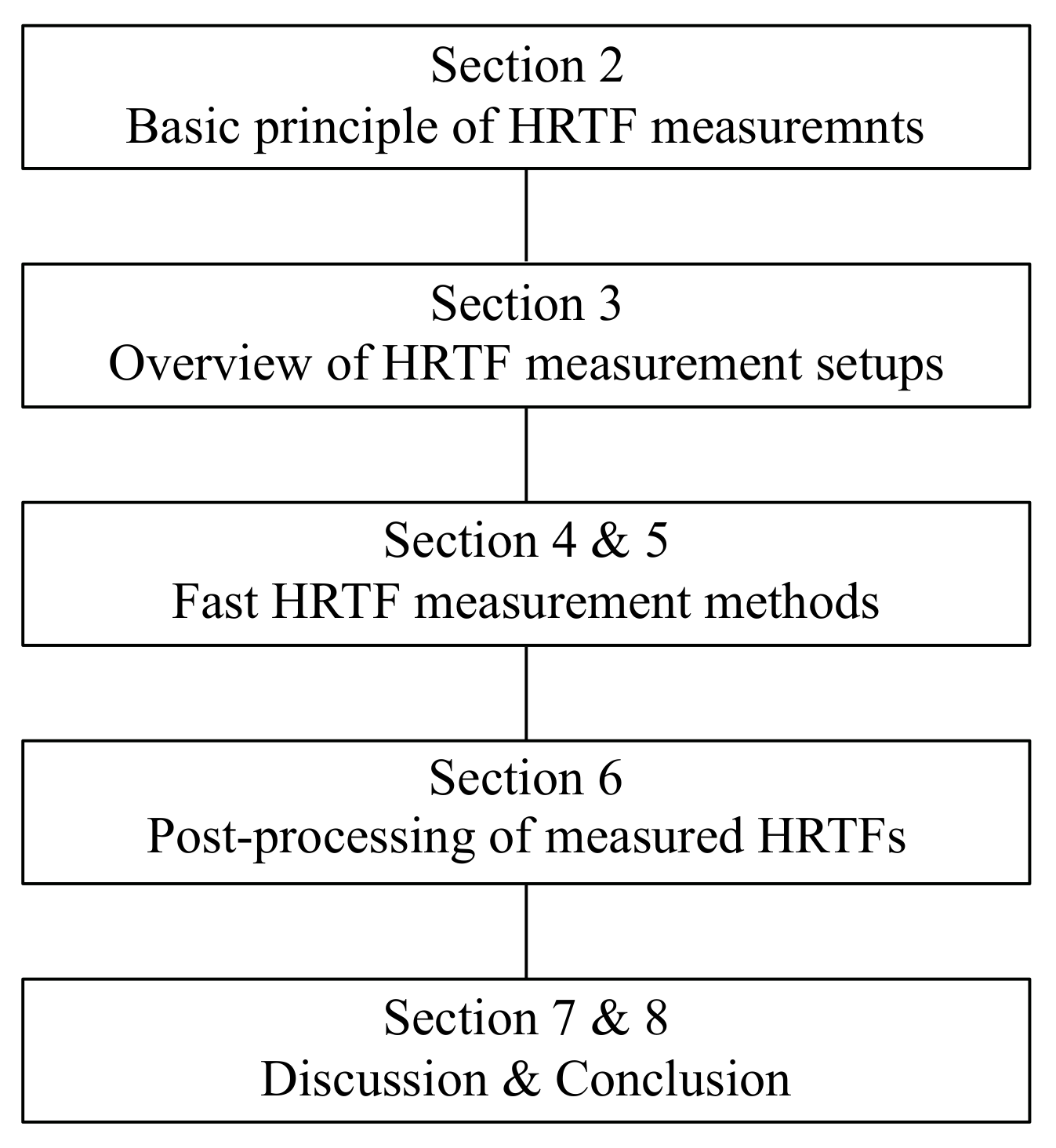
Figure 1. An overall structure of the rest of this review paper.
Applsci 10 05014 g001
Figure 2. Basic principle of signal processing through an LTI system in time and frequency domain (adapted from Figure 7.7 in [6]).
Applsci 10 05014 g002
Figure 3. Block diagram of a basic HRTF measurement setup, including a loudspeaker, a pair of in-ear microphones attached to subject’s ears, a microphone preamplifier, a power amplifier, analog-to-digital/digital-to-analog converters (ADC/DAC) and a computer (adapted from Figure 2.2 in [35]).
Applsci 10 05014 g003
Figure 4. An L-stage linear feedback shift-register for the generation of maximum length sequence (MLS) signals (adapted from Figure 2.1 in [35], published by J. Ross Publishing. All rights Reserved). a i denotes the state of each register, where i { 1 , 2 , 3 , , L } .
Applsci 10 05014 g004
Figure 5. System identification using a pair of Golay codes (adapted from Figure 2 in [55]).
Applsci 10 05014 g005
Figure 6. An example of measured system impulse responses (time-frequency representation) by using linear (upper panel) and exponential (bottom panel) sweeps as excitation signals. The bold and thin curves represent linear and harmonic responses, respectively (adapted from Figure 2 in [73]).
Applsci 10 05014 g006
Figure 7. Block diagram for identifying an unknown discrete system with adaptive filtering approaches in the time domain [56].
Applsci 10 05014 g007
Figure 8. Examples of multi-loudspeaker-based HRTF measurement setups taken from [2,108,116,121,122,123,124,125,126,127,128,129,130,131,132,133,134] (All pictures are taken from available publications, some of them are partly cropped to fit into the overall picture).
Applsci 10 05014 g008
Figure 9. Examples of single-loudspeaker-based HRTF measurement setups taken from [15,78,114,120,136,137,138,139,140,141,142] (All pictures are taken from available publications, some of them are partly cropped to fit into the overall picture).
Applsci 10 05014 g009
Figure 10. Examples of system setups based on the reciprocity theory [57,143,144,145] (all pictures are taken from available publications, some of them are partly cropped to fit into the overall picture).
Applsci 10 05014 g010
Figure 11. Examples of system setups for HRTF measurements in non-anechoic environments [154,155] (The pictures taken from publications are partly modified to highlight measurement setups).
Applsci 10 05014 g011