Article

Enhancing the Ballistic Performances of 3D Warp Interlock Fabric Through Internal Structure as New Material for Seamless Female Soft Body Armor Development

1
Faculty of Science and Technology, University of Lille, Nord de France, 59000 Lille, France
2
École Nationale Supérieure des Arts et Industries Textiles (ENSAIT), GEMTEX lab, 2 Allée Louise et Victor Champier, 59056 Roubaix, France
3
Faculty of Textile, Leather and Industrial Management, ‘Gheorghe Asachi’ Technical University of Iasi, Dimitrie Mangeron Bd., 53, 700050 Iasi, Romania
4
College of Textile and Clothing Engineering, Soochow University, 178 G.J. D. Road, Suzhou 215021, China
*
Authors to whom correspondence should be addressed.
Appl. Sci. 2020, 10(14), 4873; https://doi.org/10.3390/app10144873
Submission received: 3 June 2020 / Revised: 30 June 2020 / Accepted: 13 July 2020 / Published: 16 July 2020
(This article belongs to the Special Issue Advanced Materials for Defense: Designing for Performance)

Abstract

:

Featured Application

Nowadays, 3D warp interlock fabric has become a promising fabric structure to apply in different applications due to its excellent molding ability. However, its performance toward ballistic impact for different threats must be investigated before application. The current research attempts to optimize the ballistic performances of 3D warp interlock fabrics for the development of seamless women’s soft body armor. It was found that the warp yarn compositions inside the fabric structure affected the overall ballistic performances of the 3D warp interlock fabric panel. Samples that comprised nearly appropriate binder and stuffer warp yarn ratio compositions inside the 3D warp interlock fabrics showed better energy absorption and lower BFS values than their counterpart traditional 2D plain fabrics.

Abstract

This paper investigates the effects of warp yarns ratios on the ballistic performances of three-dimensional (3D) warp interlock p-aramid fabrics. Four 3D warp interlock variants with different binding and stuffer warp yarns ratios were designed and developed. Except for warp yarns ratios, similar fabric parameters and manufacturing conditions were considered. Two-dimensional (2D) woven fabric having similar material characteristics and recommended for female seamless soft body armor are also considered for comparisons. Five ballistic panels, one from 2D plain weave fabric and the rest four from the other 3D warp interlock variants were prepared in a non-angled layer alignment and non-stitched but bust-shaped molded form. The ballistic test is carried out according to NIJ (National Institute of Justice) standard-level IIIA. Back Face Signature (BFS) was then modeled and measured to compute both trauma and panels’ energy-absorbing capability. The result showed significant ballistic improvement in the 3D warp interlock variant with optimum warp yarns ratios over traditional 2D plain weave fabrics. 3D warp interlock fabric panel made with 66.6% binding and 33.3% stuffer warp yarn ratio revealed both lower BFS depth and higher energy absorbing capacity (%) than other panels made of 2D plain weave and 3D warp interlock fabric variants.

1. Introduction

Body armor is an equipment used to shield different customers including military and law enforcement agency personnel’s from various threats [1]. Nowadays, both high-speed projectile advancements and higher demands of body armor put pressure on body armor developers, researchers, and manufacturers for a better and progressive improvement of the ballistic protection system not only using appropriate designing techniques but also developing proper materials [2]. Besides, unlike the male, the developments of soft body armor for female working in the various vulnerable areas demands body armor developed with a very highly technical designing skill not only for better ballistic protection but also to accommodate their curvilinear upper torso for better comfort and fitness [3,4,5,6,7]. However, achieving proper female soft body armor not only needs a unique panel design technique but also appropriate material that is moldable, reasonably light in weight, and comfortable without compromising its ballistic performance toward projectile penetration [8]. In general, the ballistic performances of textile-based soft body armor influenced by various internal factors including fiber types, yarn properties, material areal density, target plies numbers, target ply sequence fabric construction, such as woven/nonwoven and 2D/3D fabrics [9,10,11,12,13]. Twaron®, Kevlar®, Dyneema®, and Spectra® are commonly used high-performance fibers to produce body armor systems due to their high resistance-to-impact damage [12,14,15], high strength, high tenacity, good chemical resistance and lightweight characteristics [16,17]. For the last many decades, 2D plain weave and UD fabric structure made from high-strength fibers have been used in personal body armor development due to their excellent mechanical properties and ballistic performances [18,19,20,21,22,23,24]. Such multiple 2D woven fabrics are layered to design ballistic panels with a range of thicknesses and stitched in one or more directions to enhance the ballistic resistance [25,26]. However, despite the ballistic performance, the ballistic fabrics should possess good molding behavior not only to eliminate different defects including shear deformation thickness variations, and wrinkles but also properly accommodating to the women’s frontal body shape while developing body armor. Various researchers have also revealed such 2D plain weave or UD fabrics are not suitable to form the three-dimensional body contours to develop seamless female soft body armor without the involvement of design elements [27,28,29,30]. Nowadays, due to the higher involvement of females in law enforcement, police department, and military services, it is very necessary to engineer and manufacture appropriate materials to accommodate their unique curvilinear body shape without compromising the ballistic performances.
Currently, 3D woven fabrics, particularly 3D warp interlock has become the most promising fabric structure to perform in various technical applications including female soft body armor development due to its excellent molding capability [31,32,33]. In general, molding behavior is one of the most important material behaviors to develop the three-dimensional components of seamless female soft body armor [34]. Several researches have also investigated the molding characteristics of 3D warp interlock fabrics and its capability of shaping deep dome designs without cutting due to its specific characteristics including extraordinary molding properties [35,36,37]. One of our researches has also investigated the molding behaviors and its recoveries of 3D warp interlock fabrics and compared with 2D plain weave fabrics for female seamless soft body armor development [31]. Based on the result, 2D plain weave fabric shows higher punching loads to deform the specific deformational depth, higher drawing-in values and its recovery in all directions as compared to its counterpart 3D warp interlock fabrics preform. Besides, the fabric and yarn density has shown a great impact on its various formability characteristics of 3D warp interlock preforms while deformation. The 3D warp interlock fabrics have also shown good elastic behavior [38], due to their low shear rigidity as compared to other woven fabric structures. However, besides the molding behavior, ballistic protection performances of the material are also a very critical parameter that should be considered while developing female body armor. Various studies have investigated and discussed regarding the ballistic performances of 3D warp interlock fabrics for soft body armor applications. For example, soft body armor made of 3D orthogonal woven, 3D angle interlock woven and 3D fully/partly interlaced woven as well as multi-axis 3D woven or knitted preforms have been investigated against ballistic performances [39,40]. Besides, ballistic panels made of 3D woven fabrics revealed better molding ability and equivalent ballistic performance as compared to panels made from 2D plain weave fabric structures [41,42]. This makes the fabric a promising material to develop the frontal women’s soft body armor panel by properly accommodating the upper torso shape and the bust [3,29]. Such behavior then gives both the comfort and enhanced ballistic performance by removing the stitching and other weakening material surface during traditional manufacturing. Even though the 3D warp angle-interlock fabrics possessed an excellent forming property, some researchers have also claimed that 3D warp interlock fabrics have shown less ballistic performance as compared to the traditional 2D plain weave fabrics. Our recent research studies have compared the energy absorbing capability and its BFS values of ballistic panels made of 2D plain and 3D warp interlock fabrics based on NIJ-standard Level IIIA. Based on the result, the energy absorption capabilities of 3D warp interlock and 2D fabric panels with a higher number of layers did not reveal a significant difference. However, the 2D fabric panel absorbed more energy than 3D warp interlock fabrics for a reduced and similar number of layers due to its rigid and stiffness property [37,43]. Therefore, very well understanding and improving the ballistic impact performances of the 3D warp interlock fabric before applying to female soft body armor development is very important.
The current research investigates the ballistic performances of 3D warp interlock fabrics considering the involvements of different warp yarns (binding and stuffer) interchange ratios inside the structures. This greatly helps to determine an appropriate warp yarn orientation and interchange ratio inside the fabrics to enhance the ballistic performances of the 3D warp interlock fabrics. Besides, the investigation also compares the 3D warp interlock fabrics ballistic performance with the comparable 2D plain weave fabrics made with similar material and parameters. For this, different 3D warp interlock fabrics based on different binding: stuffer warp yarn interchange ratios inside the structure were designed, engineered and manufactured. The ballistic performance test was carried out according to the US NIJ—National Institute of Justice (NIJ Standard-0101.06) in the confined division of Centre de Recherche et expertises de La Logistique (CREL) ballistic facility, Paris, France. The backface signature for each panel target shots was scanned using a precise portable scanner, modeled, and measured by the help of modeling software (Rapidform® and 3D design concept®). Moreover, two separate high-speed cameras were installed for stereoscope recording to capture and observe closely the overall ballistic phenomena. In general, the study will give a great insight into not only the effects of binding and stuffer warp yarns inside the 3D warp interlock structure but also the woven construction types (2D and 3D) on the ballistic performances as ballistic material in the developments of seamless women ballistic vest.

2. Materials and Methods

2.1. Materials

2.1.1. 3D warp Interlock Fabrics Design and Manufacturing Process

3D Warp Interlock Fabrics Design

In general, the commercially available fabric weave-design software such as TexGen® and WiseTex® are widely used to design 2D plain woven and complex 3D woven fabric architecture. In the current study, TexGen® software was used to geometrically model all the intended 3D warp interlock fabric architectures. Different binding and stuffer warp yarn interchange ratios, namely 100% binding and 0% stuffer (3D-8B:0S), 66.7% binding and 33.5% stuffer (3D-8B:4S)), 50% binding and 50% stuffer (3D-8B:8S), and 33.3% binding and 66.7% stuffer (3D-4B/8S) inside the 3D warp interlock fabric structure were considered. Applying different warp yarn interchange ratio inside the fabric structure could affect not only its fabric weave repeat unit but also the overall fabric structures. The weave repeat unit is the smallest constituents of the fabric structure which is combined in an extended repeat pattern form to form the overall fabric structures. The 3D warp interlock fabric structures design was then conceived by the PointCarre® software to prepare its peg plans before the fabric productions. In the peg planning process, all the fabric structures were drafted with the same weave drafting plan and similar weaving loom adjustment for easy production and time-saving purposes. Such arrangements provide the production of all 3D warp interlock fabric variants by only changing only the weave designs.

3D Warp Interlock Fabrics Production

An adapted ARM semiautomatic dobby loom was used to manufacture all the 3D warp interlock fabric architectures as shown in Figure 1. The weaving loom was equipped with a 24 warp beam to produce the intended 3D warp interlock fabric structures. In preparation, each beam was loaded on a customized warp beam creel which is designed to accommodate the specified number of the warp beams (Figure 1a). The individual warp yarn ends from each beam were then carefully and separately inserted through the hole of horizontal warp yarn tension guiding systems as shown in Figure 1b. This will help to adjust and control the yarn tension during the weaving process.
For better shed opening process, yarn ends from each warp beam were controlled with the specific heald shaft. This greatly helps to properly control the shed opening not only for better design accommodation but also to reduce yarn degradation during the weaving process as shown in Figure 1c. A 50 cm long reed made of metals having a reed dents of 12 dents/cm were used to accommodate the 100 warp ends which comes from the same beam. This would also help to accommodate one beam warp ends in one shaft. In the weaving process, the required design was selected automatically from control panel heads which can store and read the peg plan design, but the shed opening, pick-up, and beating were carried out manually. The high-performance para-aramid yarn with 930dtex (called Twaron®) was purchased from Teijin Aramid, a subsidiary of the Teijin Group. All the yarns were twisted at room temperature using Twistec machine with 25 twists per meter (TPM) throughout the fiber for intended fabrics production. Such yarn is used to produce the common and recommended 2D plain weave by the Teijin Company to develop female ballistic. This is due to its good ballistic performance and high level of foldability. While manufacturing all the 3D warp interlock fabric variants, balanced fabrics with the same warp and weft yarn densities, fiber linear density (930dtex), and same weft layers (5 layers) were used. Figure 2 shows the different manufactured 3D warp interlock orthogonal layer-to-layer fabric variants at the top and side view (weft layer).
Moreover, 2D plain weave fabrics (CT-709) made of similar material (fiber and yarn) characteristics and fabric areal density with the developed 3D warp interlock fabric variants were also used for ballistic performance comparisons. The theoretical and actual fabric areal densities of all the considered fabric were found almost similar. Different parameters and specifications of the utilized high-performance para-aramid fiber and the 3D warp interlock fabric variants are indicated in Table 1.

2.2. Ballistic Panel Preparation, Ballistic-testing Procedure and Backface Signature Values

This section will discuss on the preparations of targets from the different variants of 3D warp interlock and 2D plain weave fabrics, the ballistic-testing standards and protocols and measurements of the backface signature created at the back of the clay for further performance analysis. Before discussing each section in details, the schematic views how the sample prepared, the testing protocol and BFS measurements systems are presented in Figure 3.

Ballistic Target Panels Preparations

In the current ballistic investigations, a total of five target panels in which four panels made from the developed 3D warp interlock orthogonal layer-to-layer fabric variants were arranged in a non-angled alignment and non-stitched system. The rest one target panel was prepared from the 2D plain weave para-aramid fabrics (Twaron-CT-709). Generally, all the target panels made from 3D warp interlock were arranged with 8 panels (40 weft layers) each and the other target panels from 2D plain weave fabric comprise 35 layers. However, the final panel target made from both fabric types (2D plain and 3D warp interlock fabrics) was planned to possess similar panel fabrics areal densities. The prepared target panel descriptions are presented in Table 2.
Later, as described in the above, all the fabric layers of the target panels were arranged in the aligned fabrics panel’s orientations and one over the other. Moreover, neither lamination nor any other form of binding methods were applied to bind the different panel layers together while target preparations.
However, the final target was firmly taped together at the edge using scotch tapes to avoid both the fiber unraveling and layers slippage from original positions during ballistic testing. A very dense and random dot speckle pattern on the specified regions of the shooting points (10 cm × 10 cm) was systematically drawn to better recording of the ballistic event using a super-high-speed camera. Such a dot pattern was drawn on the strike faces of the target panel as shown in Figure 4. Later, all the panels were supposed to be molded at the two pre-defined points to mimic the frontal contour of the specific women’s body before ballistic test. The bust shaped punch and an adapted forming bench (Figure 4d) were used to mold each panel for the desired shapes

2.3. Ballistic-testing Procedure and Methods

Ballistic Impact Testing

In general, there are various methods of testing and evaluating the ballistic performance of the material. In our research, the non-penetration ballistic testing approach was applied to evaluate the back face indentations at the backing clay and panel’s energy absorption capabilities of the target panel. The ballistic testing was carried out based on NIJ Standard-0101.06 Level IIIA [44]. Such testing standard mainly helps to establish the minimum and maximum ballistic performance requirements of personal soft body armor systems. Based on the NIJ standard Level IIIA, six gunshots were performed per each panel at different and very specific shot points. Among the 6 different shots per panel, 3 bullets were performed on and around the bust-shaped molded panel area, whereas the rest 3 bullets were tested on the selected non-molded panel surfaces were performed. Figure 5 shows the ballistic testing equipment and its set up for testing.
Besides, shot 1 and 4 were performed around the edges of the molded area, and shot 5 was tested on the center of the molded surface for further exploitation of the result and better analysis. Besides, shot 6 and 2 were carried out on the upper center and lower right corner non-molded panel areas. Furthermore, shot 3 was conceded on between and center of the two bust-shapes molded area as shown in Figure 4. Such proper and even distributions of the different shots throughout the different parts of the panels were allocated based on NIJ standard testing conditions for Unisex body armor. Such arrangements of shots ultimately supports to assess the performances of the various panel parts while ballistic testing. Each prepared target panel along with the backing materials was then carefully and firmly attached to the box holding frames before every shot. The backing box holding frames were positioned at a distance of 10 m from the nose of a 280 mm longer gun barrel as shown in Figure 5.
Two types of projectile velocity by the Doppler radar system and chronograph were obtained after the test. A WEIBEL model SL-52OP with 10,525 GHz Doppler radar system was installed at 5m from the firing gun nozzle position to measure the initial impact velocity. Model 414 Sabre ballistic laser barriers were also placed at a distance of 5 m from the panel target to detect the missed velocity from the radar. Whereas, the chronograph was placed at the 9 m position from the gun nozzle to measure the impact velocity near the target panel system. Moreover, two Phantom V1212 high-speed cameras with 56,000 fps, 384 x 400 pixels, and 280 mm focal length are used by placing one on the right and the other on left axis of shooting at the front. Moreover, the two cameras are also placed at an angle of 45° with shooting axis with a distance of 3.65 m from the target in order to properly capture the ballistic phenomenon during the test. The molded target panels were then properly mounted on the four sides of plastilina box using narrow fabrics with Velcro tape at uniform clamping pressure. Higher or lower clamping pressure during clamping the target causes inconsistent impact results. Finally, the ballistic shots on the molded and non-molded target panel areas according to the plan carried out. The ballistic tests were conducted at the Centre de Recherche´ et d’Expertise De La Logistique (CREL) of France. The different testing parameters and conditions during the test are described in Table 3.

2.4. Measurements of Backface Signature Depth, Diameter and Volumes

2.4.1. Scanning of Backface Signature at the Back of Plastilina

The backface signature measurement is one of the parameters which could help to assess the energy absorbed and other ballistic performances of the ballistic materials. It is normally produced on the back of the ballistic material during the ballistic impact. Therefore, the backface signature should be measured with great care and accuracy. Unlike the traditional BFS measurement systems (using caliper or rulers), the current research has introduced a new system for precise and quick measurements of the different BFS values. Such measuring system involves scanning of the shot backing material through hand scanning. Later, the scanned images has been cured using rapid form software and then modeling and measured its values (depth and volume) using 3D modeling software. Before scanning, the panel target along with the backing material box (Figure 6) was detached from the fixed ballistic box holder. Then, the panel target will be carefully removed from the backing material. This would help not only to keep the tested target but also not to distort the BFS measurements created on the backing material surfaces. According to NIJ Standard, the backface signature depth should not be greater than 44 mm; otherwise, it will bring a fatal injury in the vital organ of the wearer. During the impact, the projectile might perforate the panel and pass throughout the thickness or stuck inside the fabrics. In the non-perforation case, the projectile will be stopped inside the panel or rebound back by creating some back face indentation on the backing material. Thus, such back face indentations on the backing clay should be measured after each panel shooting for analyzing the ballistic performances of the panel target. Various reflecting dot marks were placed on the deformed backing material surface for easy detection and modeling of the backface indentation before scanning. Later, the back face indentation on the backing clay was scanned at a time after shooting all the 6 projectiles on the panel target using a handy scanner as shown in Figure 6. Such scanning methods not only give a better scanning process and precise measurement but also it is a time-saving process.
Using such a handheld scanning device greatly used to better handle the measurement process and scan the molded surface with very clear and precise 3D model representations. Besides, as shown from Figure 7, only the face of the target panel with no perforation during ballistic tests at different shots was displayed. The handy scanner displays a very good resolution with accurate high- and low-resolution scan modes. The resolution measurement is 0.050 mm with an accuracy of 0.040 mm. The volumetric accuracy and laser cross-area are 0.020 mm, 0.100 mm/m and 210 mm × 210 mm, respectively. It was employed to capture the whole backing material surface without any physical contact for further computing of the backface signature values.

2.4.2. Modeling and Measurements of Backface Signature Values

The BFS measurements were measured and computed using various methods and principles after scanning of each impacted backing material surfaces of that particular target panel on the corresponding ballistic shot. Such precisely measuring and analyzing of the back face signatures after each test could greatly help to determine not only whether the intended armor panels will provide adequate protection against the specific projectile but also to compute the amount of energy absorbed by each target panel. In the non-perforation methods, the depth, diameter, and volume of BFS are considered for further analysis only if the shooting bullet did not pass through the panel target.
In general, the BFS values for each target panel normally indicate how much the bullet kinetic energy with the specified velocity was either absorbed by the panel target or transmitted to the backing materials. For example, computing the BFS volume of each panel target shot from scanned and modeled geometry helps to determine the amount of energy absorbed and energy transmitted beyond the target panel. Finally, the scanned backing surface with BFS values was first cured by Rapid Form software and later transferred to 3D modeling software (3D design concept) to precisely model and measure each target test of the backface signature as shown in Figure 8.

3. Results and Discussions

3.1. Ballistic Performances of the 3D Warp Interlock Fabrics

In general, the ballistic impact mechanism is a very complex dynamic process which mainly depends on the internal (thickness, strength, ductility, toughness and density of material) and external factors (projectile parameters, target conditions and testing parameters). During the ballistic impacts of fibrous textile materials, different phenomenon such as complete perforation of target with certain residual velocity, complete perforation of target with zero residual velocity or partial perforations of the target could happen depending on the material. Besides, the incident kinetic energy of the projectile would be absorbed by the panel through various kinds of damage and energy absorbing mechanisms. In our investigations, as discuss previously, a non-perforation testing method which uses a backing material at the back of panels was used during the test. Thus, according to NIJ standard, the blunt trauma effect and the energy absorption capability of the panels which undergo in a non-perforation test will be computed based on the BFS values on the back of the panel (backing surface) after the test. Figure 9 shows the schematic views of overall ballistic performance analysis of the panel after non-perforation tests.

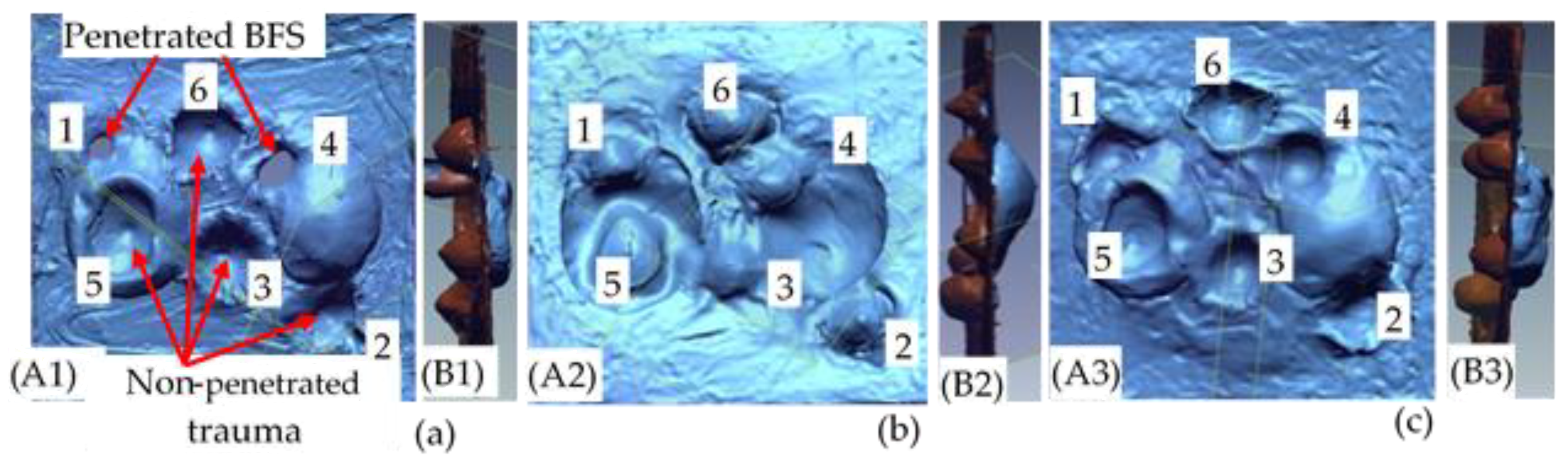
3.1.1. Analysis of Backface Signature Depth and Diameter Values.

The BFS maximum depth and the average diameter values of the tested panels are indicated in Figure 10 and Figure 11 respectively. Based on the result, generally, the different warp yarn orientation and its ratios inside the structures show a great influence and improvement on the panel’s BFS depth and diameters. Involving higher proportions of either binding or stuffer warp yarns inside the 3D warp interlock fabrics brought lower ballistic performance. For example, a sample with a higher stuffer warp yarns proportional ratio (sample 3D-40- 4B:8S) faces a complete penetration in all shot points compared to other 3D warp interlock fabrics. Moreover, another target panel made of 3D warp interlock fabric with 100% binding warp yarns (sample 3D-40-8B:0S) were penetrated at the two-shot points, namely shot points 1 and 4. On the contrary, 3D warp interlock fabric samples made with equal or a bit higher interchange ratio of the binding and stuffer warp yarn inside the 3D fabric shows lower back face signature depth values. For instance, as shown in Figure 10, samples 3D-40-8B:4S and 3D-40-8B:8S shows no perforation with less back face indentation depth values of the maximum allowed standard values (44 mm).
However, except in target shot point 5, sample 3D-40-8B:4S shows lower backface indentation depth as compared to its counterpart panel made with the same number of 3D warp interlock fabric layers but different warp yarn interchange ratio, sample 3D-40-8B:8S. Numerically, 3D-40-8B:4S shows the minimum and maximum backface indentation value of 20.5 mm and 32 mm in shots 4 and 6 respectively. Sample 3D-40-8B:8S also shows the minimum and maximum backface indentation values of 23 mm and 36 mm in shots 4 and 2 respectively. Sample 3D-40-8B:0S faced penetration at two-shot locations (shot 1 and shot 4) which are located on edges of the right and left deformed bust shapes.
Whereas, sample 3D-40-4B:8S were fully penetrated in all the shot points. Besides, the type of fabric constructions (2D and 3D woven) used in the panels was also observed as one of the factors that affect the backface indentation measurements. Samples made of 2D plain weave fabrics having with similar areal density of 3D warp interlock fabrics was penetrated at one shot point (shot 6). Similarly, except for shooting locations 3 and 5, sample 3D-40-8B:4S also shows lower trauma depth values as compared to sample 2D-35. The BFS depth values for the 3D warp interlock fabric structure made with various warp yarns interchange ratios were also revealed higher and nearly similar values among molded shot points (shot 5) compared to the majority of other non-molded shot location (Figure 11). For example, except 3D-40-4/8 where all are penetrated, the maximum BFS depth for the 3D-40-8B:0S, 3D-40-8B:4S, 3D-40-8B:8S and 2D-35 were recorded 32, 31, 30.5 and 30 mm respectively at the molded panel area of shot point 5. Unlike other non-molded shot point areas, such back-face signature depth increments in the molded area are due to occurrences of fabric density (thickness) reduction and yarn filament damages during the forming process through stretching of the fabric. Moreover, the influence of warp yarns interchange ratio in 3D warp interlock fabric on average BFS diameter values are also investigated as shown in Figure 11. According to these investigations, sample 3D-40-8B:4S shows a lower BFS diameter compared to all other samples made with 3D warp interlock weave fabric architectures.
On the contrary, sample 3D-40-8B:0S revealed the highest BFS diameter compared to its entire counterpart 3D warp interlock fabric sample, except sample 3D-40-4B:8S where all of its target position were penetrated. Except for its penetration at shot point 6, sample made with 2D plain weave fabric (2D-35) records lower BFS diameter at shot 2 and 5, but higher at shot points 1 and 4 as compared to samples made of 3D warp interlock structures. Sample 2D-35 revealed lower BFS values compared to 3D-40-8B:0S and 3D-40-4B:8S for shot point except shot 6. In contrary, Sample 2D-35 revealed higher values than sample 3D-40-8B:4S followed by 3D-40-8B:8S in the majority of the target shot. Moreover, among all the 2D and 3D warp interlock fabric samples, 3D-40-8B:4S revealed much lower BFS diameter in the majority of the target shot. The conditions of the sample (molded and non-molded target situations) could also reduce the ballistic performances and increased the BFS depth of the final panels at the specified target points.

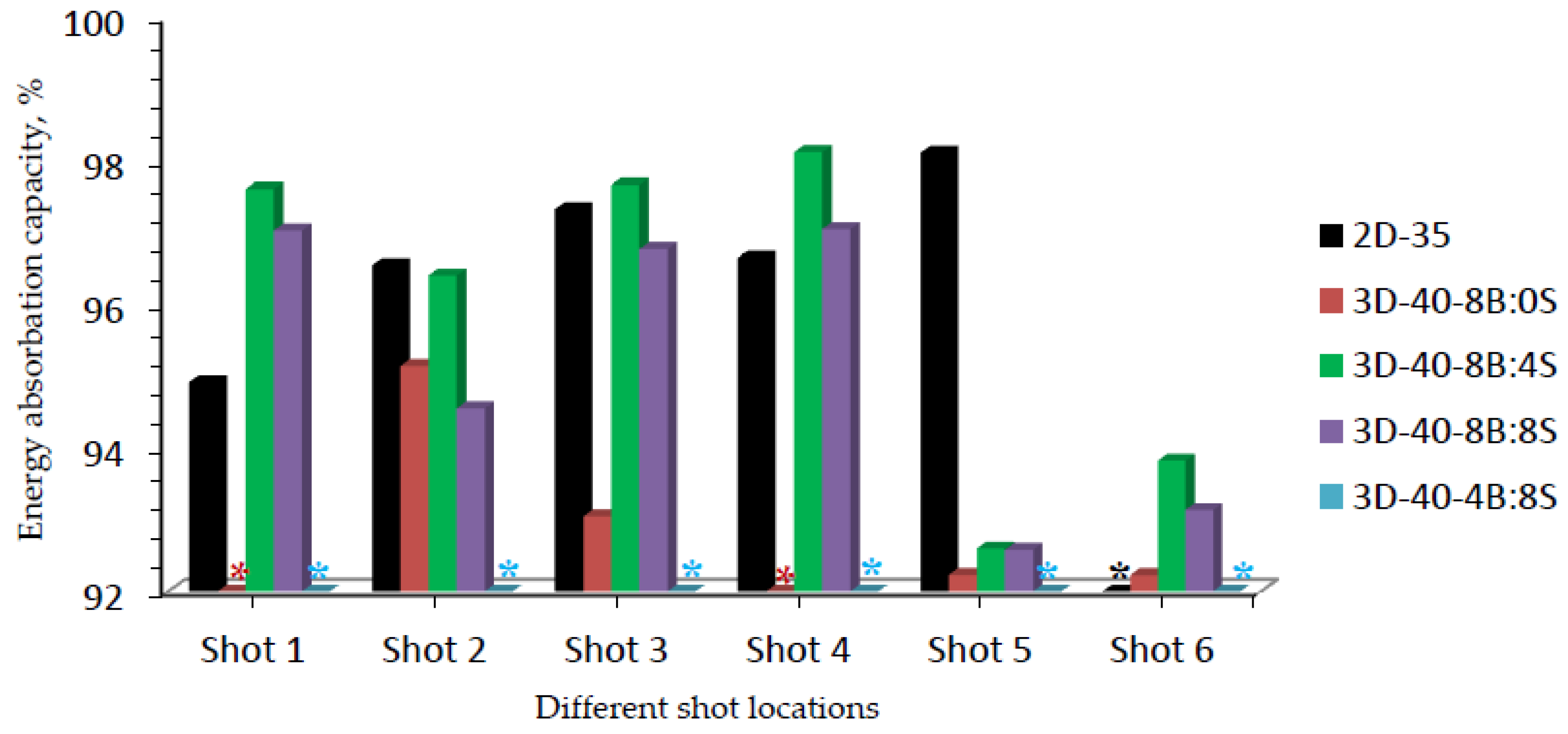
3.1.2. Energy Absorption Capabilities of 3D Warp Interlock Fabrics

Enhancing a fiber-based textile made soft body armor panel performance requires a full understanding of its different ballistic impact mechanisms during the ballistic impact process. Understanding exactly the energy absorbing mechanisms of the material is one of the methods to know the ballistic impact phenomenon of the panel target. Normally, the impact energy of ballistic fabric panels with high-speed projectile will be converted into various forms mainly to kinetic energy. Such converted kinetic energy will be then either absorbed by the fabric panels or transmitted to the back of the material which could create some trauma indentations. Enhancing the energy absorbing capability of the fabric could ultimately reduce the trauma and injury created at the back of the panels. Considering material type, fabric structure, fabric finishing, fabrics areal density, panel arrangement areal density, etc. are some of the major parameters that could influence and enhance the energy-absorbing capabilities of the final fabric panels. Besides, shock wave propagations on the panel surface could be also generated by the impact energy. Such dynamic impact mechanisms bring the probability of destructing different fabric elements including filaments, fibers, and yarns.
So far, various techniques have been involved to derive the constitutive relations and model the overall fabric ballistic mechanisms against impacts to better understand, improvement, and use in different applications. Generally, two types of yarn are involved in the fabric during projectile impacts. The first are primary yarns which is in direct contact with the projectile, whereas, secondary yarns are those yarns that are not in direct contact with projectile [8].
For fully penetration testing conditions, the energy absorbed capacity by the fiber-based woven fabrics will be calculated as follows:
E m   = 1 2   m   ( v i 2   v e 2 ) ,   if   v i >   v p
E m   = 1 2   m   v i 2   ,   if   v i <   v p
where,
  • m is the projectile mass (kg);
  • vi is the impact velocity of the projectile (m/s);
  • ve is the exit velocity of the projectile (m/s);
  • vp is the penetration velocity of the projectile (m/s);
  • Em is the projectile energy loss (joule).
Such an equation is normally used to determine the ballistic limits of soft body armor panels. However, in the current research study, the non-penetration ballistic testing condition has been carried out to investigate the overall ballistic performances of the 3D warp interlock fabric structures. Besides, unlike the penetrated testing approach, the non-penetrated testing conditions could use different BFS measurements to compute the panel’s energy-absorbing capabilities. For instance, according to the NIJ standard, the BFS volumes of each shot on the backing material could help to compute the ballistic targets absorbed and transmitted energy values at the corresponding shot points. In general, the higher back face signature volume at the back of the ballistic panel target, the higher amount of energy could be transmitted to the back of the ballistic panels and vice-versa.
Based on the investigation, Figure 12a, b shows the energy absorbed and transmitted values respectively for various 3D warp interlock panels and 2D plain weave p-aramid fabrics.

3.1.3. Normalizations of Energy Absorption Capabilities of 3D Warp Interlock Fabrics

The initial impact energy for all samples at their corresponding impact shot point might vary due to the different projectile impact velocity. Thus, the calculated energy absorbed values by the panel and transmitted energy to the backing panels might not be a good performance measurement for each panel targets. Considering this, normalizing the energy absorbing capacity of each sample with their corresponding shot points based on the initial total impact energy would be an appropriate approach for better comparison. A significant difference in energy-absorbing capability (%) was also observed among 3D warp interlock fabrics and 2D plain fabric panels at different shot points. Figure 13 shows the energy-absorbing capacity (%) of each sample made of the different binding: stuffer interchange ratio of 3D warp interlock fabrics and 2D plain weave fabric at different shot points.
Different energy absorption percentage values were also observed at different shot points within the same ballistic panel targets. Sample 3D-40-8B:4S shows a higher percentage of energy-absorbing capability in majority target shot points of both molded and non-molded target areas as compared to other samples made with 3D warp interlock fabrics.
In the normalized graph, 3D-40-8B:4S also revealed better absorbing capacity at target shot points 1, 3, 4, and 6 as compared to samples made with 2D plain weave (2D-35). This due to the involvements of the two yarn systems in the larger areas for better dissipations of the energy. Besides, the involvements of binding warp yarn helps to absorb more energy due to its waviness properties. Thus, the maximum and minimum absorbed energy capabilities (%) of 3D-40-8B:4S was recorded as 98.1% and 92.6% in target shot point 4 and 5 respectively. Even though 3D warp interlock fabric shows good molding ability [31,45], the energy capability of the 3D-40-8B:4S was reduced in the molded area (shot 5). This is due to its low molding recovery behaviors which in turn minimize the fabric thickness along tensioning of fibers on the specific molded area. Such a mechanism could reveal the reduction of the energy-absorbing capability and hinders the ballistic performances of that particular region. Moreover, sample 3D-40-8B:8S revealed 97%, 94.5%, 94.5%, 96.7%, 97%, 92.6% and 93.1% energy-absorbing percentage for shots 1, 2, 3, 4, 5, and 6 respectively. Unlike shots 1 and 4 where full penetrations occurred, sample 3D-40-8/8 also recorded 95%, 93%, 92.2%, and 92% for shot points 2, 3, 5, and 6 respectively. This generally shows that a 3D warp interlock fabric should involve an optimized and balanced warp yarn ratios inside its structure for better ballistic performances and lower BFS effects. Considering 2D plain weave fabrics, sample 2D-35, except penetration at shot 6, it exhibited a 94.89%, 96.52%, 97.3%, 96.62%, 98.09% energy absorption capability for shot 1, 2, 3, 4 and 5 respectively. Unlike our previous studies [37], samples made of 2D plain weave fabric shows higher energy absorbing capabilities on the molded area of the panel (shot 5) than samples made with 3D warp interlock fabrics. This might be due to quick molding recovering of the panels at molded bust areas before ballistic testing. Based on these results, it is indicated that, like other parameters such as fiber type, fabric architecture, panel system, etc., the energy absorbing capacity of panels made of 3D warp interlock fabrics was greatly affected by the warp yarns interchange ratio inside the architecture as well.

4. Conclusions

The purpose of this research was to enhance the ballistic performances of the 3D warp interlock fabric considering appropriate internal warp yarn structural compositions for seamless female soft body armor development. Four different 3D warps interlock architecture which comprises 8:0, 8:6, 8:8, and 4:8 of binding: stuffer warp yarn ratio inside the structure was designed and manufactured. 2D plain weave fabrics (CT-709) made of the same types of material and yarn densities are also considered for comparison. One target panel from 2D plain weave fabric and another four target panels from each 3D warp interlock fabrics were molded with a bust-shaped punch to mimic the frontal seamless female upper torso shape before testing. The ballistic test based on NIJ Level-IIIA standard shows that samples with no stuffer warp yarn (3D-40-8B:0S) and maximum stuffer warp yarn ratios (3D-40-4B:8S) shows perforation at two-shot points and six (all) shots points respectively. On the contrary, samples with balanced binding and stuffer warp yarn ratios (3D-40-8B:8S and 3D-40-8B:4S) performs very well against perforation in all shot points. Besides, samples made of two-dimensional fabrics (2D-35) were penetrated in shot point 6. Besides, sample 3D-40-8B:4S revealed better BFS depth and diameter measurement (lower BFS values) as compared to sample 2D-35 and other 3D warp interlock variants. On the contrary, sample 3D-40-8B:0S recorded the highest BFS diameter as compared to all 3D warp interlock fabric samples, except 3D-40-4B:8S where its entire target points were penetrated. A significant difference in energy-absorbing capability (%) was also observed among 3D warp interlock fabrics and 2D plain fabric panels at different shot points. The energy-absorbing percentage value was found higher for sample 3D-40-8B:4S than 3D-40-8B:8S and 2D-35 panels for majority shot points. This generally shows that a 3D warp interlock fabric should involve an optimized and balanced warp yarn ratios inside its structure for better ballistic performances and lower BFS effects.

5. Patents

The data involved in this research work are under submission process for a patent as ‘new 3D woven structure for seamless soft body armor development’.

Author Contributions

Conceptualization, M.A.A. and F.B.; methodology, M.A.A., F.B. and I.C.; software, M.A.A., F.B., P.B. and I.C.; validation, M.A.A., F.B., P.B., C.L. and I.C.; formal analysis, M.A.A.; investigation, M.A.A.; resources, F.B., P.B., C.L. and I.C.; data curation, M.A.A., F.B., P.B. and I.C.; writing—original draft preparation, M.A.A.; writing—review and editing, M.A.A., F.B., P.B., C.L. and I.C.; visualization, M.A.A., F.B., P.B., C.L. and I.C.; supervision, F.B., P.B., C.L. and I.C.; project administration, P.B. and C.L.; funding acquisition, P.B., F.B. and C.L. All authors have read and agreed to the published version of the manuscript.

Funding

This research was funded by the European Erasmus Mundus Program, as part of the Sustainable Management and Design for Textiles (SMDTex) Project; grant number SMDTex-2016–6.

Acknowledgments

The authors would like to thank all the crewmembers of the “Centre de Recherche et d’Expertise de La Logistique (CREL)” in Paris involved in the ballistic impact tests, with special thanks to M Audigier and M Mauzac. Authors would like to thank M Bergerard from Avi Speed Company, Menestreau-en-villette, France to provide useful tips while recording high-speed camera movies of ballistic impact tests. Authors would like also to thank M François Dassonville for his help during the ballistic tests and scanning of blunt trauma deformation in the backing material as well as M Lucas Putigny for his help during the weaving session.

Conflicts of Interest

The authors declare no conflict of interest.

References

  1. El Messiry, M.; El-tarfawy, S. Performance of Weave Structure Multi-Layer Bulletproof Flexible Armor. In Proceedings of the 3rd Conference of the National Campaign for Textile Industries, NRC Cairo, “Recent Manufacturing Technologies and Human and Administrative Development”, Cairo, Egypt, 9–10 March 2015; pp. 218–225. [Google Scholar]
  2. Othman, A.R.; Hassan, M.H. Effect of different construction designs of aramid fabric on the ballistic performances. Mater. Des. 2013, 44, 407–417. [Google Scholar] [CrossRef]
  3. Abtew, M.A.; Bruniaux, P.; Boussu, F.; Loghin, C.; Cristian, I.; Chen, Y.; Wang, L. Female seamless soft body armor pattern design system with innovative reverse engineering approaches. Int. J. Adv. Manuf. Technol. 2018, 98, 2271–2285. [Google Scholar] [CrossRef]
  4. Abtew, M.A.; Bruniaux, P.; Boussu, F.; Loghin, C.; Cristian, I.; Chen, Y.; Wang, L. A systematic pattern generation system for manufacturing customized seamless multi-layer female soft body armour through dome-formation (moulding) techniques using 3D warp interlock fabrics. J. Manuf. Syst. 2018, 49, 61–74. [Google Scholar] [CrossRef]
  5. Chen, X.; Yang, D. Use of Three-dimensional Angle-interlock Woven Fabric for Seamless Female Body Armor: Part II: Mathematical Modeling. Text. Res. J. 2010, 80, 1589–1601. [Google Scholar] [CrossRef]
  6. Mahbub, R.; Wang, L.; Arnold, L. Design of knitted three-dimensional seamless female body armour vests. Int. J. Fash. Des. Technol. Educ. 2014, 7, 198–207. [Google Scholar] [CrossRef]
  7. Abtew, M.A.; Bruniaux, P.; Boussu, F.; Loghin, C.; Cristian, I.; Chen, Y. Development of comfortable and well-fitted bra pattern for customized female soft body armor through 3D design process of adaptive bust on virtual mannequin. Comput. Ind. 2018, 100, 7–20. [Google Scholar] [CrossRef]
  8. Cunniff, P.M. An Analysis of the System Effects in Woven Fabrics Under Ballistic Impact. Text. Res. J. 1992, 62, 495–509. [Google Scholar] [CrossRef]
  9. Karahan, M.; Jabbar, A.; Karahan, N. Ballistic impact behavior of the aramid and ultra-high molecular weight polyethylene composites. J. Reinf. Plast. Compos. 2015, 34, 37–48. [Google Scholar] [CrossRef]
  10. Bhatnagar, A.; Arvidson, B.; Pataki, W. Lightweight Ballistic Composites, Military and Law-Enforcement Applications; Woodhead Publishing: Cambridge, UK, 2006; pp. 213–214. [Google Scholar]
  11. Cork, C.R.; Foster, P.W. The ballistic performance of narrow fabrics. Int. J. Impact Eng. 2007, 34, 495–508. [Google Scholar] [CrossRef]
  12. Yavaşa, M.O.; Avcıa, A.; Şimşirb, M.; Akdemir, A. Ballistic performance of Kevlar49/UHMW-PEHB26 Hybrid Layered- Composite. Int. J. Eng. Res. Dev. 2015, 7, 1–20. [Google Scholar] [CrossRef]
  13. Wang, Y.; Chen, X.; Young, R.; Kinloch, I.; Garry, W. An Experimental study of ply orientation on ballistic impact resistance of multi-ply fabric panels. Compos. B Eng. 2015, 68, 259–265. [Google Scholar] [CrossRef]
  14. Zee, R.H.; Hsieh, C.Y. Energy absorption processes in fibrous composites. Mater. Sci. Eng. A 1998, 246, 161–168. [Google Scholar] [CrossRef]
  15. Zhang, Y.D.; Wang, Y.L.; Huang, Y.; Wan, Y.Z. Preparation and Properties of Three-dimensional Braided UHMWPE Fiber Reinforced PMMA Composites. J. Reinf. Plast. Compos. 2006, 25, 1601–1609. [Google Scholar] [CrossRef]
  16. Tan, V.B.C.; Tay, T.E.; Teo, W.K. Strengthening fabric armour with silica colloidal suspensions. Int. J. Solids Struct. 2005, 42, 1561–1576. [Google Scholar] [CrossRef]
  17. Dong, Z.; Sun, C.T. Testing and modeling of yarn pull-out in plain woven Kevlar fabrics. Compos. A Appl. Sci. Manuf. 2009, 40, 1863–1869. [Google Scholar] [CrossRef]
  18. Das, S.; Jagan, S.; Shaw, A.; Pal, A. Determination of inter-yarn friction and its effect on ballistic response of para-aramid woven fabric under low velocity impact. Compos. Struct. 2015, 120, 129–140. [Google Scholar] [CrossRef]
  19. Yang, C.C.; Ngo, T.; Tran, P. Influences of weaving architectures on the impact resistance of multi-layer fabrics. Mater. Des. 2015, 85, 282–295. [Google Scholar] [CrossRef]
  20. Karahan, M. Comparison of Ballistic Performance and Energy Absorption Capabilities of Woven and Unidirectional Aramid Fabrics. Text. Res. J. 2008, 78, 718–730. [Google Scholar] [CrossRef]
  21. Zhang, D.; Sun, Y.; Chen, L.; Zhang, S.; Pan, N. Influence of fabric structure and thickness on the ballistic impact behavior of Ultrahigh molecular weight polyethylene composite laminate. Mater. Des. 2014, 54, 315–322. [Google Scholar] [CrossRef]
  22. Bandaru, A.K.; Vetiyatil, L.; Ahmad, S. The effect of hybridization on the ballistic impact behavior of hybrid composite armors. Compos. B Eng. 2015, 76, 300–319. [Google Scholar] [CrossRef]
  23. Nguyen, L.H.; Ryan, S.; Cimpoeru, S.J.; Mouritz, A.P.; Orifici, A.C. The effect of target thickness on the ballistic performance of ultra high molecular weight polyethylene composite. Int. J. Impact Eng. 2015, 75, 174–183. [Google Scholar] [CrossRef]
  24. Sun, D.; Chen, X. Three-dimensional textiles for protective clothing. In Advances in 3D Textiles; Elsevier: Amsterdam, The Netherlands, 2015; pp. 341–360. [Google Scholar]
  25. Kadir Bilisik, A.; Turhan, Y. Multidirectional Stitched Layered Aramid Woven Fabric Structures and their Experimental Characterization of Ballistic Performance. Text. Res. J. 2009, 79, 1331–1343. [Google Scholar] [CrossRef]
  26. Bilisik, K.; Korkmaz, M. Multilayered and Multidirectionally-stitched aramid Woven Fabric Structures: Experimental Characterization of Ballistic Performance by Considering the Yarn Pull-out Test. Text. Res. J. 2010, 80, 1697–1720. [Google Scholar] [CrossRef]
  27. Abtew, M.A.; Boussu, F.; Bruniaux, P.; Loghin, C.; Cristian, I. Ballistic impact mechanisms–A review on textiles and fibre-reinforced composites impact responses. Compos. Struct. 2019, 223, 110966. [Google Scholar] [CrossRef]
  28. Abtew, M.A.; Loghin, C.; Cristian, I.; Boussu, F.; Bruniaux, P.; Chen, Y.; Wang, L. Mouldability and its recovery properties of 2D plain woven para-aramid fabric for soft body armour applications. Fibres Text. East. Eur. 2019, 27, 54–62. [Google Scholar] [CrossRef]
  29. Abtew, M.A.; Loghin, C.; Cristian, I.; Boussu, F.; Bruniaux, P.; Chen, Y.; Wang, L. Two Dimensional (2D) P-Aramid Dry Multi-Layered Woven Fabrics Deformational Behaviour for Technical Applications. IOP Conf. Ser. Mater. Sci. Eng. 2018, 374, 1–12. [Google Scholar] [CrossRef] [Green Version]
  30. Abtew, M.A.; Boussu, F.; Bruniaux, P.; Loghin, C.; Cristian, I.; Chen, Y.; Wang, L. Forming characteristics and surface damages of stitched multi-layered para-aramid fabrics with various stitching parameters for soft body armour design. Compos. A Appl. Sci. Manuf. 2018, 109, 517–537. [Google Scholar] [CrossRef]
  31. Abtew, M.A.; Boussu, F.; Bruniaux, P.; Loghin, C.; Cristian, I.; Chen, Y.; Wang, L. Influences of fabric density on mechanical and moulding behaviours of 3D warp interlock para-aramid fabrics for soft body armour application. Compos. Struct. 2018, 204, 402–418. [Google Scholar] [CrossRef]
  32. Boussu, F.; Cristian, I.; Nauman, S. General definition of 3D warp interlock fabric architecture. Compos. B Eng. 2015, 81, 171–188. [Google Scholar] [CrossRef]
  33. Legrand, X.; Boussu, F.; Nauman, S.; Cristian, I.; Lapeyronnie, P.; Le Grognec, P.; Binetruy, C. Forming behaviour of warp interlock composite. Int. J. Mater. Form. 2009, 2, 177–180. [Google Scholar] [CrossRef]
  34. Zhong, T.; Hu, H. Formability of weft-knitted fabrics on a hemisphere. Autex Res. J. 2007, 7, 245–251. [Google Scholar]
  35. Ha-Minh, C.; Boussu, F.; Kanit, T.; Crépin, D.; Imad, A. Effect of Frictions on the Ballistic Performance of a 3D Warp Interlock Fabric: Numerical Analysis. Appl. Compos. Mater. 2012, 19, 333–347. [Google Scholar] [CrossRef]
  36. Yang, D.; Chen, X.; Sun, D.; Zhang, S.; Yi, C.; Gong, X.; Zhou, Y.; Chen, Y. Ballistic performance of angle-interlock woven fabrics. J. Text. Inst. 2017, 108, 586–596. [Google Scholar] [CrossRef]
  37. Abtew, M.A.; Boussu, F.; Bruniaux, P.; Loghin, C.; Cristian, I. Engineering of 3D warp interlock p-aramid fabric structure and its energy absorption capabilities against ballistic impact for body armour applications. Compos. Struct. 2019, 225, 111179. [Google Scholar] [CrossRef]
  38. Byun, J.H.; Chou, T.W. Elastic Properties of Three-dimensional Angle-interlock Fabric Preforms. J. Text. 1990, 81, 538–548. [Google Scholar] [CrossRef]
  39. Bilisik, K. Three-dimensional braiding for composites: A review. Text. Res. J. 2013, 83, 1414–1436. [Google Scholar] [CrossRef]
  40. Bilisik, K.; Karaduman, N.S.; Bilisik, N.E.; Bilisik, H.E. Three-dimensional fully interlaced woven preforms for composites. Text. Res. J. 2013, 83, 2060–2084. [Google Scholar] [CrossRef]
  41. Chen, X.; Yang, D. Use of 3D Angle-Interlock Woven Fabric for Seamless Female Body Armour: Part I: Ballistic Evaluation. Text. Res. J. 2010, 80, 1581–1588. [Google Scholar] [CrossRef]
  42. Lefebvre, M.; Boussu, F. High energy absorption of warp interlock fabrics: Application to high speed impact of fragments. In DYMAT International Conferences; EDP Sciences: Les Ulis, France, 2009; pp. 429–435. [Google Scholar]
  43. Abtew, M.A.; Boussu, F.; Bruniaux, P.; Loghin, C.; Cristian, I.; Chen, Y.; Wang, L. Ballistic impact performance and surface failure mechanisms of two-dimensional and three-dimensional woven p-aramid multi-layer fabrics for lightweight women ballistic vest applications. J. Ind. Text. 2019, 1–3. [Google Scholar] [CrossRef]
  44. Mukasey, M.B.; Sedgwick, J.L.; Hagy, D.W. Ballistic Resistance of Body Armor, NIJ Standard-0101.06; US Department of Justice: Washington, DC, USA, 2000; pp. 1–67.
  45. Chen, X.; Lo, W.-Y.; Tayyar, A.E. Mouldability of Angle-Interlock Woven Fabrics for Technical Applications. Text. Res. J. 2002, 72, 195–200. [Google Scholar] [CrossRef]
Figure 1. Manufacturing of intended 3D warp interlock fabrics using ARM semi-automatic looms (located in ENSAIT-GEMTEX laboratory); (a) adapted warp beam creel and beam arrangement; (b) Warp yarn guiding system and (c) weaving machine head and produced fabrics.
Applsci 10 04873 g001
Figure 2. Differently manufactured 3D warp interlock fabrics in top and side (five weft layer) view.
Applsci 10 04873 g002
Figure 3. Schematic views of sample preparation, the testing protocol and BFS measurements systems.
Applsci 10 04873 g003
Figure 4. Sample preparations process. (a) Preparing projectile shot locations; (b) shot target regions identifications; (c) speckle patterns drawing on the shot region; (d) molding of target panel on adapted molding bench; (e) prepared backing clay with inverted-bust shape to accommodate the molded target panel and (f) tied target panel on the backing box for the test.
Applsci 10 04873 g004
Figure 5. Ballistic-testing setup and backing material.
Applsci 10 04873 g005
Figure 6. Scanning of Blunt trauma indentations on the backing material after the test using the handheld scanner.
Applsci 10 04873 g006
Figure 7. Scanned pictures of trauma indentation on the backing material for (a) sample 3D-40-8B:0S; (b) sample 3D-40-8B:4S and (c) sample 3D-40-8B:8S.
Applsci 10 04873 g007
Figure 8. Modeling of the back face signature (BFS) using 3D modeling software and measuring its different values for shot 5.
Applsci 10 04873 g008
Figure 9. The schematic views of overall ballistic performance analysis.
Applsci 10 04873 g009
Figure 10. Maximum BFS depth for different 3D warp interlock variants and 2D plain weave para-aramid fabrics at different shoot locations (*CP—represents the complete penetrated panel at the specified shot point).
Applsci 10 04873 g010
Figure 11. Measured averaged BFS diameter for different 3D warp interlock variants and 2D plain weave para-aramid fabrics at different shoot locations. (* All shots were penetrated for 3D-40-4B:8S,* shot 6 penetrated sample 2D-35 and * shot 1 & 4 penetrated sample 3D-40-8/0).
Applsci 10 04873 g011
Figure 12. (a) Energy absorbed; (b) Energy transmitted by different 3D warp interlock and 2D plain weave p-aramid fabric panels at different shoot locations. (* All shots penetrated sample 3D-40-4B:8S, * shot six penetrated sample 2D-35, and * shot 1 & 4).
Applsci 10 04873 g012
Figure 13. Energy-absorbing capability (%) for 3D and 2D fabric samples at different shot locations. (* All shots penetrated sample 3D-40-4B:8S, * shot six penetrated sample 2D-35 and * shot 1 & 4 penetrated sample 3D-40-8B:0S).
Applsci 10 04873 g013
Table 1. Specification of high-performance para-aramid fiber and the produced 3D warp interlock fabrics.
Fabric DesignationFiber and Yarn PropertiesFabric Properties
Tenacity at
Break
(mN/tex)
Strength at Break (N)Elongation at Break (%)Theoretical Fabric
Weight
(g/m2)
Average Fabric Thickness
(mm)
3D-8B:0S2.352253.45970/panel1.42
3D-8B:4S2.352253.45970/panel1.44
3D-8B:8S2.352253.45970/panel1.52
3D-4B:8S2.352253.45970/panel1.63
2D-plain2.352253.45200/layer1.5
Table 2. Specification of target panels made of 2D plain weave and the produced 3D warp interlock high-performance para-aramid fabrics (*3D-40-8B:0S are expresses as 3D-3D warp interlock fabric, 40–40 weft layers (8 panels) and 8B:0S-Binder and stuffer warp yarn ratio inside the fabric structures.).
Panel DesignationPanel Fabric DescriptionNumber of Layer (panel) UsedTotal
Target Panel Thickness (mm)
Total Target Panel Weight
(kg)
3D-40-8B:0S3D fabric with 100% binding yarn40 layers (8 panels)11.361.82
3D-40-8B:4S3D fabric with 66% binding & 33% stuffer 40 layers (8 panels)11.521.76
3D-40-8B:8S3D fabric with 50% binding & 50% stuffer40 layers (8 panels)12.161.72
3D-40-4B:8S3D fabric with 33% binding & 66% stuffer40 layers (8 panels)13.041.78
2D-352D plain weave fabric35 layers10.51.75
Table 3. Ballistic-testing parameters and conditions during the test.
Target Panel DesignationsPlastilina Temperature of at 1st and 6th Shot (°C)Test Condition Temp. (°C) and RH (%)
2D-3532.8/30.825/34
3D-40-8B:0S39/35.822.9/45.5
3D-40-8B:4S39.7/37.822.9/37.5
3D-40-8B:8S39.3/37.822.2/45.5
3D-40-4B:8S38.2/37.222.7/43.5

