Abstract
This paper presents the design and development of a winged aerial robot with bimanual manipulation capabilities, motivated by the current limitations of aerial manipulators based on multirotor platforms in terms of safety and range/endurance. Since the combination of gliding and flapping wings is more energy efficient in forward flight, we propose a new morphology that exploits this feature and allows the realization of dexterous manipulation tasks once the aerial robot has landed or perched. The paper describes the design, development, and aerodynamic analysis of this winged aerial manipulation robot (WAMR), consisting of a small-scale dual arm used for manipulating and as a morphing wing. The arms, fuselage, and tail are covered by a nylon cloth that acts as a cap, similar to a kite. The three joints of the arms (shoulder yaw and pitch, elbow pitch) can be used to control the surface area and orientation and thus the aerodynamic wrenches induced over the cloth. The proposed concept design is extended to a flapping-wing aerial robot built with smart servo actuators and a similar frame structure, allowing the generation of different flapping patterns exploiting the embedded servo controller. Experimental and simulation results carried out with these two prototypes evaluate the manipulation capability and the possibility of gliding and flying.
1. Introduction
Winged aerial manipulation robots (WAMR) represent the evolution of aerial manipulators based on multirotor platforms [1,2,3,4,5], proposing the integration of lightweight robotic arms in fixed or flapping wing aircrafts [6,7] in order to increase the range and endurance of inspection and maintenance operations in remote areas or large scenarios such as refineries [8,9], solar plants, power lines [10], or wind turbines [11]. Vertical take-off and landing platforms like multirotors or helicopters have been extensively used in aerial manipulation due to their high maneuverability and ability to operate in hovering conditions [12,13]. However, these present two main problems. On the one hand, multirotors are not energy efficient platforms for long distance/endurance operations, since most of the energy is devoted to lifting their own weight, whereas a fixed or flapping wing vehicle takes advantage of the aerodynamic lift forces generated during forward flight [14,15]. The possibility to glide as birds do [16,17], exploiting the potential energy and the wind gusts [18], extends the flying ability and reduces the potential damages due to crashes or impacts in case of failure. On the other hand, and related to this last point, multirotors are not suitable platforms for close interaction with humans, in terms of safety, due to the propellers [19], whereas the damage that a flapping wing vehicle may cause is relatively low.
The proposed concept of a winged aerial manipulation robot, illustrated in Figure 1, differs from the usual approach followed in the development of aerial manipulators built with multirotors by eliminating the distinction between aerial platform and manipulator [1,2,3,4,5] and, consequently, the redundancy in the number of components. The idea of this morphology is that the frame structure and the actuators accomplish a double functionality: allowing gliding or flapping maneuvers [16,20] [21] and performing dexterous manipulation operations when the robot is landed or perched.
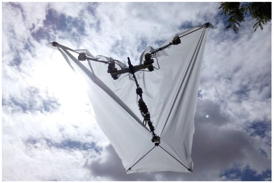
Figure 1.
Prototype of winged aerial manipulation robot with dual arm and tail.
In our previous work [7], we developed an initial prototype of a small-scale compliant dual arm and tail in the context of the ERC GRIFFIN Project [6], using Pololu micro-motors and a customized electronics instead of the Herkulex smart servos employed in the lightweight and compliant dual arm aerial manipulators developed for multirotors [22]. This technological solution was adopted due to the need to reduce the weight of the arms by one order of magnitude with respect to our previous prototypes, reducing their reach from 50 cm (human size) to 25 cm (half-scale) and the weight from 1.5 kg [5] to 0.2 kg [7]. The choice of this scale is also justified by taking into account the biomechanical parameters of bird species with a similar weight and wingspan, collected in Table 1 [23,24].

Table 1.
Biomechanical parameters of some bird species.
The main contribution of this paper is the development and experimental validation of a new morphology of dual arm aerial manipulation robot, illustrated in Figure 1, which uses the arms for manipulating and as morphing wings. The arms, fuselage, and tail of the robot are covered by a light nylon cloth that provides an aerodynamic lift force to be exploited in gliding maneuvers. The dual arm implements the kinematic configuration detailed in [5,22], with 3-DOF (degree of freedom) for end effector positioning (shoulder yaw, shoulder pitch, and elbow pitch), following a modular design approach, based on customized micro-servo actuators, that facilitates the design and assembly of the arms and reduces the wiring with regards to our previous prototype [7]. The paper analyzes, through CFD (computational fluid dynamics) simulation, the aerodynamic wrenches induced over the winged aerial robot in wind tunnel conditions for five illustrative configurations of the arms and tail, identifying the surfaces that allow the control of the rolling-pitching maneuvers. The simulation results provide an estimation of the forces and moments acting over the body frame, whereas the experiments carried out in a test bench using a quadrotor as a wind source validate the proposed concept as well as the manipulation and morphing capabilities of the WAMR. Outdoor flight tests are conducted with a prototype built with conventional servo actuators.
The rest of the paper is organized in the following way. Section 2 presents the design and construction of the winged aerial manipulator, and in Section 3, the kinematics, dynamics and control scheme are described. The aerodynamic surfaces are identified in Section 4, detailing the simulation tools used to analyze the problem. Simulation and experimental results are shown in Section 5, while the conclusions and future work are included in Section 6.
2. Design of Winged Aerial Robot with Dual Arm and Tail
2.1. Concept Design and Intended Applications
As stated in the introduction, this paper is focused on the design and development of a winged aerial manipulator that employs a dual arm system for dexterous manipulation tasks and as a morphing wing mechanism, covering the whole body of the robot with a light nylon cloth to create aerodynamic surfaces (see Figure 1). In this sense, the dual arm and tail can be used to control the aerodynamic wrenches acting over the robot in flight as well as the position of the center of mass by changing its pose and, thus, the trajectory followed during the gliding maneuver [16]. The kinematic configuration of the dual arm (detailed in Section 3) allows the flapping of the wings in a similar way to birds in order to generate a lift force [17], although this is out of the scope of this paper, focused on the gliding while providing dexterous manipulation in perching conditions [7].
The potential applications of winged aerial manipulation robots are determined by their features and capabilities, indicated in Table 2 and compared with respect to the aerial manipulators built with multirotor platforms [5,22]. Some illustrative application examples in which this new kind of aerial robot may be useful include the following:
Table 2.
Benefits and drawbacks of multirotor-based and winged aerial manipulators.
- Search and rescue of injured people in places of difficult access such as mountains or forests, using the arms to take measurements of the temperature, heartbeat, or breath of the person, placing the sensors at the appropriate points.
- Inspection and maintenance of vast infrastructures like power lines, or wind and solar farms, performing typical measurements at points of interest for detecting surface corrosion, leaks, or damaged components.
- Delivery and retrieval of medicines, tools, or small devices, requiring close interaction with humans or the environment without the risk of injury or damage.
- Spread seeds for growing plants, perch on trees for monitoring and tracking bird activities (migration, nesting, breeding), or analyze soil pH.
The inherent safety of the WAMR, associated with its very low weight and the gliding/flapping flying modes, makes this kind of aerial platform especially suitable for operations involving close interaction with people or the environment, avoiding the risk of injuries/damage to multirotors.
2.2. Modular Actuator Design
Motivated by the convenience of simplifying the design and assembling the arms, reducing the wiring with regard to our previous prototype [7], a modular micro-servo actuator was developed based on the Pololu micro-metal gear motors 250:1 (10 g weight, 3.7 kg·cm stall torque) and a customized electronics that integrates a STM32F100 microcontroller and a DRV8833 motor driver, measuring the rotation angle with a Murata SV-01A potentiometer. Figure 2 shows the actuator, weighing 25 g, whose dimensions are 22 × 22 × 35 mm. The motor and the output aluminum shaft are supported by a polymer bearing and the case that covers the motor, supports the electronics, and protects the micro-motor shaft against radial and axial loads. The micro-servos, identified by a unique ID, are connected in a daisy chain using a USART (universal synchronous/asynchronous receiver transmitter) interface for communication with the main controller board at rates of up to 500 Hz, similar to the Herkulex smart servos employed in our previous prototypes [5].
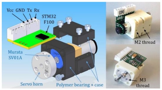
Figure 2.
Customized micro-servo actuator based on Pololu micro-motor.
These actuators allow three control modes:
- Closed-loop position control with the feedback given by the output shaft potentiometer.
- Closed-loop velocity control using the magnetic encoder attached to the motor shaft.
- Current/torque control, acting over the PWM (pulse width modulation) signal of the driver.
The first mode will be applied along with the inverse kinematic model described in Section 3.1 in the realization of manipulation tasks like object grasping or inspection by contact, as well as in the wing-morphing phase for the gliding maneuver. The velocity control results are more appropriate to the generation of flapping patterns with different amplitudes or frequencies, whereas the third mode is intended for operations involving contact forces in quasi-static conditions—for example, applying a pushing force against a surface for installing a device with an adhesive.
2.3. Design of Winged Aerial Manipulation Robot
The study of the anatomy of birds presented in [23] reveals that the structure of the wings can be assimilated to a manipulator with three links: upper arm (humerus), forearm (radius and ulna), and hand (carpometacarpus and digits). This makes possible the application of some design concepts and methodologies derived from the development of lightweight dual arms for aerial manipulation [5]. The winged aerial manipulator developed here follows a modular and bioinspired design approach, building the dual arm and tail with the micro-servo actuators described previously and with a simple frame structure manufactured in aluminum and with 3D printed PLA (polylactic acid) parts. The different structures of the arms can be seen in Figure 3, and their masses are indicated in Table 3. The dual arm manipulator implements the kinematic configuration considered in [22], with three joints for end effector positioning (shoulder yaw, shoulder pitch, and elbow pitch), reducing the scale by half with regard to the human arm (250 mm reach), as motivated in [7]. Note that in this model, unlike our previous prototype, the joints are stiff in order to simplify the mechanics and reduce the weight (0.4 kg in total).
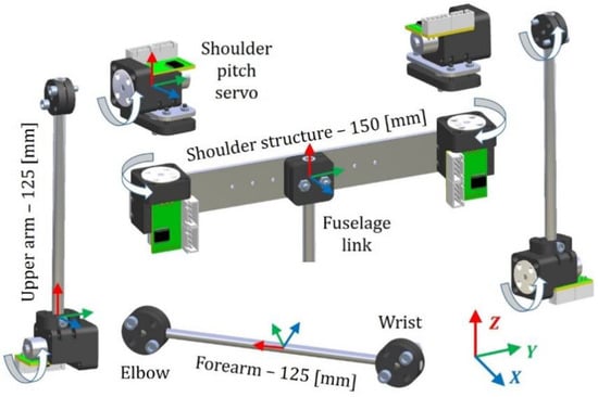
Figure 3.
Rendered view of the structure of the dual arm.
Table 3.
Mass (in (g)) and moment of inertia (in (g·cm2), relative to the center of mass) of the different structures of the winged aerial manipulation robot.
The fuselage link consists of a hollow aluminum tube, 400 mm in length and 6 mm in Ø, attached to the shoulder structure, which supports the tail servo on the other end. The tail mechanism is built with a pair of V-shaped aluminum rods that can be rotated in the pitch angle, allowing the control of the orientation of the WAMR at this angle during the gliding maneuvers, whereas the rotation of the shoulder joints is used to generate lateral aerodynamic wrenches, as will be seen in Section 5.4.
The batteries (2 × 1S, 320 mAh) and control electronics of the aerial robot are located in the fuselage frame. This includes the STM32F0 Nucleo microcontroller board, a BNO055 9-DOF IMU (inertial measurement unit), and an XBee module used as a wireless link with the GCS (ground control station) laptop. The hardware architecture is represented in Figure 4, while in Figure 5, the components are shown. It is interesting to compare this prototype to the compliant dual arm developed in [7], by which the reduction in the wiring due to the modular design approach of the micro-servos is noticeable. The arms provide around 0.15 kg lift load at the elbow joint, with a nominal operation time of around 15 min with the batteries.
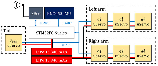
Figure 4.
Hardware architecture of the winged aerial manipulation robot.
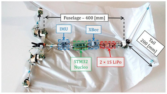
Figure 5.
Components and dimensions of the winged aerial manipulator.
The whole body of the winged aerial robot is covered by a light nylon cloth attached to the forearm and upper arm links, the fuselage tube, and the tail rods to create the aerodynamic surfaces identified in Section 4. The total area is around 0.2 (m2). The cloth is arranged in such a way that it is stretched when the arms adopt the gliding configuration, but it can be folded without affecting the rotation of the joints during the manipulation phases. Since the nylon cloth lacks elasticity, it is necessary to introduce small folds close to the joints to facilitate its accommodation to the adopted pose when acting as a morphing wing.
2.4. Design of Flapping-Wing Aerial Robot
The structure of the winged aerial manipulation robot described in the previous subsection can be extended for building flapping-wing aerial robots using conventional servo actuators like Herkulex [5] or Dynamixel [1,2,3]. This significantly simplifies the development of this kind of platform as these actuators integrate the electronics, communications, and control in a compact and reliable device that can be easily integrated into the frame’s structure. Figure 6 shows a second prototype, constructed from carbon fiber and validated in outdoor flight tests (see Section 5.4), that employs three Herkulex DRS-0101 servos to generate the flapping motion in both semi-wings and control the pitch angle of the tail.
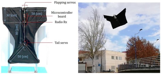
Figure 6.
Winged aerial robot built with Herkulex smart servos.
3. Modeling and Control
3.1. Kinematic Model
As usual in aerial manipulation [5], thee reference frames are considered in the definition of an aerial manipulation task: the Earth fixed frame (inertial), the robot body frame (attached to the IMU), and the manipulator frame {0}. These are represented in Figure 7, also identifying the joints of the arms and the length of the links. The nylon cloth that covers the robot is not represented, for clarity reasons. As indicated before, the dual arm implements the kinematic configuration employed in [22], with three joints for end effector positioning: shoulder yaw at the base (), shoulder pitch (), and elbow pitch (). From now on, superscript will denote the left or right arm, whereas subscript indicates the particular joint in the order defined before, so will denote the rotation angle of the j-th joint of the i-th arm, and is the corresponding joint position vector. The rotation angle of the tail in the pitch angle is denoted by . The axes of are defined as in [5], taking into account that the arms usually operate with the X-axis pointing to the forward direction and the Z-axis pointing upwards (perching conditions), whereas is defined considering the pose adopted while gliding. The position of the winged aerial robot relative to will be denoted as , whereas represents the orientation of the roll, pitch, and yaw angles.
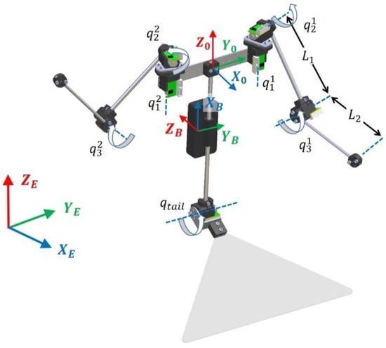
Figure 7.
Kinematic model of the winged aerial manipulator.
The proposed configuration of the arms provides analytical resolution to the forward and inverse kinematics. The position of the tool center point (TCP) and the vector of joint variables are obtained from the mapping and :
where is the two-argument arctangent function. The trajectory control methods based on the inverse kinematics developed in [5] can be applied in this prototype, exploiting the position controller embedded in the micro-servos.
3.2. Dynamic Model
The dynamic model of the winged aerial manipulator can be derived from the Lagrangian and the generalized equations of the forces and torques.
where is the Lagrangian, and are the kinetic and the potential energies, respectively, and ξ and are the vectors of generalized coordinates and forces acting over the robot:
Here, and are the wrenches acting over the robot’s body due to the aerodynamic forces and the moments induced by the arms. The dynamic model can be expressed in the usual compact matrix form:
where represents the generalized inertia matrix, denotes the centrifugal and Coriolis terms, is the gravity term, and models the aerodynamic wrenches acting over the aerial robot, which depends on the orientation and velocity of the body and on the pose of the arms and the tail. The experimental results presented in Section 4.4 and Section 5.3 analyze how the forces and moments induced over the body’s frame can be controlled in terms of the joint angles.
3.3. Control Scheme
In the operation of the winged aerial manipulation robot, two control modes are defined: gliding and manipulating (the transition between both is illustrated in Section 5.1). Figure 8 represents the general control scheme, in which the dual arm task manager and the flight controller blocks act over the left/right arms and the tail servo through the joint references. The micro-servo actuators described in Section 2.2 can be controlled in position with the embedded PID (proportional-integral-derivative), or in torque velocity through the PWM signal [7] with update rates of up to 500 Hz, limited by the daisy chain. The task manager block implements different functionalities, including bimanual object grasping [5], grabbing, perching [16], or contact force control. The flight controller is divided into two layers: the low level attitude controller takes as input the velocity references given by the trajectory controller, along with the state estimation obtained from the sensors and the aerodynamic model given by Equation (6), acting over the joint references to control the aerodynamic surfaces [15], as well as the induced wrenches [14,15,16].
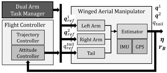
Figure 8.
General control scheme of the winged aerial manipulator.
4. Aerodynamic Analysis
4.1. Identification of Aerodynamic Surfaces
The body of the winged aerial manipulator shown in Figure 1 is completely covered by a light nylon cloth that provides a certain aerodynamic lift, allowing trajectory control during the gliding maneuver, using the tail and the arms for this purpose. In order to estimate the forces and moments acting over the body, a CFD analysis is carried out, considering the geometric model illustrated in Figure 9. This model is parametrized in terms of the link lengths and the joint and tail rotation angles. For simplicity, it is assumed that the surfaces are deformable and adapt to the pose of the arms and the tail, although in practice, the area will be slightly higher to compensate for the folding of the nylon cloth due to the rotation of the joints, as the nylon is not elastic.
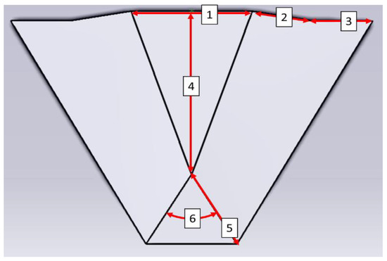
Figure 9.
Surfaces of the winged aerial robot and representative parameters: separation between arms (1), upper arm (2) and forearm (3) link lengths, fuselage length (4), tail length (5), and wide angle (6) of the tail.
4.2. CFD Setup
The CFD analysis is carried out using the ANSYS Fluent software, emulating the conditions of a wind tunnel that measured 6 × 6 m, with a length of 13 m. The winged robot is supposed to be 3 m away from the intake of the wind tunnel, leaving 10 m behind to eliminate undesired aerodynamic effects. Five illustrative configurations of the arms and tail are considered in the results presented in Section 4.4: flat configuration, tail up, tail down, shoulder rotation, and elbow rotation. These are indicated in Table 4. The angle of attack α (AoA) with regard to the wind, that is, the pitch angle θ in the cruise flight configuration, will vary from 0° to 10°. The mesh created for the numerical resolution consists of ~1.5 million tetrahedral elements, with a size of 1 mm over the cloth surface and a growth rate of 1.2 on the space. In this way, the residuals in the velocity are around 10−7, and, for continuity, k and epsilon reach 10−3 in all simulations. With these conditions, each simulation takes around 3 h on an Intel Xeon E5-2620 @2.1 GHz CPU with 128 GB RAM DDR3, with the Windows 10 operating system. Figure 10 shows the vectors involved in the analysis, along with the pressure distribution on the surface.
Table 4.
Kinematic configurations for each case of study: Configuration 1 serves as a reference; Configs. 2 and 3 affect longitudinal maneuvers; Configs. 4 and 5 affect lateral maneuvers.
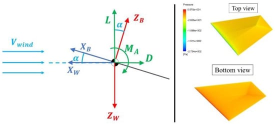
Figure 10.
Vectors considered in the computational fluid dynamics (CFD) analysis (left): wind velocity, angle of attack, lift and drag, aerodynamic moment, body and wind axes. Pressure distribution in the surface of the winged aerial robot (right).
The software solves the discretized Navier–Stokes equations, applying the finite volumes method and the “k-ε Realizable” turbulence model and modeling the fluid as an ideal gas. The boundary conditions are defined as follows: (1) the cloth and the surfaces of the wind tunnel are assimilated to a wall with no slip, (2) the intake of the wind tunnel is an undisturbed air current at 10 m/s speed at ambient pressure and temperature (Pa, and 300 K, respectively), and (3) the outtake is an outlet vent. These values are given for a Reynolds number of around 4 × 10⁵. The results presented in Section 5.3 are obtained using the SIMPLE algorithm for pressure–velocity coupling, computing the solution in less than 2000 iterations. The thin geometry of the cloth complicates the integration of the pressure in the axis, so the accuracy in the estimation of the force in this axis will be lower than in the other axes.
4.3. Trimming
This section calculates the value of the tail angle that should be applied to perform a straight and leveled flight. It is considered that both arms are fully extended, so the cloth is symmetric with regard to the plane and no lateral aerodynamic forces or moments arise. The longitudinal trimming problem involves the longitudinal wrenches, which are demonstrated to be linearly dependent on and the angle of attack. Figure 10 represents the lift , drag , and pitch moment in the wind coordinate system , although the simulation results presented in Section 4.4 are expressed in the body frame for convenience. The dimensionless lift, drag, and the pitching moment are obtained from air density and speed , and the cloth surface and mean chord in the following way:
where , and are the drag, lift, and aerodynamic moment factors. Note that these are linearly dependent on the angle of attack and on the tail deflection angle for the flat configuration, although the value of these parameters may deviate significantly from the linear behavior as the shape of the wings changes with the pose of the arms through the joint angles, and . The CFD simulations presented in the next subsection provide a qualitative analysis of this effect (confirmed later with the experiments shown in Section 5.3), as well as an estimation of the forces and moments induced on the body frame.
The trimming conditions correspond to those values of and that verify the equations:
The solution of Equation for the parameters given in Table 5 is . The parameters of the table were obtained for the prototype described in Section 2.3, assuming that the robot is gliding at a 10 m/s speed, as in the CFD analysis.
Table 5.
Parameters used to solve the trim problem: flight conditions, cloth geometry, and aerodynamic coefficients obtained from CFD.
4.4. CFD Simulation Results
As in [25], this subsection presents simulation results to study the aerodynamic behavior of the winged aerial manipulation robot. Reference [26] also analyses the well-behaved adverse pressure gradient turbulent boundary layer over flat plates through numerical simulation. Quantitative values of the aerodynamic forces and moments induced over the WAMR body are obtained for the five configurations indicated in Table 4, applying the CFD analysis described in Section 4.2. The simulation results are represented in Figure 11. For cases 1 (flat), 2 (tail up), and 3 (tail down), the is a symmetry plane, so the lateral forces and torques ( sliding, rolling, and yawing) are zero. The longitudinal stability and control of the winged aerial robot involve (drag), (lift), and (pitching). As indicated in Section 4.2, is negligible with respect to , so the aerodynamic surface is efficient during the gliding maneuver. For low angles of attack, the behavior of is approximately linear with the pitch angle. According to flight mechanics, the slope of must be negative to ensure longitudinal stability during the gliding. Deflecting the tail upwards increases lift and reduces pitching, and vice versa. This evolution, illustrated on the first row of Figure 11, is proportional to the tail deflection angle, so the tail behaves both as a horizontal stabilizer and as an elevator.
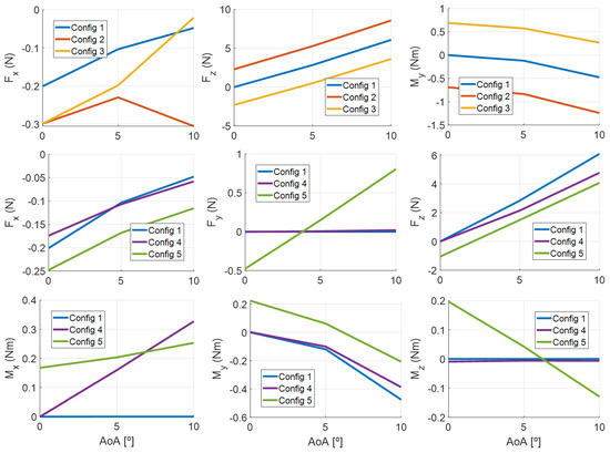
Figure 11.
Forces and moments acting over the body frame for the five poses indicated in Table 2, compared to the flat configuration: tail actuation (first row), elbow, and shoulder rotations (second and third rows).
The lateral directional stability and control is analyzed with Configurations 4 and 5, represented on the second and third rows of Figure 11. If the elbow joint is rotated (Configuration 4), the surface of its semi-wing is reduced, producing less lift than the other, which induces a rolling torque in the aerial platform. In Configuration 5, the wing rotates upwards around the shoulder joint, projecting part of the lift force in the axis, so the center of pressure is displaced vertically. As a result, the platform slides in while rolling and pitching. This behavior is similar to that of a wing with dihedral: a positive dihedral grants lateral stability in case of disturbances in roll or in the presence of lateral wind. These forces and torques arise while the disturbance is present, tending to stabilize the platform in a straight gliding trajectory. As a dihedral angle reduces the lift, the elbow joint can be conveniently adjusted in flight for better lateral stability or to produce more lift.
5. Experimental Results
The following subsections present the experimental results that validate the developed winged aerial manipulation robot. The video of the experiments can be found as supplementary material to this paper.
5.1. Gliding Manipulation Configurations
The winged aerial manipulation robot presented in this paper is intended to conduct bimanual manipulation tasks once the area of interest is reached by gliding. When the platform has landed, the wings are folded and the arms change their configuration, following the sequence of rotations depicted in Figure 12 and Figure 13, representing here the evolution of the joint angles. According to the kinematic model represented in Figure 7, the flying configuration corresponds to the pose (in degrees), whereas the nominal manipulation configuration is given by , that is, the L-shaped pose in which the forearm is rotated 90 degrees. This operation relies on the PID position controller embedded in the micro-servos, generating the joint references with a 6-DOF space navigator mouse. Since the nylon cloth is not elastic enough, this was carefully attached to the body frame, taking into account the deformation caused by the rotation of the shoulder and elbow joints.
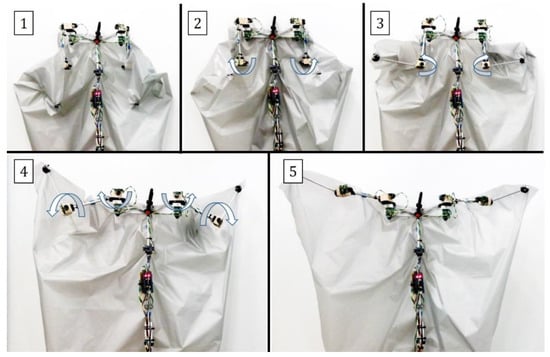
Figure 12.
Sequence of rotations for unfolding the wings: arms stretched (1), elbow (2), shoulder yaw (3), shoulder pitch and elbow pitch (4) joint rotations, flying/gliding pose (5).
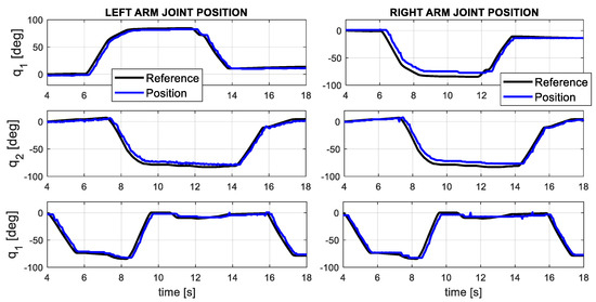
Figure 13.
Evolution of the joint angles of the dual arm during the morphing transition.
5.2. Manipulation Capability
In order to evaluate the possibility of performing manipulation operations with objects like sensor devices or small tools, it is necessary to determine the lift load capacity of the arms in the first place, applying for this purpose the benchmark test described in [27]. The experiment, illustrated in Figure 14, consists of lifting a payload mass attached at the end effector of the arms, rotating the forearm link first and then the upper arm link while the arm is fully stretched. This allows us to estimate the real torque capacity of the micro-servo actuators in the following way:
where is the payload mass, is the gravity constant, and is the link length. The payload in this case was a pair of Herkulex DRS-0402 servos supported by an aluminum bar, weighing 260 g in total. The resulting static torque in the elbow joint is .
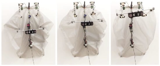
Figure 14.
Sequence of images showing the lift load capacity using the dual arm.
5.3. Evaluation of Gliding Capability
The ability of the winged aerial robot to control the aerodynamic wrenches acting over the body frame using the arms and tail is evaluated qualitatively in a test bench. The airflow generated by a quadrotor will serve to emulate gliding conditions while the aerial robot is suspended from three wires attached to a Rexroth structure. The quadrotor employs four DJI 430 LITE brushless motors and 9 × 4.5” propellers, lifting 1.8 kg at 55% of its capacity. The experiment consisted of generating two manoeuvres with the surfaces identified in Figure 9 (pitching with the tail and rolling with the arms), identifying by visual inspection and through the data given by the IMU the reaction over the body frame. The results and a sequence of images obtained from the video attachment [28] are shown in Figure 15, Figure 16, Figure 17 and Figure 18. As can be seen, the rotation of the tail induces a moment in the pitch angle (Figure 15), whereas the shoulder yaw joint causes a lateral displacement evidenced in the roll (Figure 18). In this case, the oscillations appreciated in the orientation are due to the nylon cables that hold the shoulder structure of the arms.
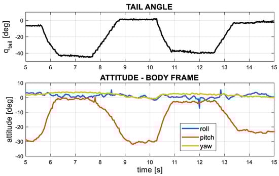
Figure 15.
Variation of the pitch angle due to the moment induced by the tail.
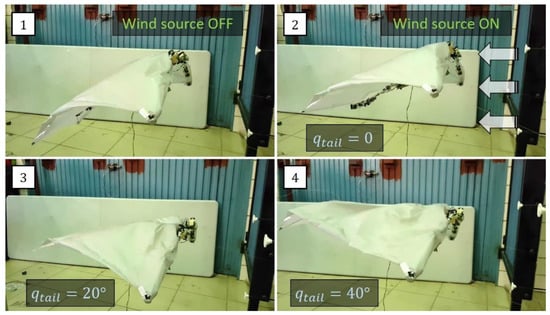
Figure 16.
Testbed experiments with wind source, showing the moment in pitch induced by the tail.
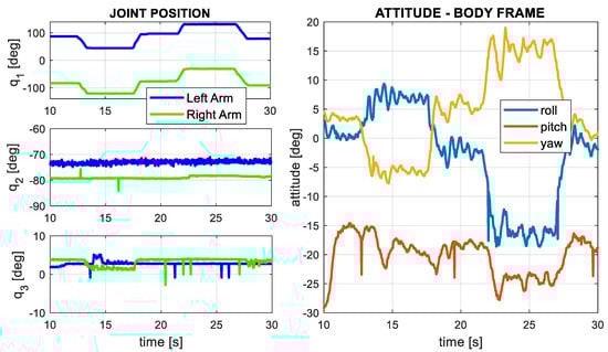
Figure 17.
Joint position of the left and right arms and attitude of the body frame when the arms generate a rolling manoeuvre, inducing a lateral force.
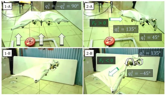
Figure 18.
Testbed experiments with wind source showing the lateral force () induced due to the rotation of the arms around the shoulder yaw joint. Front view with symmetric pose (1-A) and left arm rotation (2-A). Side view with symmetric pose (1-B) and right arm rotation (2-B).
The experiments were repeated outdoors using the structure depicted in Figure 19. The left side of the picture shows the effect of the tail over the body pitch, demonstrating that when the tail rotates upwards, the airflow induces a moment that lifts the body upwards, and vice versa. The sequence of images on the right side illustrates the lateral displacement of the winged aerial robot when the arms change the orientation of the corresponding aerodynamic surfaces.
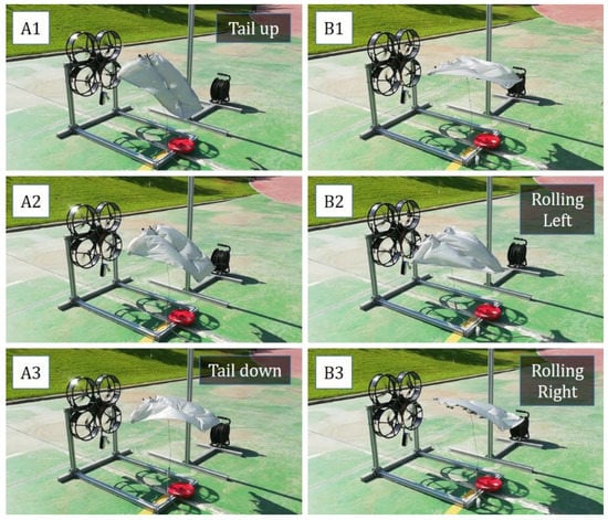
Figure 19.
Wind tests conducted in an outdoor testbed. Tail pitching up (A1), horizontal (A2) and down (A3). Shoulder rotation, flat pose (B1), rolling left (B2) and right (B3).
5.4. Outdoor Flight Tests with Winged Aerial Robot
Preliminary flight tests have been conducted outdoors to validate the design of the winged aerial robot described in Section 2.4, showing in Figure 20 a sequence of images taken from the video attachment [28]. The robot is thrown with an initial velocity to gain lift before the flapping-servos start rotating the wing rods, following a sinusoidal pattern of 30 deg amplitude and 4 Hz frequency. The pilot controls these two parameters, as well as the tail angle, with the sticks of a radio controller. The distance traveled in the 4 s interval (from the launch instant at t = 1.1 s) is 24.8 m, so the mean flight speed is around 6 m/s. The experiments reveal that the lift force generated by the wings and required to keep the aerial robot on flight increases with the flapping frequency, and the relatively high surface of the tail generates significant moments on the body frame that can be exploited for trajectory control and to reduce the flight speed quickly, facilitating in this way a soft landing.
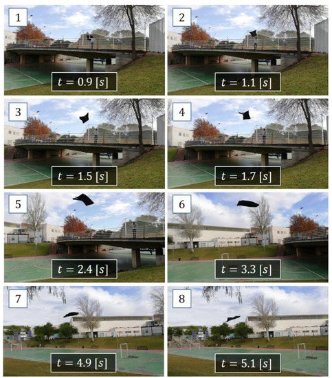
Figure 20.
Sequence of images showing the outdoor flight tests with the winged aerial robot.
6. Conclusions
This paper presented a winged aerial manipulation robot, a new morphology that combines dexterous bimanual manipulation with gliding capability, using the joints of the arms and tail to control the aerodynamic surfaces and, with them, the wrenches acting over the body frame. This design concept is intended to reduce the total weight of the robot, removing the distinction between the aerial platform and the robotic manipulator, as in the case of aerial manipulators built with multirotors. The modular design approach is based on customized micro-servo actuators (25 g weight, 0.2 N·m torque), significantly simplifying the manufacturing of the prototype. The testbed experiments with wind source allowed the evaluation some of the gliding maneuvers that can be conducted with the arms and tail.
In future work, the winged aerial manipulation robot will be enhanced, replacing the aluminum frames with carbon fiber in order to reduce the weight. The elasticity of the cloth should be investigated, as well as the use of higher power actuators to produce lift. The integration of mechanical compliance in the legs or arms is also convenient to protect the robot against impact during the landing or perching transition, allowing the estimation of the torques through the deflection measurement.
Supplementary Materials
The following are available online at https://www.mdpi.com/2076-3417/10/14/4783/s1, Video S1: Winged aerial manipulator with dual arm and tail.
Author Contributions
Conceptualization, A.S., P.G. and A.O.; methodology, A.S.; software, A.S. and M.P.; validation, A.S., M.P. and P.G.; formal analysis, P.G.; investigation, G.H. and A.O.; resources, G.H.; data curation, A.S.; writing—original draft preparation, A.S.; writing—review and editing, G.H.; visualization, G.H.; supervision, A.O.; project administration, A.O.; funding acquisition, A.O. All authors have read and agreed to the published version of the manuscript.
Funding
This work has been partially funded by the European Research Council Advanced Grant GRIFFIN (General compliant aerial Robotic manipulation system Integrating Fixed and Flapping wings to INcrease range and safety), Action 788247, the AERIAL-CORE (H2020-2019-871479) project from the European Commission and the ARM-EXTEND (DPI2017-89790-R) and ARTIC (RTI2018-102224-B-I00) projects, funded by the Spanish Ministerio de Economia, Industria, y Competitividad.
Acknowledgments
The authors want to acknowledge the support of Manuel Perez in the development of the winged aerial manipulator prototype.
Conflicts of Interest
The authors declare no conflict of interest.
References
- Kim, S.; Choi, S.; Kim, H.J. Aerial manipulation using a quadrotor with a two DOF robotic arm. In Proceedings of the 2013 IEEE/RSJ International Conference on Intelligent Robots and Systems, Tokyo, Japan, 3–7 November 2013; pp. 4990–4995. [Google Scholar]
- Ruggiero, F.; Trujillo, M.; Cano, R.; Ascorbe, H.; Viguria, A.; Perez, C.; Lippiello, V.; Ollero, A.; Siciliano, B. A multilayer control for multirotor UAVs equipped with a servo robot arm. In Proceedings of the 2015 IEEE International Conference on Robotics and Automation (ICRA), Seattle, WA, USA, 26–30 May 2015; pp. 4014–4020. [Google Scholar]
- Orsag, M.; Korpela, C.; Bogdan, S.; Oh, P. Valve turning using a dual-arm aerial manipulator. In Proceedings of the 2014 International Conference on Unmanned Aircraft Systems (ICUAS), Orlando, FL, USA, 27–30 May 2014; pp. 836–841. [Google Scholar]
- Ollero, A.; Cortes, J.; Santamaria-Navarro, A.; Soto, M.A.T.; Balachandran, R.; Andrade-Cetto, J.; Rodriguez, A.; Heredia, G.; Franchi, A.; Antonelli, G.; et al. The AEROARMS Project: Aerial Robots with Advanced Manipulation Capabilities for Inspection and Maintenance. IEEE Robot. Autom. Mag. 2018, 25, 12–23. [Google Scholar] [CrossRef]
- Suarez, A. Compliant Aerial Manipulation. Ph.D. Thesis, University of Seville, Sevilla, Spain, 2019. [Google Scholar]
- GRIFFIN ERC Advanced Grant Project. General Compliant Aerial Robotic Manipulation System Integrating Fixed and Flapping Wings to INcrease Range and Safety. Available online: https://griffin-erc-advanced-grant.eu/ (accessed on 10 July 2020).
- Suarez, A.; Perez, M.; Heredia, G.; Ollero, A. Small-Scale Compliant Dual Arm with Tail for Winged Aerial Robots. In Proceedings of the 2019 IEEE/RSJ International Conference on Intelligent Robots and Systems, Macau, China, 4–8 November 2019; pp. 208–214. [Google Scholar]
- Trujillo, M.Á.; Dios, J.R.M.-D.; Martín, C.; Viguria, A.; Ollero, A. Novel Aerial Manipulator for Accurate and Robust Industrial NDT Contact Inspection: A New Tool for the Oil and Gas Inspection Industry. Sensors 2019, 19, 1305. [Google Scholar] [CrossRef] [PubMed]
- Tognon, M.; Chavez, H.A.T.; Gasparin, E.; Sable, Q.; Bicego, D.; Mallet, A.; Lany, M.; Santi, G.; Revaz, B.; Cortés, J.; et al. A Truly-Redundant Aerial Manipulator System with Application to Push-and-Slide Inspection in Industrial Plants. IEEE Robot. Autom. Lett. 2019, 4, 1846–1851. [Google Scholar] [CrossRef]
- Paul, H.; Ono, K.; Ladig, R.; Shimonomura, K. A Multirotor Platform Employing a Three-Axis Vertical Articulated Robotic Arm for Aerial Manipulation Tasks. In Proceedings of the 2018 IEEE/ASME International Conference on Advanced Intelligent Mechatronics (AIM), Auckland, New Zealand, 9–12 July 2018; pp. 478–485. [Google Scholar]
- AERONES. Cleaning Drone. Available online: https://www.youtube.com/watch?v=eBVRQDRY5mY (accessed on 10 July 2020).
- Ryll, M.; Bicego, D.; Franchi, A. Modeling and control of FAST-Hex: A fully-actuated by synchronized-tilting hexarotor. In Proceedings of the 2016 IEEE/RSJ International Conference on Intelligent Robots and Systems (IROS), Daejeon, Korea, 9–14 October 2016; pp. 1689–1694. [Google Scholar]
- Brescianini, D.; D’Andrea, R. Design, modeling and control of an omni-directional aerial vehicle. In Proceedings of the 2016 IEEE International Conference on Robotics and Automation (ICRA), Stockholm, Sweden, 16–21 May 2016; pp. 3261–3266. [Google Scholar]
- Woods, M.I.; Henderson, J.F.; Lock, G.D. Energy requirements for the flight of micro air vehicles. Aeronaut. J. 2001, 105, 135–149. [Google Scholar] [CrossRef]
- Beard, R.W.; Kingston, D.; Quigley, M.; Snyder, D.; Christiansen, R.; Johnson, W.; McLain, T.; Goodrich, M. Autonomous Vehicle Technologies for Small Fixed-Wing UAVs. J. Aerosp. Comput. Information, Commun. 2005, 2, 92–108. [Google Scholar] [CrossRef]
- Paranjape, A.; Kim, J.; Chung, S.-J. Closed-Loop Perching and Spatial Guidance Laws for Bio-Inspired Articulated Wing MAV. In Proceedings of the AIAA Guidance, Navigation, and Control Conference, Minneapolis, MN, USA, 13–16 August 2012; p. 4979. [Google Scholar]
- Bachmann, T. Anatomical, Morphometrical and Biomechanical Studies of Barn Owls and Pigeons’ Wings. Ph.D. Thesis, RTWH Aachen University, Aachenm, Germany, 2011. [Google Scholar]
- Chirarattananon, P.; Chen, Y.; Helbling, E.F.; Ma, K.Y.; Cheng, R.; Wood, R.J. Dynamics and flight control of a flapping-wing robotic insect in the presence of wind gusts. Interface Focus 2017, 7, 20160080. [Google Scholar] [CrossRef] [PubMed]
- Pounds, P.E.I.; Deer, W.; Deer, W. The Safety Rotor—An Electromechanical Rotor Safety System for Drones. IEEE Robot. Autom. Lett. 2018, 3, 2561–2568. [Google Scholar] [CrossRef]
- Ramezani, A.; Shi, X.; Chung, S.-J.; Hutchinson, S. Bat Bot (B2), a biologically inspired flying machine. In Proceedings of the 2016 IEEE International Conference on Robotics and Automation (ICRA), Stockholm, Sweden, 16–21 May 2016; pp. 3219–3226. [Google Scholar]
- FESTO. Bionic Flying Fox. Available online: https://www.festo.com/group/en/cms/13130.htm (accessed on 10 July 2020).
- Suarez, A.; Jimenez-Cano, A.E.; Vega, V.M.; Heredia, G.; Castaño, A.R.; Ollero, A. Design of a lightweight dual arm system for aerial manipulation. Mechatronics 2018, 50, 30–44. [Google Scholar] [CrossRef]
- Viedeler, J.J. Avian Flight; Oxford University Press: Oxford, NY, USA, 2006. [Google Scholar]
- All about Birds. Available online: https://www.allaboutbirds.org (accessed on 10 July 2020).
- Vinuesa, R.; Negi, P.; Atzori, M.; Hanifi, A.; Henningson, D.; Schlatter, P. Turbulent boundary layers around wing sections up to Rec=1,000,000. Int. J. Heat Fluid Flow 2018, 72, 86–99. [Google Scholar] [CrossRef]
- Vinuesa, R.; Örlü, R.; Sanmiguel Vila, C.; Ianiro, A.; Discetti, S.; Schlatter, P. Revisting history effects in adverse-pressure-gradient turbulent boundary layers. Flow Turbul. Combust. 2017, 99, 565–587. [Google Scholar] [CrossRef]
- Suarez, A.; Vega, V.M.; Fernandez, M.J.; Heredia, G.; Ollero, A. Benchmarks for Aerial Manipulation. IEEE Robot. Autom. Lett. 2020, 5, 2650–2657. [Google Scholar] [CrossRef]
- Video of the Experiments. Available online: https://www.youtube.com/watch?v=guwlbkGFcEY (accessed on 10 July 2020).
© 2020 by the authors. Licensee MDPI, Basel, Switzerland. This article is an open access article distributed under the terms and conditions of the Creative Commons Attribution (CC BY) license (http://creativecommons.org/licenses/by/4.0/).