Article

Fabrication of Ceramic Moulds Using Recycled Shell Powder and Sand with Geopolymer Technology in Investment Casting

Institute of Mineral Resources Engineering, National Taipei University of Technology, Taipei 10608, Taiwan
*
Author to whom correspondence should be addressed.
Appl. Sci. 2020, 10(13), 4577; https://doi.org/10.3390/app10134577
Submission received: 1 June 2020 / Revised: 25 June 2020 / Accepted: 29 June 2020 / Published: 1 July 2020
(This article belongs to the Section Environmental Sciences)

Abstract

:
Lost-wax casting, also called precision casting, is the process of casting a duplicate metal sculpture cast an original sculpture. The ceramic shell mould used in lost-wax casting usually consists of several layers formed with fine zircon and granular mullite particles using silica gel as a binder. However, it is a complicated and time-consuming process. Large amounts of waste moulds that need to be disposed and recycled become an environmental concern. In this study, waste shell sand from the recycled mould and calcium carbonate/metakaolin were used as raw materials to prepare geopolymer slurry and coating. The influence of mixing ratio and the SiO2/K2O modulus of the alkali solution on the setting time and green/fired strength were evaluated. Ceramic shells with one to four layers of geopolymer slurry and waste sand sprinkling were fabricated and tested for their permeability and green/fired strength. It was found that geopolymer shells had higher green/fired strength and better permeability than the original zircon/mullite shell. For foundry practice, metal casts were fabricated using recycled ceramic shell moulds with one to four layers of geopolymer coating. All cast results have their dimensions all within tolerance limitation and up to 13 h can be saved for the preparation of shell moulds.

1. Introduction

Investment casting is one of the oldest manufacturing processes. It can produce a cast of complicated shape with high precision and a smooth surface that cannot be achieved with the die casting method. In the process of investment casting, the ceramic mould, known as the investment, is produced by repeating a series of steps—coating, sprinkling, and hardening. These steps are repeated until the investment reaches its required thickness—usually 5 to 15 mm (0.2 to 0.6 in). Investment moulds are left to dry completely, which can take 16 to 48 h. Common refractory materials used to create the investments are: silica, zircon, various aluminum silicates. However, investment casting still has two problems that need to be solved: (1) up to 58 h of drying time is needed for the green ceramic shell after dipping in ceramic slurry [1] and (2) the disposal of waste ceramic shell moulds. In Taiwan, about 1.5 Mt of waste foundry sand from waste shell moulds are produced annually [2] and they are difficult to properly dispose of due to environmental concerns. In order to solve these problems, this study focuses on the recycling and reutilization the waste shell sand to produce a new ceramic shell and shorten the processing time of investment casting using the geopolymer technique.
Geopolymer is a type of inorganic polymer synthesized by polycondensation of AlO4 and SiO4 tetrahedral units in alkali solutions. These tetrahedral units are interlinked alternatively where the charge balancing cations are provided by alkali metal cations. Geopolymer was firstly introduced by Joseph Davidovits in the late 1970s [3]. Because geopolymers have a three-dimensional silicon–oxygen–aluminum structure that contains amorphous to semicrystalline phases [4], they usually exhibit excellent physical and chemical properties such as high mechanical strength, short curing time, excellent chemical and fire resistance, low thermal conductivity and shrinkage [5]. Several researchers have studied using geopolymer binder in the foundry industry in recent years, such as, the influence of the hardening rate of moulding sands [6], lower gases emitted from moulding sands [7], influence of the reclaim additions on the properties of moulding sands [8], lowering the final strength and improving the casting knock-out [9], providing a theoretical and practical overview of the geopolymer binder system [10]. The behaviour of geopolymers at high temperature exposure is dependent entirely on the chemical composition of the binder. The type of alkali ion, Si/Al ratio and crystal structure themselves are the important factors included [11,12,13].
In this study, recycled ceramic shell powder and sand with the addition of calcium carbonate and metakaolin (MK) were used as raw materials to prepare geopolymer slurry and coating for shell production. The ground ceramic shell sand was also used as a sprinkling material along with geopolymer slurry. The viscosity, setting time of geopolymer slurry are evaluated. The green and fired flexural strength of geopolymer shells were also measured to determine the optimum process parameters. For practical application and performance evaluation, ceramic shell moulds made with geopolymer slurry and waste sand sprinkling were tested for their green/fired strength and permeability followed by metal casting and tolerance measurement.

2. Experimental

2.1. Materials

Waste ceramic shell moulds (WS) were obtained from Chips Investment Casting Corporation, New Taipei City, Taiwan. The waste ceramic moulds were crushed and dried to produce shell powder and sand with particle size between 70 μm and 600 μm (D50 at 296.9 μm) and particle size between 16 and 30 mesh, respectively. The particle size of metakaolin (MK) is in the range of 0.5 μm to 52.3 μm with D50 at 5.3 μm; particle size of calcium carbonate (CC) is in the range of 0.3 μm to104.7 μm with D50 at 13.4 μm. The chemical compositions of waste shell sand, metakaolin and calcium carbonate are listed in Table 1. Alkali solutions were prepared by mixing potassium silicate solution (8.3 wt% K2O, 20.8 wt% SiO2) and potassium hydroxide solution (KOH).

2.2. Experimental

2.2.1. Geopolymer Slurry Preparation

Geopolymer slurry was synthesized by mixing 80 wt% of WS powder and 20 wt% of CC/MK mixtures with various ratios as shown in Table 2. The role of CC is to increase the permeability of the ceramic shell after pretreated at high temperature due to decomposed CC and rise porosity. The mixture was then mixed with alkali solution of 0.57, 0.70, and 0.82 SiO2/K2O molar ratio, respectively. According to previous test results, the solid/liquid (S/L) ratios were set at 3.46. After thorough mixing for 10 min, the geopolymer slurry was cast in beam moulds (45 mm × 15 mm × 10 mm). After drying at room temperature for 24 h, the geopolymer specimens were removed from the moulds for green strength test and then sintered at 1200 °C (30 min) for the fired strength test.

2.2.2. Preparation of Ceramic Shell with Geopolymer Slurry

The preparation design of ceramic shells with one to four geopolymer outer layers is shown in Figure 1. The ceramic shell moulds were fabricated by repeating a series of slurry, sprinkling, and hardening. In this study, wax patterns of 170 mm × 40 mm × 10 mm were used to prepare ceramic shells for flexural strength tests. The permeability test has modified the method reported by Zych et al. (2013) [14]. In order to preserve the fine details of the mould, the first layer used only zircon slurry and zircon sand sprinkling, and the second layer used zircon slurry and mullite sand sprinkling. The third to sixth layers coating and sprinkling were prepared with either mullite (original shell) or replaced by geopolymer coating (geopolymer slurry + WS sand sprinkling). As Figure 1 shows, 5L-G0HL specimen means no geopolymer coating, only geopolymer slurry on the surface of the specimen. 3L-G2HL means 2 layers of geopolymer coating and geopolymer slurry on the surface. It was found that 6–8 h is required for every layer of mullite coating and sprinkling, but only 1.5 h was needed for geopolymer coating.
After 24 h of drying, the fully cured shell was dewaxed at 170 °C and split into two pieces for flexural strength. For the fired strength test and permeability test, the green shell specimens were sintered at 1150 °C for an hour before testing. For foundry practice, ceramic shell moulds with 1 to 3 layers of geopolymer coating were fabricated for iron casting using a wax pattern as shown in Figure 2. The tolerance and surface of the casts were measured and carefully examined to evaluate the performance of ceramic shell moulds.

2.3. Tests

The apparent viscosity of the geopolymer slurry was measured using a Brookfield Viscometer (type RVF-100, Brookfield, MA, USA). Setting time was determined with a Vicat needle specified in the ASTM C 191 test procedure. A JSM-6510LV (Tokyo, Japan) scanning electron microscope was used for the test samples’ micrographs. A flexural strength test was conducted based upon the ASTM C 78 procedure. The mechanical property test and permeability test results were averaged from at least five samples for every test. The permeability test device in this study was mainly composed of a vacuum pump, a control system and a differential pressure detector. The principle is that the differential pressure detector was used to contact the surface of the shell mould, and the vacuum pump was used to extract the outer ring of the detector to a vacuum state, and bring a gas into the bottle, and the gas of 1 bar pressure was fixed by the control system. The gas pressure between the detector and the shell mould reduced to 0 bar due to the permeability of the shell mould. We recorded the pressure change value, and calculated the permeability by dividing the pressure relief time with thickness of the ceramic shell mould.

3. Results and Discussion

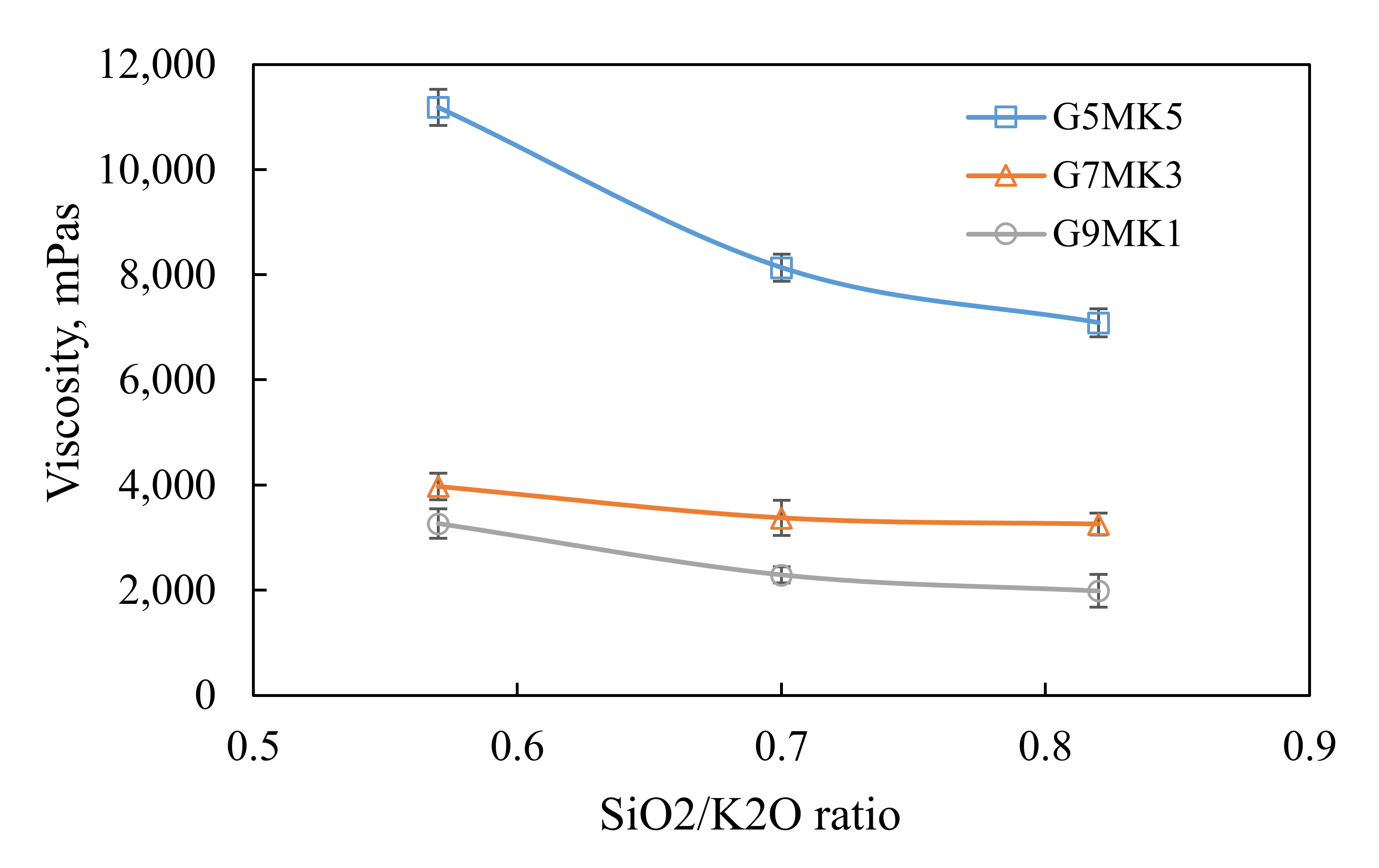
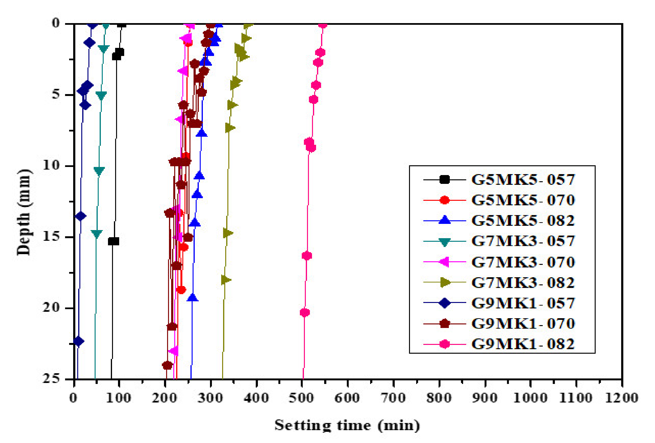
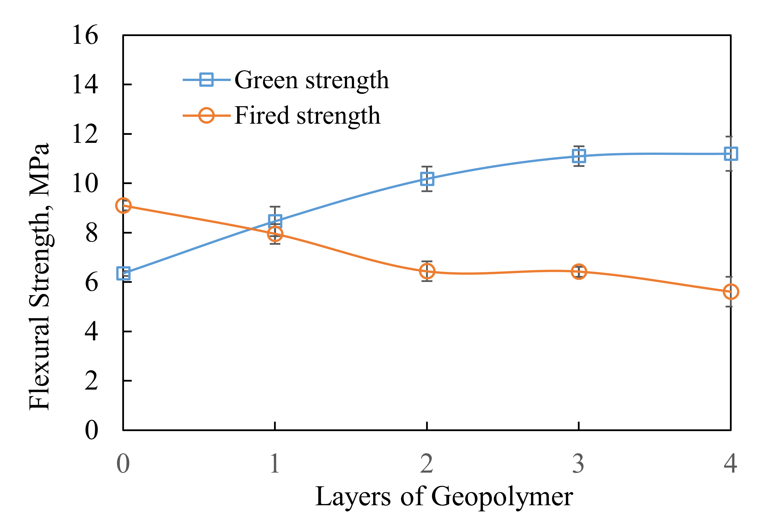
3.1. The Influence of Mixtures and SiO2/K2O Modulus on the Viscosity, Setting Time and Flexural Strength of Geopolymer Slurry

Figure 3 shows the influence of raw material (WS powder, CC and MK) mixing ratios and the SiO2/K2O molar ratio on the apparent viscosity of the geopolymer slurry. It is obvious that specimen G5MK5 has the highest viscosity. As the MK addition decreases from 10% to 2%, the apparent viscosity also decreases from 11,188 mPas to 3270 mPas for geopolymers prepared with 0.57 SiO2/K2O alkali solution. Patankar et al. indicated that the flow of geopolymer concrete increases with an increase in water-to-geopolymer binder ratio by changing the quantity of water [15]. Since the preparation of alkali solutions with various SiO2/K2O ratios is controlled by the concentration of KOH, the higher SiO2/K2O ratio solution (0.82) with low alkalinity is prepared with more water added. Therefore, the SiO2/K2O ratio of the alkali solution may directly affect the viscosity of geopolymer slurry. Particle size may also be another factor that affects the viscosity of geopolymer slurry. Because the particle size of MK (D50 = 5.3 mm) is smaller than CC (D50 = 13.4 mm), MK has a much higher surface area that may result in higher viscosity when the mixture has higher MK content. Keller et al. and Konijn et al. suggested that the increase in particle size may result in a decrease of viscosity [16,17]. Senapati et al. indicated that suspension viscosity of fly ash slurries increases with increasing solid fraction and it decreases with increasing average particle size [18].
Figure 4 shows the setting time of geopolymer slurry prepared with different SiO2/K2O modulus solutions. Specimens G5MK5, G7MK3, and G9MK1 prepared with 0.57 SiO2/K2O alkali solutions have much lower setting time (45–100 min) than those made with 0.70 (250–300 min) and 0.82 (300–520 min) SiO2/K2O alkali solutions. This is because the lower SiO2/K2O modulus solution has higher alkalinity that can dissolve considerable aluminosilicates and form more geopolymer precursors for geopolymeric reaction [19]. The lower alkalinity solutions (0.7 and 0.82 SiO2/K2O molar ratio) leached insufficient Si4+ and Al3+ ions from the WS powder and metakaolin [2,19], and results in low concentration of silicate and aluminate monomers anions during geopolymeric reaction. The long setting time for geopolymer mixtures made with higher SiO2/K2O alkali solutions can also be caused by the higher water content of the solution owing to longer dehydration during the condensation process. For G5MK5 geopolymer made with 0.70 and 0.82 SiO2/K2O alkali solutions also have shorter setting time than those prepared with G7MK3 and G9MK1 mixtures. This result can be attributed to the higher MK content in the G5MK5 mixture, which is considered as a suitable precursor for geopolymeric reaction [20]. If the geopolymer can be used for ceramic shell as binder, the shorter setting time also means faster ceramic shell preparation.
Figure 5 shows the green strength of geopolymer slurries prepared with different mixtures and SiO2/K2O modulus solutions. It is clear that the G5MK5 has flexural strength of about 2–3 MPa higher than G7MK3 and G9MK1. Because MK is considered as a suitable precursor for geopolymeric reaction, the higher MK content can provide more alumino-silicate source to synthesize geopolymer [20]. Several researches have indicated that the geopolymer of metakaolin activation with alkali solution is an amorphous cementitious material [21,22,23] with good mechanical properties [24]. Because G9MK1 geopolymer only contents 2% MK in the mixture, there are insufficient Al and Si ions dissolved from MK to form silico-aluminate structure, and thus, results in the decrease of flexural strength. For G5MK5 and G7MK7 samples, the flexural strength increase from 5.2 MPa to 5.7 MPa and 2.4 MPa to 4.1 MPa, respectively, as the SiO2/K2O modulus of alkali solution increases from 0.57 to 0.82. It is well known that the activation of metakaolin by alkali solution can form AlO4 and SiO4 tetrahedral units [25]. During the condensation of tetrahedral aluminum-silicate units, alkali metal ions (Na+ or K+) will be needed to balance the charge associated with tetrahedral Al [26]. Therefore, the lower concentration of K+ ions in the higher SiO2/K2O modulus solution can better form the 3-D alumino-silicate structure [27].
Figure 6 shows the fired flexural strength of geopolymer slurries after sintering at 1200 °C for 30 min. The fired strength of geopolymer slurries generally has higher flexural strength than those without sintering process, as shown in Figure 4. This is because the semicrystalline behaviour of geopolymer will change into crystalline ceramic phases upon heating [28]. At sintering temperature, the formation of the liquid phase produces joining of the particles and reduction of the porosity and result in the improvement of flexural strength [29]. The fired strength of G5MK5 prepared with 0.57–0.82 SiO2/K2O solutions are higher than G7MK3 and G9MK1 geopolymer slurries due to higher metakaolin content. According to the study conducted by K. T. Chang [30], the porosity of a sintered geopolymer binder is directly related to the calcium carbonate content in the original mixture. The fired strength reduction of the ceramic shell is believed to be due to the outgassing of CO2 through the thermal decomposition process, and thus increases the porosity of the shell.
Figure 7 shows the morphologies of unheated and sintered geopolymers prepared with a 0.57 SiO2/K2O alkali solution. Generally, sintered geopolymer slurries have a much denser surface than that of unheated geopolymer slurries for each individual CC and MK mixing ratio. For the green specimens, no obvious cementing can be observed and a loose and porous structure with clear particle interface can be clearly identified. However, the green G5MK5 exhibits a denser surface with less fractures than that of the G7MK3 and G9MK1 specimens. This is believed to be due to the high MK content that results in high degree geopolymeric reaction. For sintered specimens, particle interface disappears, and cementing surface can be observed. These dense surfaces shown in Figure 7d–f can be attributed to the liquid phase produced at a temperature higher than 900 °C joining particles and forming cementing surfaces, as shown in Figure 7a–c. Bell et al. indicated that the structural change of MK-based geopolymer at a temperature above 850 °C is attributed primarily to viscous sintering [31]. Bell et al. also observed an exothermal due to leucite crystallization from a sol-gel-based precursor over the range of approximately 1000–1200 °C [31]. The crystallization of geopolymer gel should also exist in sintered specimens and results in porosity reduction during the crystallization process.

3.2. Strength and Permeability of Geopolymer Ceramic Shell

For flexural strength and permeability tests, geopolymer ceramic shells of are prepared with six layers of coating and sprinkling using a wax pattern of 170 mm × 40 mm × 10 mm. After dewaxing, two ceramic shell plates can be produced for every wax pattern. The first layer uses only zircon slurry and zircon sand sprinkling and the second layer uses zircon slurry and mullite sand sprinkling. For the third to sixth layer of the ceramic shell, the original four layers of mullite coating and sprinkling are replaced with one to four layers of geopolymer slurry (G5MK5 and 0.57 SiO2/K2O alkali solution) and WS sand sprinkling, as shown in Figure 1.
Figure 8 shows the green and fired strength of the ceramic shell specimens made with various geopolymer coating layers. The flexural strength of the specimens increases from 8.46 MPa to 11.2 MPa as the number of geopolymer coating layer increases from one to four layers. The flexural strength of the ceramic shell prepared with original mullite coating and sprinkling can only reach 6.35 MPa. The flexural strength improvement can be attributed to the formation of a geopolymer gel that cements the WS sand and forms a denser matrix. The more geopolymer coating layers applied to the ceramic shell specimens, the higher the flexural strength obtained. On the contrary, the fired strength (sintered at 1125 °C for 30 min) of ceramic shell specimens decrease from 9.1 MPa to 5.61 MPa as the geopolymer coating layers increase from none to four layers, as shown in Figure 7. The decrease of flexural strength is due to the outgassing of CO2 during CaCO3 (CC) decomposition, and thus increases the porosity of the ceramic shell. Halikia et al. indicated that the decomposition of CaCO3 takes place between 635 °C and 865 °C and accompanies outgassing of CO2 [32]. According to Chang’s study, about 5.5% weight loss was observed at 825 °C in a CaCO3 thermal analysis [30]. Therefore, ceramic shell specimens with more geopolymer coating layers have lower fired flexural strength reached around 6 MPa.
Permeability of the ceramic shell is required to promptly evacuate air and other entrapped gases during metal filling (the method to determine hot permeability and strength of ceramic shell moulds [14]). Ceramic shells with low permeability may entrap the air, and thus, casting defects occur. For permeability measurement, the ceramic shell specimen was fixed and sealed to a chamber that has a constant airflow at 1 bar pressure. After turning off the airflow, the pressure inside the chamber and the time were recorded until the ambient pressure was reached. The effect per unit of mould shell thickness on the time required for the pressure to drop from 1 bar to 0 bar is shown in Figure 9. The experimental results show that as the number of replacement layers was replaced by only the outside half layer (5L-G0HL) to three and a half layers (2L-G3HL), the time required for the pressure drop from 1 bar to 0 bar for a certain thickness of mould shell had a shorter trend and the same trend as the pressure drop time. The high permeability of ceramic shells with geopolymer coating is attributed to the decomposition of CaCO3 that increases the porosity of the specimen. Since the geopolymer coating has better permeability, the more layers it replaced, the shorter the pressure relief time required, and the better the permeability.

3.3. Casting Practice of Geopolymer Shell Mould and Tolerance Evaluation

The casting practice was carried out in a foundry located in New Taipei City, Taiwan. The wax pattern (Figure 2) was used to prepared ceramic shell moulds with a various number of geopolymer slurries and WS sand sprinkling, as listed in Figure 1. The ceramic shell moulds were steam dewaxed at 170 °C to melt out and drain the wax. After dewaxing, ceramic shell moulds were then preheated at 1150 °C for an hour. Melted iron at 1608 °C was poured into the shell mould. After cool down, casts were removed for tolerance measurement and surface examination.
The dimension measurements of the casts are shown in Table 3. It shows the dimension change of castings. It can be found that the surface of the casts made with ceramic shell (5L-G0HL, 4L-G1HL, and 3L-G2HL) of one to three layers of geopolymer coating are as smooth as the cast made with original ceramic shell mould (5HL). The ceramic shell with four layers of geopolymer coating (2L-G3HL) broke down during the iron casting and resulted in leaking of melted iron. This was probably caused by the fire strength being too low. When considering the precision of the casts, all casts made with 5L-G0HL, 4L-G1HL and 3L-G2HL ceramic shell have the cast dimensions within the required tolerance limitation.

3.4. Evaluation of Drying Time Saving for Preparation Shell Moulds

The drying time was calculated from the time required to dip the first layer of slurry to the fifth layer of slurry. Since the drying time of the sixth layer of sealing slurry was 24 h, this time was not included in the calculation. From Table 4, it can be seen that in an investment casting plant, generally, the drying process needs 34 h (5HL). As the ceramic shell with three layers of geopolymer coating (2L-G3HL) failed and leaked melted iron, the best replacement layers for making the ceramic shell were two and half layers (3L-G2HL) and up to 13 h drying time can be saved for the fabrication shell moulds. If the preparation time of ceramic shell mould becomes a major concern, more than 13 h can be saved for the preparation of shell mould with three layers of geopolymer slurry and WS sand sprinkling.

4. Conclusions

Geopolymer slurry prepared with 0.57 SiO2/K2O alkali solutions have shorter setting times due to the higher alkalinity that can dissolve considerable aluminosilicates and form more geopolymer precursors for geopolymeric reaction. The shorter setting time also means faster ceramic shell preparation. It is clear that because MK is considered as a suitable precursor for geopolymeric reaction, the specimen prepared with higher MK content has green strength about 2–3 MPa higher than lower MK content geopolymers. The fired strength of geopolymers generally is higher than the green strength of geopolymer because the semicrystalline behaviour of geopolymer will change into crystalline ceramic phases upon heating.
The ceramic shell specimens prepared with one to four layers of geopolymer slurries and WS sand sprinkling have higher green and fired strength than the original ceramic shell specimen. Due to the decomposition of CaCO3, the fired strength of ceramic shell specimens decreases as the geopolymer coating layer increase from none to four layers but the permeability can be increased.
The ceramic shell moulds prepared with a geopolymer coating were successfully used in foundry practice. All casts fabricated using ceramic shells have their dimensions all within required tolerance limitation. It is estimated that up to 13 h can be saved for the preparation shell mould with three layers of geopolymer slurries and WS sand sprinkling. It is potentially feasible to use recycled waste shell powder, sand and the geopolymer technology in the investment casting process.

Author Contributions

Conceptualization, T.-W.C.; methodology, T.-W.C. and W.-H.L.; investigation, W.-H.L. and Y.-F.W.; data curation, W.-H.L. and Y.-F.W.; writing—original draft preparation, Y.-C.D.; writing—review and editing, T.-W.C. and Y.-C.D.; supervision, T.-W.C. All authors have read and agreed to the published version of the manuscript.

Funding

This research received no external funding.

Conflicts of Interest

The authors declare no conflict of interest.

References

  1. Jones, S.; Jolly, M.R.; Lewis, K. Development of techniques for predicting ceramic shell properties for investment casting. Br. Ceram. Trans. 2002, 101, 106–113. [Google Scholar] [CrossRef]
  2. Lin, K.L.; Cheng, C.J.; Cheng, A.; Chao, S.J. Study on recycled waste foundry sand as raw materials of cement additives. Sustain. Environ. Res. 2012, 22, 91–97. [Google Scholar]
  3. Xu, H.; Van Deventer, J.S.J. The geopolymerisation of alumino-silicate minerals. Int. J. Miner. Process. 2000, 59, 247–266. [Google Scholar] [CrossRef] [Green Version]
  4. Davisovits, J. Geopolymer Chemistry and Applications, 3rd ed.; Institute Géopolymère, Geopolymer Institute: Saint-Quentin, France, 2011. [Google Scholar]
  5. Li, Q.; Xu, H.; Li, F.; Li, P.; Shen, L.; Zhai, J.P. Synthesis of geopolymer composites from blends of CFBC fly and bottom ashes. Fuel 2012, 97, 366–372. [Google Scholar] [CrossRef]
  6. Holtzer, M.; Drozyński, D.; Bobrowski, A.; Plaza, W. Influence of binding rates on strength properties of moulding sands with the geopol binder. Arch. Foundry Eng. 2014, 14, 37–40. [Google Scholar] [CrossRef]
  7. Bobrowski, A.; Holtzer, M.; Zymankowska-Kumon, S.; Dańko, R. Harmfulness assessment of moulding sands with a geopolymer binder and a new hardener, in an aspect of the emission of substances from the BTEX group. Arch. Metall. Mater. 2015, 60, 341–344. [Google Scholar] [CrossRef]
  8. Drozyński, D.; Bobrowski, A.; Holtzer, M. Influence of the reclaim addition on properties of moulding sands with the geopol binder. Arch. Foundry Eng. 2015, 15, 138–142. [Google Scholar] [CrossRef] [Green Version]
  9. Bobrowski, A.; Drozyhski, D.; Grabowska, B.; Kaczmarska, K. Easy knock-out moulding and core sands-The future for metal casting. Foundry Trade J. Int. 2019, 193, 278–281. [Google Scholar]
  10. Vykoukal, M.; Burian, A.; Přerovská, M. GEOPOL®. The innovated environment friendly inorganic binder system. Arch. Foundry Eng. 2019, 19, 109–116. [Google Scholar]
  11. Zivica, V.M.; Palou, T.; Bágel, T.I.L. High strength metahalloysite based geopolymer. Compos. Part B-Eng. 2014, 57, 155–165. [Google Scholar] [CrossRef]
  12. Yahya, Z.; Abdullah, M.M.A.; Hussin, K.; Ismai, K.N.; Sandu, A.V.; Vizureanu, P.; Abd Razak, P.R. Chemical and Physical Characterization of Boiler Ash from Palm Oil Industry Waste for Geopolymer Composite. Rev. Chim. (Buchar.) 2013, 64, 1408–1412. [Google Scholar]
  13. Ahmad, R.; Abdullah, M.M.A.B.; Hussin, K.; Sandu, A.V.; Binhussain, M.; Jaya, N.A. Processing and properties of polymer filled geopolymer ceramics fabricated via powder metallurgy method: A review. Rev. Adv. Mater. Sci. 2016, 44, 26–32. [Google Scholar]
  14. Zych, J.; Kolczyk, J.; Snopkiewicz, T. New Investigation Method of the Permeability of Ceramic Moulds Applied in the Investment Casting Technology. Arch. Foundry Eng. 2013, 13, 107–112. [Google Scholar] [CrossRef] [Green Version]
  15. Patankar, S.V.; Jamkar, S.S.; Ghuga, Y.M. Effect of water-to-geopolymer binder ratio on the production of fly ash based geopolymer concrete. Int. J. Adv. Technol. Civ. Eng. 2013, 2, 79–83. [Google Scholar]
  16. Keller, D.S.; Keller, D.V., Jr. The effect of particle size distribution on the antithixotropic and shear thickening properties of coal–water dispersions. J. Rheol. 1991, 35, 1583–1607. [Google Scholar] [CrossRef]
  17. Konijn, B.J.; Sanderink, O.B.J.; Kruyt, N.P. Experimental study of the viscosity of suspensions: Effect of solid fraction, particle size and suspending liquid. Powder Technol. 2014, 266, 61–69. [Google Scholar] [CrossRef]
  18. Senapati, P.K.; Mishra, B.K.; Parida, A. Modeling of viscosity for power plant ash slurry at higher concentrations: Effect of solids volume fraction, particle size and hydrodynamic interactions. Powder Technol. 2010, 197, 1–8. [Google Scholar] [CrossRef]
  19. Gao, K.; Lin, K.L.; Wang, D.Y.; Hwang, C.L.; Shiu, H.S.; Chang, Y.M.; Cheng, T.W. Effects SiO2/Na2O molar ratio on mechanical properties and the microstructure of nano-SiO2 metakaolin-based geopolymers. Constr. Build. Mater. 2014, 52, 503–510. [Google Scholar] [CrossRef]
  20. Duxson, P.; Fernández-Jiménez, A.; Provis, J.L.; Lukey, A.; Palomo, G.C.; van Deventer, J.S.J. Geopolymer technology: The current state of the art. J. Mater. Sci. 2007, 42, 2917–2933. [Google Scholar] [CrossRef]
  21. Granizo, M.L.; Blanco, M.T. Alkaline activation of metakaolin. J. Therm. Anal. 1998, 52, 957–965. [Google Scholar] [CrossRef]
  22. Singh, P.S.; Trigg, M.; Burgar, I.; Barstow, T. Geopolymer formation processes at room temperature studied by 29Si and 27Al MASNMR. Mater. Sci. Eng. A 2005, 396, 392–402. [Google Scholar] [CrossRef]
  23. Granizo, M.L.; Alonso, S.; Blanco-Varela, M.T.; Palomo, A. Alkaline Activation of Metakaolin: Effect of Calcium Hydroxide in the Products of Reaction. J. Am. Ceram. Soc. 2002, 85, 225–231. [Google Scholar] [CrossRef]
  24. Granizo, M.L.; Blanco, M.T.; Puertas, F.; Palomo, A. Alkaline activation of metacaolin: Influence of synthesis parameters. In Proceedings of the Tenth International Congress on Chemistry of Cement, Goteborg, Sweden, 2–6 June 1997. [Google Scholar]
  25. Lecomte, I.; Henrist, C.; Liégeoisa, M.; Maserib, F.; Rulmonta, A.; Clootsa, R. (Micro)-structural comparison between geopolymers, alkali-activated slag cement and Portland cement. J. Eur. Ceram. Soc. 2006, 26, 3789–3797. [Google Scholar] [CrossRef]
  26. Feng, D.; Provis, J.L.; van Deventer, J.S.J. Thermal activation of albite for the synthesis of one-part mix geopolymers. J. Am. Ceram. Soc. 2012, 95, 565–572. [Google Scholar] [CrossRef]
  27. Pimraksaa, K.; Chindaprasirt, P.; Rungchet, A.; Sagoe-Crentsil, K.; Sato, T. Lightweight geopolymer made of highly porous siliceous materials with various Na2O/Al2O3 and SiO2/Al2O3 ratios. Mat. Sci. Eng. A 2011, 528, 6616–6623. [Google Scholar] [CrossRef]
  28. Bell, J.L.; Driemeyer, P.E.; Kriven, W.M. Formation of Ceramics from Metakaolin-Based Geopolymers: Part I—Cs-Based Geopolymer. J. Am. Ceram. Soc. 2009, 92, 1–8. [Google Scholar] [CrossRef]
  29. Jonghe, L.C.D.; Rahaman, M.N. Sintering of Ceramics. In Handbook of Advanced Ceramics; Elsevier Inc.: Philadelphia, PA, USA, 2013. [Google Scholar]
  30. Chang, K.T. A Study of Carbonate Mineral Powders Additives on the Collapsibility of Ceramic Shell Mould for Investment Casting. Master’s Thesis, National Taipei University of Technology, Taipei, Taiwan, 2009. [Google Scholar]
  31. Bell, J.L.; Driemeyer, P.E.; Kriven, W.M. Formation of Ceramics from Metakaolin-Based Geopolymers. Part II: K-Based Geopolymer. J. Am. Ceram. Soc. 2009, 92, 607–615. [Google Scholar] [CrossRef]
  32. Halikia, I.; Zoumpoulakis, L.; Christodoulou, E.; Prattis, D. Kinetic study of the thermal decomposition of calcium carbonate by isothermal methods of analysis. Eur. J. Miner. Process. Environ. Prot. 2001, 1, 89–102. [Google Scholar]
Figure 1. Experimental design of ceramic shell mould preparation (GP slurry: geopolymer slurry).
Applsci 10 04577 g001
Figure 2. Wax pattern used for casting practice. A: length; B: width; C: height.
Applsci 10 04577 g002
Figure 3. The apparent viscosity of geopolymer slurry.
Applsci 10 04577 g003
Figure 4. Setting time of geopolymer slurry prepared with different SiO2/K2O molar ratio solutions.
Applsci 10 04577 g004
Figure 5. Green flexural strength of geopolymer slurry.
Applsci 10 04577 g005
Figure 6. Flexural strength of geopolymer slurry after sintering at 1200 °C.
Applsci 10 04577 g006
Figure 7. Scanning electron microscopy (SEM) micrograph of different carbonate/metakaolin ratios of geopolymer before (ac) and after (df) sintering at 1200 °C.
Applsci 10 04577 g007
Figure 8. Flexural strength of shell mould at room temperature and after sintering at 1125 °C.
Applsci 10 04577 g008
Figure 9. Permeability test of shell mould after sintering at 1125 °C.
Applsci 10 04577 g009
Table 1. Chemical compositions of waste ceramic shell, metakaolin and calcium carbonate.
Composition (wt%)SiO2Al2O3ZrO2CaOOthersIgnition Loss
Waste shell powder48.921.728.9N.D.0.5N.D.
Metakaolin54.739.8N.D.N.D.3.61.9
Calcium Carbonate2.21.4N.D.56.81.138.5
N.D.: None detected.
Table 2. Geopolymer slurry preparation design.
SpecimensWaste Shell Powder (wt%)Calcium Carbonate (wt%)Metakaolin (wt%)SiO2/K2O
Molar Ratio
Solid/Liquid Ratio
G5MK58010100.573.46
G7MK31460.70
G9MK11820.82
Table 3. Dimensions and tolerance of casts.
Dimensions, mmWax Pattern5HL5L-G0HL4L-G1HL3L-G2HL2L-G3HL
A172.5 ± 0.9172.2 ± 0.1172.1 ± 0.2172.2 ± 0.1172.6 ± 0.1-
B38.6 ± 0.438.7 ± 0.138.8 ± 0.238.8 ± 0.138.6 ± 0.1-
C35.9 ± 0.435.6 ± 0.135.7 ± 0.235.7 ± 0.235.9 ± 0.1-
Table 4. The effect of geopolymer coating substitution layers on preparation ceramic shell mould drying and time-saving.
Specimens5HL5L-G0HL4L-G1HL3L-G2HL2L-G3HL
Drying Time (h)343427.52114.5
Saving Time (h)-06.51319.5

