Article

An Enhanced Precoder for Multi User Multiple-Input Multiple-Output Downlink Systems

1
Department of Information and Communication Engineering, Sejong University, Seoul 05006, Korea
2
Department of Computer Engineering, Sejong University, Seoul 05006, Korea
*
Author to whom correspondence should be addressed.
Appl. Sci. 2020, 10(13), 4547; https://doi.org/10.3390/app10134547
Submission received: 9 June 2020 / Revised: 26 June 2020 / Accepted: 27 June 2020 / Published: 30 June 2020
(This article belongs to the Special Issue Multi-Channel and Multi-Agent Signal Processing)

Abstract

:
Recently, as the demand for data rate of users has increased, wireless communication systems have aimed to offer high throughput. For this reason, various techniques which guarantee high performance have been invented, such as massive multiple-input multiple-output (MIMO). However, the implementation of huge base station (BS) antenna array and decrease of reliability as the number of users increases are chief obstacles. In order to mitigate these problems, this paper proposes an adaptive precoder which provides high throughput and bit error rate (BER) performances to achieve the desired data rate in multi user (MU) MIMO downlink systems which have a practical BS antenna array (up to 16). The proposed scheme is optimized with a modified minimum mean square error (MMSE) criterion in order to improve BER gain and reduce data streams in order to obtain diversity gain at low signal to noise ratio (SNR). It is shown that the BER and throughput performances of the proposed scheme are improved.

1. Introduction

In the future, wireless communication systems will be able to offer various services, such as virtual reality, big data, etc., and large amounts of data will be able to travel over the network. Therefore, the wireless communication system will probably be able to provide multiple users with high reliability and throughput [1]. However, insufficient bandwidth makes the wireless resources scarce. Therefore, the multiple-input multiple-output (MIMO) system is seen as attractive, due to spectral efficiencies and high throughput [2,3,4,5,6,7]. Also, the multi user (MU) MIMO system was invented to provide high capacity for multiple user equipments (UEs) [8,9]. The MU MIMO system applies a concept of space division multiple access (SDMA) [10]. In a co-channel wireless system, each UE generates inter-user interference (IUI) to other UEs. The challenge is to cancel out IUI disrupting wireless communication. Therefore, the base station (BS) estimates channel state information (CSI) and applies a precoding technique, mitigating IUI. The precoding techniques are divided into nonlinear and linear precoding techniques. Nonlinear techniques [11,12,13] that provide high performance are unrealizable due to their high complexity, and linear techniques supply feasible compromises.
The block diagonalization (BD) precoder is a typical linear precoder [14]. BD is well known as a precoder to carry out perfect nulling through singular value decomposition (SVD) operations. In the environment where channel correlation is high, BS technique can eliminate IUI through SVD. For this advantage, an improved BD precoder has been proposed in many previous studies. For instance, the author in [15] proposed low complexity for the BD precoder. However, although the received signal has a benefit of zero IUI, a BD precoder can not guarantee high bit error rate (BER) performance because the noise component is disregarded. Also, the BD precoder spends most of its spatial resources to achieve perfect nulling, and poor diversity gain is obtained. Therefore, a regularized block diagonalization (RBD) precoder and generalized block diagonalization (GBD) precoder have been proposed in [16,17]. The RBD precoder has been considered attractive since many probabilities of performance improvement are provided by considering noise power. For this reason, the author in [18] proposed an improved precoder in terms of capacity performance. However, the RBD precoder still consumes transmit antenna resources to mitigate IUI. On the other hand, the GBD precoder offers additional diversity gain, but is not optimized with minimum mean square error (MMSE) criterion. Consequentially, the GBD scheme cannot achieve additional BER performance. In other words, the RBD precoder provides improved BER performance by mitigating the noise effect, but additional diversity gain is not obtained. On the other hand, the GBD precoder offers diversity gain as the number of transmitted data streams is adjusted, but additional gain for BER performance is not guaranteed. Therefore, the scheme that obtains diversity gain and simultaneously mitigates the noise component is required to meet the increased demand of the throughput.
Many attempts have been made to increase throughput performance in MU MIMO. In fact, the author in [19] proposed a precoder which obtains improvement throughput by combining the BD with non-orthogonal multiple access (NOMA). However, this precoder uses multiple power domains. Therefore, comparison with a conventional precoder which uses a single power domain is not appropriate. Also, this precoder does not obtain maximum throughput in all signal to noise ratios (SNRs). Thus, a precoder that uses a single power domain and maximizes throughput performance is needed.
This paper proposes a modified GBD (MGBD) precoder which provides improved BER gain by satisfying the modified MMSE criteria and additional diversity gain by adopting partial nulling technique. The modified MMSE criteria is designed to minimize the Frobenius norm for non-diagonal components of equivalent channel that causes IUI. The partial nulling scheme obtains diversity gain by utilizing degrees of freedom. The proposed scheme is operated like a GBD precoder which retains some IUIs to increase diversity gain and uses postcoding to eliminate the remaining IUI. Also, the proposed scheme is optimized through the modified MMSE criterion like RBD precoder. Therefore, the MGBD precoder provides improved BER performance compared to the GBD precoder and guarantees higher throughput performance than the RBD precoder in an unfavorable channel state by adjusting the number of streams. Additionally, in order to maximize the throughput performance according to channel state, this paper proposes an adaptive precoder in order to maximize throughput at all SNRs. The adaptive algorithm performs precoding by adjusting the partial nulling subset according to SNR. In other words, this precoder increases the partial nulling space at high SNRs for high throughput and decreases the partial nulling space at low SNRs for improved BER performance. Thus, UEs in MU MIMO downlink system obtain maximum throughput and BER performance.
This paper is organized as follows. Section 2 presents a MU MIMO downlink system model. Section 3 explains conventional precoding schemes, such as RBD, GBD, etc. In Section 4, the MGBD precoder and the adaptive MGBD algorithm are proposed. The simulation results for BER performance and throughput are represented in Section 5. Section 5 also provides computational complexity for MGBD and RBD. Finally, Section 6 gives brief conclusions.

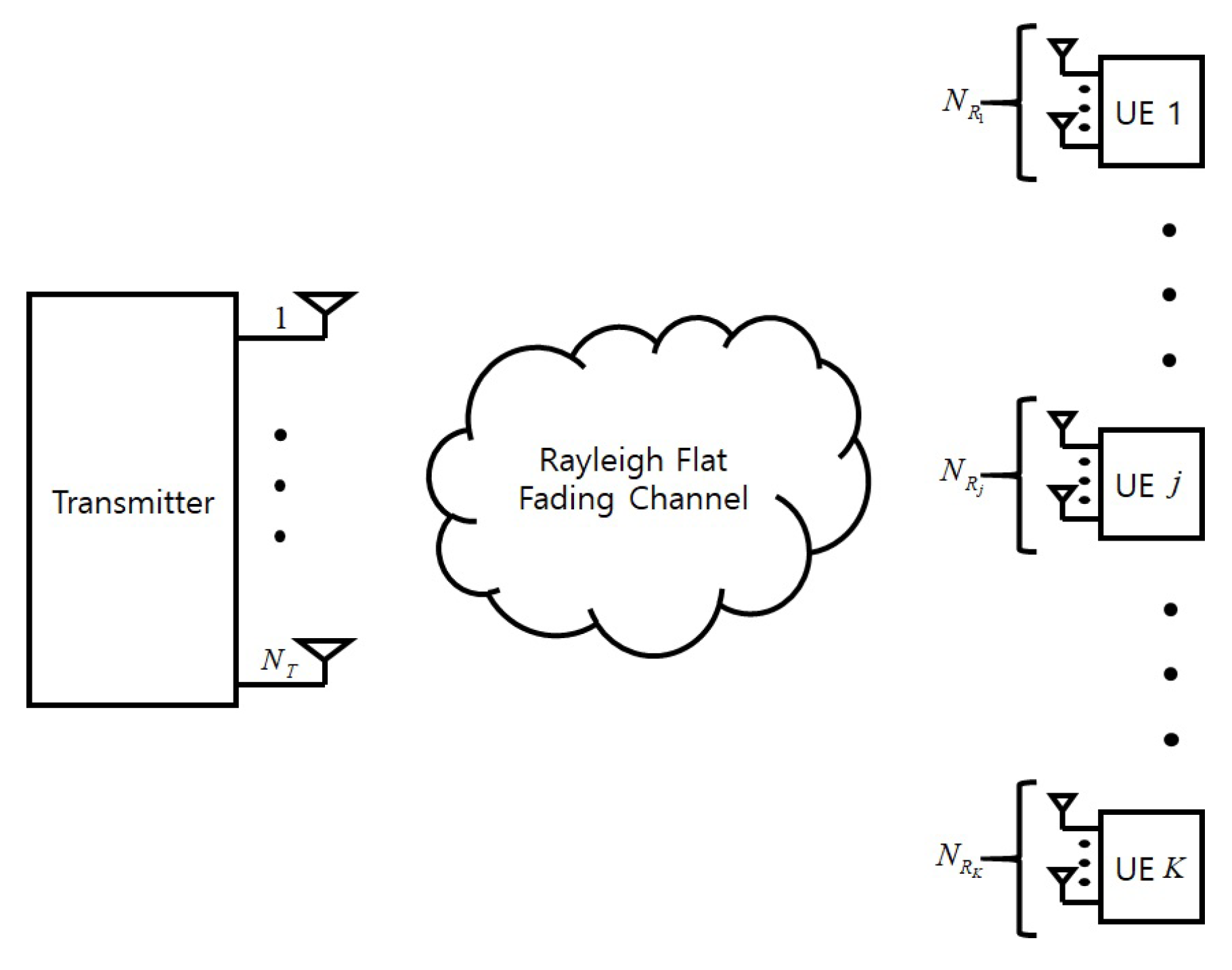
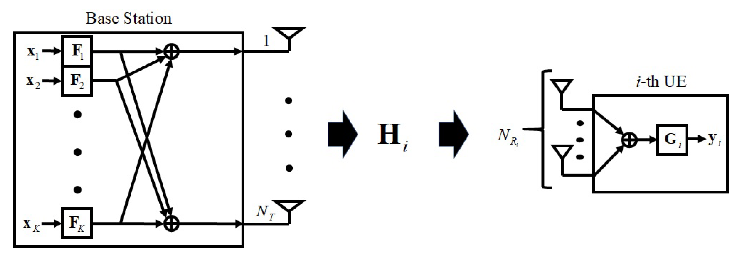
2. Multi User MIMO Downlink System Model

This paper considers a multi user MIMO downlink system model with N T transmit antennas at base station and N R receive antennas, as shown in Figure 1. In this system, the i-th UE has N R i receive antennas and N R = j = 1 K N R j is the total number of receive antennas, where N R N T . The r data streams are transmitted from the base station to K separate UEs via complex Rayleigh flat fading channel. The BS precodes a data signal based on CSI to weaken IUI and transmits the precoded signal. Each UE receives a signal with mitigated IUI and postcodes the received signal to eliminate residual IUI.
In this system model, the received signal vector Y = y 1 T y 2 T y K T T C r × 1 is represented as follows,
Y = G H X ¯ + W ,
where X ¯ C N T × 1 is transmitted signal vector expressed by X ¯ = FX and W = w 1 T w 2 T w K T T C N R × 1 is additive white Gaussian noise (AWGN) vector with independent and identically distributed (i.i.d) components of variance σ W 2 and zero mean. X = x 1 T x 2 T x K T T C r × 1 and F = F 1 T F 2 T F K T T C N T × r are data signal vector which is uniformly distributed with E x i x i H = I r i and precoding matrix. r i is the number of data streams for the i-th UE and r is defined as follows,
r = j = 1 K r j .
Also, it is assumed that E X ¯ 2 = P T and W is independent of transmitted signal X . The joint channel matrix is represented as H = H 1 T H 2 T H K T T C N R × N T . The decoding matrix G C r × N R which is a diagonal matrix of postcoding matrices for all UEs is defined as follows,
G = G 1 0 0 0 G 2 0 0 0 G K .
Then, the received signal of the i-th UE y i can be written as follows,
y i = G i H i F i x i desired signal + H i k = 1 , k i K F k x k IUI signal + w i ,
where G i C r i × N R i , H i C N R i × N T , F i C N T × r i , x i C r i × 1 and w i C N R i × 1 are decoding matrix, Rayleigh flat fading channel matrix, precoding matrix, data signal vector and AWGN vector for the i-th UE respectively. The desired signal is interfered with by the IUI signal. Also, the equivalent single user (SU) model of the i-th UE is represented in Figure 2.

3. Conventional Precoding Schemes

In this section, conventional BD precoder and modified BD precoders are introduced. Before the detailed description, H ˜ i , L and L ˜ i are defined as follows,
H ˜ i = H 1 T H i 1 T H i + 1 T H K T T ,
L = rank ( H ) ,
L ˜ i = rank ( H ˜ i ) .

3.1. Conventional BD Precoder

The typical property for the conventional BD precoder is that IUI signal is completely eliminated by multiplying the precoding matrix by the data signal. Thus, the precoding matrix consists of null space for the channel matrix of other UEs. The conventional BD precoder obtains orthogonal vectors to IUI signal from SVD of H ˜ i . The SVD of H ˜ i is given by,
H ˜ i = U ˜ i Σ ˜ i V ˜ i ( 1 ) V ˜ i ( 0 ) H ,
where U ˜ i C N R N R i × N R N R i and Σ ˜ i C N R N R i × N T are left singular vector matrix and singular value matrix. V ˜ i ( 1 ) C N T × L ˜ i is right singular vector matrix correlated with non zero singular values. V ˜ i ( 0 ) N T × N T L ˜ i is right singular vector matrix correlated with zero singular values. In other worlds, V ˜ i ( 0 ) forms null space for H ˜ i . Then, the conventional BD algorithm uses V ˜ i ( 0 ) as the precoding matrix F i BD . Consequently, IUI signal is completely eliminated and received signal y i can be expressed as follows,
y i = G i H i V ˜ i ( 0 ) x i + w i .
By using the BD precoder, the complex MU MIMO channel turns into parallel SU MIMO channels due to zero IUI. However, the BD algorithm wastes spatial resources by accomplishing perfect nulling and does not obtain additional BER performance by disregarding the noise element.

3.2. RBD Precoder

The RBD scheme which was proposed in [16] was designed to optimize the BD scheme in MMSE criterion. The author in [16] divides the precoding matrix into two parts as follows,
F RBD = γ RBD F MU RBD F SU RBD ,
where γ RBD is scaling factor for RBD, F MU RBD converts MU channel into parallel SU channels guaranteeing MMSE and F SU RBD optimizes performance for the SU channel. The expression for MMSE criterion to obtain F MU RBD is as follows,
F MU RBD = arg min F MU RBD E I N R H F MU RBD X 2 + W 2 γ 2 .
However, the RBD algorithm does not solve Equation (11) to find F MU RBD . Instead, F MU RBD is optimized with modified MMSE criterion that minimizes IUI. The expression for modified MMSE criterion is as follows,
F MU RBD = arg min F MU RBD E i = 1 K H ˜ i F MU , i RBD 2 + W 2 γ 2 .
F MU RBD satisfying Equation (12) is as follows [16,20],
F MU , i RBD = V ˜ i Σ ˜ i T Σ ˜ i + N R σ W 2 P T I N T 1 2 ,
where σ W 2 and P T are noise power and transmit power. The channel H F MU RBD is changed to parallel SU MIMO channels. The SVD for H i F MU , i RBD is defined as H i F MU , i RBD = U ¯ i RBD Σ ¯ i RBD V ¯ i RBD ( 1 ) V ¯ i RBD ( 0 ) H , where U ¯ i RBD , Σ ¯ i RBD , V ¯ i RBD ( 1 ) and V ¯ i RBD ( 0 ) are left singular vector matrix, singular value matrix, right singular vector matrix correlated with non zero singular values and right singular vector matrix correlated with zero singular values. The solution for performance optimization of SU MIMO is as follows [16,20],
F SU , i RBD = V ¯ i RBD ( 1 ) .
Consequently, the i-th UE precoding matrix for RBD is given by,
F RBD = γ RBD V ˜ i Σ ˜ i T Σ ˜ i + N R σ W 2 P T I N T 1 2 V ¯ i RBD ( 1 ) .
Although RBD scheme provides improved performance compared to the BD scheme, the RBD precoder does not offer additional diversity gains, which the BD precoder does.

3.3. GBD Precoder

The key point for the GBD scheme which was proposed in [17] is partial nulling increasing degrees of freedom for a wireless communication system [21]. Therefore, the GBD precoder does not completely eliminate channels for other UEs and the remaining IUI is removed by using postcoding.
The SVD of the i-th UE channel is H i = U i Σ i V i H . GBD precoder selects dominant components for H i as follows,
D i = v i , 1 , v i , 2 , , v i , r i ,
where V i = v i , 1 , v i , 2 , , v i , r i , , v i , N T is right singular vector matix and v i , j is the j-th right singular vector for V i . The matrix of dominant components for other UEs except for the i-th UE is D ˜ i = D 1 , , D i 1 , D i + 1 , , D K . Then, D i is projected onto orhogonal space of D ˜ i by using complementary projection in order to mitigate IUI. The orthogonal vectors with D ˜ i in D i are obtained as follows,
P i = I D ˜ i D ˜ i H D ˜ i 1 D ˜ i H D i ,
where P i is transmit weight matrix and GBD precoder uses P i as precoding matrix F i GBD for the i-th UE.
The GBD precoder suppresses the remaining IUI by utilizing postcoding matrix G GBD . The postcoding matrix G i GBD = [ u i , 1 , u i , 2 , , u i , r i ] H consists of left singular vectors for H i . The IUI elements for the i-th UE are represented as follows,
k = 1 , k i K G k GBD H k F i GBD = k = 1 , k i K I r i 0 Σ k 0 r i Δ ,
where Δ and 0 are a matrix with small-valued elements and a matrix with zero elements. Therefore, the effective channel H eff is given by,
H eff = G 1 GBD H 1 F 1 GBD 0 0 G K GBD H K F K GBD ,
and essentially effective channel G i GBD H i F i GBD is given by,
G i GBD H i F i GBD = [ I r i 0 ] Σ i V i H F i GBD .
Consequently, the number of singular values for desired channel is reduced from N R i to r i and IUI channel is converged to zero.
The GBD scheme increases diversity gain for total systems but is not optimized with MMSE criterion. Therefore, the goal of proposed scheme is that the precoder is optimized with modified MMSE criteria by considering noise entries and provides diversity gain.

4. MGBD Scheme and Adaptive MGBD Scheme

4.1. Modified GBD Precoder

The MGBD precoder transmits a signal with some IUIs to increase degrees of freedom and residual IUI is mitigated by postcoding. Therefore, the postcoding matrix for the proposed scheme consists of left singular vectors for H i . The postcoding matrix G i is given by,
G i = [ u i , 1 , u i , 2 , , u i , r i ] H .
On the other hand, the precoding matrix for the proposed scheme is divided into two parts as follows,
F = γ F MU F SU ,
where γ is scaling factor, F MU is precoding matrix to achieve MMSE and F SU is precoding matrix to optimize the SU MIMO system. F MU is determined by the equation that minimizes mean square error (MSE) as follows,
F MU = arg min F MU E i = 1 K T ˜ i F MU , i 2 + G W 2 γ 2 ,
where T ˜ i is expressed as follows,
T ˜ i = T 1 T T i 1 T T i + 1 T T K T T ,
where T i is multiplication of G i and H i as follows,
T i = G i H i ,
and SVD for T ˜ i is T ˜ i = U i Σ i V i H , where U i , Σ i and V i are left singular vector matrix, singular value matrix, right singular vector matrix. The FMU is obtained by calculating Equation (23) ccording to Appendix A, the obtained FMU is as follows,
F MU = V i ( Σ i T Σ i + r σ W 2 P T I N T ) 1 2 .
Although remaining IUI exists, the channel can be regarded as parallel SU channels by precoding with F MU . The SVD of channel precoded with F M U is given by,
H i F MU , i = U ¯ i Σ ¯ i V ¯ i ( 1 ) V ¯ i ( 0 ) H ,
where U ¯ i is left singular vectors and Σ ¯ i is singular value matrix. V ¯ i ( 1 ) and V ¯ i ( 0 ) are right singular vectors correlated with non zero singular values and right singular vectors correlated with zero singular values. Therefore, V ¯ i ( 1 ) is used as F SU , i [16,20] and precoding matrix F for proposed scheme is as follows,
F = γ V i ( Σ i T Σ i + r σ W 2 P T I N T ) 1 2 V ¯ i ( 1 ) .
The rest of this subsection discusses the effects of the relationship between r and rank of H . In the following classification, both cases assume that the number of data streams for each UE is equal to r i and each UE has N R i receive antennas.

4.1.1. Case 1

When r is equal to rank of H ( L = K r i ) , the MGBD precoder operates like RBD precoder. In this case, all ranks of H are consumed to increase data rate. Therefore, the system does not obtain additional diversity gain.

4.1.2. Case 2

When r is lower than rank of H ( L > K r i ) , the MGBD precoder uses L r rank to obtain extra degrees of freedom. In this case, some ranks of H are consumed to increase diversity gain. On the other hand, because the relationship between data rate and diversity gain has trade-off relation, the data rate for the system decreases. The throughput performance closely correlates with data rate and diversity gain. Therefore, the throughput performance can be optimized by adjusting suitably r i . In this concept, this paper additionally proposes the adaptive MGBD precoder.

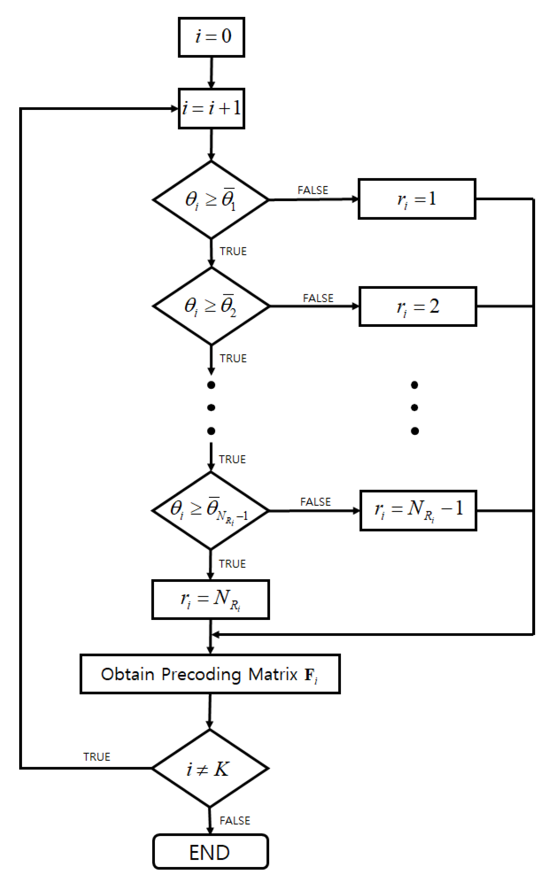
4.2. Adaptive MGBD Precoder

The adaptive MGBD precoder adjusts the number of data streams of each UE according to received SNR for each UE. The algorithm for the adaptive MGBD precoder is represented in Figure 3. BS can know the received SNR for each UE and θ i is the received SNR of the i-th UE which BS knows. Also, it is assumed that each UE has N R i receive antennas and BS has threshold table for θ ¯ 1 , θ ¯ 2 , , θ ¯ N R i 1 . The threshold table is an indicator for the number of data streams which provides maximum throughput. First, the adaptive MGBD precoder compares the received SNR θ 1 of the first UE with threshold SNR θ ¯ 1 which previously is obtained through training data. Then, the adaptive MGBD precoder continuously compares θ 1 to other thresholds and selects the suitable r 1 . Therefore, BS transmits r 1 data streams which maximize throughput at θ 1 . The adaptive MGBD precoder repeats these steps from the second UE to the K-th UE. Afterward, the adaptive MGBD precoder calculates Equation (28) by using r 1 , r 2 , , r K in order to obtain precoding matrix. Through these steps, the proposed scheme achieves maximum throughput within the limited SNR of each UE.
The initial threshold values can be obtained through mathematical analysis or the Monte Carlo method. However, the former method is very difficult to estimate threshold values for all channel environments and can lead to a large error due to the approximation processes for the number of data streams [22]. Thus, in this paper, the SNR points of switching the number of data streams are obtained by comparing the results which are gained through previous simulation. The previous simulation is performed by training data which is only used to obtain initial threshold values. Then, the BS stores these SNR points in the form of a threshold table.

5. Simulation Results
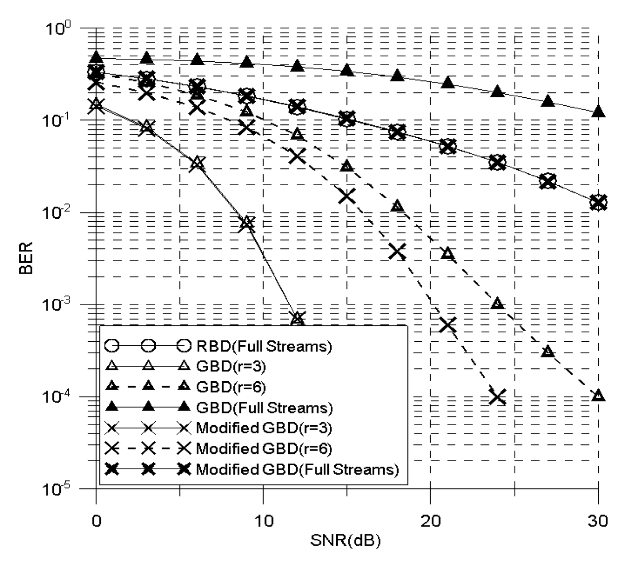
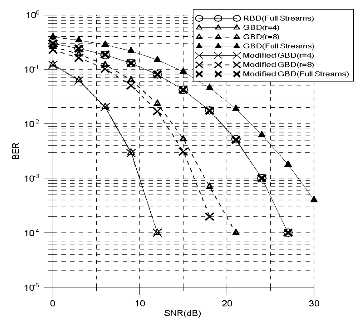
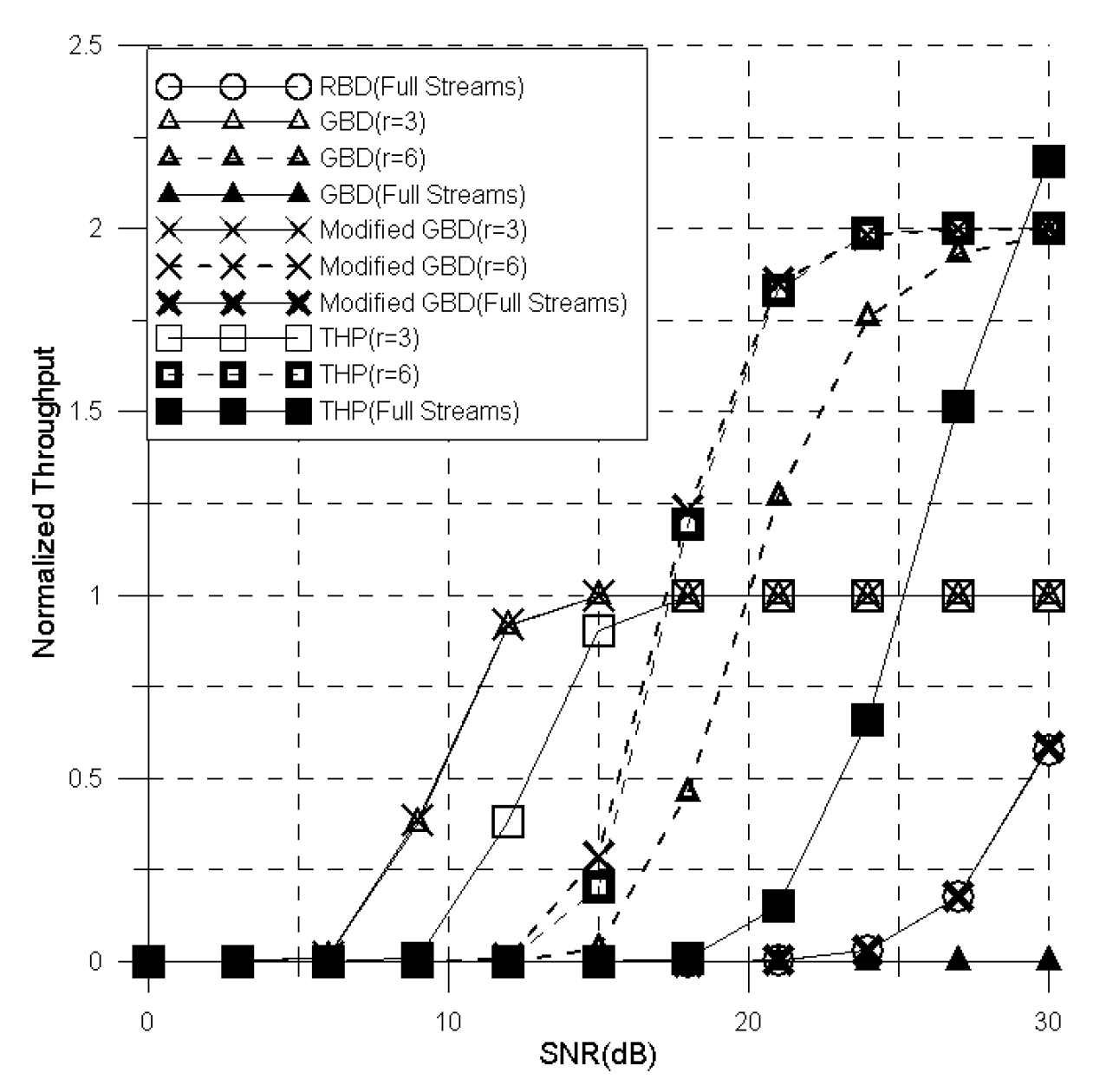
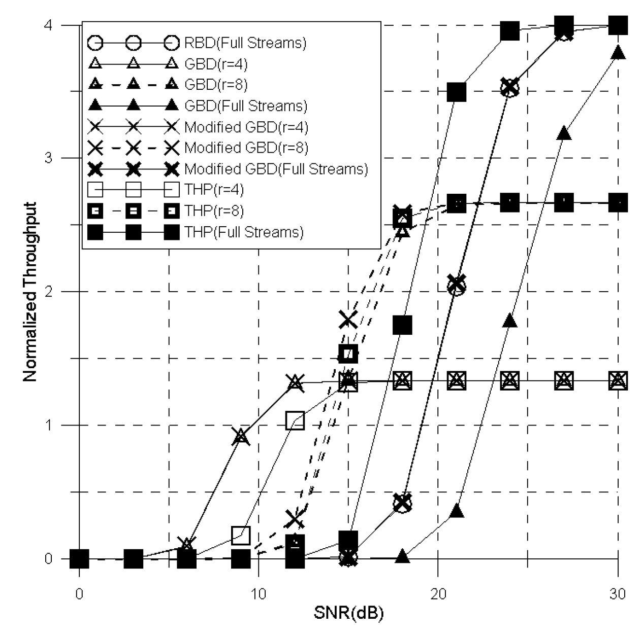
This section analyzes BER and throughput performaces for proposed scheme. In the first subsection, the MGBD precoder is compared to the RBD and the GBD precoder. In second subsection, the throughput performances for the adaptive MGBD and GBD precoder are represented according to SNR. The simulation parameters are shown in Table 1. All simulations are performed by MATLAB, and the BER performances are measured by Monte Carlo method. Then, the simulation results are provided by averaging a large number of results for a given SNR to obtain reliable BER values. Additionally, this simulation considers a Rayleigh flat fading channel environment for which the channel components with zero mean unit variance are i.i.d. Also, it is assumed that the number of data streams for all UEs is the same and the CSI is estimated perfectly at BS and all UEs.

5.1. MGBD Precoder

The MGBD precoder is compared to the conventional precoders in terms of BER and throughput performances.
The Figure 4 and Figure 5 show the BER performance for the MGBD precoder, RBD precoder and GBD precoder according to SNR. Also, Figure 4 shows the BER performance when each of the 3 UEs has 3 receive antennas and BS has 9 transmit antennas and Figure 5 is BER performance when each of the 4 UEs has 3 receive antennas and BS has 16 transmit antennas. In Figure 4 and Figure 5, the BER performance for the proposed scheme increases compared with the GBD precoder at all SNRs and all cases except for minimum data streams ( r = 3 or r = 4 ). Compared to GBD, the performance gain of the MGBD precoder is about 3 dB ( r = 6 ) to 15 dB (full streams) when each of the 3 UEs has 3 receive antennas and BS has 9 transmit antennas according to Figure 4. In Figure 5, the MGBD precoder obtains about 2 dB ( r = 8 ) to 5 dB (full streams) gain in comparison with GBD precoder when each of the 4 UEs has 3 receive antennas and BS has 16 transmit antennas. This advantage is obtained by optimizing with a modified MMSE criterion like Equation (12). If the BS transmits minimum data stream, the extra BER gain that the modified MMSE criterion provides is negligible in comparison with diversity gain. Thus, the BER performance for the MGBD precoder is equal to the BER performance for the GBD precoder when BS transmits minimum data streams. The degrees of freedom for MGBD and GBD precoder increases as the data streams decrease. Therefore, the BER performance is maximized when BS transmits 1 data stream to each UE and is minimized when BS transmits full data streams by consuming all ranks for the channel. In this case, the MGBD precoder does not obtain extra diversity gain; thus, the BER performance for the proposed scheme is the same as the BER performance for the RBD precoder.
The gap for BER performance between MGBD and GBD precoder in Figure 5 decreases more than the gap for BER performance in Figure 4. Because extra BER gain is obtained by increasing the number of transmit antennas relative to the number of receive antennas, the gap for BER performance decreases in both precoders.
Figure 6 and Figure 7 represent normalized throughput performance for the modified GBD precoder, RBD precoder and GBD precoder according to SNR. Also, the throughput performances for the proposed scheme are compared with Tomlinson-Harashima precoding (THP), which is well known as a suboptimal precoder in the MU-MIMO system [23] to show the superiority of the proposed scheme. Both figures show that peak value for normalized throughput is enhanced as the number of data streams increases. However, the required SNR where a peak value for normalized throughput is achieved rises as the number of data streams increases.
First, in the both cases, THP reaches maximum throughput rapidly when BS transmits data with full streams. However, the throughput performance for the MGBD outperforms the THP when BS transmits data with lower than the maximum streams ( r = 3 , r = 6 in Figure 6 and r = 4 , r = 8 in Figure 7). Also, the GBD obtains more gain than the THP in minimum streams, and the gap between these precoders decreases as the number of streams reduces. These results are effected by the MGBD and GBD obtaining more diversity gain than the THP since the partial nulling is used. Additionally, the gap of throughput performance between the MGBD and THP is large when the SNR is low since the proposed scheme obtains additional SNR gain by mitigating noise components.
The MGBD precoder provides improved throughput performance compared to the GBD precoder at all SNRs and all cases, except for minimum data streams ( r = 3 or r = 4 ). In more detail, the MGBD precoder provides about 3 dB ( r = 6 ) gain in comparison with GBD precoder when each of the 3 UE has 3 receive antennas and BS has 9 transmit antennas according to Figure 6. Compared to GBD, the performance gain of the MGBD precoder is about 1 dB ( r = 8 ) to 4 dB (full streams) when each of the 4 UEs has 3 receive antennas and BS has 16 transmit antennas in Figure 7. The improvement for throughput performance can be predicted through Figure 4 and Figure 5. In short, the throughput performance improves when the BER performance improves. Like the BER performance, the throughput performance for proposed scheme is the same as that of the RBD precoder when BS transmits the full data stream and is the same as the GBD precoder when BS transmits the minimum data stream. Because the BER performance is not enough to obtain the reasonable throughput performance, if BS transmits a full stream in Figure 6, this presents poor performance. In other words, although the RBD precoder transmits a signal with maximum data streams, the peak value of the throughput performance for RBD only achieved 33% of the peak value for the MGBD precoder ( r = 6 ) and 60% of the peak value for the MGBD precoder ( r = 3 ) when SNR is less than 30 dB.

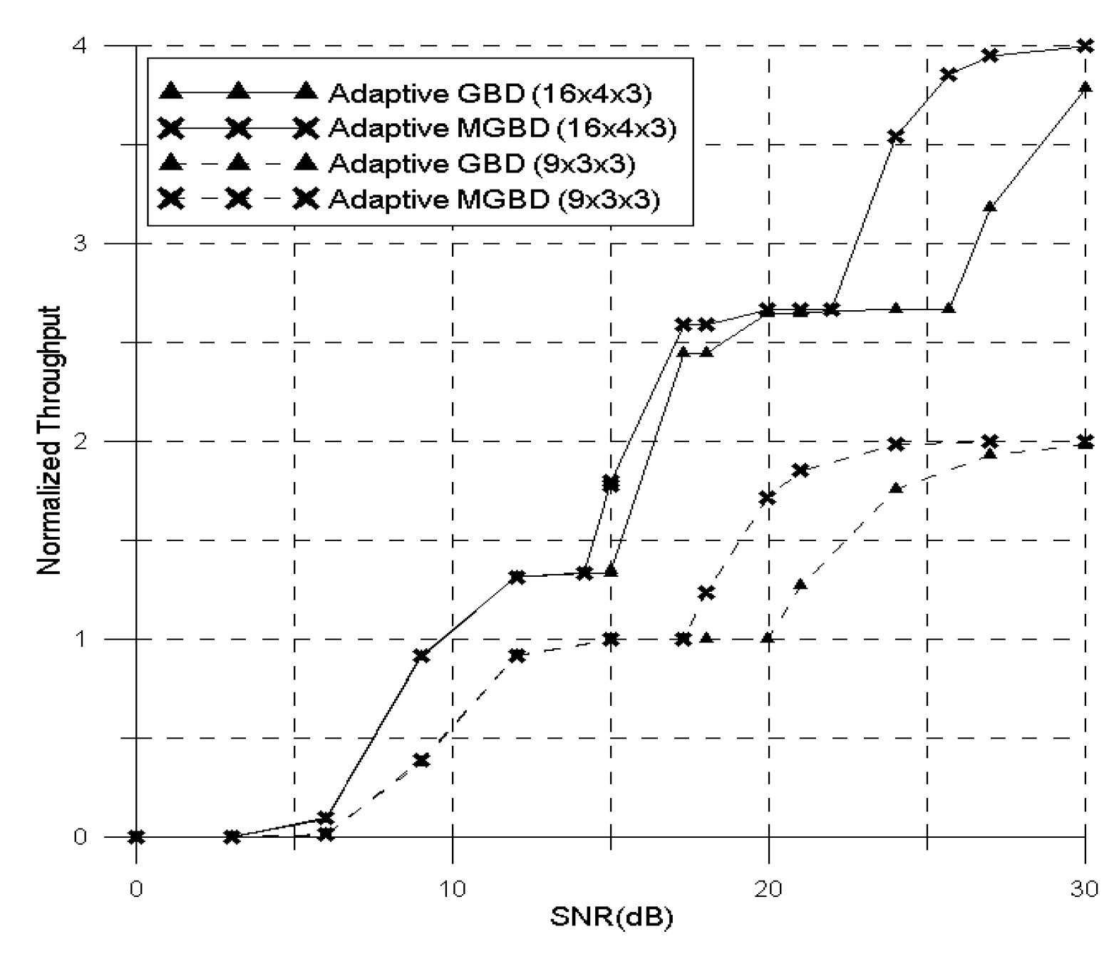
5.2. Adaptive MGBD Precoder

In this subsection, throughput performance for the adaptive MGBD precoder is compared with throughput performance for the adaptive GBD precoder. The algorithm for the adaptive GBD precoder is the same as Figure 3 and uses Equation (17) in order to obtain the precoding matrix. The dotted line in Figure 8 is throughput performance when each of the 3 UEs has 3 receive antennas and BS has 9 transmit antennas and the solid line in Figure 8 is throughput performace when each of the 4 UEs has 3 receive antennas and BS has 16 transmit antennas. Because the BER performance for the MGBD precoder is better than that of the GBD precoder, the required SNR for which the adaptive MGBD precoder changes the number of data streams is lower than adaptive GBD precoder. This advantage implies that the required SNR for the MGBD precoder is lower than the GBD precoder in order to achieve the desired throughput. Also, the gap for throughput performance between adaptive MGBD and adaptive GBD precoder increases as SNR grows. In other words, the gain of throughput performance for the MGBD precoder increasingly grows as the number of data streams increases compared to GBD. Although the RBD precoder provides the same peak value as MGBD, the RBD precoder does not obtain any throughput performance in low SNR. For these reasons, unlike other schemes, the MGBD precoder maximizes throughput at any SNRs.

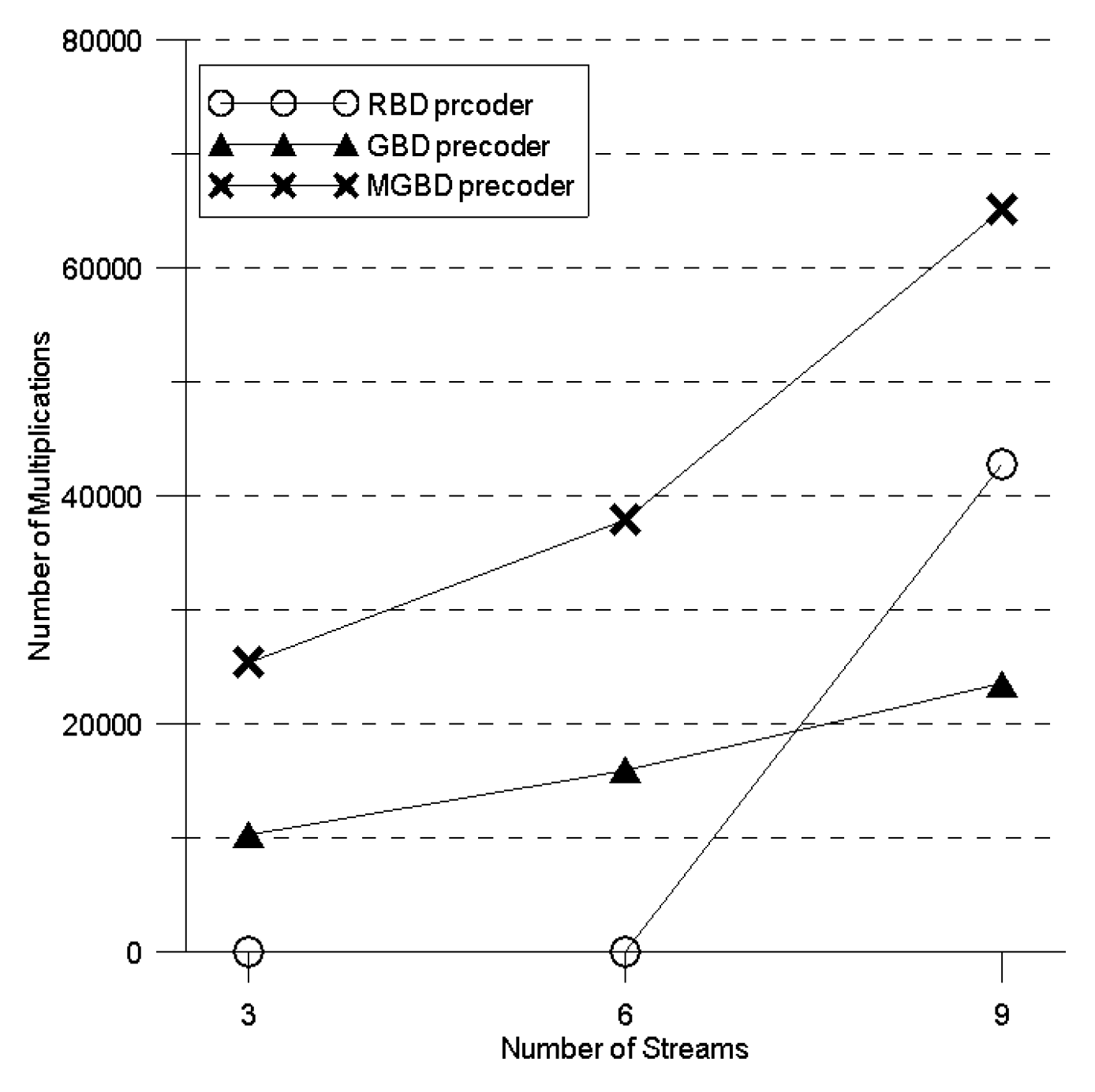
5.3. Computational Complexity Analysis

This subsection provides the comparison of computational complexity for RBD precoder, GBD precoder and MGBD precoder.
It is assumed that one complex multiplication requires four multiplications. Also, process to obtain the precoding matrix for RBD and MGBD precoders is similar and most of computational complexity is caused by SVD operation. Therefore, this discussion only calculates computational complexity for SVD in the cases of RBD and MGBD precoders. On the other hand, most of the computational complexity for GBD is caused not only by SVD, but also Equation (17). Thus, the process of calculating complexity for GBD considers SVD operation and Equation (17). Table 2 shows computational complexity for two methods of SVD operation when dimensions of a complex matrix are M × N [24].
The MGBD precoder, RBD precoder and GBD precoder require respectively three, two and one SVD operation. The computational complexity for all precoders is represented in Table 3, Table 4 and Table 5. Figure 9 shows a comparison for computational complexity when each of the 3 UEs has 3 receive antennas and BS has 9 transmit antennas. In this case, the number of multiplications for the MGBD precoder is lower than the RBD precoder, except for 3 streams. In more detail, the computational complexity for MGBD precoder reduces by about 40% ( r = 3 ) and 10% ( r = 6 ) compared to RBD, when BS transmits a data signal with lower than full streams. In contrast, the number of multiplications for MGBD increases by 50% compared to RBD, when BS transmits a data signal with full streams. The complexity can be reduced by setting G i to the unit matrix when BS transmits full streams. The MGBD precoder obtains a precoding matrix F by the same method as the RBD precoder when G i is changed to the unit matrix. On the other hand, the computational complexity for MGBD is always higher than the computational complexity for GBD. Since the GBD precoder is not optimized with MMSE criterion, the performance of the GBD precoder is degraded and computational complexity for the GBD precoder is low.
Since MGBD and GBD eliminate remaining IUI by utilizing postcoding, additional multiplications are required. The number of additional multiplications for both precoders is the same as the first row in Table 5. Although the computational complexity for MGBD postcoding is independent of the number of data streams, in common with the RBD precoder, extra SVD operation is not needed by setting G i to the unit matrix when UE receives full streams.

6. Conclusions

In this paper, an MGBD precoder is proposed by optimization with modified MMSE criterion and simultaneously performing partial nulling. Because the noise component is additionally considered, the simulation results show that the proposed scheme provides improved BER and throughput performances compared to GBD. The proposed scheme obtains diversity gain by reducing the number of data streams unlike RBD. These advantages provide the possibility that the MGBD precoder obtains maximum throughput in all SNRs by adaptively changing the number of data streams according to channel state. In exchange for this performance improvement, the proposed scheme has higher complexity than RBD and GBD. Although the number of multiplications for the MGBD precoder is higher than that of the RBD precoder when BS transmits full streams, the MGBD precoder can reduce system complexity by setting the postcoding matrix to a unit matrix. Also, an adaptive MGBD precoder for which throughput performance is maximized at all SNRs is proposed. The conventional RBD requires high SNR in order to obtain appropriate throughput and the throughput performance for conventional GBD is lower than for the proposed scheme. Additionally, the gap for throughput performance between adaptive MGBD and the adaptive GBD precoder increases as the number of data streams grows. Thus, the proposed scheme reduces the required SNR in order to obtain the desired throughput. These advantages are valuable in wireless communication systems, because high throughput performance is achieved at unfavorable channel conditions.

Author Contributions

Conceptualization, W.-S.L.; methodology, W.-S.L. and J.-H.R.; software, W.-S.L.; validation, W.-S.L., J.-H.R., Y.-H.Y., D.H. and H.-K.S.; formal analysis, W.-S.L.; investigation, J.-H.R. and Y.-H.Y.; writing–original draft preparation, W.-S.L.; writing–review and editing, W.-S.L.; supervision, Y.-H.Y., D.H. and H.-K.S.; project administration, D.H. and H.-K.S. All authors have read and agreed to the published version of the manuscript.

Funding

This work was supported by Institute for Information & communications Technology Promotion(IITP) grant funded by the Korea government(MSIT) (No.2017-0-00217, Development of Immersive Signage Based on Variable Transparency and Multiple Layers) and was supported by the MSIT(Ministry of Science and ICT), Korea, under the ITRC(Information Technology Research Center) support program(IITP-2019-2018-0-01423) supervised by the IITP(Institute for Information & communications Technology Promotion). Corresponding author: Hyoung-Kyu Song.

Conflicts of Interest

The authors declare no conflict of interest.

Appendix A. Derivation of FMU

This section explains proof that F MU is optimized with modified MMSE criterion. The F MU is designed that diversity gain is preserved and MSE is minimized. The postcoding matrix removes the remaining IUI and F MU is obtained as Equation (23). The Equation (23) can be rewritten as follows,
F MU = arg min F MU E i = 1 K t r T ˜ i F MU , i F MU , i H T ˜ i H + t r G W W H G H γ 2 = arg min F MU i = 1 K t r T ˜ i H T ˜ i F MU , i F MU , i H + E t r G H G W W H γ 2 = arg min F MU i = 1 K t r T ˜ i H T ˜ i F MU , i F MU , i H + r σ W 2 γ 2 .
The power for trasmitted signal vector is constrained to P T as follows,
E X ¯ 2 = E i = 1 K γ F MU , i F SU , i X i 2 = E i = 1 K t r γ 2 F MU , i F SU , i X i X i H F SU , i H F MU , i H = γ 2 t r i = 1 K F MU , i F SU , i E X i X i H F SU , i H F MU , i H = γ 2 t r i = 1 K F MU , i F SU , i F SU , i H F MU , i H = P T .
F SU , i is designed as unitary matrix. Therefore, the scaling factor γ satisfies as follows,
γ 2 = P T t r i = 1 K F MU , i F MU , i H .
By substituting Equation (A3) into Equation (A1), Equation (A1) is given by,
F MU = arg min F MU i = 1 K t r T ˜ i H T ˜ i F MU , i F MU , i H + r σ W 2 P T t r i = 1 K F MU , i F MU , i H = arg min F MU i = 1 K t r T ˜ i H T ˜ i F MU , i F MU , i H + r σ W 2 P T F MU , i F MU , i H = arg min F MU i = 1 K t r T ˜ i H T ˜ i + r σ W 2 P T I T F MU , i F MU , i H = arg min F MU i = 1 K t r F MU , i H T ˜ i H T ˜ i + r σ W 2 P T I T F MU , i .
The SVD for T ˜ i is T ˜ i = U i Σ i V i H and eigen decomposition for T ˜ i H T ˜ i is T ˜ i H T ˜ i = V i Σ i T Σ i V i H . Then,
F MU = arg min F MU ( i = 1 K t r ( F MU , i H V i ( Σ i T Σ i + r σ W 2 P T I T ) V i H F MU , i ) ) .
The solution of Equation (A5) is obtained like [20] (Appendix). Consequently, F MU , i is given by,
F MU , i = V i ( Σ i T Σ i + r σ W 2 P T I N T ) 1 2 .

References

  1. Dahlman, E.; Parkvall, S.; Skold, J. 4G, LTE-Advanced Pro and the Road to 5G; Academic Press: Cambridge, MA, USA, 2016. [Google Scholar]
  2. Heath, R.W.; Airy, M.; Paulraj, A.J. Multiuser diversity for MIMO wireless systems with linear receivers. In Proceedings of the Conference Record of Thirty-Fifth Asilomar Conference on Signals, Systems and Computers (Cat.No.01CH37256), Pacific Grove, CA, USA, 4–7 November 2001; pp. 1194–1199. [Google Scholar]
  3. Pan, Z.G.; Wong, K.K.; Ng, T.S. MIMO antenna system for multi-user multi-stream orthogonal space division multiplexing. In Proceedings of the IEEE International Conference on Communications, ICC ’03, Anchorage, AK, USA, 11–15 May 2003; pp. 3220–3224. [Google Scholar]
  4. Vishwanath, S.; Jindal, N.; Goldsmith, A. On the capacity of multiple input multiple output broadcast channels. In Proceedings of the IEEE International Conference on Communications, ICC 2002 (Cat. No.02CH37333), New York, NY, USA, 28 April–2 May 2002; pp. 1444–1450. [Google Scholar]
  5. Spencer, Q.H.; Peel, C.B.; Swindlehurst, A.L.; Haardt, M. An introduction to the multi-user MIMO downlink. IEEE Commun. Mag. 2004, 42, 60–67. [Google Scholar] [CrossRef]
  6. Sampath, H.; Talwar, S.; Tellado, J.; Erceg, V.; Paulraj, A. A fourth-generation MIMO-OFDM broadband wireless system: Design, performance, and field trial results. IEEE Commun. Mag. 2002, 40, 143–149. [Google Scholar] [CrossRef]
  7. Castillo-Soria, F.R.; Sánchez-García, J.; Maciel-Barboza, M.; Flores-Troncoso, J. Multiuser MIMO downlink transmission using block diagonalization and generalized spatial modulation techniques. AEU-Int. J. Electron. Commun. 2016, 70, 1228–1234. [Google Scholar] [CrossRef]
  8. Vishwanath, S.; Jindal, N.; Goldsmith, A. Duality, achievable rates, and sum-rate capacity of Gaussian MIMO broadcast channels. IEEE Trans. Inf. Theory 2003, 49, 2658–2668. [Google Scholar] [CrossRef] [Green Version]
  9. Viswanath, P.; Tse, D.N.C. Sum capacity of the vector Gaussian broadcast channel and uplink-downlink duality. IEEE Trans. Inf. Theory 2003, 49, 1912–1921. [Google Scholar] [CrossRef] [Green Version]
  10. Swales, S.C.; Beach, M.A.; Edwards, D.J.; McGeehan, J.P. The performance enhancement of multibeam adaptive base-station antennas for cellular land mobile radio systems. IEEE Trans. Veh. Technol. 1990, 39, 56–67. [Google Scholar] [CrossRef]
  11. Costa, M. Writing on dirty paper (corresp.). IEEE Trans. Inf. Theory 1983, 10, 439–441. [Google Scholar] [CrossRef]
  12. Ginis, G.; Cioffi, J.M. A multi-user precoding scheme achieving crosstalk cancellation with application to DSL systems. In Proceedings of the Conference Record of the Thirty-Fourth Asilomar Conference on Signals, Systems and Computers (Cat. No.00CH37154), Pacific Grove, CA, USA, 29 October–1 November 2000; pp. 1627–1631. [Google Scholar]
  13. Windpassinger, C.; Fischer, R.F.; Vencel, T.; Huber, J.B. Precoding in multiantenna and multiuser communications. IEEE Trans. Wirel. Commun. 2004, 3, 1305–1316. [Google Scholar] [CrossRef]
  14. Spencer, Q.H.; Swindlehurst, A.L.; Haardt, M. Zero-forcing methods for downlink spatial multiplexing in multiuser MIMO channels. IEEE Trans. Signal Process. 2004, 52, 461–471. [Google Scholar] [CrossRef]
  15. Khai, L.D. Low-Complexity Block Diagonalization Precoder Hardware Implementation for MU-MIMO 4 × 4. J. Inf. Commun. Converg. Eng. 2019, 17, 1–7. [Google Scholar]
  16. Stankovic, V.; Haardt, M. Generalized design of multi-user MIMO precoding matrices. IEEE Trans. Wirel. Commun. 2008, 7, 953–961. [Google Scholar] [CrossRef]
  17. Sada, T.; Webber, J.; Nishimura, T.; Ohgane, T.; Ogawa, Y. A generalized approach to block diagonalization for multiuser MIMO downlink. In Proceedings of the 1st Annual IEEE International Symposium on Personal, Indoor and Mobile Radio Communications, Instanbul, Turkey, 26–30 September 2010; pp. 504–509. [Google Scholar]
  18. Flores, A.R.; de Lamare, R.C.; Clerckx, B. Linear Precoding and Stream Combining for Rate Splitting in Multiuser MIMO Systems. IEEE Commun. Lett. 2020, 24, 890–894. [Google Scholar] [CrossRef]
  19. Ha, J.G.; Ro, J.H.; Song, H.K. Throughput Enhancement in Downlink MU-MIMO Using Multiple Dimensions. Electronics 2019, 8, 758. [Google Scholar] [CrossRef] [Green Version]
  20. Scaglione, A.; Stoica, P.; Barbarossa, S.; Giannakis, G.B.; Sampath, H. Optimal designs for space-time linear precoders and decoders. IEEE Trans. Signal Process. 2002, 50, 1051–1064. [Google Scholar] [CrossRef]
  21. Nishimoto, H.; Kato, S.; Ogawa, Y.; Ohgane, T.; Nishimura, T. Imperfect block diagonalization for multiuser MIMO downlink. In Proceedings of the 2008 IEEE 19th International Symposium on Personal, Indoor and Mobile Radio Communications, Cannes, France, 15–18 September 2008. [Google Scholar]
  22. Chae, C.B.; Forenza, A.; Heath, R.W.; McKay, M.R. Adaptive MIMO transmission techniques for broadband wireless communication systems [Topics in Wireless Communications]. IEEE Commun. Mag. 2010, 48, 112–118. [Google Scholar] [CrossRef]
  23. Chen, X.; Huang, M.; Zhao, M.; Zhou, S.; Wang, J. Analysis and Design of Tomlinson-Harashima Precoding for Multiuser MIMO Systems. In MIMO Systems, Theory and Applications; Bizaki, H.K., Ed.; IntechOpen: London, UK, 2011; pp. 237–264. [Google Scholar]
  24. Zu, K.; De Lamare, R.C. Low-complexity lattice reduction-aided regularized block diagonalization for MU-MIMO systems. IEEE Commun. Lett. 2012, 16, 925–928. [Google Scholar] [CrossRef]
Figure 1. The multi user multiple-input multiple-output (MIMO) downlink system model.
Applsci 10 04547 g001
Figure 2. The equivalent single user (SU) model of the i-th user equipment (UE).
Applsci 10 04547 g002
Figure 3. The algorithm of the adaptive modified generalized block diagonalization (MGBD) precoder.
Applsci 10 04547 g003
Figure 4. The bit error rate (BER) comparison when each of the 3 UEs has 3 receive antennas and the base station (BS) has 9 transmit antennas.
Applsci 10 04547 g004
Figure 5. The BER comparison when each of the 4 UEs has 3 receive antennas and the BS has 16 transmit antennas.
Applsci 10 04547 g005
Figure 6. The throughput comparison when each of the 3 UEs has 3 receive antennas and the BS has 9 transmit antennas.
Applsci 10 04547 g006
Figure 7. The throughput comparison when each of the 4 UEs has 3 receive antennas and the BS has 16 transmit antennas.
Applsci 10 04547 g007
Figure 8. Comparison of the throughput performances for adaptive MGBD and adaptive GBD.
Applsci 10 04547 g008
Figure 9. The comparison for computational complexity when each of 3 UEs has 3 receive antennas and BS has 9 transmit antennas.
Applsci 10 04547 g009
Table 1. The simulation parameters.
ParametersValues
Number of simulation iterations100,000
Data size512
Number of receive antennas3
Number of transmit antennas16, 9
Number of UEs4, 3
ChannelComplex Rayleigh flat fading
Modulation order16-quadrature amplitude
modulation (QAM)
DecoderZero forcing (ZF)
Table 2. Computational complexity for SVD operation of an M × N complex matrix.
OperationNumber of Multiplications
SVD that only obtains Σ , V 16 N M 2 + 2 M 3
Full SVD that obtains U , Σ , V 4 4 N 2 M + 8 N M 2 + 9 M 3
Table 3. Computational complexity for a regularized block diagonalization (RBD) precoder.
OperationNumber of Multiplications
H ˜ i = U ˜ i Σ ˜ i V ˜ i ( 1 ) V ˜ i ( 0 ) H 16 K K 1 2 N T N R i 2 + 2 K 1 3 N R i 3
(Equation (13))
H i F MU , i RBD = U ¯ i RBD Σ ¯ i RBD V ¯ i RBD ( 1 ) V ¯ i RBD ( 0 ) H 16 K N T N R i 2 + 2 N R i 3
(Equation (14))
Total Complexity 16 K K 2 2 K + 2 N T N R i 2 + 2 K 3 3 K 2 + 3 K N R i 3
Table 4. Computational complexity for a generalized block diagonalization (GBD) precoder.
OperationNumber of Multiplications
H i = U i Σ i V i H 16 K N T N R i 2 + 2 N R i 3
(Equation (16))
P i = I D ˜ i D ˜ i H D ˜ i 1 D ˜ i H D i K 4 K N T 2 r i + 8 K 1 2 N T r i 2 + K 1 3 r i 3 K 1 2 r i 2 + 1 2 K 1 r i
(Equation (17))
Total Complexity K 4 K N T 2 r i + 16 N T N R i 2 + 8 K 1 2 N T r i 2 + 32 N R i 3 + K 1 3 r i 3 K 1 2 r i 2 + 1 2 K 1 r i
Table 5. Computational complexity for MGBD precoder.
OperationNumber of Multiplications
H i = U i Σ i V i H 4 K 4 N T 2 N R i + 8 N T N R i 2 + 9 N R i 3
(Equation (21))
T ˜ i = U i Σ i V i H 16 K K 1 2 N T r i 2 + 2 K 1 3 r i 3
(Equation (26))
H i F MU , i = U ¯ i Σ ¯ i V ¯ i ( 1 ) V ¯ i ( 0 ) H 16 K N T r i 2 + 2 r i 3
(Equation (27))
Total Complexity 16 K N T 2 N R i + 2 N T N R i 2 + K 2 2 K + 2 N T r i 2 + 9 4 N R i 3 + 2 K 3 3 K 2 + 3 K r i 3

