Abstract
Most of currently rehabilitation robots cannot achieve the adduction/abduction (A/A) training of the hip joint and lack the consideration of the patient handling. This paper presents a four degrees of freedom (DOF) spatial workspace lower limb rehabilitation robot, and it could provide flexion/extension (F/E) training to three lower limb joints and A/A training to the hip joint. The training method is conducting the patient’s foot to complete the rehabilitation movement, and the patient could directly take training on the wheelchair and avoid frequent patient handling between the wheelchair and the rehabilitation device. Because patients own different joint range of motions (ROM), an analysis method for obtaining human joint motions is proposed to guarantee the patient’s joint safety in this training method. The analysis method is based on a five-bar linkage kinematic model, which includes the human lower limb. The human-robot hybrid kinematic model is analyzed according to the Denavit-Hartenberg (D-H) method, and a variable human-robot workspace based on the user is proposed. Two kinds of trajectory planning methods are introduced. The trajectory planning method and the human joint analysis method are validated through the trajectory tracking experiment of the prototype.
1. Introduction
As a common disease in the elderly population, stroke has a high probability of causing physical-motor disability [1,2]. The disability seriously affects the lives and families of patients. There are several million newer stroke patients every year in the world [3,4]. It means that the traditional manual rehabilitation by therapists cannot meet the great demand for rehabilitations. The rehabilitation robot is an efficient human-robot interaction system, which could be applied in stroke, sport injuries and surgery rehabilitations. The effect of rehabilitation robots has been verified and recognized through the clinical trial in last decades [5,6,7].
The lower rehabilitation robot has been rapidly developed in recent years, and it could be divided into exoskeletons, moving platforms and parallel platforms [8]. Exoskeletons mainly refer to the wearable human-like mechanical legs. Rehabilitation exoskeletons are generally equipped with a treadmill and a weight reducing device, and exoskeletons could assist the user to complete the gait training on the treadmill [9,10,11,12,13,14]. A lower limb gait training rehabilitation robot named AIRGAIT has been developed by Shibaura Institute of Technology, and the exoskeleton of AIRGAIT mainly consists of a robotic orthosis, springs and parallel linkages [15]. Currently, the available moving platform robots have many types of mechanical structures; the training methods of them are carrying the limb to achieve the movement through terminal pedals or platforms [16,17,18,19,20,21]. A 5-DOF (degrees of freedom) hip-joint rehabilitation robot allows for full movements of the hip joint, and the user lying on the robot could be conducted to complete the training by the platform [22]. The working method of parallel platforms is same as moving platforms, and parallel platforms are generally applied in ankle joint rehabilitations because the workspace is limited by parallel structures [23,24,25,26,27,28]. A 9-DOF hybrid parallel ankle rehabilitation robot has been investigated by Rakhodaei et al., which consists of nine linear actuators and two moving platforms [29]. A comparison summary of typical lower rehabilitation robots is shown in Table 1.

Table 1.
Comparison summary of typical lower rehabilitation robots. Hip (H), Knee (K), Ankle (A), Leg (L), Bed (B), Wheelchair (W) and Device (D).
However, although various types of rehabilitation robots have been developed, little attention is paid to the adduction/abduction (A/A) training of the hip joint, and the problem of the patient handling before training. Currently, available rehabilitation robots could seldom achieve the hip A/A training. Besides, most of rehabilitation robots are inconvenient to the patient handling. It generally takes at least two medical staffs to help the patient (no standing ability) move in the rehabilitation device.
This paper proposes a 4-DOF spatial workspace rehabilitation robot, which could perform the A/A training in the hip joint and the flexion/extension (F/E) training in three joints of the lower limb. Because of the reliably mechanical structure and the newer working method, patients could directly do their rehabilitation training on wheelchairs without patient handling. On account of the spatial workspace, this robot could achieve the circumduction training of the hip joint. Circumduction training is a thigh conical motion combined with the F/E and the A/A, and several studies have proved that the circumduction training is quite helpful to the hip rehabilitation after the hip surgery [30,31]. As the working method of this robot is conducting the patient’s foot to complete the training movement, the patient’s joint range of motions (ROM) must be guaranteed. The solution is proposing an analysis method for obtaining human joint motions. This robot could plan the trajectory depending on the of patient’s joint ROM. Moreover, the research has demonstrated that there is a window of enhanced neuroplasticity early after stroke [32]. Compared to other rehabilitation robots, this robot could participate in rehabilitation therapy earlier. That is, the patient in the flaccid paralysis period could use this device under the guidance of the doctor.
In this paper, the mechanical structure of this robot is shown in the Section 1. The human-robot hybrid kinematic model, the kinematic analysis and the human joint analysis are introduced in Section 2. Section 3 shows the human-robot workspace and two methods of the trajectory planning. Finally, the trajectory tracking experiment and the result analysis are shown in the Section 4.
2. Mechanism Design
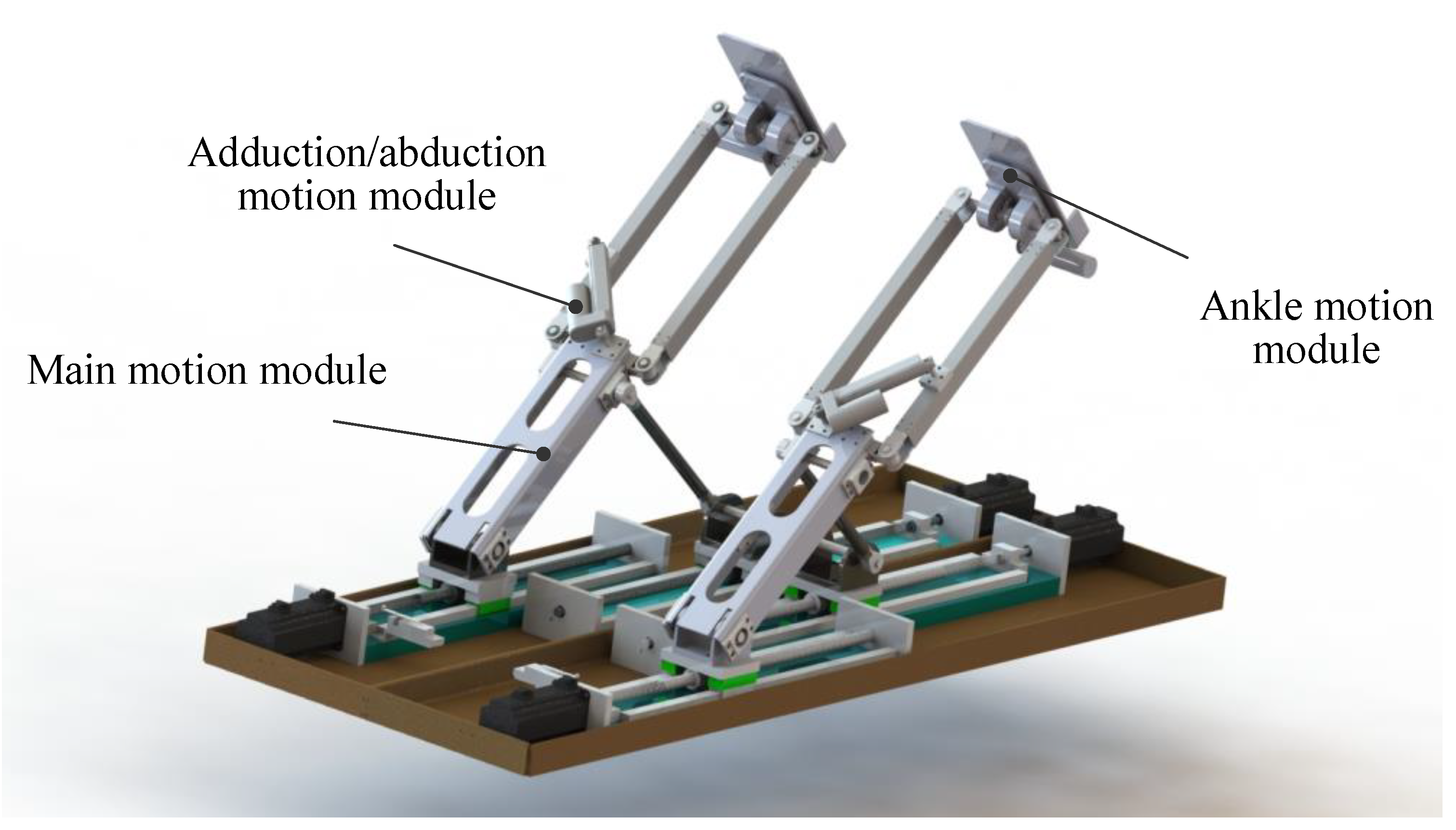
This robot consists of two symmetric leg training parts, as shown in Figure 1, and each part includes the main motion module, the adduction/abduction motion module and the ankle motion module. Each leg training part could provide training for left/right legs, and the left/right leg training mode could be switched by changing the assembling position of the linear actuator. This robot could provide passive training, teaching training and resistance training. One of leg training parts is introduced in following chapters.
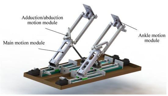
Figure 1.
4-DOF (degrees of freedom) spatial workspace lower limb rehabilitation robot.
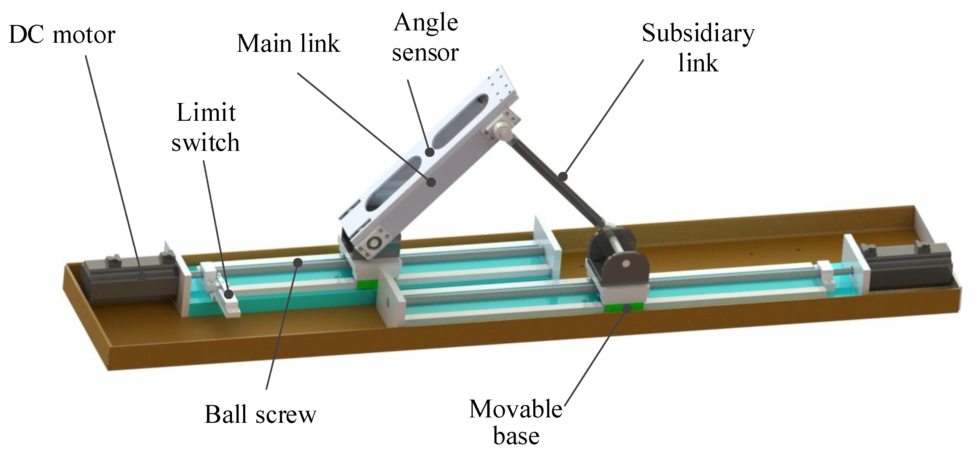
As shown in Figure 2, the main motion module is a 2-DOF parallel mechanism working in the sagittal plane. The 2-DOF parallel mechanism has a reliably bearing capability, and this design could reduce the robot width size. The drive line consists of a DC motor, a ball screw and a movable base; it could convert angle displacements of the motors into linear displacements of bases. Two opposite drive lines are fixed on the underframe. The cooperation of double base motions could provide linear and angled sagittal motions to the upper mechanism. The range of the angle displacement is from 25° to 80°; the maximum linear displacement is 500 mm. An angle sensor is assembled in the main link, and a limit switch is fixed on the far end of the main ball screw. The measuring range of the angle sensor is ±180°, and the precision is ±0.2°. The sensor and the limit switch are used for the safety detection and the amplifier homing.
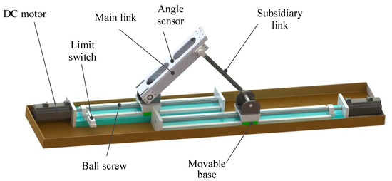
Figure 2.
Main motion module.
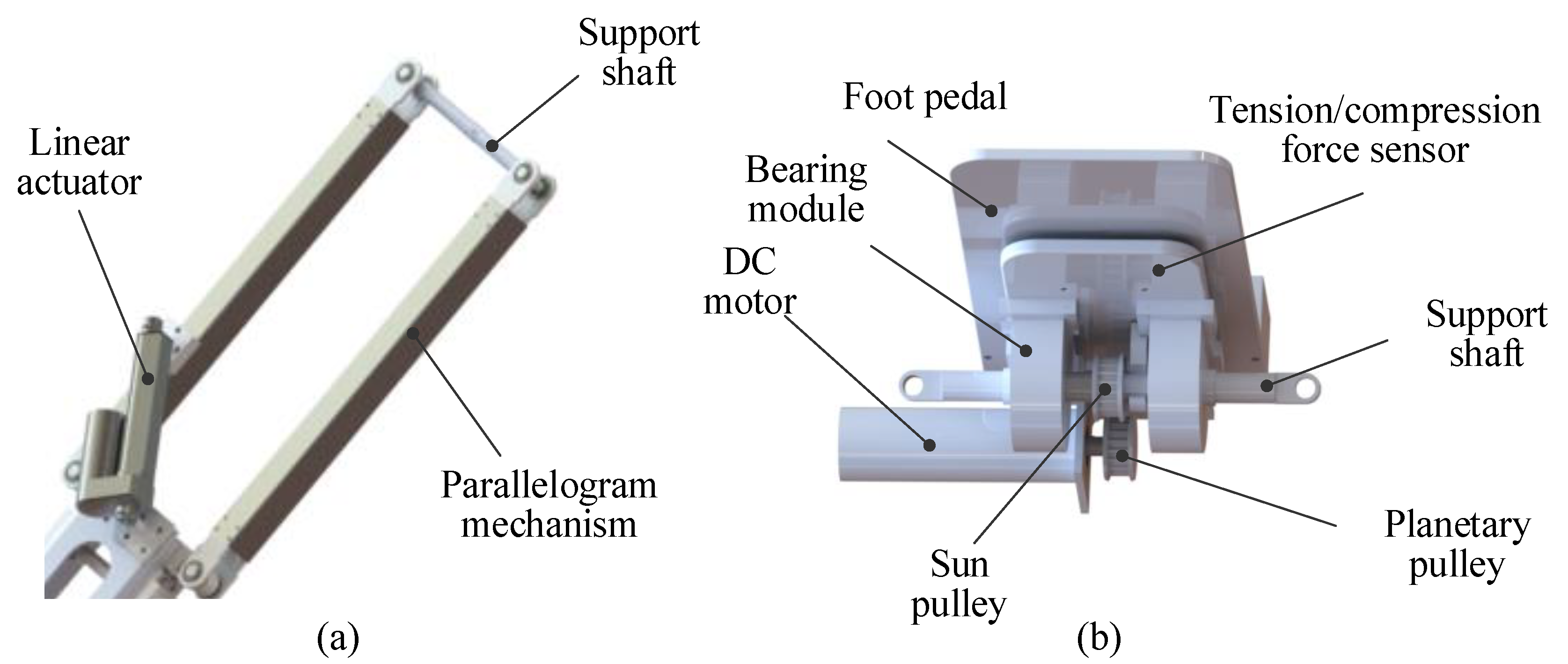
The adduction/abduction motion module is a parallelogram mechanism, as shown in Figure 3a, which is fixed on the main motion module. The A/A movement of the hip is conducted by the motion of the parallelogram mechanism; the parallelogram mechanism is driven by a linear actuator assembled on the main motion module (Figure 6b). The linear actuator is in the minimum length while the parallelogram mechanism is collinear to the main motion module; the maximum angle between the parallelogram mechanism and the main motion module is 40° while the linear actuator is in the maximum length.
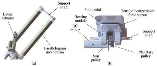
Figure 3.
Adduction/abduction (a) and ankle (b) motion modules.
The structure of the ankle motion module is similar to a planetary gear train, and the ankle motion module could rotate around the support shaft of the parallelogram mechanism. The timing belt and pulley system is shown in Figure 3b, and it mainly consists of a sun pulley fixed on the support shaft, a planetary pulley and a timing belt working as an inner ring gear. The planetary pulley is driven by a DC motor fixed under the foot pedal. The tension/compression force sensor is assembled under the pedal; bearing modules fixed to the sensor are assembled on the support shaft. The measuring range of the force sensor is ±5 kg. The angle displacement range of the pedal is from −60° to 60°, and it is limited by a machine key fixed on the support shaft.
3. Kinematic Analysis
In order to obtain the human joint motions, the human lower limb is considered as a passive linkage in the kinematic model. Based on the human-robot hybrid kinematic model, the connection between the mechanism linkage and the lower limb linkage is determined. The analysis result could be used for planning training motions by doctors, and the motions of the human joints could be shown to the doctor during the training.
3.1. Human-Robot Hybrid Kinematic Model
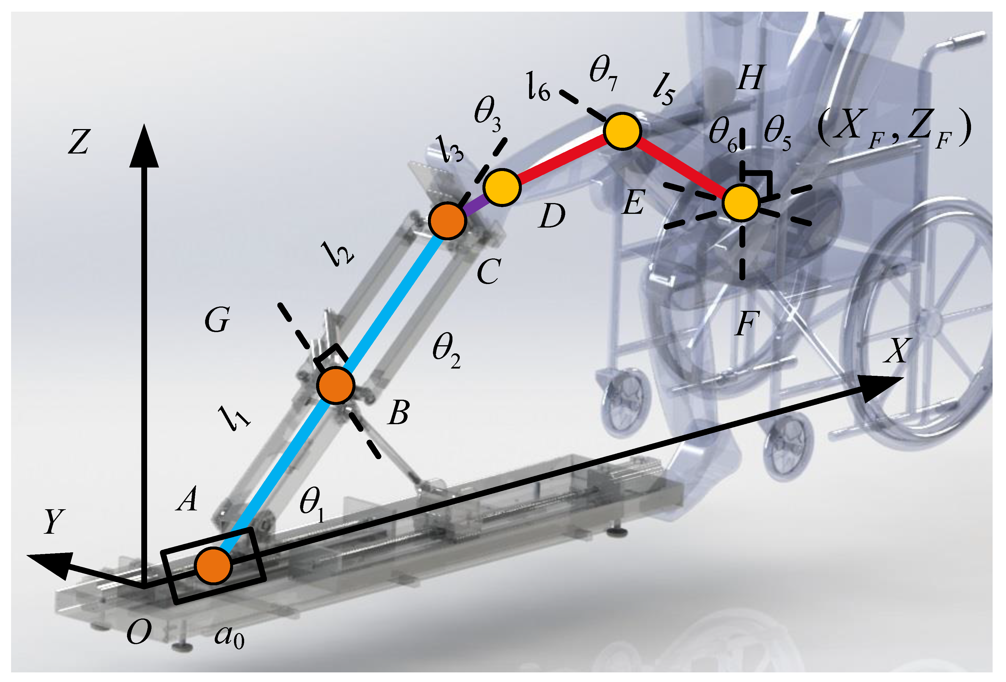
The human-robot hybrid kinematic model could be simplified as a slider-bar linkage as shown in Figure 4. The parallel mechanism of the main motion module is equivalent to a PR mechanism (AB), and the parallelogram mechanism could be regarded as a link (BC). D, E and F represent the ankle, knee and hip joints of the user. As the user’s foot is tied to the foot pedal of the ankle motion module, the linear displacement extending from the ankle joint (D) to the support shaft (C) could be regarded as a link (CD). The lower limb is equivalent to a passive UR mechanism (EFD), which could rotate in the plane .
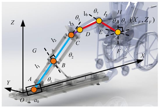
Figure 4.
Human-robot hybrid kinematic model.
The represents the linear displacement of the movable base; , and are joint angles of the robot; and represent the A/A angle and the F/E angle of the human hip joint; represents the F/E angle of the human knee joint. is the rotation angle of (GB as an axis), and is the rotation angle of (HF as an axis). and are the link lengths of the robot; is the length between the point C and D; and are the lengths of the human thigh and crus; and represent the position of the human hip in the coordinate system . In addition, the lower limb length of the user, the height from the foot sole to the ankle joint and the position of the hip should be measured before training.
3.2. Forward/Inverse Kinematics
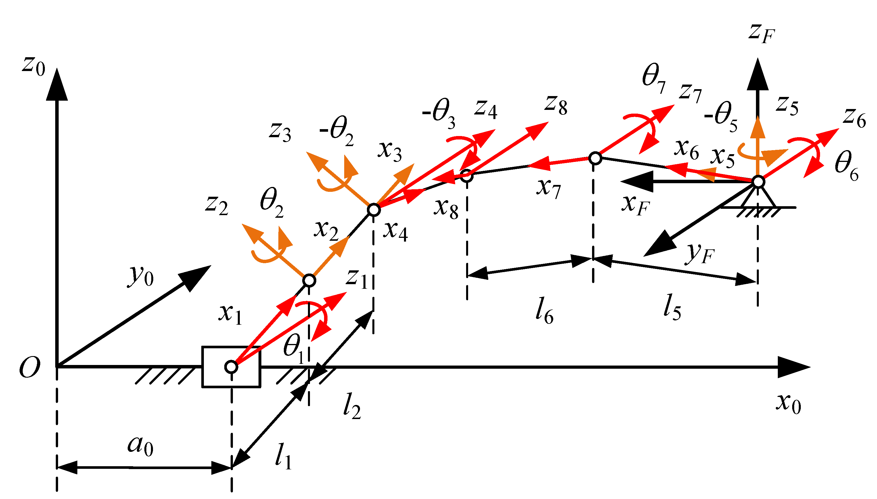
The human-robot hybrid linkage coordinate system is built as shown in Figure 5; the global coordinate system is located on the far end of the main ball screw while the plane is parallel to the sagittal plane. The linkage chain is divided into the linkage ABC and the linkage FED (right leg), and the forward/inverse kinematics of two parts are solved through the Denavit-Hartenberg (D-H) method in the global coordinate system .
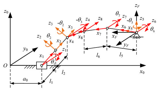
Figure 5.
Human-robot hybrid linkage coordinate system.
As the shape change of the parallelogram mechanism cannot change the relative direction of the opposite link, the coordinate transformation of is divided into and . The D-H parameters of the linkage ABC are listed in Table 2. The directions of , and are defined against the arrow directions shown in Figure 5.

Table 2.
Denavit-Hartenberg (D-H) parameters of the linkage ABC.
The transformation matrix , which represents the coordinate transformation from frame to , is obtained from Equation (1):
where and . The coordinate that transforms from to is calculated as follows:
where represents the rotation angle; is the linear sliding motion of the prismatic joint. The forward/inverse kinematics of the linkage ABC could be expressed as and Equation (3):
Similarly, the transformation of the linkage FED could be calculated using the D-H parameters in Table 3. To analyze the linkage ABC and the linkage FED in one coordinate system, a coordinate transformation matrix between with is built. The forward/inverse kinematics of the linkage FED is expressed as follows:
where

Table 3.
D-H parameters of the linkage FED.
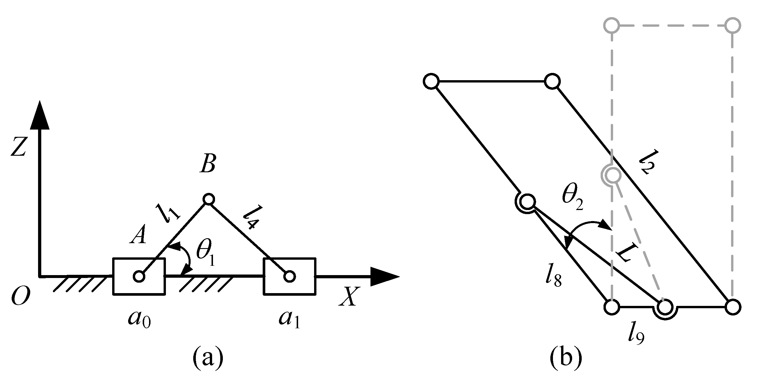
In addition, the is actually controlled by two linear displacements ( and ) as shown in Figure 6a. shown in Figure 6b is determined, and depends on the length L of the linear actuator. The linear displacements ( and L) are calculated as follows:
where is the link length of the subsidiary link; and depend on the position of the linear actuator.
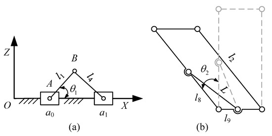
Figure 6.
Parallel mechanism model (a) and parallelogram mechanism model (b).
3.3. Analysis of Human Joints
The linear displacement extending from the user ankle joint to the last mechanical revolution joint is regarded as link , and the human ankle is regarded as a passive spherical joint. Based on the end point positions of the mechanism linkage ABC and the lower limb linkage FED, the connection of the two linkages could be built as follows:
Substituting the mechanism/human joint angular position information into Equation (8), the other joint angular position information could be obtained. Doctors could formulate the training trajectory depending on the joint ROM of patients; the motions of the patient’s joints could be calculated and shown to doctors during the training.
3.4. Velocity Analysis
The end effector velocity can be obtained from mechanical joint velocities through the Jacobian matrix, as in Equation (9):
where represents the joint velocities; and are the linear and angular velocities of the end effector; (linear) and (angular) represent the velocity connections between the joint and the end effector. The and could be calculated from Equation (10):
where is the transpose of the rotation matrix in ; is the position vector in ; and are linear and angular velocities in frame ; is the skew-symmetric matrix related to , and it is shown as:
As and are the same variables for , and could be combined together. Finally, is calculated as:
3.5. Kinematic Simulation of Mechanism Model
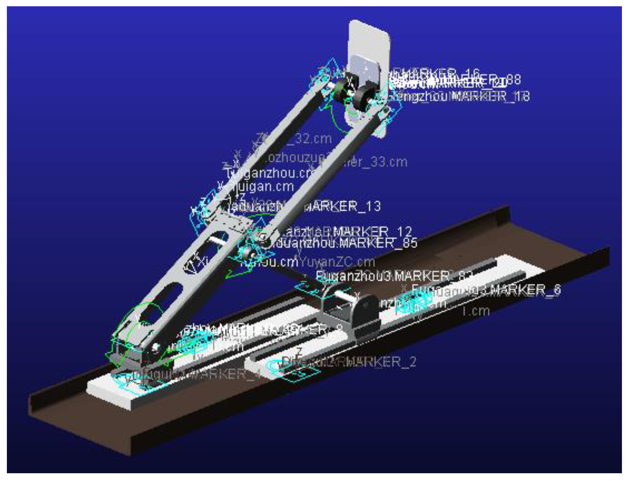
To verify the kinematic equation solving, a verification based on the simulation model is conducted in the software Automatic Dynamic Analysis of Mechanical Systems (ADAMS) as shown in Figure 7. The main steps include inputting the model, adding constraints and setting the drive equations. The joint initial positions are , and the initial position of the end effector is (1019.7, 167.6, 777). The drive equations are given as follows.
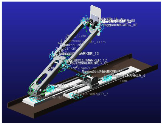
Figure 7.
Simulation model in Automatic Dynamic Analysis of Mechanical Systems (ADAMS).
After setting the other relative parameters, the displacement and velocity of the end point could be simulated through the software. Alternately, the end point motion information could be calculated by substituting the joint information into kinematic equations. Two sets of end point motion results are shown in Figure 8. Comparing two curves of the end point motions, it could be found that kinematic calculation results are largely in agreement with simulation results from ADAMS. The calculation of the kinematic equation solving is verified.

Figure 8.
Three axis comparisons of end point motion results.
4. Trajectory Planning
4.1. Human-Robot Workspace
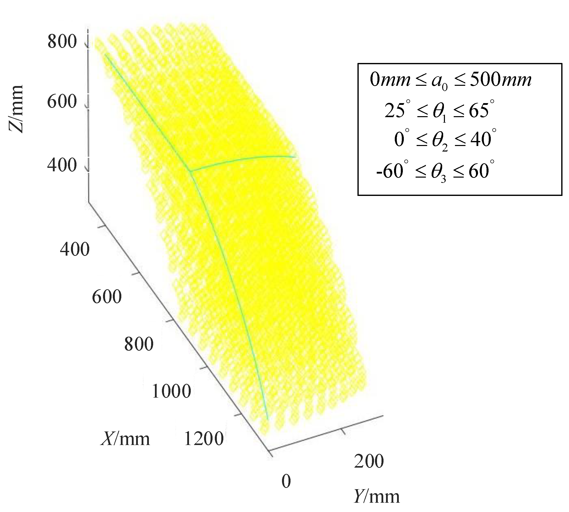
Before planning the training trajectory, the workspace of the robot needs to be determined. The workspace refers to the spatial point set of the end effector, which represents the activity scope of the robots. As a virtual link (l3) is assumed between the robot and the human in the kinematic analysis of Section 3, the human ankle joint (point D) is regarded as the mechanism end point in the workspace analysis. The workspace is analyzed with the numerical method, and the robot workspace is a hexahedron as shown in Figure 9. Substituting the extreme value of each joint into the forward kinematic, and workspace boundaries of the robot could be determined.
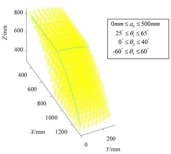
Figure 9.
The spatial workspace of the robot.
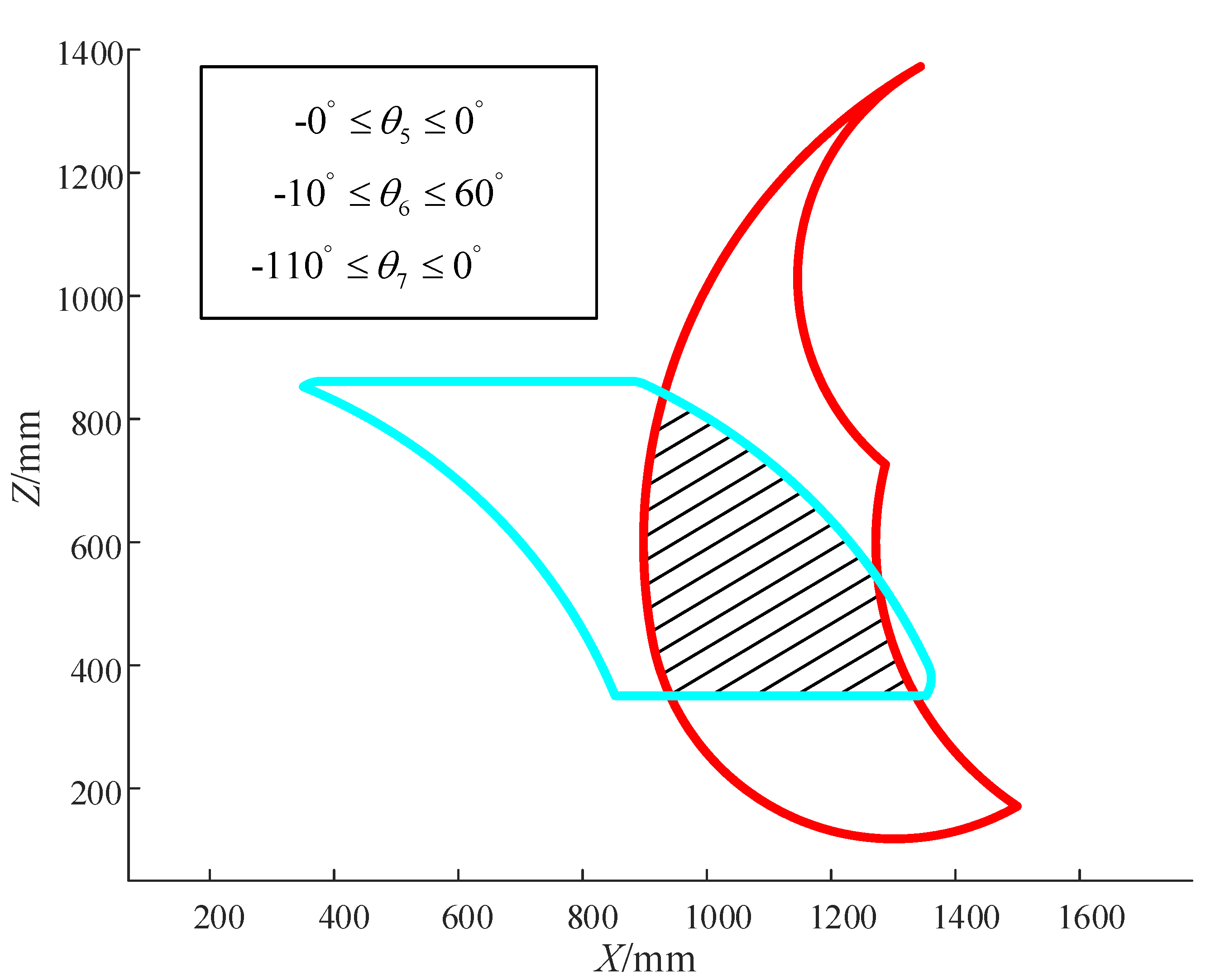
In effect, the robot workspace could not directly be applied for the training planning due to the limited range of human joint motions. The intersection of the robot workspace and the lower limb motion space is feasible for the training planning. Besides, patients with different limb lengths and joint ROM own different motion spaces; therefore, the stable workspace is not suitable for each patient. To guarantee the patient’s safety and to avoid secondary damage, a variable human-robot workspace is proposed.
The variable human-robot workspace is the overlapping part of two spaces, and it is changed depending on different parameters of the human limb. Figure 10 shows a situation of the sagittal training, and the variable human-robot workspace is the shadow part. The hip joint positions (XF and ZF) are set as 1790 mm and 600 mm. The lengths of the human thigh (l5) and crus (l6) are 396 mm and 496 mm.
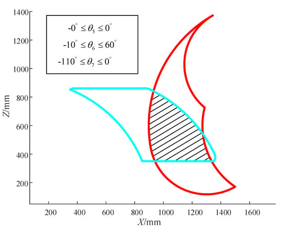
Figure 10.
The variable human-robot workspace.
4.2. Trajectory Planning Mehthod
Two methods for the trajectory planning are presented in this section. One is formulating the trajectory in the human-robot workspace directly, and then calculating the mechanical joint motions through the inverse kinematic. The other is inputting the patient’s joint information, including the ROM and the training speed; the next step is constructing the trajectory and then calculating the mechanical joint motions. Two kinds of the training trajectories planned by two methods are shown in Figure 11 and Figure 12.
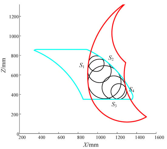
Figure 11.
Circle training trajectory.
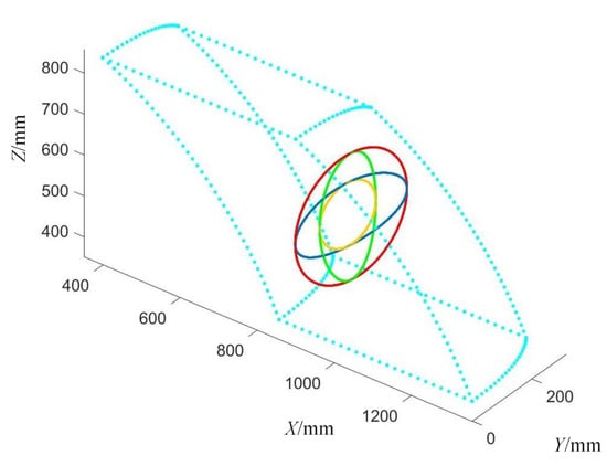
Figure 12.
Spherical ellipse training trajectory.
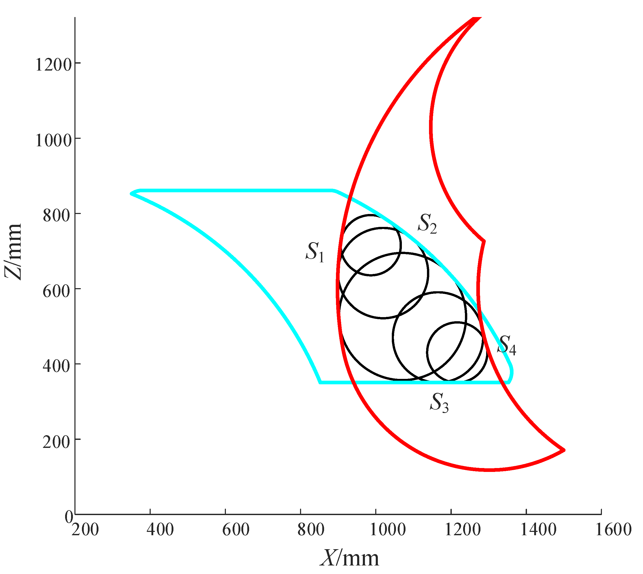
The circle training trajectory is applied in the sagittal multiple joint training, which is calculated by the first method. The main approach is calculating the typical incircles of the workspace boundaries, and other circles could be obtained by modifying the typical circles. The position of the incircle center could be obtained from Equation (14), and the circle trajectory is expressed as Equation (15).
where and represent the center position of the trajectory circle; is the radius of the trajectory circle. and () represent the center position of boundary arcs; () represents the radius of boundary arcs. represents the angular velocity of the trajectory circle, and represents time.
Because there are multiple inverse position solutions of the robot mechanism model, the single position planning cannot meet the requirement for all joints. Therefore, it is necessary to add the angle () planning of the end effector. The main principle is remaining the absolute angle value of the end effector in a lower degree to guarantee the human joints are trained in safe range.
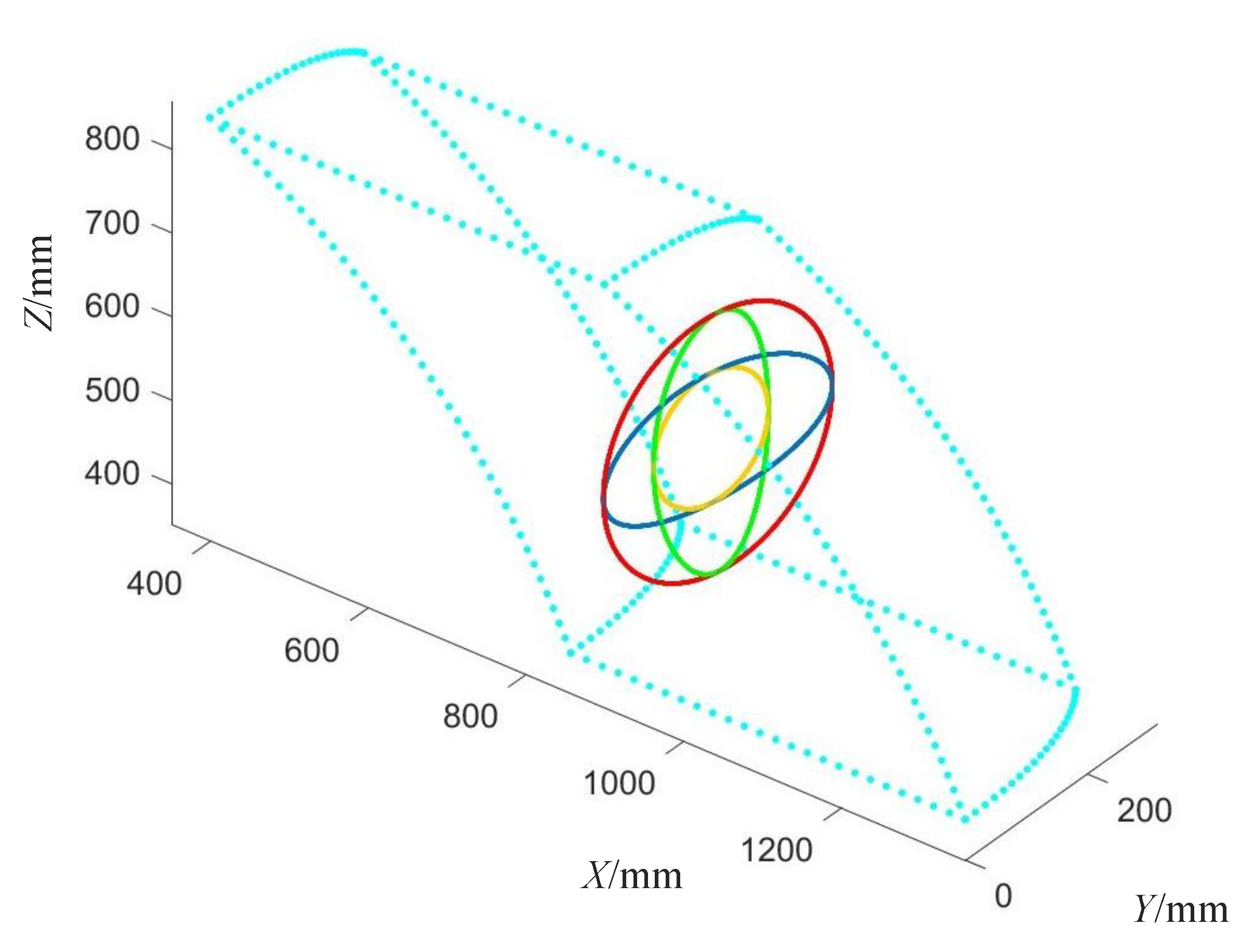
The spherical ellipse training trajectory is used for the hip circumduction rehabilitation, and it is planned depending on the patient’s joint ROM through the second method. To guarantee the training effect of the hip joint, the patient’s leg is left straight in the circumduction training. The rotation center could be calculated from the simplified Equation (4) by inputting the joint angle ( and ) ranges of the hip joint, and the trajectory of the human ankle could be built as follows:
where , and represent the rotation center position of the trajectory; represents the average value of the joint angle range. and refer to the major semi-axis and minor semi-axis of the ellipse trajectory, which are related to joint angle ranges.
As the second method firstly considers the human joint ranges, the final trajectory should be checked and modified to avoid exceeding the robot workspace. Each final trajectory calculated from two methods is divided into a set of multitude points by the numerical method. The position of the trajectory points could be obtained directly from the trajectory analytical formula; the velocity and acceleration between every point are planned to make the speed smooth. The mechanical joint motions could be calculated from the position array of points by inverse solving. Then, the motor control commands could be determined from mechanical joint motions. The semi-close loop position control is selected in the trajectory tracking experiment, and it is more suitable than other controls in this accurate trajectory training.
To guarantee the patient’s safety, a human joint check function is built. It could verify and display the human joint angle through the kinematic calculations. If the angle exceeds the preset or limitation value, it would stop the training to avoid the secondary damage. Training trajectories provided by this robot include the circle, straight, curve, helix and other spatial trajectories. Because the methods are almost same, no more details are shown in this section.
5. Prototype Experiment
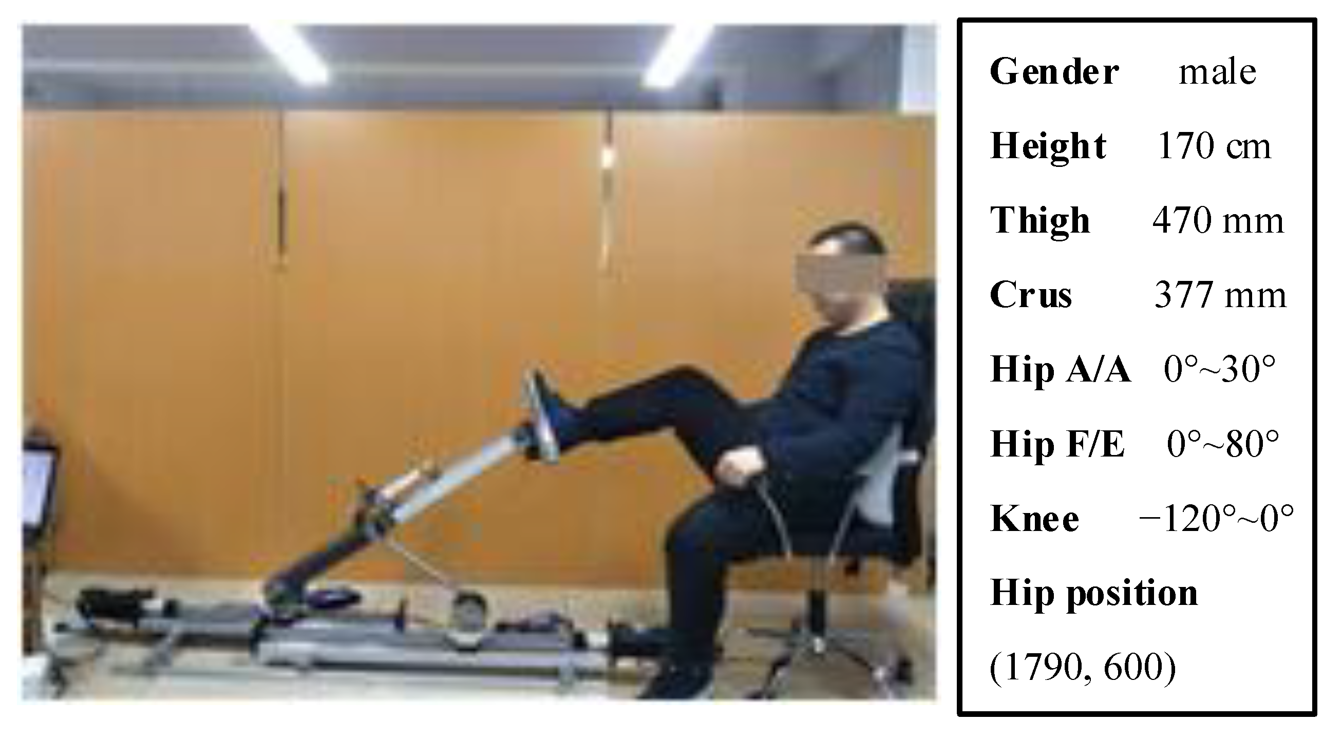
In this section, trajectory tracking experiments were conducted to verify the trajectory planning and the human joint analysis method. A healthy subject was selected to associate the experiment, and the informed consent was confirmed and signed by the subject before the experiment. The prototype of this robot and relative parameters are shown in Figure 13.
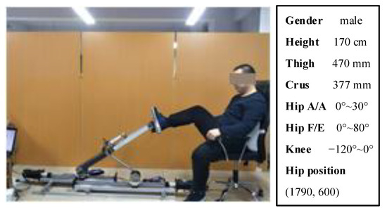
Figure 13.
Prototype of the robot and relative experiment parameters.
The subject parameters were inputted into the control system, and the adaptive workspace could be created. The right leg of the subject was remained relaxed, and the right foot was fixed to the robot pedal. Two 3-axis absolute angle sensors were tied to the thigh and crus of the subject, which were used for detecting angle displacements of subject joints. Two passive trainings including the circle training and spherical ellipse training were conducted in this experiment. Each training was run for five cycles; the recorded data were taken for average processing and then were drawn into figures by MATLAB.
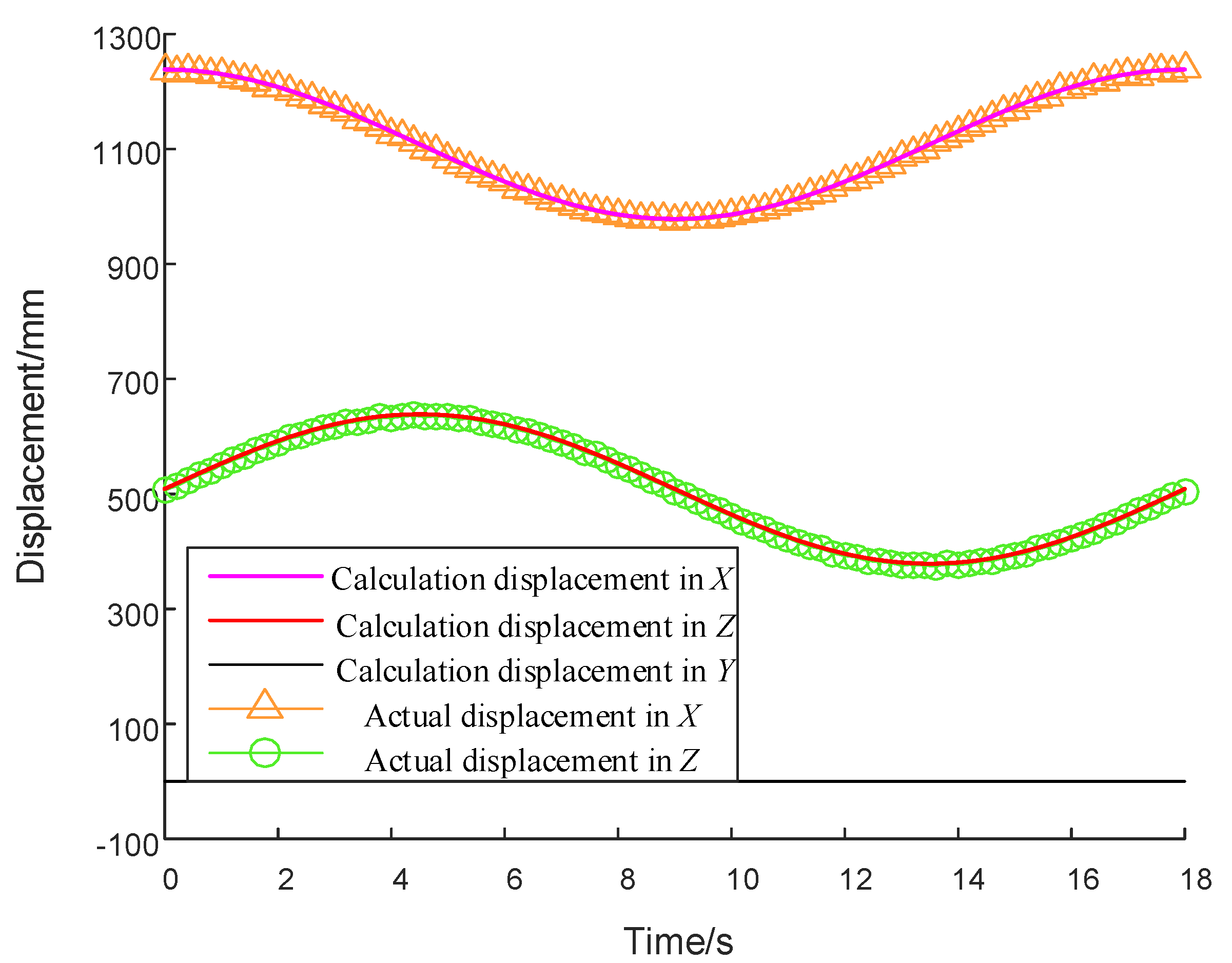
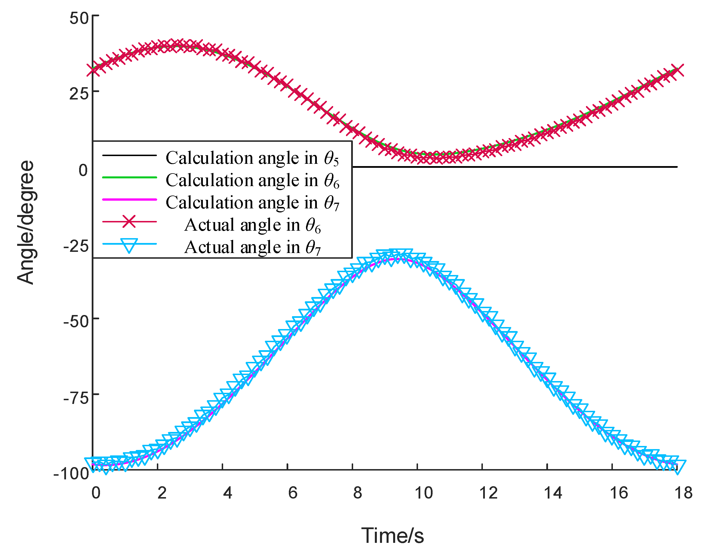
The circle trajectory was modified based on the maximum incircle of the S1, S2 and S3 boundary arcs, which could be described through Equations (14) and (15). The circle center position was (1108.3, 0, 508.7), and the radius was 130 mm. The angular velocity was set as 0.11π rad/s. The end point position theoretical calculation and the human joint angle theoretical calculation are shown in Figure 14 and Figure 15. The actual positions of the end point could be obtained through angle sensors and encoders, and the actual angles of the human joints were detected by sensors tied to the subject’s leg. Experimental results are also shown in Figure 14 and Figure 15. The end point maximum displacement errors between the calculation and the experiment were 5.46 mm and 4.84 mm in the X- and Z-axes, and the human joint angle maximum displacement errors between the calculation and the experiment were 1.45° and 1.99° in and .
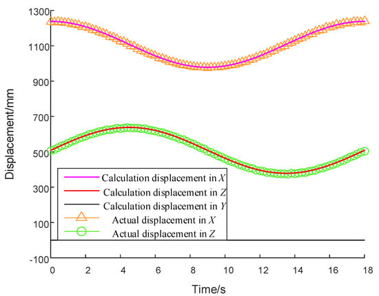
Figure 14.
Comparisons of displacements between the theoretical and the experiment.
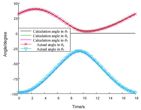
Figure 15.
Comparisons of angles between the theoretical and the experiment.
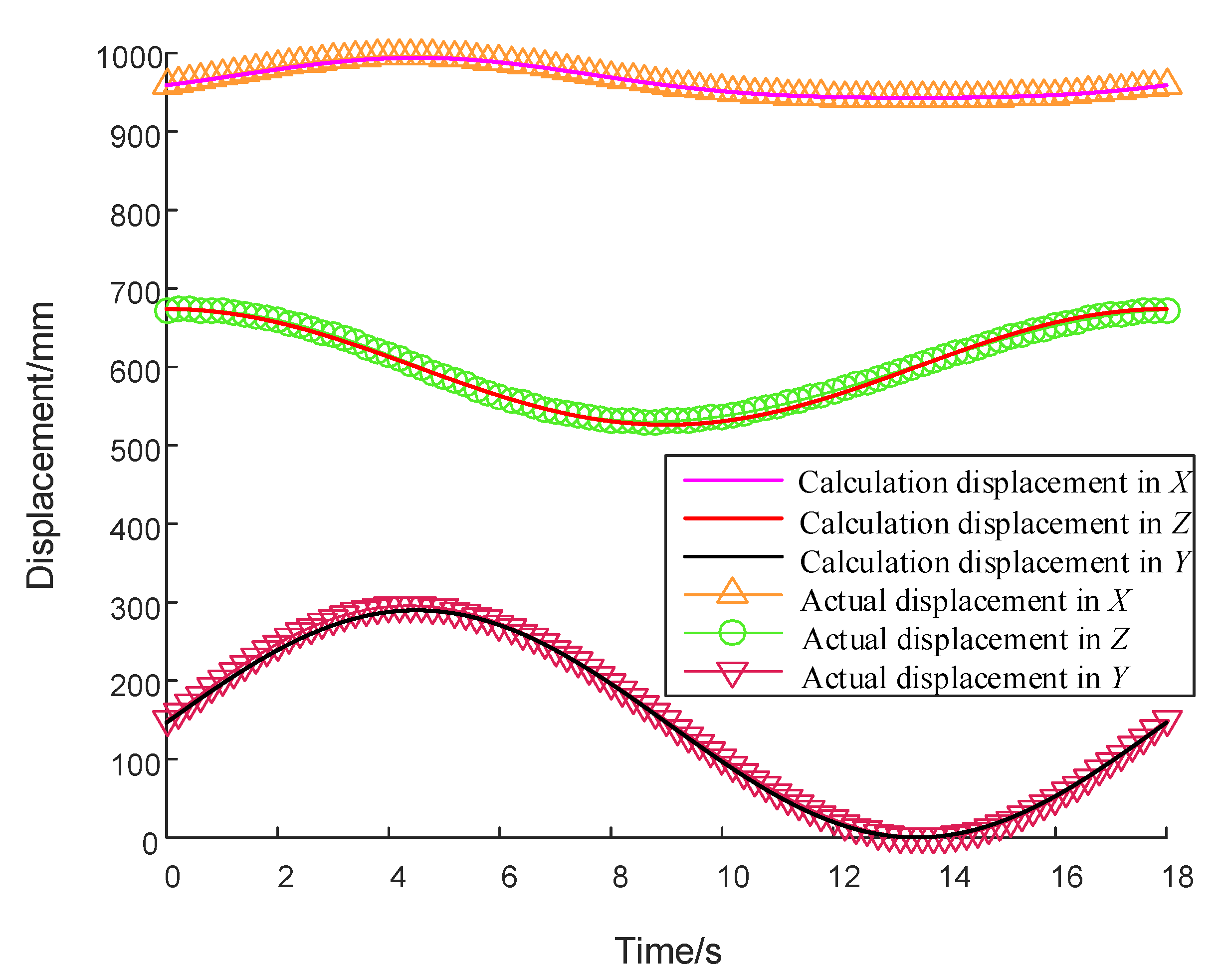
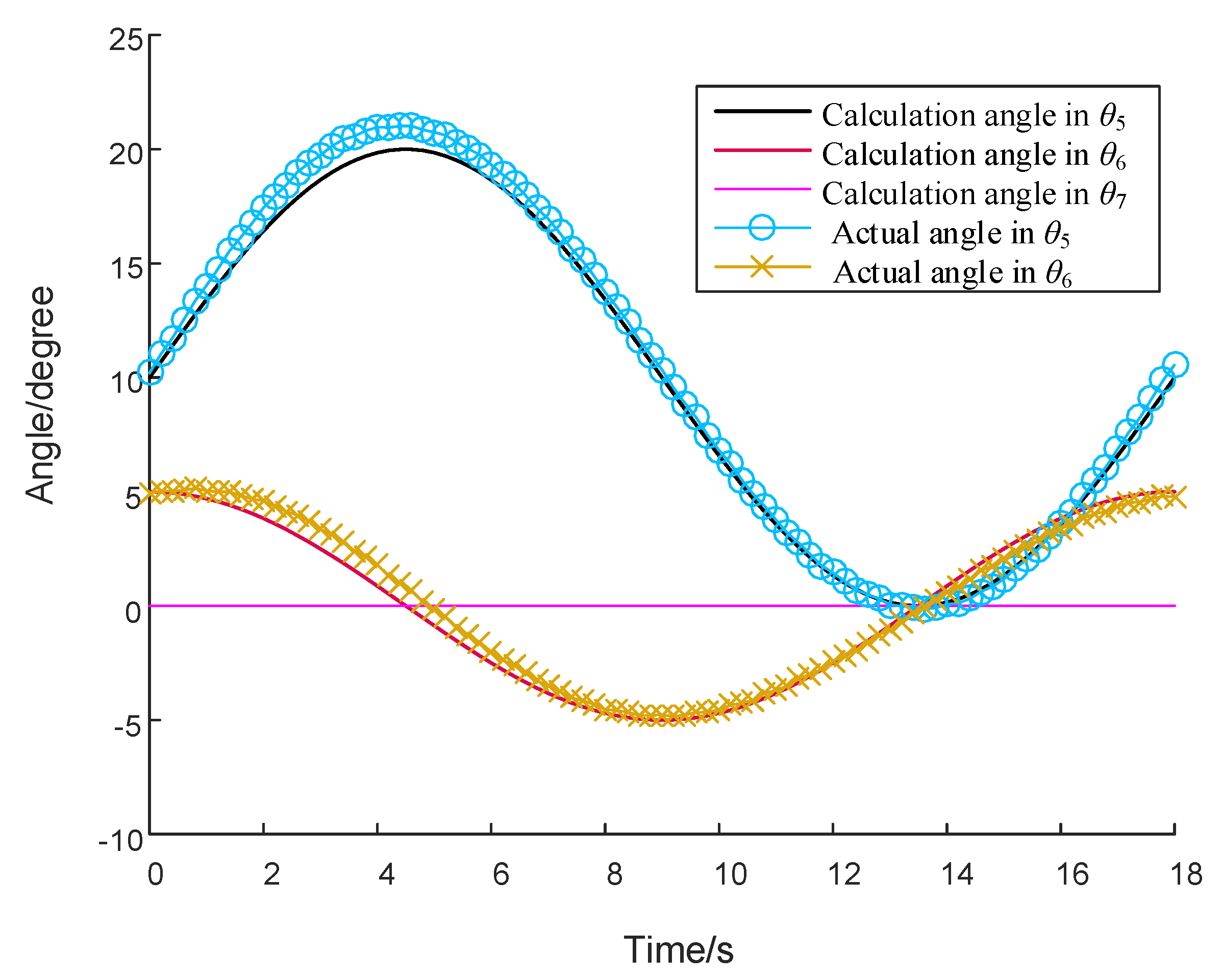
The spherical ellipse trajectory is planned depending on the training requirement and the patient’s ROM, and it is mainly used for the circumduction training. The spherical ellipse trajectory could be described through Equations (16) and (17). The training range of the hip A/A was set from 0° to 20°; the range of the hip F/E was set from −5° to 5°; the angular velocity was set as 0.11π rad/s. The comparisons of the end point positions and human joint angles are shown in Figure 16 and Figure 17. The end point maximum displacement errors between the calculation and the experiment were 3.01 mm, 5.46 mm and 4.19 mm in the X-, Y- and Z-axes, and the human joint angle maximum displacement errors between the calculation and the experiment were 0.94° and 1.15° in and .
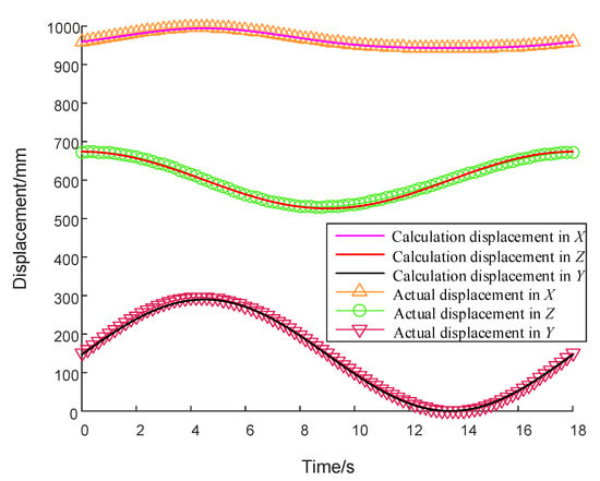
Figure 16.
Comparisons of displacements between the theoretical and the experiment.
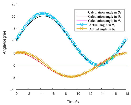
Figure 17.
Comparisons of angles between the theoretical and the experiment.
6. Discussion
Figure 14 and Figure 16 show that the trajectory errors between the calculation and the experiment are at a low level, so the result could prove that this robot has a great capability and could provide accurate trajectory motions. From Figure 15 and Figure 17, it could be found that the actual human joint motions have the same pattern to theoretical calculations. Compared to manual rehabilitation, the error is in the acceptable range. The experiment results indicate that this robot has a good performance in hip A/A and sagittal trainings. This robot could acquire the valid information of patient’s joint motions in training, and doctors could design the training depending on the patient’s joint ROM through the robot. Therefore, it is feasible to regard this robot as an alternative solution to the traditional lower rehabilitation.
Rehabilitation medicine is a wide subject, and it is mainly divided into neurological rehabilitation (stroke) and orthopedic rehabilitation (surgery). There are both similarities and differences between the two kinds of rehabilitations, and this device mainly targets stroke patients to help the patient in avoiding limb physical-motor disability. In the future, more training functions for stroke would be studied based on clinical applications.
In the kinematic model of the lower limb, the ankle joint motion is not fully considered. This issue is regarded as the main source of human joint errors. Meanwhile, the behavior of the A/A training is not very well when the leg is not straight. The little axial rotation of the leg is the main reason of this situation. These problems would be investigated in the future work.
7. Conclusions
A 4-DOF serial-parallel hybrid lower limb rehabilitation robot with the spatial workspace is introduced in this article. The mechanism characters of this robot are the simple structure and the small size, and the patient could directly do training from a wheelchair without patient handling. The training movements of this robot include the hip A/A movement and F/E movements of three lower joints. To guarantee the joint ROM, a method for acquiring the human joint motions is proposed. This analysis method is based on a human-robot hybrid kinematic model. The joint motion information could be used in the training detection and the trajectory planning. Two kinds of trajectory planning methods in a variable human-robot workspace are introduced. Finally, the trajectory tracking experiment of the prototype approves the accuracy of the robot trajectory planning and the feasibility of the human joint analysis method. This robot could be a low-cost alternative solution for manual rehabilitation because of the capability of training behaviors, and it has a good potential to be applied in hospitals or nursing homes.
Author Contributions
Conceptualization, H.W. and M.L.; methodology, Z.J. and H.Y.; software, X.H.; prototype and experiment, G.L. and S.L.; writing—original draft preparation, M.L.; writing—review and editing, H.W. All authors have read and agreed to the published version of the manuscript.
Funding
This research was funded by National key research and development program (2019YFB1312500), National Natural Science Foundation of China (U1913216), Key research and development plan of Hebei Province, China (19211820D), Shanghai Science and Technology Innovation Action Plan (19441908200).
Conflicts of Interest
The authors declare no conflict of interest.
References
- Tyson, S.F.; Hanley, M.; Chillala, J.; Selley, A.; Tallis, R.C. Balance disability after stroke. Phys. Ther. 2006, 86, 30–38. [Google Scholar] [CrossRef] [PubMed]
- Munyombwe, T.; Hill, K.M.; Knapp, P.; West, R.M. Mixture modelling analysis of one-month disability after stroke: Stroke outcomes study (SOS1). Qual. Life Res. 2014, 23, 2267–2275. [Google Scholar] [CrossRef]
- Zhang, X.; Yue, Z.; Wang, J. Robotics in Lower-Limb Rehabilitation after Stroke. Behav. Neurol. 2017, 2017, 1–13. [Google Scholar] [CrossRef]
- Ochi, M.; Wada, F.; Saeki, S.; Hachisuka, K. Gait training in subacute non-ambulatory stroke patients using a full weight-bearing gait-assistance robot: A prospective, randomized, open, blinded-endpoint trial. J. Neurol. Sci. 2015, 353, 130–136. [Google Scholar] [CrossRef] [PubMed]
- Mazzoleni, S.; Puzzolante, L.; Zollo, L.; Dario, P.; Posteraro, F. Mechanisms of motor recovery in chronic and subacute stroke patients following a robot-aided training. IEEE Trans. Haptics 2014, 7, 175–180. [Google Scholar] [CrossRef] [PubMed]
- Yoo, D.H.; Kim, S.Y. Effects of upper limb robot-assisted therapy in the rehabilitation of stroke patients. J. Phys. Ther. Sci. 2015, 27, 677–679. [Google Scholar] [CrossRef] [PubMed]
- Aprile, I.; Iacovelli, C.; Goffredo, M.; Cruciani, A.; Galli, M.; Simbolotti, C.; Pecchioli, C.; Padua, L.; Galafate, D.; Pournajaf, S.; et al. Efficacy of end-effector Robot-Assisted Gait Training in subacute stroke patients: Clinical and gait outcomes from a pilot bi-centre study. NeuroRehabilitation 2019, 45, 201–212. [Google Scholar] [CrossRef]
- Azcaray, H.; Blanco, A.; García, C.; Adam, M.; Reyes, J.; Guerrero, G.; Guzmán, C. Robust GPI Control of a New Parallel Rehabilitation Robot of Lower Extremities. Int. J. Control. Autom. Syst. 2018, 16, 2384–2392. [Google Scholar] [CrossRef]
- Bingjing, G.; Jianhai, H.; Xiangpan, L.; Lin, Y. Human–robot interactive control based on reinforcement learning for gait rehabilitation training robot. Int. J. Adv. Robot. Syst. 2019, 16, 1–16. [Google Scholar] [CrossRef]
- Goergen, R.; Valdiero, A.C.; Rasia, L.A.; Oberdorfer, M.; de Souza, J.P.; Goncalves, R.S. Development of a Pneumatic Exoskeleton Robot for Lower Limb Rehabilitation. In Proceedings of the 2019 IEEE 16th International Conference on Rehabilitation Robotics, Toronto, ON, Canada; 24 June 2019; pp. 187–192. [Google Scholar]
- Vantilt, J.; Tanghe, K.; Afschrift, M.; Bruijnes, A.K.; Junius, K.; Geeroms, J.; Aertbeliën, E.; De Groote, F.; Lefeber, D.; Jonkers, I.; et al. Model-based control for exoskeletons with series elastic actuators evaluated on sit-to-stand movements. J. Neuroeng. Rehabil. 2019, 16, 1–21. [Google Scholar] [CrossRef]
- Urendes, E.; Asin-Prieto, G.; Ceres, R.; Garcia-Carmona, R.; Raya, R.; L Pons, J. HYBRID: Ambulatory Robotic Gait Trainer with Movement Induction and Partial Weight Support. Sensors 2019, 19, 4773. [Google Scholar] [CrossRef] [PubMed]
- Kim, J.-Y.; Cho, B.-K. Development of a Lower Limb Exoskeleton Worn on the Front of a Human. J. Intell. Robot. Syst. 2019, 96, 49–64. [Google Scholar] [CrossRef]
- De Luca, A.; Bellitto, A.; Mandraccia, S.; Marchesi, G.; Pellegrino, L.; Coscia, M.; Leoncini, C.; Rossi, L.; Gamba, S.; Massone, A.; et al. Exoskeleton for Gait Rehabilitation: Effects of Assistance, Mechanical Structure, and Walking Aids on Muscle Activations. Appl. Sci. 2019, 9, 2868. [Google Scholar] [CrossRef]
- Dao, Q.-T.; Yamamoto, S.-I. Assist-As-Needed Control of a Robotic Orthosis Actuated by Pneumatic Artificial Muscle for Gait Rehabilitation. Appl. Sci. 2018, 8, 499. [Google Scholar] [CrossRef]
- Eiammanussakul, T.; Sangveraphunsiri, V. A Lower Limb Rehabilitation Robot in Sitting Position with a Review of Training Activities. J. Healthc Eng. 2018, 2018, 1–18. [Google Scholar] [CrossRef]
- Feng, Y.; Wang, H.; Vladareanu, L.; Chen, Z.; Jin, D. New Motion Intention Acquisition Method of Lower Limb Rehabilitation Robot Based on Static Torque Sensors. Sensors (Basel) 2019, 19, 3439. [Google Scholar] [CrossRef]
- Xu, J.; Liu, Y.; Chen, J.; Li, Y.; Xu, L.; Peng, C.; Chen, S.; Liu, J.; Xu, C.; Cheng, G.; et al. A Multi-Mode Rehabilitation Robot With Magnetorheological Actuators Based on Human Motion Intention Estimation. IEEE Trans. Neural Syst. Rehabil. Eng. 2019, 27, 2216–2228. [Google Scholar] [CrossRef]
- Wang, K.-Y.; Yin, P.-C.; Yang, H.-P.; Tang, X.-Q. The man-machine motion planning of rigid-flexible hybrid lower limb rehabilitation robot. Adv. Mech. Eng. 2018, 10, 1–11. [Google Scholar] [CrossRef]
- Zhang, F.; Hou, Z.G.; Cheng, L.; Wang, W.Q.; Chen, Y.X.; Hu, J.; Peng, L.; Wang, H.B. ILeg- A Lower Limb Rehabilitation Robot: A Proof of Concept. IEEE Trans. Hum. Mach. Syst. 2016, 46, 761–768. [Google Scholar] [CrossRef]
- Yan, H.; Wang, H.; Vladareanu, L.; Lin, M.; Vladareanu, V.; Li, Y. Detection of Participation and Training Task Difficulty Applied to the Multi-Sensor Systems of Rehabilitation Robots. Sensors 2019, 19, 4681. [Google Scholar] [CrossRef]
- Guzmán-Valdivia, C.H.; Blanco-Ortega, A.; Oliver-Salazar, M.A.; Gómez-Becerra, F.A.; Carrera-Escobedo, J.L. HipBot—The design, development and control of a therapeutic robot for hip rehabilitation. Mechatronics 2015, 30, 55–64. [Google Scholar] [CrossRef]
- Meng, W.; Xie, S.Q.; Liu, Q.; Lu, C.Z.; Ai, Q. Robust Iterative Feedback Tuning Control of a Compliant Rehabilitation Robot for Repetitive Ankle Training. IEEE/ASME Trans. Mechatron. 2017, 22, 173–184. [Google Scholar] [CrossRef]
- Ayas, M.S.; Altas, I.H. Fuzzy logic based adaptive admittance control of a redundantly actuated ankle rehabilitation robot. Control. Eng. Pract. 2017, 59, 44–54. [Google Scholar] [CrossRef]
- Vallés, M.; Cazalilla, J.; Valera, Á.; Mata, V.; Page, Á.; Díaz-Rodríguez, M. A 3-PRS parallel manipulator for ankle rehabilitation: Towards a low-cost robotic rehabilitation. Robotica 2015, 35, 1939–1957. [Google Scholar] [CrossRef]
- Liao, Z.; Yao, L.; Lu, Z.; Zhang, J. Screw theory based mathematical modeling and kinematic analysis of a novel ankle rehabilitation robot with a constrained 3-PSP mechanism topology. Int. J. Intell. Robot. Appl. 2018, 2, 351–360. [Google Scholar] [CrossRef] [PubMed]
- Jamwal, P.K.; Hussain, S. Design optimization of a cable actuated parallel ankle rehabilitation robot: A fuzzy based multi-objective evolutionary approach. J. Intell. Fuzzy Syst. 2016, 31, 1897–1908. [Google Scholar] [CrossRef]
- AminiAzar, W.; Akbarimajd, A.; Parvari, E. Intelligent Control Method of a 6-DOF parallel robot Used for Rehabilitation Treatment in lower limbs. Automatika 2016, 57, 466–476. [Google Scholar]
- Rakhodaei, H.; Saadat, M.; Rastegarpanah, A.; Abdullah, C.Z. Path planning of the hybrid parallel robot for ankle rehabilitation. Robotica 2014, 34, 173–184. [Google Scholar] [CrossRef]
- Wahoff, M.; Ryan, M. Rehabilitation after hip femoroacetabular impingement arthroscopy. Clin. Sports Med. 2011, 30, 463–482. [Google Scholar] [CrossRef]
- Willimon, S.C.; Briggs, K.K.; Philippon, M.J. Intra-articular adhesions following hip arthroscopy: A risk factor analysis. Knee Surg. Sports Traumatol. Arthrosc. 2013, 22, 822–825. [Google Scholar] [CrossRef]
- Coleman, E.R.; Moudgal, R.; Lang, K.; Hyacinth, H.I.; Awosika, O.O.; Kissela, B.M.; Feng, W. Early Rehabilitation After Stroke: A Narrative Review. Curr. Atheroscler. Rep. 2017, 19, 59. [Google Scholar] [CrossRef] [PubMed]
© 2020 by the authors. Licensee MDPI, Basel, Switzerland. This article is an open access article distributed under the terms and conditions of the Creative Commons Attribution (CC BY) license (http://creativecommons.org/licenses/by/4.0/).

