Abstract
This investigation shows a traditional and advanced exergetic assessment of a waste heat recovery system based on recuperative ORC (organic Rankine cycle) as bottoming cycle of a 2 MW natural gas internal combustion engine. The advanced exergetic evaluation divides the study into two groups, the avoidable and unavoidable group and the endogenous and exogenous group. The first group provides information on the efficiency improvement potential of the components, and the second group determines the interaction between the components. A sensitivity analysis was achieved to assess the effect of condensing temperature, evaporator pinch, and pressure ratio with net power, thermal efficiencies, and exergetic efficiency for pentane, hexane, and octane as organic working fluids, where pentane obtained better energy and exergetic results. Furthermore, an advanced exergetic analysis showed that the components that had possibilities of improvement were the evaporator (19.14 kW) and the turbine (8.35 kW). Therefore, through the application of advanced exergetic analysis, strategies and opportunities for growth in the thermodynamic performance of the system can be identified through the avoidable percentage of destruction of exergy in components.
1. Introduction
Given the current high energy demand, improvements of waste-to-energy conversion systems are necessary to promote the rational use of energy and environmental preservation. The human population is growing, and as a consequence, the energy sector needs to meet the increasing demand. In addition, the generation of electricity from materials such as coal, oil, among others, leads to severe damage to the environment, not to mention the fact that these resources are limited [1]. Therefore, some waste heat recovery systems such as bottoming cycles have been studied to increase the global energy efficiency of the power generation process [2].
Organic Rankine cycle (ORC) systems are appropriate for this type of use, due to their ability to recover heat in low-temperature applications and the option of implementing them in lower capacity decentralized power plants [3], as well as, if widely applied in industry, ORC systems should contribute to the global trend in energy efficiency and greenhouse gas emissions. According to the energy consumption trend, by 2050, an increase of 70% in worldwide energy demands and an increase of 60% in greenhouse gas emissions are predicted related to 2011. Related to emissions and their consequences, by 2050, the global temperature is predicted to increase by 6 °C and, potentially, would have devastating impacts such as climate change, energy security, as well as an unsustainable future [4]. More specifically, about half of the energy consumed in the world is wasted in heat because of the limitations of energy conversion processes [5].
ORC is a cost-effective waste-to-energy technology oriented to produce energy from various thermal sources such as biomass, solar [6,7], geothermal, or waste heat recovery (WHR) available from industrial processes or internal combustion engines (ICEs) [8,9]. In recent years, ORC technology has gained sufficient global attention because of its adaptability to different heat capacities and source temperatures, and currently, it is the most appropriate technology applied for obtaining thermal energy from external sources by conversion [10]. Typical techniques for developing low-quality heat utilization consist of an energy cycle represented by the ORC and the reverse steam compression cycle represented by the cooling and heating cycle [11].
The ORC has been used to recover waste heat, which is considered to be 50% of the heat produced in industrial processes [12,13]. Solar radiation is among the energy sources that have higher capacity and low maintenance times [14], from which it is possible to obtain thermal energy by conversion of the ocean and solar ponds; these energies are called low-quality energy sources [15]. Due to its use in residential and commercial buildings, ORC technology is an excellent small-scale alternative for the replacement of power generation systems [16], where it is also applicable to the cogeneration of heating and cooling, which is considered to be an advantage in terms of distributed power generation [17]. In power generation applications, the organic Rankine cycle is considered due to modest structure and excellent performance, because it has been found in numerous studies in the literature that ORC improves the energy production of systems that generate waste heat [18,19,20] in addition to low maintenance costs [21].
An ORC operates analogous to a traditional steam cycle system with an organic fluid in place of water [22]. The impacts of some organic fluids on energy efficiency and heat recovery efficiency have been researched, and play a relevant function in the performance of this thermal cycle [23]. However, it is very difficult to find the best organic fluid that adjusts to the system at low source temperatures [24]. Due to international policies related to climate change mitigation and environmental preservation, the use of chlorofluorocarbons (CFCs) has been limited in thermal systems. Thus, selection of the appropriate organic fluid has become a major challenge under study [25].
New fluids with almost zero ozone depletion potential and global warming have begun to be used in these systems as compared with the conventional refrigerants and working fluids that have been used today. Thus, the HFO (hydrofluoroolefin) group refrigerants are currently used as part of fluorinated refrigerants and are substitutes for CFCs. PFCs (perfluorocarbons) are also used to avoid destroying the ozone layer. In this paper, refrigerants from the alkane group were chosen because of their critical favorable conditions at high temperatures [26], in addition to being environmentally friendly, as are siloxanes. HCFCs (hydrochlorofluorocarbons) and CFCs (chlorofluorocarbons) were not considered because of their environmental effects under the Montreal Protocol [27]. HFCs (hydrofluorocarbons) were also excluded under the Kyoto Protocol [28].
The problems produced by the consumption of fossil fuels have led to the search for alternatives, one example being ORC, which is a recommended option for obtaining electricity using low-quality waste heat [29,30]. A rise in the fuel market and the policy of reducing carbon dioxide emissions have created a massive interest in increasing the thermal efficiency of engines, surpassing techniques already in use. The conversion of waste heat from engines has been considered to be an alternative method for generating energy according to the need that is required [31].
The economic profitability of ORC systems as waste heat recovery systems at a medium quality temperature depends very much on the operating parameters, the configuration of the cycle, and the organic fluid that it is going to be used. Therefore, there have been analyses conducted on new methods to improve the selection of these variables. For example, Toffolo et al. [32] proposed a thermodynamic optimization of the system configuration with the primary variable being the design parameters, and analyzed all the possible adjustments and design recommendations according to the objective function and values it offered economic modeling as compared with real costs, and considerations of the behavior of this configuration without the design parameters.
Nishith et al. [33] suggested a simplified methodology for selection according to thermal-economic assessment and a comparative diagram based on working fluids for the power generation cycle. Additionally, Ziviani et al. [21] presented a summary of the problems associated with the modeling of ORC, and provided some strategies to advance an efficient and great simulation tool. Imran et al. [34] showed a thermoeconomic optimization of simple ORC and recuperative ORC for WHR applications, resulting in a 1.01% average increase in thermal efficiency from a simple ORC to a one-stage recuperative ORC, representing an extra expense of $187/kW, whereas, from a simple ORC to a dual-stage recuperative ORC, there was a 1.45% extra increase in thermal efficiency, and an extra expense of 297 $/kW in cost.
Alternatively, Mohammadi et al. [35] conducted a study, using a combination of conventional and advanced exergetic analysis, on a supercritical CO2 recompression cycle to establish the potential for improving the performance of the thermal cycle, in which the maximum optimal potential of the system was 106.85 MW, the overall exergetic efficiency reached 17.13%, and about 35% of exergy destruction could be avoided by focusing on components such as the turbine, the heat exchanger, and the main compressor. In search of improvement potentials in the applications of turbocharged combustion engines, a conventional exergetic study gave the expander and evaporator priority improvement potential, while an advanced exergetic analysis indicated that the pump and expander were a priority, and the destruction of the exergetic cycle could be reduced by 36.5% [36]. Studies with advanced exergy analyses which took into account the recovery of waste heat in geothermal applications, low temperature solar applications, and the recovery of waste heat from exhaust gases of combustion engines, have shown that the exergetic efficiency of ORC improved by 20%, and have proposed that the evaporator, the expander, the pump and the condenser are equipment with significant improvement potential [37].
In addition, El-Emam et al. [38] developed a thermal analyses of a geothermal recuperative ORC, and found that the first and second thermodynamic efficiency values were 16.37% and 48.8%, respectively, when the geothermal water rejection temperature ranged from 78.49 to 116.2 °C. Khaljani et al. [39] considered as objective functions the first and second law efficiencies, and the total system cost rates. The results presented the highest irreversibility in the combustion chamber, followed by the steam heat exchanger and the turbine, respectively, with a full cycle exergy-economic factor of 10.59%, representing an exergy destruction cost value higher than the capital investment cost.
Complementarily, Safarian et al. [40] showed the results of one primary and three modified ORCs and reported that the evaporator made an important contribution to the exergy destroyed, which was reduced by increasing the evaporation pressure. Then, the results corroborated that the combined ORC with the regeneration of the turbine had the highest thermal efficiency (22.8%) and exergy efficiency (35.5%), and the smallest exergy loss (42.2 kW) due to the reduction in cooling thermal demand and an increase in the power output. Li et al. [41] explored the thermal performance of ORC under source temperatures ranging from 100 to 70 °C, and found that with a temperature of 80 °C on the hot side, they were able to achieve a thermal efficiency of 7.4%, and an isentropic turbine efficiency of 68%. The total exergy efficiency of the system was approximately 40%. König-Haagen et al. [42] used energy storage systems (TESS) and the optimization increased the overall exergy efficiency ranging from 36% to 43%. However, they asserted that detailed exergy studies on the optimization potential and the influence of TESS were still lacking.
Heat recovery from diesel engines by means of ORC systems has also aroused research interest. Jannatkhah et al. [43] studied a combined heating, cooling, and power generation system for the recovery of waste heat from the exhaust gases of a diesel engine fed with different fuels and biofuels supplied to the engine at different speeds and loads to evaluate the energy system and exergetically. Ong et al. [44,45] developed studies for the recovery of waste heat from diesel engines in the marine industry. Their studies focused on the recovery of both the waste heat from engine exhaust gases and the waste heat due to the heating of engine cylinder liner cooling water. These two currents were used to evaporate and preheat the ORC working fluid, which they evaluated with the maximum net power output for different working fluids verifying the influence of the preheating temperature on the system performance.
Focusing only on heat recovery from internal combustion engines, Oliveira et al. [46] for example, conducted a technical and economic analysis of waste heat energy recovery from internal combustion engines using the organic Rankine cycle in order to increase the efficiency of electrical productivity. Although heat recovery from internal combustion engines by means of ORC systems has been studied, few advanced exergetic analyses have been developed for these systems. Galindo et al. [36] developed an advanced exergy analysis for an ORC coupled to an internal combustion engine. The parameters of the engine used were obtained from previous work [47] where they used an engine placed on a test bench with the necessary instrumentation to measure the operating parameters of the engine. The engine was an in-line four-cylinder turbocharger with a volumetric capacity of two liters and a maximum power of 153 kW at 5500 rpm and 100% load, as well as a maximum torque of 308 Nm at 3000 rpm and 100% load. With respect to the ORC, the isentropic efficiency of the turbine and compressor was 43% and 89%, respectively, and the pinch point of the condenser and evaporator was 5 and 50 °C, respectively.
There has been no advanced exergetic analysis, including a sensitivity analysis to evaluate the effect of the condensing temperature, the evaporator pinch, and the pressure ratio with the net power, thermal efficiencies, and exergetic efficiency, developed in the literature for an ORC system coupled to a 2 MW internal combustion Jenbacher engine, which is operating in the city of Barranquilla Colombia at a temperature between 30 and 40 °C and a relative humidity of approximately 80%, using pentane, hexane, and octane as working fluids for the ORC system.
Taking into account that approximately 35% of the energy in the combustion process of an ICE is waste from the exhaust gas, there is a need to implement high efficiency energy recovery systems that are easy to implement, with the aim to improve the overall efficiency of these thermal machines, and therefore decrease the carbon footprint. For this reason, an exergetic analysis of the recuperative organic Rankine cycle (RORC) was achieved to determine the exogenous, endogenous, avoidable, and unavoidable exergy destruction of the investigated cycles. This investigation analyzes an energy recovery system based on ORC, studying different work fluids and operating conditions, in order to minimize the generation of entropy, as a key parameter that maximizes the energy recovered and makes possible the massification of this type of technology, increasing its efficiencies. The present article is structured as follows: The Methodology section presents a detailed description of the system and its parameters as well as the approach to perform a traditional and advanced exergetic analysis on the system; the Results and Discussions section presents a parametric study on the effect of pressure ratio, condensing temperature, and evaporator pinch point temperature on thermal and exergy indicators, as well as the operating conditions of the thermal system; and the final section presents the conclusions regarding the results, as well as the recommendations for future studies.
2. Methodology
MATLAB® software was used to perform the energy and exergetic modeling of the natural gas generation engine for waste heat recovery based on ORC with complementary cycles in order to determine which variables were relevant for the development of the model and performance of the relevant calculations and analyses such as the analysis of the energy, the exergetic destruction in the system and of each of the components, exergetic efficiency in the components, and the exergetic destruction fraction. These variables were used to perform the calculations for the advanced exergetic analysis, and therefore study the system and each of its components in detail, following the methodology proposed in Figure 1.
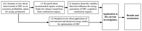
Figure 1.
Flowchart of research methodology.
With this methodology, it was possible to calculate the endogenous and exogenous exergies of the system to find the irreversibilities, as well as to find the destruction of exergy, both avoidable and unavoidable. With these variables, it was possible to observe the technological limit of the system components under study.
2.1. Ssytem Description
For this study, a natural gas ICE with the reference 2 MW Jenbacher JMS 612 GS-N (see Figure 2) was used, in which the intake air and fuel were initially mixed at an atmospheric pressure of about 1.007 bar (7a) at a temperature between 30 and 40 °C and a relative humidity of approximately 80%. Then, the mixture was compressed as it passed through the turbo-compressors (3b), increasing its pressure and temperature. The mixes were later joined at the outlet of the turbo compressors to enter the intake of the combustion chamber where the mixture was first cooled (4a), and then passed through the throttle valve (4b) which took a percentage opening of 80% for island mode and 98% in synchronism, as shown in Table 1. The turbo bypass valve took opening values between 15% to 50% (6a), recirculating the mixture, and regulating the flow supplied to the equipment. After combustion (1b) in a prechamber, exhaust gases were generated (2a) and (2b) at temperatures between 580 and 650 °C. Both exhaust gas flows were mixed (10). It should be noted that the physical parameters of the engine when operating an off-grid mode such as gas temperature and pressure, and likewise, showed the performance indicators in Table 1.
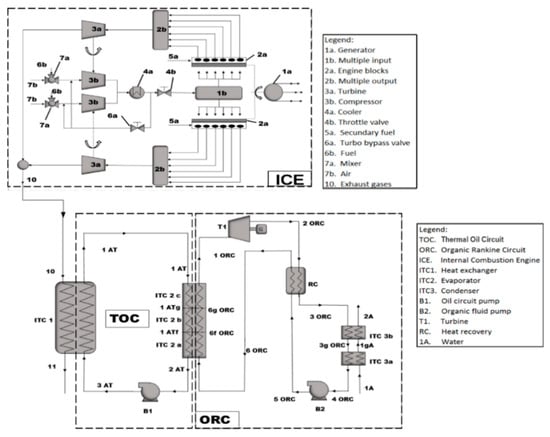
Figure 2.
Physical structure of the waste heat recovery configuration based on recuperative organic Rankine cycle (RORC).

Table 1.
Physical engine parameters and internal combustion engine (ICE) performance indicators.
In the same way, through line (10) (see Figure 2) where the exhaust gases circulate towards the WHR system which the heat exchanger (ITC 1) takes advantage of the waste heat, by which, the heat transferred to the secondary circuit (TOC) which consists of a pump (B1) through which it conducts thermal oil from the line (3 AT) to the line (1 AT) to achieve thermal stability of the organic working fluid and ensures that the RORC working fluid does not exceed its maximum temperature. The heat transfer process between the working fluid and the pentane was performed in the evaporator (ITC 2) which was optimized to minimize both the investment costs of the equipment for the system and the irreversibilities of the heat transfer [48]. This equipment was divided into three zones called preheating (ITC 2c), evaporation (ITC 2b), and overheating (ITC 2a) which serves as a thermal source for the ORC with regenerator where the organic fluid described above as the pentane which when driven by (1 ORC) expands in the turbine (T1) before entering a preheating in the recuperator (RC) where the pressure decreases to enter the condenser which consists of two stages, condensation (ITC 3b) and cooling (ITC 3a). Then, at the pump (B2), the fluid is returned to this recovery unit (RC) at the exchanger evaporation pressures (ITC 2), thus completing the RORC cycle. In Figure 3, a T-s diagram of the RORC system is presented.
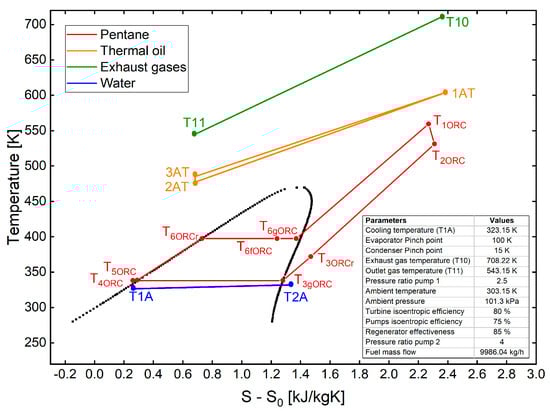
Figure 3.
T-s diagram of the process.
2.2. Energy Analysis
For all components of the ORC, the mass balance of Equation (1) and the energy balance of Equation (2) where applied, where is the mass flow of the working fluid, the specific enthalpy of the working fluid, is the heat transferred, and the work involved. The energy balance of the three-phase heat exchanger is given by Equations (3)–(5). The efficiency and the work generated by the turbine are given by Equations (6) and (7). Equations (8) and (9) show the energy balance for the two-phase condenser (cooling and condensing). The equations that model the thermal process of Pump 2 are described below in Equations (10) and (11). Finally, the energy balance in the regenerator is given in Equation (12).
2.3. Traditional Exergetic Analysis
Exergetic analysis takes into account the second law of thermodynamics, implying that exergetic analysis requires temperature and pressure in the environment where the process under consideration operates. Therefore, the entropy balance for the ORC system with recuperator for the steady state energy process is obtained from Equation (13) [49] as follows:
represents the heat rate in kW, shows the specific entropy for the fluid in kJ/kg·K, is the mass flow in kg/s, a refers to the generation of entropy. With this, the exergy of the thermomechanical flow is defined with Equation (14) as follows:
where and represent enthalpy and entropy in the dead state at temperatures and pressures and ), respectively. Therefore, the exergetic efficiency () for the thermal system is denoted in Equation (15) as a function of output exergy () and the inlet exergy ) for the system or device as follows:
In Table 2, the balance of exergy by component is presented, where the term ) represents the evaporator destroyed exergy, is the turbine destroyed exergy, refers to the pump destroyed exergy, and is the condenser destroyed exergy.
Table 2.
Balance of exergy in components.
For the calculation of the performance indicators for the WHR of an ORC system with a recuperator, the thermal efficiency in the cycle is calculated by Equation (16), the efficiency of the heat recovery represented in Equation (17), the energy conversion efficiency in overall system ) shown in Equation (18) and the absolute increase in thermal efficiency is determined by Equation (19), which relates the energy of the fuel to the net power output of the ORC. This indicator establishes the improvement in the performance of the ICE when an ORC-WHR type recovery system is used and is calculated as follows:
The improvement of the measurement of thermal efficiency, is calculated by improving the thermal efficiency by means of Equation (20) as a function of net work and the mass flow rate . Fuel specific consumption (BSFC) is displayed in Equation (20), and the total specific reduction in fuel consumption as a result of the WHR is shown in Equation (21) as follows:
2.4. Economic Analysis
An economic analysis of a waste heat recovery system from any source by means of an ORC system is based on knowing the total production cost (ETPC), as indicated by Equation (22), is calculated by means of the total capital to be invested (ETCI) and the maintenance and operation costs (EO&M) as follows:
The total capital to be invested in an ORC system is determined by knowing the investment of fixed assets (EFCI) of the system and additional costs. The calculation of the ETCI is made using Equation (23) as follows:
The investment of fixed assets is quantified with the direct costs (EDC) and the indirect costs (EIC), by means of the Equation (24) as follows:
Equation (25) shows the costs that make up the additional costs, where ESUC is the start-up cost, i.e., the commissioning of the equipment, EWC refers to the initial working capital of the system, ELRD is associated with the development and research costs, and finally EAFUDC is the cost attributed to the provision of funds during construction, as follows:
As mentioned before, the investment in fixed assets is made up of direct and indirect costs, where the direct costs represent the acquisition of equipment, piping and accessories, installation and assembly, electronic equipment, instrumentation and control, and the materials corresponding to the system, work area, and civil work. To estimate the cost of equipment acquisition (EPEC), equations proposed by [38,50,51] are used, where correlations are used as a function of the energy of the equipment, specifically, the turbine and pump, and the area in the case of the exchanger; data from manufacturers are collected and costs are calculated in US dollars. From this model, we have Equation (26) for the turbine as follows:
For the pump, is obtained Equation (27) as follows:
Finally, for the heat exchanger, the cost of acquisition is calculated using Equation (28) as follows:
The costs associated with the installation and assembly are related to the transportation and nationalization of the equipment, in addition to the costs generated by the working fluids during the start-up of the thermal cycle, and they are calculated taking, as a reference, between 20% and 90% of the acquisition cost of the equipment [52]. Pipes and accessories are the investments required during the conformation of the project and they are estimated between 50% and 70% of the acquisition cost of the equipment [52]. With respect to instrumentation and control, which is necessary to achieve the most optimal operation of the system, the range is between 6% and 20% of the acquisition cost of the equipment [53]. The electrical equipment and materials are the costs related to the materials and installation of electrical energy distribution lines and the required connections, which also refers to the control centers and equipment to automate the security systems, are estimated between 10% and 15% of the cost of acquisition of equipment [52]. The conditioning of the working environment of the components, refers to the civil work and is calculated to be between 20% and 90% of the acquisition cost of the equipment [52].
The indirect costs are associated with the engineering and supervision, which with a reference between 25% and 75% of the project’s fixed assets, refers to the investment in a work team for the design, administrative expenses, consulting, and inspection of the project’s progress. Construction and contingencies are also part of the indirect costs, both with a maximum reference of 15% of the project’s fixed assets [54].
The additional costs complement the economic analysis of a system and all its configurations, so it is necessary to evaluate the costs of implementation of the system, which is determined by the fixed assets of the capital between 5% and 25%, and are the work required to stabilize the operation of the process. Between 5% and 12% of the project’s fixed assets is the estimate for calculating the working capital. The forecast of funds during construction is calculated with a maximum of 15% of the fixed assets [52,53].
The operation and maintenance of the system are of great importance for the calculation of costs because they are the costs that will occur during the entire operation of the system in its useful life, therefore the investment in supervision is associated with 15% and 30% of the project’s fixed assets to guarantee the life cycle expectation of the system. The supervision guidelines will lead to maintenance orders and this can be associated with a cost between 6% and 10% of the project’s fixed assets [52]. Other operational expenses are endowment, research, and copyrights, which are part of direct miscellaneous costs and are estimated at between 5% and 20% of the project’s fixed assets. Last but not least, due to its high cost, are parafiscal expenses, which are between 30% and 40% of the project’s fixed assets [55].
To obtain level costs, i.e., to bring to an equivalent annuality [52] the capital expenditure for active assets and the maintenance and operating costs, as the former decrease and the latter increase over the years, the constant scaling factor (ECELF) is calculated by means of Equation (29) as follows:
where CRF is the return on capital factor and is calculated by Equation (30), k is the effective annual cost calculated by Equation (31), and n is the life of the project (20 years) [38,56].
where rn is at a nominal scaling rate and is taken with a value of 5% [38,57], and ieff is the annual interest with a value of 5% for the present study [22,58].
2.5. Advanced Exergetic Analysis
It should be noted that the total exergy destruction per component is calculated from the exergy balance as expressed in Equation (32), where ( represents fuel exergy, the exergy produced, and the exergy of loss.
Therefore, for each component, the destruction of exogenous ( is the difference between exergy destroyed ) and is expressed as shown in Equation (33).
Furthermore, exergy destruction values are split up into four parts, i.e., endogenous, exogenous, avoidable, and unavoidable. The destruction of exergy that is avoidable refers to the possibilities of improvement, and unavoidable exergy destruction represents the limit of improvement of the system or device. Equations (34)–(37) are shown below, describing the previous phenomena, where the division of the avoidable and unavoidable exerges into endogenous and exogenous is made, making it possible to find the avoidable endogenous and exogenous parts to find improvement opportunities for the components of the cycle and the inevitable endogenous and exogenous parts to obtain more knowledge about the process.
Therefore, the total destruction of exergy can be written as shown in Equation (38) as follows:
2.6. Fluid Selection
The most commonly used criteria for selecting fluids in ORC systems is the maximum system temperature, although other criteria such as molecular weight, an appropriate relationship between boiling temperature and boiling pressure, and a positive slope in the T-s diagram that characterizes the fluids as dry fluids, are important to ensure that expansion occurs in the reheat region. The cost and toxicity of the fluids is also taken into account as a selection criteria, as well as moderate condensation pressure [59].
For the selection of the fluid, the critical conditions were considered, in which the efficiency of the ORC cycle was increased by using fluids with a critical temperature close to the maximum temperature that the heat source could reach. Thus, organic fluids whose critical temperature (Tcrit) and critical pressure (Pcrit) are above 175 °C, and in a range of 0.2 to 4 MPa, respectively, were considered. Fluids with high boiling points, such as toluene which can reach up to 300 °C, can be applied for heat sources that reach high temperatures. In addition, refrigerants such as R123, HFE700, R227ea, and R245FA, as well as hydrocarbons such as pentanes, butanes, octanes, and hexanes are excellent working fluid options [60].
Although the refrigerants R123, HFE700, R227ea, and R245FA have adequate condensing pressure and critical pressure to meet system criteria, their critical temperature is well below the maximum system temperature. In addition, the refrigerants mentioned show drier behavior than the hydrocarbons in the T-s diagram, which is why pentane, hexane, and octane were the ones chosen to develop the study proposed in this document.
3. Results and Discussions
3.1. Thermodynamic Model Validation
For the present model, the following considerations were taken into account which delimit the scope of the results and govern the phenomenology of the process:
- All the equipment in the cycle are thermally insulated;
- To ensure that the RORC studied works under steady state conditions, it is assumed that the coupling flow in the oil cycle compensates for the temperature changes in the combustion gases;
- Pressure changes in the heat exchangers are considered as a function of the geometry and hydraulic characteristics of the fluid, whereas in the pipes they are not considered as pressure changes.
To validate the RORC model studied in this document, the results of two geothermal applications were taken as reference [38,50]. The parameters of both investigations are shown in Table 3.
Table 3.
System data used for model validation.
A comparison of the results obtained for the model proposed in this research with the referenced results are shown in Table 4. For the three thermodynamic models, there is a good fit of the parameters calculated in this work and those published previously [38,50], and in the case of thermal efficiency an absolute deviation of 0.68% and 0.67%, respectively, was obtained. For the exergetic efficiency, the absolute deviation was 0.27% in both cases, and therefore this model can be used for the evaluation of this configuration operating as a heat recovery system.
Table 4.
Validation of the proposed model for the RORC system.
3.2. Energy and Exergy Analysis of the RORC Configuration
The base condition parameters considered for this investigation in the RORC system are shown in Table 5.
Table 5.
Base condition parameters for a RORC system.
Taking into account the parameters established in Table 5 the thermodynamic properties were obtained for each point of the RORC System duct shown in Table 6.
Table 6.
Thermodynamic properties of the RORC system.
From the simulation results obtained and the thermodynamic properties, some energy and exergy parameters of the WHR system from the engine were calculated, as shown in Table 7. These results show that the WHR system in the base condition result in an increase in thermal efficiency of 1.58% for the natural gas engine, and the RORC has a thermal efficiency of 13.95% and a volumetric energy capacity of 16.28 kJ/m3, which considers the change enthalpy of the system in relation to the density at the exit of the expander.
Table 7.
Performance parameters obtained for the waste heat recovery (WHR) system based on RORC.
The exergy balance was calculated for all the components, as shown in Table 8 which shows the results of traditional exergetic analysis based on the inputs and outputs of the components.
Table 8.
Exergy values for each component.
To perform the heat exchange from the residual steam of the internal combustion engine to the ORC, Therminol 75 is used as a heat exchange fluid, which on its passage through the three-stage heat exchanger transfers heat to the working fluid which changes from the liquid phase to the vapor phase. Previously, the temperature of the working fluid had been increased by means of a regenerator to improve the process in the exchanger. A diagram of the process is shown in Figure 4, where the entire heat gain cycle of the ORC can be observed, starting with the heat gained in the regenerator, and then passing through the three stages of the heat exchanger.
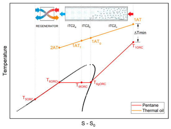
Figure 4.
RORC system heat transfer diagram.
According to the definition of input-output results, the fraction of exergy destroyed in each device was found and is represented in Figure 5. On the one hand, it can be appreciated that greater fractions of exergy are destroyed in the evaporator with a value close to 40.99%, followed by the regenerator with a value of 33.9%, and the condenser with a value of 12.55%. On the other hand, devices that destroy less exergy are the turbine with a value of 7.51%, the exchanger (ITC 1) with a value of 4.56%, and finally Pump 1 and Pump 2 with values of 0.186% and 0.3%, respectively. The components with greater irreversibilities such as the evaporator, regenerator, and condenser are the devices that have greater opportunities for improvement, although the components generate greater amounts of exergy due to interactions with other devices, the nature of the same, or the operating conditions.
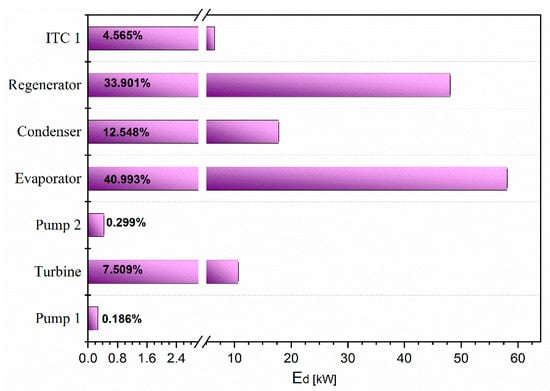
Figure 5.
Exergy destroyed fraction in each RORC system component.
3.3. RORC Thermal Performance: Effect of Pressure Ratio
In this section, the influence of different fluids under different pressure ratios on the behavior of the RORC system have been analyzed. Figure 6 shows that, for all cases, pentane is the fluid which presents the best performance of the system. Otherwise, MD4M and D6 show very similar values that are considerably below the values obtained in the system using the other fluids. Generally, by increasing the pressure ratio, the system performance improves. These results also serve to determine those fluids that could have been chosen for the detailed study in this research and could have obtained similar results to those achieved with the working fluids chosen for the development of the paper.
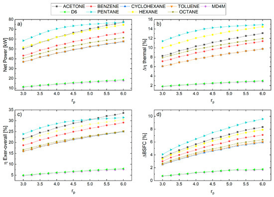
Figure 6.
Performance of the RORC configurations with different working fluids and varying pressure ratios. (a) Net power; (b) Absolute increase in thermal efficiency; (c) Overall exergetic efficiency; and (d) Specific engine fuel consumption-ORC.
The impact of the pressure ratio variability on Pump 2 for pentane, hexane, and octane is comparatively analyzed, due to environmental criteria, thermal stability, safety operation conditions, and lower GWP [61], which made it possible to observe how fluids influence the performance of the RORC system. Taking into account that, for all cases, the fixed values of condensing temperature (Tc) of 65 °C and pinch point of the evaporator (AP) of 100 were maintained, as shown in Figure 7a, as the pressure ratio increases, better net power results are obtained for the pentane, in this case, for the same pressure ratio value of 4, it reaches a net power value of 71.85 kW, followed by Hexane with 62.01 kW, and finally octane with 49.74 kW.
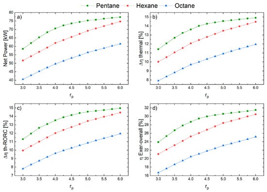
Figure 7.
Performance of different fluids for a RORC system with varying pressure ratios. (a) Net power; (b) Increase in thermal efficiency; (c) RORC thermal efficiency; and (d) Global exergetic efficiency.
Since the main objective is to increase the thermal efficiency of the cycle, it is seen in Figure 7b,c that pentane has the correct behavior for use such as the working fluid in the RORC cycle, since a pressure ratio of 5 has a thermal efficiency in the overall system of 14.55 and a RORC thermal efficiency of 14.96, whereas, for the same pressure ratio condition with hexane, the overall thermal efficiency is 14.47 with a RORC thermal efficiency of 14.46, and for octane a thermal efficiency in the overall system of 11.96 and a RORC thermal efficiency of about 11.95.
Figure 7 shows by the increase of the pressure ratio, that pentane achieves the highest exergetic efficiency, i.e., approximately 32% for a pressure ratio of 6, as compared with hexane and octane. For hexane, an overall exergetic efficiency was achieved that ranged from 21% to 31%, for a pressure ratio variation from 3 to 6, respectively. Similarly, for the case of octane, an overall exergetic efficiency of about 17% to 26% was obtained for a variation of pressure ratio from 3 to 6, respectively, which shows a better performance in exergetic efficiency for hexane than for octane. Therefore, for all the fluids considered, an increase in the variables taken into account in the analysis is shown for a range of pressure ratio from 3 to 6, of which, in all cases, pentane obtained a better performance than the other fluids, which confirms the selection of pentane as a good candidate for the working fluid for this type of system.
3.4. RORC Thermal Performance: Effect of the Condensing Temperature
Now, a comparison of the impact of the change in condensing temperature, Tc, is shown, applied to three fluids, i.e., pentane, hexane, octane, where we can appreciate the influence that temperature variation has on the fluids, and for all cases, the fixed values of pressure ratio were maintained at 6 with an evaporator pinch point of 100, which has been used in the literature [62]. As shown in Figure 8a, at a condensation temperature of about 65 °C a net power of 77.19 kW was obtained with pentane, which resulted, for this condition of operation, in the highest net power among the three fluids. However, as the condensing temperature increased to 71 °C, the net power decreased considerably to 71.24 kW, whereas the net power using hexane increased to 75.31 kW at the temperature previously indicated. Therefore, with an increase in condensing temperature, a slight increase in net power was achieved using hexane, and a reduction in power using pentane. For octane, a net power of about 62 kW was maintained.
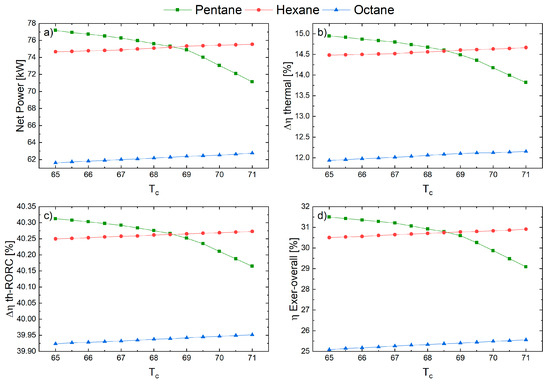
Figure 8.
Performance of different fluids for a RORC system with varying condensing temperature. (a) Net power; (b) Increase in thermal efficiency; (c) RORC thermal efficiency; and (d) Global exergetic efficiency.
Similarly, for an increase in condensing temperature, as shown from Figure 8b,d, when the condensing temperature is below 68 °C, pentane behaves correctly as a working fluid. However, when the condensing temperature is above 69 °C, the pressure ratio equals 6 and the pinch point of the evaporator reaches 100 °C, and hexane achieves overall thermal efficiency, ORC thermal efficiency, and overall exergetic efficiency superior to pentane. Thus, for these particular cases, it can be stated that there is no organic working fluid that can guarantee the best performance in all system operating ranges. In addition, a condensing temperature range from 65 to 68.6 °C implies the best overall exergetic efficiency from approximately 31.5% to 30.6% for pentane, followed by hexane with values from 30.5% to 30.7%, as shown in Figure 8d. Then, octane presented the lowest overall exergetic efficiency values ranging from 25.2% to 25.4%. Therefore, hexane and pentane differ, in that a good behavior of the variables of interest is observed for an increase in the condensing temperature, except for pentane, which shows decreasing behavior in the range between 65 °C and 71 °C. However, it was analyzed that at condensing temperatures below 68 °C, pentane shows more desirable results on the system, which is a consequence of the irreversibilities presented in the heat exchanger and turbine, as was concluded by Valencia et al. [38].
Figure 9d shows the variability of the pinch point of the evaporator for pentane, hexane, and octane. As shown in Figure 9, at a pinch point of 92 °C, and keeping the conditions of condensing temperature at 65 °C and pressure ratio of 6 constant, the best performance was presented by pentane (82.45 kW), followed by hexane (79.96 kW), and octane (62.87 kW), respectively. Figure 9b,c shows that as the evaporator pinch point increases, the absolute increase in thermal efficiency and ORC thermal efficiency decreases [61], which is caused by increased heat transfer irreversibilities in the evaporator, besides a decrease in the difference in enthalpies of the fluid at the moment of expansion in the turbine, and consequently, a decrease in the generated power; results that have been confirmed by Valencia et al. [62]. In addition, Figure 9d shows that the evaporator pinch point with pentane at 92 °C, obtains an overall exergetic efficiency of 33.69%, indicating that when the pinch point is increased to 98 °C, it continues to maintain an exergetic efficiency higher than hexane and octane.
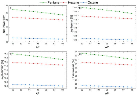
Figure 9.
Performance of different fluids for a RORC system with varying AP. (a) Net power; (b) Absolute increase in thermal efficiency; (c) RORC thermal efficiency; and (d) Global exergetic efficiency.
Therefore, regarding the plots presented in Figure 9, it is inferred that by increasing the pinch point and using pentane, increases in net power, thermal efficiency, ORC thermal efficiency, and in overall exergetic efficiency are obtained as compared with using hexane and octane organic fluids. With this, greater efficiency is achieved in the system using pentane, and for the proposed conditions, it is concluded that it provides a suitable performance for use as a working fluid in the RORC cycle. In conclusion, the results obtained show that for the three selected fluids a decreasing trend along the pinch point range between 92 °C and 98 °C related to the variables that describe the performance of the system, where pentane has an fascinating outcome that needs to be studied from a thermoeconomic point of view for the organic Rankine cycle system.
3.5. RORC Thermal Performance: Effect of the Evaporator Pinch Point Effect
This unit considers the influence of engine load on the performance of the heat recovery system based on a RORC cycle. The results presented above that correspond to a sensitivity analysis were obtained based on the most representative operating condition of the gas engine. Internal engine variables such as pressure, mixture temperature, and mixture recirculation percentage are controlled by the engine power control system to provide high efficiency in partial load engine operations. Global energy indicators with an equal evaporating pressure configuration for the three fluids under study of 675.8 kPa were chosen as study variables, as shown in Figure 10. To avoid liquid corrosion in the expander, for safety reasons, all feasible operating points of the proposed configurations of the different engine loads ensure that the working fluids at the evaporator outlet evaporate completely, in addition to a gas temperature at the evaporator outlet, i.e., current 11, higher than the acid dew temperature (200 °C) to prevent acid corrosion of the exhaust.
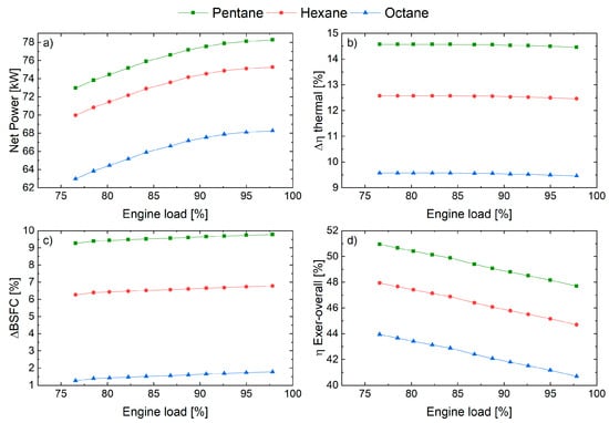
Figure 10.
Performance of RORC configurations with different engine loads. (a) Net power; (b) Absolute increase in thermal efficiency; (c) Specific engine fuel consumption-ORC; (d) Overall exergetic efficiency.
As well as the absolute thermal efficiency increases, the overall energy conversion efficiency decreases with increasing engine load. The maximum net output power achieved for RORC configurations with respect to engine load percentages is 78.28 Kw and 97.8% for pentane, 75.52 kW and 97.8% for hexane, and 86.29 kW and 68.82% for octane. However, over a period of motor operation, the thermal efficiency increase, for the RORC configuration, first increases, and then decreases, achieving a maximum of 78.5% motor load.
These results correspond to the fact that, at a higher engine load, a greater flow of exhaust gases is achieved, which increases the energy loss in the recuperator, due to the limited evaporation pressure and temperatures of the thermal coupling oil. As the operating load increases, there is an increase in the fluid evaporation temperature in the ITC 2. Consequently, the power increases, which is the primary element for increasing thermal and exergetic efficiency. However, the isentropic efficiency of the turbine decreases slightly due to the increase in thermal oil temperature, causing a decrease in the indicators at high engine loads. This trend of increasing power at engine load is a result of both the increase in thermal oil inlet temperature to the evaporator, which causes an increase in the working fluid mass flow, and the difference in enthalpy between the pump and turbine inlet and outlet of the system, but the latter is more clearly seen in the turbine.
3.6. Economic Evaluation
Table 9 shows the results of the economic evaluation carried out by the WHR system using ORC. To obtain the results, the purchased equipment cost (PEC) and the fixed capital investment (FCI) were obtained, which are fundamental for the calculation of the other costs by means of percentages of the PEC and the FCI. The results of the total production cost (TPC) of the WHR system using ORC show that when pentane is used as the working fluid the costs are higher with a value of 9606.56 USD/kW, following, in descending order, when hexane is used the total production cost is 9419.97 USD/kW, and finally when octane is used a total production cost equal to 9297.20 USD/kW, which indicates that the more efficient the system is the more expensive it is, and on the contrary, when the configuration is less efficient the associated costs decrease.
Table 9.
Total production costs estimation for different working fluid.
The results show that there is a direct relationship between the total cost of the equipment and the thermal and exergetic efficiency obtained. Thus, the system operating with pentane with a higher cost, at a pressure ratio of 6 presents an absolute increase of thermal efficiency of 14.96%, followed by the system operating with hexane (14.46%), and finally with octane (11.95%). Therefore, in these systems, efficiency and equipment size are related, since an increase in size affects equipment acquisition costs.
In the same way, direct costs are mostly represented by equipment acquisition costs, which were determined by equations available in the literature for each of the equipment as a function of its energy in kW, as is the case of the turbine and pump, and as a function of the exchanger area in m2, which collect data from manufacturers and calculate costs in U.S. dollars [38,50,51]. Thus, power density in kW/m2 has been considered to be a performance indicator of the ORC, considering the heat exchange area of the ITC 1, ITC 2, and ITC 3. Thus, pentane, with a total heat transfer area of 62.04 m2, presented a pressure ratio of 6 and the best values of this performance indicator (1.25 kW/m2), followed by hexane (1.11 kW/m2), and finally octane with a power of 61.47 kW and an indicator of 0.89 kW/m2. Therefore, once again it is confirmed that this fluid is preferred for this system.
3.7. Advanced Exergetic Analysis
In this way, an advanced exergetic analysis is proposed, finding the endogenous destroyed exergy that arises from the interception of the inclined line with the [65], taking into account that this interception must be greater than zero and less than the for each device. In Figure 11, the graphical method for obtaining the value of endogenous exergy destruction is shown for Pump 1, Pump 2, the condenser, the evaporator, the regenerator, and the turbine, where a four-point regression was performed between the exergy destruction between the exergy destruction of the cycle without the component to be studied (Ed others) and the total exergy destruction of the system (Efuel-Eproduct-Eloss), having the exergetic efficiency of the component as a fixed value and starting point in the graph [66]. By regressing to the point where the line is intercepted with the values of total exergy destroyed from the system, the endogenous exergy destruction values of each component can be found as follows: Pump 1 (Figure 11a) 0.11 kW, Pump 2 (Figure 11b) 0.27 kW, the condenser (Figure 11c) 4.01 kW, the evaporator (Figure 11d) 40.44 kW, the regenerator (Figure 11e) 38.92 kW, and the turbine 1.61 kW. It is observed that the evaporator and the regenerator have the highest values of endogenous exergy destroyed due to the fact that they are heat exchangers, it is possible that they are working inefficiently, and therefore it is necessary to take into account these components to make technical and economic improvements through advanced and exergo-economic analysis to find technical and economic improvements.
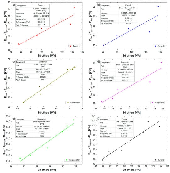
Figure 11.
Exergy destroyed endogenously for (a) Pump 1; (b) Pump 2; (c) Condenser; (d) Evaporator; (e) Regenerator; and (f) Turbine.
Taking into account that some operating conditions are chosen for the unavoidable exergy, the selection of the parameters is given by the studies mentioned in Table 10.
Table 10.
Unavoidable operation condition for each component [8,42].
Taking into account the conditions in Table 10, together with the equations, which are found in the contents of Section 2.4, the division of the exergy destroyed into avoidable and unavoidable can be carried out, annexing this to the endogenous and exogenous part, obtaining avoidable and unavoidable parts of the endogenous and exogenous parts for each component for each of the components except for the condenser and regenerator, because they operate as a heat sink. Figure 12 shows that the percentage of the different divisions of the exergy destroyed found so far for each component, showing emphasis on the opportunities for both endogenous and exogenous improvements.
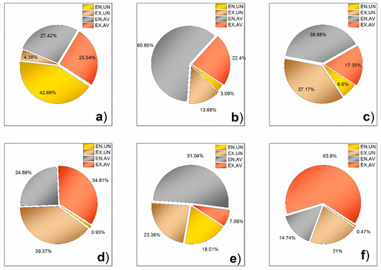
Figure 12.
Disaggregation of the exercise into the avoidable and inevitable endogenous portion and the avoidable and inevitable exogenous component part for (a) Pump 1; (b) Pump 2; (c) Evaporator; (d) Heat exchanger 1 (ITC 1); (e) Regenerator; and (f) Turbine.
According to Figure 12, the improvement opportunities differ for the Pump 2 component, i.e., 60.85% of endogenous character and 22.4% of exogenous character can be avoided. In addition, for the evaporator, 38.88% of endogenous character and 17.35% of exogenous character can be avoided. Likewise, the improvement opportunities for the turbine are more significant if it is of an exogenous nature with 63.8%, which means that the improvement opportunities depend on the components with which it interacts. Table 10 shows the values of exogenous exergy destroyed, which are similar to a study by Galindo et al. [36]. Their results in the ORC cycle, indicated that the greatest potential for improvement through technical modifications was in the turbine where 88% of the exergy destroyed in this way could be reduced by improving technology of the avoidable/endogenous component [44,45,67], whereas, in the pump, it could be reduced by 70% by means of operational optimization [68]. Similarly, in this study, a greater opportunity for improvement was observed in an endogenous way (60.85%) in Pump 2 where the organic fluid is transported, therefore the studies on the performance of organic fluids in these systems should be continued [47,48]. However, in the case of the turbine, a very large fraction (63.8%) can be seen to be exogenously and avoidably improved by other devices, which is also presented in others research result [69], implying a device whit a relevant environmental impact [70].
The values in Table 11 indicate the total exogenous energy destruction of the system, which is higher with 64.15% as compared with exogenous (35.85%), and indicate that the exogenous energy destruction shows when all the system components interact. The reduction of the exergy destroyed from these components takes more advantage of the energy potential of energy recovery systems [71], which is available in several power generation systems, such as natural gas generation engines [72], reciprocating internal combustion diesel engines [73], and gas turbines operating in trigeneration systems [74]. In addition, the component with the most significant opportunity for improvement is the evaporator (19.14 kW) and the turbine (8.35 kW). For ITC 1 and the evaporator, negative exogenous values are presented, related to the inconsistency of the flows in the component and the real and inevitable temperature conditions in the case study.
Table 11.
Disaggregation of exergy for system components.
4. Conclusions
The total exergy destruction of each component in a system can be divided into endogenous and exogenous, and each can be avoidable and unavoidable, to determine, besides the avoidable part due to the destruction of exergy identified by the traditional exergy analysis, which part is due to the structure or the operating conditions for the component in question. Therefore, many opportunities for improvement focus on the avoidable endogenous/exogenous fraction, where it is considered whether the improvement of the system depends on the device itself or on the interaction with the other components of the WHR system using ORC.
The traditional exergy analysis of an ORC-based waste WHR system was performed using working fluids such as pentane, hexane, and octane, and the thermal inefficiencies of the primary devices were observed. However, it was not possible to determine the proportion of inefficiencies, how they could be avoided, or to study how they affected the interactions among each of the components that composed the system using only traditional exergy analysis.
In most components, the exergy destroyed was usually produced by the nature of the component itself, however, there were also opposite cases such as the case of Pump 2 and the evaporator where, in percentage terms, the exogenous exergy destroyed was 36.06% and 54.52%, most of it being unavoidable. Thus, the interaction between components also plays an important role in some components, that is, an improvement in the others will positively affect components such as Pump 2 and the evaporator, which translates into a lower exergy destroyed.
On the basis of the operating conditions of the WHR systems on ORC-based, the results showed that pentane was the working fluid with the best results, with 28% of net power higher than octane. For the condensing temperature using octane, there was no significant influence on the net power. However, for pentane, a decrease in net power was observed as the condensing temperature increased, and the opposite behavior was presented with hexane. In addition, the pinch point temperature of the evaporator rise implied a decrease in the thermal efficiency, with was a consequence of the higher irreversibilities presented in the evaporator heat exchanger. However, it was shown that the effect is less accentuated in the case of pentane, which maintained an exergetic overall efficiency above 32%, with an evaporator pinch point ranging from 92 to 98 °C.
In addition, the effect of increased thermal efficiency, evaporation pressure on net energy production, overall energy conversion efficiency, and specific fuel consumption and exergy destruction were also investigated. The results showed that the best configuration is that of RORC with toluene as the working fluid, because it improves operational performance by achieving an overall conversion efficiency of 11.58%, a net power of 146.25 kW, a reduction in fuel consumption of 7.67% and an ORC thermal efficiency of 28.4% at an engine speed of 1482 rpm, 1.78 lambda, a natural gas flow of 120.2 L/min, and 1758.77 kW of mechanical engine power. However, to contribute in the industrial adoption of this technology, it is necessary to conduct energy, exergy, and thermoeconomic optimization to obtain performance indicators of the waste heat recovery system, and viable thermal solutions to increase the thermal efficiency of this type of natural gas engine.
The exergetic analysis showed that the condenser had the highest percentage of exergy destroyed with 40.99%, while the lowest was obtained in Pump 1 with a value of 0.19%. The components with greater irreversibilities such as the evaporator, regenerator, and condenser were the devices that allow, according to the proposed analysis methodology, for the improvement of the system under consideration, since they concentrated 85% of the destroyed exergy and had greater opportunities for improvement. Due to this, the conditions were analyzed where the endogenous destroyed exergy was greater than zero and less than the for each device. The advantages of performing an advanced exergetic analysis for each component was that we established that the most significant opportunities for improvement occurred in the turbine with 63.8% of exogenous character and in the evaporator with 38.88% of endogenous character and 17.35% of exogenous character. For future study, it is recommended to apply an optimization of the heat transfer mechanisms on the components to minimize the exergy destroyed, since this could represent a limitation if a more realistic model was desired, which could be complemented with a computational fluid dynamic (CFD) analysis of some components such as the turbines.
Author Contributions
Conceptualization, J.C.G.; Methodology, J.C.G., G.V.O., and J.D.-F.; Software, J.C.G., J.D.-F., and G.V.O.; Validation, J.C.G., J.D.-F., and G.V.O.; Formal analysis, J.C.G., J.D.-F., and G.V.O.; Investigation, J.C.G., J.D.-F., and G.V.O.; Resources, J.C.G.; Writing—Original Draft Preparation, G.V.O.; Writing—Review & Editing, J.C.G. and J.D.-F.; Funding acquisition, J.C.G. and G.V.O. All authors have read and agreed to the published version of the manuscript.
Funding
This research was supported by the Universidad Francisco de Paula Santander and the Universidad del Atlántico, located in Bucaramanga and Barranquilla, Colombia, respectively.
Acknowledgments
This research was supported by the Mechanical Engineering Program of Universidad del Atlántico and the Universidad Francisco de Paula Santander.
Conflicts of Interest
The authors consider there is no conflict of interest.
Abbreviations
The following abbreviations are used in this manuscript:
| CRF | Return on capital factor |
| FCI | Investment of fixed assets |
| ICE | Internal combustion engine |
| ITC 1 | Heat exchanger 1 |
| ITC 2 | Evaporator |
| ITC 3 | Condenser |
| ORC | Organic Rankine cycle |
| RC | Heat recovery |
| TCI | Total capital to be invested |
| TOC | Thermal oil circuit |
| TPC | Total production cost |
Nomenclature
| EAFUDC | Cost attributed to the provision of funds |
| ECELF | Constant scaling factor |
| Direct costs | |
| Exergy destruction (kW) | |
| Endogenous exergy destruction kW) | |
| Exogenous exergy destruction (kW) | |
| Indirect costs | |
| ELRD | Development and research costs |
| ESUC | Start-up cost |
| EWC | Initial working capital of the system |
| ieff | Annual interest |
| k | Effective annual cost |
| Mass flow rate | |
| n | Life of the project |
| Heat power | |
| rn | Nominal scaling rate |
| Heat recovery efficiency | |
| Temperature | |
| Time | |
| Net power (kW) | |
| Molar gas fraction | |
| Thermal efficiency of the cycle | |
| Overall energy conversion efficiency | |
| Exergetic efficiency | |
| Heat recovery efficiency | |
| Destroyed | |
| G | Gases |
| o | Reference condition |
| Subscript | |
| F | Fuel |
| P | Product |
| Superscripts | |
| AV | Avoidable |
| EN | Endogenous |
| EX | Exogenous |
| EN, AV | Endogenous avoidable |
| EN, UN | Endogenous unavoidable |
| UN | Unavoidable |
References
- Valencia, G.; Benavides, A.; Cardenas Escorcia, Y. Economic and Environmental Multiobjective Optimization of a Wind–Solar–Fuel Cell Hybrid Energy System in the Colombian Caribbean Region. Energies 2019, 12, 2119. [Google Scholar] [CrossRef]
- Lecompte, S.; Huisseune, H.; Van Den Broek, M.; Vanslambrouck, B.; De Paepe, M. Review of organic Rankine cycle (ORC) architectures for waste heat recovery. Renew. Sustain. Energy Rev. 2015, 47, 448–461. [Google Scholar] [CrossRef]
- Quoilin, S.; Van Den Broek, M.; Declaye, S.; Dewallef, P.; Lemort, V. Techno-economic survey of organic rankine cycle (ORC) systems. Renew. Sustain. Energy Rev. 2013, 22, 168–186. [Google Scholar] [CrossRef]
- Rahbar, K.; Mahmoud, S.; Al-Dadah, R.K.; Moazami, N.; Mirhadizadeh, S.A. Review of organic Rankine cycle for small-scale applications. Energy Convers. Manag. 2017, 134, 135–155. [Google Scholar] [CrossRef]
- Lecompte, S.; Oyewunmi, O.; Markides, C.; Lazova, M.; Kaya, A.; den Broek, M.; De Paepe, M. Case Study of an Organic Rankine Cycle (ORC) for Waste Heat Recovery from an Electric Arc Furnace (EAF). Energies 2017, 10, 649. [Google Scholar] [CrossRef]
- Nazir, C.P. Solar Energy for Traction of High Speed Rail Transportation: A Techno-economic Analysis. Civ. Eng. J. 2019, 5, 1566–1576. [Google Scholar] [CrossRef]
- Hysa, A. Modeling and Simulation of the Photovoltaic Cells for Different Values of Physical and Environmental Parameters. Emerg. Sci. J. 2019, 3, 395–406. [Google Scholar] [CrossRef]
- Piero Rojas, J.; Valencia Ochoa, G.; Duarte Forero, J. Comparative Performance of a Hybrid Renewable Energy Generation System with Dynamic Load Demand. Appl. Sci. 2020, 10, 3093. [Google Scholar] [CrossRef]
- Landelle, A.; Tauveron, N.; Haberschill, P.; Revellin, R.; Colasson, S. Organic Rankine cycle design and performance comparison based on experimental database. Appl. Energy 2017, 204, 1172–1187. [Google Scholar] [CrossRef]
- Song, P.; Wei, M.; Shi, L.; Danish, S.N.; Ma, C. A review of scroll expanders for organic rankine cycle systems. Appl. Therm. Eng. 2015, 75, 54–64. [Google Scholar] [CrossRef]
- Su, W.; Zhao, L.; Deng, S. Simultaneous working fluids design and cycle optimization for Organic Rankine cycle using group contribution model. Appl. Energy 2017, 202, 618–627. [Google Scholar] [CrossRef]
- Wang, E.H.; Zhang, H.G.; Fan, B.Y.; Ouyang, M.G.; Zhao, Y.; Mu, Q.H. Study of working fluid selection of organic Rankine cycle (ORC) for engine waste heat recovery. Energy 2011, 36, 3406–3418. [Google Scholar] [CrossRef]
- Polytechnic, K. 98/01752 A review of organic Rankine cycles (ORCs) for the recovery of low-grade waste heat. Fuel Energy Abstr. 1998, 39, 151. [Google Scholar]
- Hermann, W.A. Quantifying global exergy resources. Energy 2006, 31, 1685–1702. [Google Scholar] [CrossRef]
- Hung, T.C.; Wang, S.K.; Kuo, C.H.; Pei, B.S.; Tsai, K.F. A study of organic working fluids on system efficiency of an ORC using low-grade energy sources. Energy 2010, 35, 1403–1411. [Google Scholar] [CrossRef]
- Rayegan, R.; Tao, Y.X. A procedure to select working fluids for Solar Organic Rankine Cycles (ORCs). Renew. Energy 2011, 36, 659–670. [Google Scholar] [CrossRef]
- Colonna, P.; Casati, E.; Trapp, C.; Mathijssen, T.; Larjola, J.; Turunen-Saaresti, T.; Uusitalo, A. Organic Rankine Cycle Power Systems: From the Concept to Current Technology, Applications, and an Outlook to the Future. J. Eng. Gas. Turbines Power 2015, 137, 1–19. [Google Scholar] [CrossRef]
- Hou, Z.; Wei, X.; Ma, X.; Meng, X. Exergoeconomic evaluation of waste heat power generation project employing organic Rankine cycle. J. Clean. Prod. 2020, 246, 119064. [Google Scholar] [CrossRef]
- Arabkoohsar, A. Combined steam based high-temperature heat and power storage with an Organic Rankine Cycle, an efficient mechanical electricity storage technology. J. Clean. Prod. 2020, 247, 119098. [Google Scholar] [CrossRef]
- Kosuda, O.; Hikichi, T.; Kido, O.; Nishiyama, N. Development of air-cooled compact Organic Rankine Cycle power generation technology utilizing waste heat. Energy Procedia 2017, 129, 559–566. [Google Scholar] [CrossRef]
- Ziviani, D.; Beyene, A.; Venturini, M. Advances and challenges in ORC systems modeling for low grade thermal energy recovery. Appl. Energy 2014, 121, 79–95. [Google Scholar] [CrossRef]
- Tchanche, B.; Lambrinos, G.; Frangoudakis, A.; Papadakis, G. Low-grade heat conversion into power using organic Rankine cycles-A review of various applications. Renew. Sustain. Energy Rev. 2011, 15, 3963–3979. [Google Scholar] [CrossRef]
- Liu, B.T.; Chien, K.H.; Wang, C.C. Effect of working fluids on organic Rankine cycle for waste heat recovery. Energy 2004, 29, 1207–1217. [Google Scholar] [CrossRef]
- Quoilin, S.; Declaye, S.; Tchanche, B.F.; Lemort, V. Thermo-economic optimization of waste heat recovery Organic Rankine Cycles. Appl. Therm. Eng. 2011, 31, 2885–2893. [Google Scholar] [CrossRef]
- Badr, O.; O’Callaghan, P.W.; Probert, S.D. Rankine-cycle systems for harnessing power from low-grade energy sources. Appl. Energy 1990, 36, 263–292. [Google Scholar] [CrossRef]
- Shu, G.; Li, X.; Tian, H.; Liang, X.; Wei, H.; Wang, X. Alkanes as working fluids for high-temperature exhaust heat recovery of diesel engine using organic Rankine cycle. Appl. Energy 2014, 119, 204–217. [Google Scholar] [CrossRef]
- UNEP (United Nations Environmental Programme). Montreal Protocol on Substances That Deplete the Ozone Layer: Technology and Economic Assessment Panel; UNEP: Nairobi, Kenya, 1997. [Google Scholar]
- United Nations Framework Convention on Climate Change. Kyoto Protocol to the United Nations Framework Convention on Climate Change. 1998. Available online: http://unfccc.int/resource/docs/convkp/kpeng.pdf (accessed on 28 November 2019).
- Xu, R.J.; He, Y.L. A vapor injector-based novel regenerative organic Rankine cycle. Appl. Therm. Eng. 2011, 31, 1238–1243. [Google Scholar] [CrossRef]
- Nguyen, T.; Johnson, P.; Akbarzadeh, A.; Gibson, K.; Mochizuki, M. Design, manufacture and testing of a closed cycle thermosyphon rankine engine. Heat Recover. Syst. CHP 1995, 15, 333–346. [Google Scholar] [CrossRef]
- Sprouse, C.; Depcik, C. Review of organic Rankine cycles for internal combustion engine exhaust waste heat recovery. Appl. Therm. Eng. 2013, 51, 711–722. [Google Scholar] [CrossRef]
- Toffolo, A.; Lazzaretto, A.; Manente, G.; Paci, M. A multi-criteria approach for the optimal selection of working fluid and design parameters in Organic Rankine Cycle systems. Appl. Energy 2014, 121, 219–232. [Google Scholar] [CrossRef]
- Desai, N.B.; Bandyopadhyay, S. Thermo-economic analysis and selection of working fluid for solar organic Rankine cycle. Appl. Therm. Eng. 2016, 95, 471–481. [Google Scholar] [CrossRef]
- Imran, M.; Park, B.S.; Kim, H.J.; Lee, D.H.; Usman, M.; Heo, M. Thermo-economic optimization of Regenerative Organic Rankine Cycle for waste heat recovery applications. Energy Convers. Manag. 2014, 87, 107–118. [Google Scholar] [CrossRef]
- Mohammadi, Z.; Fallah, M.; Mahmoudi, S.M.S. Advanced exergy analysis of recompression supercritical CO2 cycle. Energy 2019, 178, 631–643. [Google Scholar] [CrossRef]
- Galindo, J.; Ruiz, S.; Dolz, V.; Royo-Pascual, L. Advanced exergy analysis for a bottoming organic rankine cycle coupled to an internal combustion engine. Energy Convers. Manag. 2016, 126, 217–227. [Google Scholar] [CrossRef]
- Nami, H.; Nemati, A.; Jabbari Fard, F. Conventional and advanced exergy analyses of a geothermal driven dual fluid organic Rankine cycle (ORC). Appl. Therm. Eng. 2017, 122, 59–70. [Google Scholar] [CrossRef]
- El-Emam, R.S.; Dincer, I. Exergy and exergoeconomic analyses and optimization of geothermal organic Rankine cycle. Appl. Therm. Eng. 2013, 59, 435–444. [Google Scholar] [CrossRef]
- Khaljani, M.; Khoshbakhti Saray, R.; Bahlouli, K. Comprehensive analysis of energy, exergy and exergo-economic of cogeneration of heat and power in a combined gas turbine and organic Rankine cycle. Energy Convers. Manag. 2015, 97, 154–165. [Google Scholar] [CrossRef]
- Safarian, S.; Aramoun, F. Energy and exergy assessments of modified Organic Rankine Cycles (ORCs). Energy Reports 2015, 1, 1–7. [Google Scholar] [CrossRef]
- Li, J.; Pei, G.; Li, Y.; Wang, D.; Ji, J. Energetic and exergetic investigation of an organic Rankine cycle at different heat source temperatures. Energy 2012, 38, 85–95. [Google Scholar] [CrossRef]
- König-Haagen, A.; Höhlein, S.; Brüggemann, D. Detailed exergetic analysis of a packed bed thermal energy storage unit in combination with an Organic Rankine Cycle. Appl. Therm. Eng. 2019, 114583. [Google Scholar] [CrossRef]
- Jannatkhah, J.; Najafi, B.; Ghaebi, H. Energy and exergy analysis of combined ORC—ERC system for biodiesel-fed diesel engine waste heat recovery. Energy Convers. Manag. 2020, 209, 112658. [Google Scholar] [CrossRef]
- Song, J.; Gu, C. Parametric analysis of a dual loop Organic Rankine Cycle (ORC) system for engine waste heat recovery. Energy Convers. Manag. 2015, 105, 995–1005. [Google Scholar] [CrossRef]
- Song, J.; Song, Y.; Gu, C. Thermodynamic analysis and performance optimization of an Organic Rankine Cycle (ORC) waste heat recovery system for marine diesel engines. Energy 2015, 82, 976–985. [Google Scholar] [CrossRef]
- Neto, R.d.O.; Sotomonte, C.A.R.; Coronado, C.J.R.; Nascimento, M.A.R. Technical and economic analyses of waste heat energy recovery from internal combustion engines by the Organic Rankine Cycle. Energy Convers. Manag. 2016, 129, 168–179. [Google Scholar] [CrossRef]
- Galindo, J.; Ruiz, S.; Dolz, V.; Royo-Pascual, L.; Haller, R.; Nicolas, B.; Glavatskaya, Y. Experimental and thermodynamic analysis of a bottoming Organic Rankine Cycle (ORC) of gasoline engine using swash-plate expander. Energy Convers. Manag. 2015, 103, 519–532. [Google Scholar] [CrossRef]
- Valencia, G.; Núñez, J.; Duarte, J. Multiobjective optimization of a plate heat exchanger in a waste heat recovery organic rankine cycle system for natural gas engines. Entropy 2019, 21, 665. [Google Scholar] [CrossRef]
- Tchanche, B.F.; Lambrinos, G.; Frangoudakis, A.; Papadakis, G. Exergy analysis of micro-organic Rankine power cycles for a small scale solar driven reverse osmosis desalination system. Appl. Energy 2010, 87, 1295–1306. [Google Scholar] [CrossRef]
- Zare, V. A comparative exergoeconomic analysis of different ORC configurations for binary geothermal power plants. Energy Convers. Manag. 2015, 105, 127–138. [Google Scholar] [CrossRef]
- Calise, F.; Capuozzo, C.; Carotenuto, A.; Vanoli, L. Thermoeconomic analysis and off-design performance of an organic Rankine cycle powered by medium-temperature heat sources. Sol. Energy 2014, 103, 595–609. [Google Scholar] [CrossRef]
- Bejan, A.; Tsatsaronis, G.; Moran, M.J. Thermal Design and Optimization; John Wiley & Sons Inc.: Hoboken, NJ, USA, 1995; ISBN 0471584673/9780471584674. [Google Scholar]
- Ochoa, G.V.; Isaza-Roldan, C.; Duarte Forero, J. Economic and Exergo-Advance Analysis of a Waste Heat Recovery System Based on Regenerative Organic Rankine Cycle under Organic Fluids with Low Global Warming Potential. Energies 2020, 13, 1317. [Google Scholar] [CrossRef]
- Voros, N.G.; Kiranoudis, C.T.; Maroulis, Z.B. Solar energy exploitation for reverse osmosis desalination plants. Desalination 1998, 115, 83–101. [Google Scholar] [CrossRef]
- Kotas, T.J. The Exergy Method of Thermal Plant. Analysis; Butterwort; Elsevier: Amsterdam, The Netherlands, 1985; ISBN 978-0-408-01350-5. [Google Scholar]
- Preißinger, M.; Brüggemann, D. Thermoeconomic Evaluation of Modular Organic Rankine Cycles for Waste Heat Recovery over a Broad Range of Heat Source Temperatures and Capacities. Energies 2017, 10, 269. [Google Scholar] [CrossRef]
- Baral, S.; Kim, D.; Yun, E.; Kim, K. Experimental and Thermoeconomic Analysis of Small-Scale Solar Organic Rankine Cycle (SORC) System. Entropy 2015, 17, 2039–2061. [Google Scholar] [CrossRef]
- Han, Z.; Li, P.; Han, X.; Mei, Z.; Wang, Z. Thermo-Economic Performance Analysis of a Regenerative Superheating Organic Rankine Cycle for Waste Heat Recovery. Energies 2017, 10, 1593. [Google Scholar] [CrossRef]
- Nafey, A.S.; Sharaf, M.A. Combined solar organic Rankine cycle with reverse osmosis desalination process: Energy, exergy, and cost evaluations. Renew. Energy 2010, 35, 2571–2580. [Google Scholar] [CrossRef]
- Schuster, A.; Karellas, S.; Kakaras, E.; Spliethoff, H. Energetic and economic investigation of Organic Rankine Cycle applications. Appl. Therm. Eng. 2009, 29, 1809–1817. [Google Scholar] [CrossRef]
- Ochoa, G.V.; Peñaloza, C.A.; Rojas, J.P. Thermoeconomic modelling and parametric study of a simple orc for the recovery ofwaste heat in a 2 MW gas engine under differentworking fluids. Appl. Sci. 2019, 9, 4526. [Google Scholar] [CrossRef]
- Valencia, G.; Fontalvo, A.; Cardenas Escorcia, Y.; Duarte, J.; Isaza-Roldan, C. Energy and Exergy Analysis of Different Exhaust Waste Heat Recovery Systems for Natural Gas Engine Based on ORC. Energies 2019, 12, 2378. [Google Scholar] [CrossRef]
- Sinnott, R.K.; Towler, G. Chemical Engineering Design, 2nd ed.; Butterworth-Heinemann: Oxford, UK, 2013; ISBN 9780080966595. [Google Scholar]
- Peters, M.S.; Timmerhaus, K.D. Plant Design and Economics for Chemical Engineers, 4th ed.; Timmerhaus: New York, NY, USA, 1991; ISBN 0-07-049613-7. [Google Scholar]
- Boyaghchi, F.A.; Molaie, H. Investigating the effect of duct burner fuel mass flow rate on exergy destruction of a real combined cycle power plant components based on advanced exergy analysis. Energy Convers. Manag. 2015, 103, 827–835. [Google Scholar] [CrossRef]
- Petrakopoulou, F.; Tsatsaronis, G.; Morosuk, T.; Carassai, A. Conventional and advanced exergetic analyses applied to a combined cycle power plant. Energy 2012, 41, 146–152. [Google Scholar] [CrossRef]
- Peris, B.; Navarro-Esbrí, J.; Molés, F. Bottoming organic Rankine cycle configurations to increase Internal Combustion Engines power output from cooling water waste heat recovery. Appl. Therm. Eng. 2013, 61, 364–371. [Google Scholar] [CrossRef]
- Valencia Ochoa, G.; Acevedo Peñaloza, C.; Duarte Forero, J. Thermoeconomic Optimization with PSO Algorithm of Waste Heat Recovery Systems Based on Organic Rankine Cycle System for a Natural Gas Engine. Energies 2019, 12, 4165. [Google Scholar] [CrossRef]
- Valencia Ochoa, G.; Piero Rojas, J.; Duarte Forero, J. Advance Exergo-Economic Analysis of a Waste Heat Recovery System Using ORC for a Bottoming Natural Gas Engine. Energies 2020, 13, 267. [Google Scholar] [CrossRef]
- Valencia Ochoa, G.; Cárdenas Gutierrez, J.; Duarte Forero, J. Exergy, Economic, and Life-Cycle Assessment of ORC System for Waste Heat Recovery in a Natural Gas Internal Combustion Engine. Resources 2020, 9, 2. [Google Scholar] [CrossRef]
- Ramírez, R.; Gutiérrez, A.S.; Cabello Eras, J.J.; Valencia, K.; Hernández, B.; Duarte Forero, J. Evaluation of the energy recovery potential of thermoelectric generators in diesel engines. J. Clean. Prod. 2019, 241, 118412. [Google Scholar] [CrossRef]
- Ochoa, G.V.; Isaza-Roldan, C.; Forero, J.D. A phenomenological base semi-physical thermodynamic model for the cylinder and exhaust manifold of a natural gas 2-megawatt four-stroke internal combustion engine. Heliyon 2019, 5, 02700. [Google Scholar] [CrossRef]
- Ochoa, G.V.; Peñaloza, C.A.; Forero, J.D. Thermo-economic assessment of a gas microturbine-absorption chiller trigeneration system under different compressor inlet air temperatures. Energies 2019, 12, 4643. [Google Scholar] [CrossRef]
- Consuegra, F.; Bula, A.; Guillín, W.; Sánchez, J.; Duarte Forero, J. Instantaneous in-Cylinder Volume Considering Deformation and Clearance due to Lubricating Film in Reciprocating Internal Combustion Engines. Energies 2019, 12, 1437. [Google Scholar] [CrossRef]
© 2020 by the authors. Licensee MDPI, Basel, Switzerland. This article is an open access article distributed under the terms and conditions of the Creative Commons Attribution (CC BY) license (http://creativecommons.org/licenses/by/4.0/).