Recent Advances in Lithiophilic Porous Framework toward Dendrite-Free Lithium Metal Anode


Abstract
1. Introduction
2. Metal-Based Li Host
2.1. Lithium

2.2. Copper

2.3. Nickel

3. Non-Metal-Based Li Host
3.1. Metal Seeds
3.2. Graphene and Graphene Oxide

3.3. Heteroatom Atom
3.4. Metal Oxides or Nitrides
3.5. All in One

4. Conclusions and Viewpoints
Author Contributions
Funding
Acknowledgments
Conflicts of Interest
References
- Pathak, R.; Chen, K.; Gurung, A.; Reza, K.M.; Bahrami, B.; Pokharel, J.; Baniya, A.; He, W.; Wu, F.; Zhou, Y. Fluorinated hybrid solid-electrolyte-interphase for dendrite-free lithium deposition. Nat. Commun. 2020, 11, 1–10. [Google Scholar] [CrossRef]
- Pathak, R.; Chen, K.; Gurung, A.; Reza, K.M.; Bahrami, B.; Wu, F.; Chaudhary, A.; Ghimire, N.; Zhou, B.; Zhang, W.H. Ultrathin bilayer of graphite/SiO2 as solid interface for reviving Li metal anode. Adv. Energy Mater. 2019, 9, 1901486. [Google Scholar] [CrossRef]
- Liu, J.; Bao, Z.; Cui, Y.; Dufek, E.J.; Goodenough, J.B.; Khalifah, P.; Li, Q.; Liaw, B.Y.; Liu, P.; Manthiram, A. Pathways for practical high-energy long-cycling lithium metal batteries. Nat. Energy 2019, 4, 180–186. [Google Scholar] [CrossRef]
- Qian, J.; Henderson, W.A.; Xu, W.; Bhattacharya, P.; Engelhard, M.; Borodin, O.; Zhang, J.-G. High rate and stable cycling of lithium metal anode. Nat. Commun. 2015, 6, 1–9. [Google Scholar] [CrossRef] [PubMed]
- Wang, R.; Cui, W.; Chu, F.; Wu, F. Lithium metal anodes: Present and future. J. Energy Chem. 2020. [Google Scholar] [CrossRef]
- Bruce, P.G.; Freunberger, S.A.; Hardwick, L.J.; Tarascon, J.-M. Li–O2 and Li–S batteries with high energy storage. Nat. Mater. 2012, 11, 19–29. [Google Scholar] [CrossRef] [PubMed]
- Chen, K.; Pathak, R.; Gurung, A.; Adhamash, E.A.; Bahrami, B.; He, Q.; Qiao, H.; Smirnova, A.L.; Wu, J.J.; Qiao, Q. Flower-shaped lithium nitride as a protective layer via facile plasma activation for stable lithium metal anodes. Energy Storage Mater. 2019, 18, 389–396. [Google Scholar] [CrossRef]
- Chen, K.; Pathak, R.; Gurung, A.; Reza, K.M.; Ghimire, N.; Pokharel, J.; Baniya, A.; He, W.; Wu, J.J.; Qiao, Q.; et al. A copper-clad lithiophilic current collector for dendrite-free lithium metal anodes. J. Mater. Chem. A 2020, 8, 1911–1919. [Google Scholar] [CrossRef]
- Yang, C.-P.; Yin, Y.-X.; Zhang, S.-F.; Li, N.-W.; Guo, Y.-G. Accommodating lithium into 3D current collectors with a submicron skeleton towards long-life lithium metal anodes. Nat. Commun. 2015, 6, 8058. [Google Scholar] [CrossRef] [PubMed]
- Jin, C.; Sheng, O.; Luo, J.; Yuan, H.; Fang, C.; Zhang, W.; Huang, H.; Gan, Y.; Xia, Y.; Liang, C. 3D lithium metal embedded within lithiophilic porous matrix for stable lithium metal batteries. Nano Energy 2017, 37, 177–186. [Google Scholar] [CrossRef]
- Zheng, J.; Engelhard, M.H.; Mei, D.; Jiao, S.; Polzin, B.J.; Zhang, J.-G.; Xu, W. Electrolyte additive enabled fast charging and stable cycling lithium metal batteries. Nat. Energy 2017, 2, 1–8. [Google Scholar] [CrossRef]
- Wang, Y.; Richards, W.D.; Ong, S.P.; Miara, L.J.; Kim, J.C.; Mo, Y.; Ceder, G. Design principles for solid-state lithium superionic conductors. Nat. Mater. 2015, 14, 1026–1031. [Google Scholar] [CrossRef] [PubMed]
- Gurung, A.; Pokharel, J.; Baniya, A.; Pathak, R.; Chen, K.; Lamsal, B.S.; Ghimire, N.; Zhang, W.-H.; Zhou, Y.; Qiao, Q. A review on strategies addressing interface incompatibilities in inorganic all-solid-state lithium batteries. Sustain. Energy Fuels 2019, 3, 3279–3309. [Google Scholar] [CrossRef]
- Lee, H.; Ren, X.; Niu, C.; Yu, L.; Engelhard, M.H.; Cho, I.; Ryou, M.H.; Jin, H.S.; Kim, H.T.; Liu, J. Suppressing lithium dendrite growth by metallic coating on a separator. Adv. Funct. Mater. 2017, 27, 1704391. [Google Scholar] [CrossRef]
- Wu, H.; Zhuo, D.; Kong, D.; Cui, Y. Improving battery safety by early detection of internal shorting with a bifunctional separator. Nat. Commun. 2014, 5, 1–6. [Google Scholar] [CrossRef]
- Jin, S.; Jiang, Y.; Ji, H.; Yu, Y. Advanced 3D Current Collectors for Lithium-Based Batteries. Adv. Mater. 2018, 30, 1802014. [Google Scholar] [CrossRef]
- Ryou, M.H.; Lee, Y.M.; Lee, Y.; Winter, M.; Bieker, P. Mechanical surface modification of lithium metal: Towards improved Li metal anode performance by directed Li plating. Adv. Funct. Mater. 2015, 25, 834–841. [Google Scholar] [CrossRef]
- Ahn, J.; Park, J.; Kim, J.Y.; Yoon, S.; Lee, Y.M.; Hong, S.; Lee, Y.-G.; Phatak, C.; Cho, K.Y. Insights into Lithium Surface: Stable Cycling by Controlled 10 μm Deep Surface Relief, Reinterpreting the Natural Surface Defect on Lithium Metal Anode. ACS Appl. Energy Mater. 2019, 2, 5656–5664. [Google Scholar] [CrossRef]
- Kong, S.-K.; Kim, B.-K.; Yoon, W.-Y. Electrochemical behavior of Li-powder anode in high Li capacity used. J. Electrochem. Soc. 2012, 159, A1551–A1553. [Google Scholar] [CrossRef]
- Park, J.; Jeong, J.; Lee, Y.; Oh, M.; Ryou, M.H.; Lee, Y.M. Micro-Patterned Lithium Metal Anodes with Suppressed Dendrite Formation for Post Lithium-Ion Batteries. Adv. Mater. Interfaces 2016, 3, 1600140. [Google Scholar] [CrossRef]
- Heine, J.; Krüger, S.; Hartnig, C.; Wietelmann, U.; Winter, M.; Bieker, P. Coated Lithium Powder (CLiP) Electrodes for Lithium-Metal Batteries. Adv. Energy Mater. 2014, 4, 1300815. [Google Scholar] [CrossRef]
- Kim, S.; Choi, J.; Lee, H.; Jeong, Y.-C.; Lee, Y.M.; Ryou, M.-H. Suppression of dendrites and granules in surface-patterned Li metal anodes using CsPF6. J. Power Sources 2019, 413, 344–350. [Google Scholar] [CrossRef]
- Ding, F.; Xu, W.; Graff, G.L.; Zhang, J.; Sushko, M.L.; Chen, X.; Shao, Y.; Engelhard, M.H.; Nie, Z.; Xiao, J. Dendrite-free lithium deposition via self-healing electrostatic shield mechanism. J. Am. Chem. Soc. 2013, 135, 4450–4456. [Google Scholar] [CrossRef]
- Zhang, Y.; Qian, J.; Xu, W.; Russell, S.M.; Chen, X.; Nasybulin, E.; Bhattacharya, P.; Engelhard, M.H.; Mei, D.; Cao, R. Dendrite-free lithium deposition with self-aligned nanorod structure. Nano Lett. 2014, 14, 6889–6896. [Google Scholar] [CrossRef]
- Wan, M.; Kang, S.; Wang, L.; Lee, H.-W.; Zheng, G.W.; Cui, Y.; Sun, Y. Mechanical rolling formation of interpenetrated lithium metal/lithium tin alloy foil for ultrahigh-rate battery anode. Nat. Commun. 2020, 11, 1–10. [Google Scholar] [CrossRef]
- Lu, L.-L.; Ge, J.; Yang, J.-N.; Chen, S.-M.; Yao, H.-B.; Zhou, F.; Yu, S.-H. Free-standing copper nanowire network current collector for improving lithium anode performance. Nano Lett. 2016, 16, 4431–4437. [Google Scholar] [CrossRef]
- Yun, Q.; He, Y.B.; Lv, W.; Zhao, Y.; Li, B.; Kang, F.; Yang, Q.H. Chemical dealloying derived 3D porous current collector for Li metal anodes. Adv. Mater. 2016, 28, 6932–6939. [Google Scholar] [CrossRef] [PubMed]
- Zhao, H.; Lei, D.; He, Y.B.; Yuan, Y.; Yun, Q.; Ni, B.; Lv, W.; Li, B.; Yang, Q.H.; Kang, F. Compact 3D Copper with Uniform Porous Structure Derived by Electrochemical Dealloying as Dendrite-Free Lithium Metal Anode Current Collector. Adv. Energy Mater. 2018, 8, 1800266. [Google Scholar] [CrossRef]
- An, Y.; Fei, H.; Zeng, G.; Xu, X.; Ci, L.; Xi, B.; Xiong, S.; Feng, J.; Qian, Y. Vacuum distillation derived 3D porous current collector for stable lithium–metal batteries. Nano Energy 2018, 47, 503–511. [Google Scholar] [CrossRef]
- Zou, P.; Wang, Y.; Chiang, S.-W.; Wang, X.; Kang, F.; Yang, C. Directing lateral growth of lithium dendrites in micro-compartmented anode arrays for safe lithium metal batteries. Nat. Commun. 2018, 9, 464. [Google Scholar] [CrossRef]
- Wang, S.H.; Yin, Y.X.; Zuo, T.T.; Dong, W.; Li, J.Y.; Shi, J.L.; Zhang, C.H.; Li, N.W.; Li, C.J.; Guo, Y.G. Stable Li metal anodes via regulating lithium plating/stripping in vertically aligned microchannels. Adv. Mater. 2017, 29, 1703729. [Google Scholar] [CrossRef] [PubMed]
- Li, Q.; Zhu, S.; Lu, Y. 3D porous Cu current collector/Li-metal composite anode for stable lithium-metal batteries. Adv. Funct. Mater. 2017, 27, 1606422. [Google Scholar] [CrossRef]
- Cao, Z.; Li, B.; Yang, S. Dendrite-Free Lithium Anodes with Ultra-Deep Stripping and Plating Properties Based on Vertically Oriented Lithium–Copper–Lithium Arrays. Adv. Mater. 2019, 31, 1901310. [Google Scholar] [CrossRef] [PubMed]
- Yan, J.; Yu, J.; Ding, B. Mixed ionic and electronic conductor for Li-metal anode protection. Adv. Mater. 2018, 30, 1705105. [Google Scholar] [CrossRef]
- Hou, Z.; Yu, Y.; Wang, W.; Zhao, X.; Di, Q.; Chen, Q.; Chen, W.; Liu, Y.; Quan, Z. Lithiophilic Ag nanoparticle layer on Cu current collector toward stable Li metal anode. ACS Appl. Mater. Interfaces 2019, 11, 8148–8154. [Google Scholar] [CrossRef]
- Cui, S.; Zhai, P.; Yang, W.; Wei, Y.; Xiao, J.; Deng, L.; Gong, Y. Large-Scale Modification of Commercial Copper Foil with Lithiophilic Metal Layer for Li Metal Battery. Small 2020, 16, 1905620. [Google Scholar] [CrossRef]
- Ma, Y.; Gu, Y.; Yao, Y.; Jin, H.; Zhao, X.; Yuan, X.; Lian, Y.; Qi, P.; Shah, R.; Peng, Y. Alkaliphilic Cu2O nanowires on copper foam for hosting Li/Na as ultrastable alkali-metal anodes. J. Mater. Chem. A 2019, 7, 20926–20935. [Google Scholar] [CrossRef]
- Wu, S.; Jiao, T.; Yang, S.; Liu, B.; Zhang, W.; Zhang, K. Lithiophilicity conversion of the Cu surface through facile thermal oxidation: Boosting a stable Li–Cu composite anode through melt infusion. J. Mater. Chem. A 2019, 7, 5726–5732. [Google Scholar] [CrossRef]
- Luan, J.; Zhang, Q.; Yuan, H.; Sun, D.; Peng, Z.; Tang, Y.; Ji, X.; Wang, H. Plasma-Strengthened Lithiophilicity of Copper Oxide Nanosheet–Decorated Cu Foil for Stable Lithium Metal Anode. Adv. Sci. 2019, 6, 1901433. [Google Scholar] [CrossRef]
- Zhang, Q.; Luan, J.; Tang, Y.; Ji, X.; Wang, S.; Wang, H. A facile annealing strategy for achieving in situ controllable Cu2 O nanoparticle decorated copper foil as a current collector for stable lithium metal anodes. J. Mater. Chem. A 2018, 6, 18444–18448. [Google Scholar] [CrossRef]
- Zhang, C.; Lv, W.; Zhou, G.; Huang, Z.; Zhang, Y.; Lyu, R.; Wu, H.; Yun, Q.; Kang, F.; Yang, Q.H. Vertically aligned lithiophilic CuO nanosheets on a Cu collector to stabilize lithium deposition for lithium metal batteries. Adv. Energy Mater. 2018, 8, 1703404. [Google Scholar] [CrossRef]
- Qin, L.; Xu, H.; Wang, D.; Zhu, J.; Chen, J.; Zhang, W.; Zhang, P.; Zhang, Y.; Tian, W.; Sun, Z. Fabrication of lithiophilic copper foam with interfacial modulation toward high-rate lithium metal anodes. ACS Appl. Mater. Interfaces 2018, 10, 27764–27770. [Google Scholar] [CrossRef]
- Li, Q.; Pan, H.; Li, W.; Wang, Y.; Wang, J.; Zheng, J.; Yu, X.; Li, H.; Chen, L. Homogeneous interface conductivity for lithium dendrite-free anode. Acs Energy Lett. 2018, 3, 2259–2266. [Google Scholar] [CrossRef]
- Liu, Y.; Lin, D.; Yuen, P.Y.; Liu, K.; Xie, J.; Dauskardt, R.H.; Cui, Y. An artificial solid electrolyte interphase with high Li-ion conductivity, mechanical strength, and flexibility for stable lithium metal anodes. Adv. Mater. 2017, 29, 1605531. [Google Scholar] [CrossRef] [PubMed]
- Lei, M.; You, Z.; Ren, L.; Liu, X.; Wang, J.-G. Construction of copper oxynitride nanoarrays with enhanced lithiophilicity toward stable lithium metal anodes. J. Power Sources 2020, 463, 228191. [Google Scholar] [CrossRef]
- Huang, Z.; Zhang, C.; Lv, W.; Zhou, G.; Zhang, Y.; Deng, Y.; Wu, H.; Kang, F.; Yang, Q.-H. Realizing stable lithium deposition by in situ grown Cu2S nanowires inside commercial Cu foam for lithium metal anodes. J. Mater. Chem. A 2019, 7, 727–732. [Google Scholar] [CrossRef]
- Zhang, C.; Lyu, R.; Lv, W.; Li, H.; Jiang, W.; Li, J.; Gu, S.; Zhou, G.; Huang, Z.; Zhang, Y. A Lightweight 3D Cu Nanowire Network with Phosphidation Gradient as Current Collector for High-Density Nucleation and Stable Deposition of Lithium. Adv. Mater. 2019, 31, 1904991. [Google Scholar] [CrossRef] [PubMed]
- Jiang, T.; Chen, K.; Wang, J.; Hu, Z.; Wang, G.; Chen, X.-D.; Sun, P.; Zhang, Q.; Yan, C.; Zhang, L. Nitrogen-doped graphdiyne nanowall stabilized dendrite-free lithium metal anodes. J. Mater. Chem. A 2019, 7, 27535–27546. [Google Scholar] [CrossRef]
- Zhang, R.; Wen, S.; Wang, N.; Qin, K.; Liu, E.; Shi, C.; Zhao, N. N-Doped Graphene Modified 3D Porous Cu Current Collector toward Microscale Homogeneous Li Deposition for Li Metal Anodes. Adv. Energy Mater. 2018, 8, 1800914. [Google Scholar] [CrossRef]
- Wang, S.-H.; Yue, J.; Dong, W.; Zuo, T.-T.; Li, J.-Y.; Liu, X.; Zhang, X.-D.; Liu, L.; Shi, J.-L.; Yin, Y.-X. Tuning wettability of molten lithium via a chemical strategy for lithium metal anodes. Nat. Commun. 2019, 10, 1–8. [Google Scholar] [CrossRef] [PubMed]
- Weng, Y.-T.; Liu, H.-W.; Pei, A.; Shi, F.; Wang, H.; Lin, C.-Y.; Huang, S.-S.; Su, L.-Y.; Hsu, J.-P.; Fang, C.-C. An ultrathin ionomer interphase for high efficiency lithium anode in carbonate based electrolyte. Nat. Commun. 2019, 10, 1–10. [Google Scholar] [CrossRef] [PubMed]
- Gąsior, W.; Onderka, B.; Moser, Z.; Dębski, A.; Gancarz, T. Thermodynamic evaluation of Cu–Li phase diagram from EMF measurements and DTA study. Calphad 2009, 33, 215–220. [Google Scholar] [CrossRef]
- Wang, C.; Wang, D.; Dai, C. High-rate capability and enhanced cyclability of rechargeable lithium batteries using foam lithium anode. J. Electrochem. Soc. 2008, 155, A390–A394. [Google Scholar] [CrossRef]
- Xu, Y.; Menon, A.S.; Harks, P.P.R.; Hermes, D.C.; Haverkate, L.A.; Unnikrishnan, S.; Mulder, F.M. Honeycomb-like porous 3D nickel electrodeposition for stable Li and Na metal anodes. Energy Storage Mater. 2018, 12, 69–78. [Google Scholar] [CrossRef]
- Chi, S.S.; Liu, Y.; Song, W.L.; Fan, L.Z.; Zhang, Q. Prestoring lithium into stable 3D nickel foam host as dendrite-free lithium metal anode. Adv. Funct. Mater. 2017, 27, 1700348. [Google Scholar] [CrossRef]
- Jiang, J.; Pan, Z.; Kou, Z.; Nie, P.; Chen, C.; Li, Z.; Li, S.; Zhu, Q.; Dou, H.; Zhang, X. Lithiophilic polymer interphase anchored on laser-punched 3D holey Cu matrix enables uniform lithium nucleation leading to super-stable lithium metal anodes. Energy Storage Mater. 2020, 29, 84–91. [Google Scholar] [CrossRef]
- Liang, Z.; Lin, D.; Zhao, J.; Lu, Z.; Liu, Y.; Liu, C.; Lu, Y.; Wang, H.; Yan, K.; Tao, X. Composite lithium metal anode by melt infusion of lithium into a 3D conducting scaffold with lithiophilic coating. Proc. Natl. Acad. Sci. USA 2016, 113, 2862–2867. [Google Scholar] [CrossRef]
- Li, X.; Yang, G.; Zhang, S.; Wang, Z.; Chen, L. Improved lithium deposition on silver plated carbon fiber paper. Nano Energy 2019, 66, 104144. [Google Scholar] [CrossRef]
- Lu, W.; Wu, C.; Wei, W.; Ma, J.; Chen, L.; Chen, Y. Lithiophilic NiO hexagonal plates decorated Ni collector guiding uniform lithium plating for stable lithium metal anode. J. Mater. Chem. A 2019, 7, 24262–24270. [Google Scholar] [CrossRef]
- Yue, X.-Y.; Wang, W.-W.; Wang, Q.-C.; Meng, J.-K.; Zhang, Z.-Q.; Wu, X.-J.; Yang, X.-Q.; Zhou, Y.-N. CoO nanofiber decorated nickel foams as lithium dendrite suppressing host skeletons for high energy lithium metal batteries. Energy Storage Mater. 2018, 14, 335–344. [Google Scholar] [CrossRef]
- Huang, G.; Lou, P.; Xu, G.-H.; Zhang, X.; Liang, J.; Liu, H.; Liu, C.; Tang, S.; Cao, Y.-C.; Cheng, S. Co3O4 nanosheet decorated nickel foams as advanced lithium host skeletons for dendrite-free lithium metal anode. J. Alloy. Compd. 2020, 817, 152753. [Google Scholar] [CrossRef]
- Sun, C.; Li, Y.; Jin, J.; Yang, J.; Wen, Z. ZnO nanoarray-modified nickel foam as a lithiophilic skeleton to regulate lithium deposition for lithium-metal batteries. J. Mater. Chem. A 2019, 7, 7752–7759. [Google Scholar] [CrossRef]
- Huang, G.; Chen, S.; Guo, P.; Tao, R.; Jie, K.; Liu, B.; Zhang, X.; Liang, J.; Cao, Y.-C. In Situ Constructing Lithiophilic NiFx Nanosheets on Ni Foam Current Collector for Stable Lithium Metal Anode via a Succinct Fluorination Strategy. Chem. Eng. J. 2020, 395, 125122. [Google Scholar] [CrossRef]
- Zhu, J.; Chen, J.; Luo, Y.; Sun, S.; Qin, L.; Xu, H.; Zhang, P.; Zhang, W.; Tian, W.; Sun, Z. Lithiophilic metallic nitrides modified nickel foam by plasma for stable lithium metal anode. Energy Storage Mater. 2019, 23, 539–546. [Google Scholar] [CrossRef]
- Zhu, R.; Zhu, C.; Sheng, N.; Rao, Z.; Aoki, Y.; Habazaki, H. A widely applicable strategy to convert fabrics into lithiophilic textile current collector for dendrite-free and high-rate capable lithium metal anode. Chem. Eng. J. 2020, 388, 124256. [Google Scholar] [CrossRef]
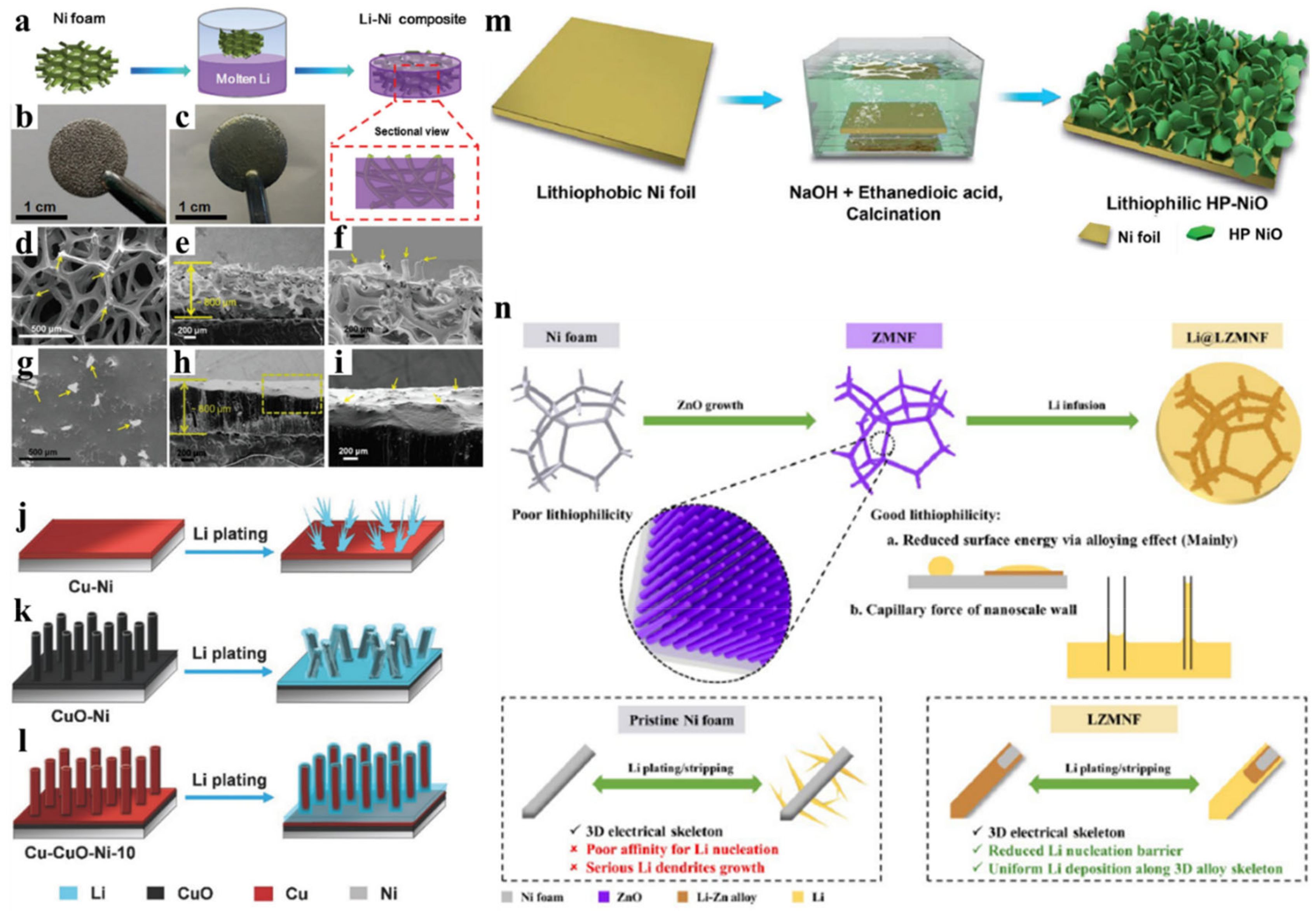
- Wu, S.; Zhang, Z.; Lan, M.; Yang, S.; Cheng, J.; Cai, J.; Shen, J.; Zhu, Y.; Zhang, K.; Zhang, W. Lithiophilic Cu-CuO-Ni Hybrid Structure: Advanced Current Collectors toward Stable Lithium Metal Anodes. Adv. Mater. 2018, 30, 1705830. [Google Scholar] [CrossRef]
- Xie, K.; Wei, W.; Yuan, K.; Lu, W.; Guo, M.; Li, Z.; Song, Q.; Liu, X.; Wang, J.-G.; Shen, C. Toward dendrite-free lithium deposition via structural and interfacial synergistic effects of 3D graphene@ Ni scaffold. ACS Appl. Mater. Interfaces 2016, 8, 26091–26097. [Google Scholar] [CrossRef]
- Ye, H.; Xin, S.; Yin, Y.-X.; Li, J.-Y.; Guo, Y.-G.; Wan, L.-J. Stable Li plating/stripping electrochemistry realized by a hybrid Li reservoir in spherical carbon granules with 3D conducting skeletons. J. Am. Chem. Soc. 2017, 139, 5916–5922. [Google Scholar] [CrossRef]
- Kang, H.-K.; Woo, S.-G.; Kim, J.-H.; Lee, S.-R.; Lee, D.-G.; Yu, J.-S. Three-dimensional monolithic corrugated graphene/Ni foam for highly stable and efficient Li metal electrode. J. Power Sources 2019, 413, 467–475. [Google Scholar] [CrossRef]
- Zhang, X.; Wang, A.; Lv, R.; Luo, J. A corrosion-resistant current collector for lithium metal anodes. Energy Storage Mater. 2019, 18, 199–204. [Google Scholar] [CrossRef]
- Huang, K.; Li, Z.; Xu, Q.; Liu, H.; Li, H.; Wang, Y. Lithiophilic CuO Nanoflowers on Ti-Mesh Inducing Lithium Lateral Plating Enabling Stable Lithium-Metal Anodes with Ultrahigh Rates and Ultralong Cycle Life. Adv. Energy Mater. 2019, 9, 1900853. [Google Scholar] [CrossRef]
- Lee, H.; Song, J.; Kim, Y.-J.; Park, J.-K.; Kim, H.-T. Structural modulation of lithium metal-electrolyte interface with three-dimensional metallic interlayer for high-performance lithium metal batteries. Sci. Rep. 2016, 6, 1–10. [Google Scholar] [CrossRef] [PubMed]
- Zheng, G.; Lee, S.W.; Liang, Z.; Lee, H.-W.; Yan, K.; Yao, H.; Wang, H.; Li, W.; Chu, S.; Cui, Y. Interconnected hollow carbon nanospheres for stable lithium metal anodes. Nat. Nanotechnol. 2014, 9, 618–623. [Google Scholar] [CrossRef] [PubMed]
- Zhang, A.; Fang, X.; Shen, C.; Liu, Y.; Zhou, C. A carbon nanofiber network for stable lithium metal anodes with high Coulombic efficiency and long cycle life. Nano Res. 2016, 9, 3428–3436. [Google Scholar] [CrossRef]
- Matsuda, S. The effect of electrical conductivity on lithium metal deposition in 3D carbon nanofiber matrices. Carbon 2019, 154, 370–374. [Google Scholar] [CrossRef]
- Sun, Z.; Jin, S.; Jin, H.; Du, Z.; Zhu, Y.; Cao, A.; Ji, H.; Wan, L.J. Robust Expandable Carbon Nanotube Scaffold for Ultrahigh-Capacity Lithium-Metal Anodes. Adv. Mater. 2018, 30, 1800884. [Google Scholar] [CrossRef]
- Cheng, X.-B.; Peng, H.-J.; Huang, J.-Q.; Zhang, R.; Zhao, C.-Z.; Zhang, Q. Dual-phase lithium metal anode containing a polysulfide-induced solid electrolyte interphase and nanostructured graphene framework for lithium–sulfur batteries. ACS Nano 2015, 9, 6373–6382. [Google Scholar] [CrossRef]
- Lin, D.; Liu, Y.; Liang, Z.; Lee, H.-W.; Sun, J.; Wang, H.; Yan, K.; Xie, J.; Cui, Y. Layered reduced graphene oxide with nanoscale interlayer gaps as a stable host for lithium metal anodes. Nat. Nanotechnol. 2016, 11, 626–632. [Google Scholar] [CrossRef]
- Zhang, R.; Cheng, X.B.; Zhao, C.Z.; Peng, H.J.; Shi, J.L.; Huang, J.Q.; Wang, J.; Wei, F.; Zhang, Q. Conductive nanostructured scaffolds render low local current density to inhibit lithium dendrite growth. Adv. Mater. 2016, 28, 2155–2162. [Google Scholar] [CrossRef]
- Jin, S.; Sun, Z.; Guo, Y.; Qi, Z.; Guo, C.; Kong, X.; Zhu, Y.; Ji, H. High areal capacity and lithium utilization in anodes made of covalently connected graphite microtubes. Adv. Mater. 2017, 29, 1700783. [Google Scholar] [CrossRef]
- Liu, S.; Wang, A.; Li, Q.; Wu, J.; Chiou, K.; Huang, J.; Luo, J. Crumpled graphene balls stabilized dendrite-free lithium metal anodes. Joule 2018, 2, 184–193. [Google Scholar] [CrossRef]
- Qian, J.; Li, Y.; Zhang, M.; Luo, R.; Wang, F.; Ye, Y.; Xing, Y.; Li, W.; Qu, W.; Wang, L. Protecting lithium/sodium metal anode with metal-organic framework based compact and robust shield. Nano Energy 2019, 60, 866–874. [Google Scholar] [CrossRef]
- Yan, K.; Lu, Z.; Lee, H.-W.; Xiong, F.; Hsu, P.-C.; Li, Y.; Zhao, J.; Chu, S.; Cui, Y. Selective deposition and stable encapsulation of lithium through heterogeneous seeded growth. Nat. Energy 2016, 1, 16010. [Google Scholar] [CrossRef]
- Wang, C.; Xie, H.; Zhang, L.; Gong, Y.; Pastel, G.; Dai, J.; Liu, B.; Wachsman, E.D.; Hu, L. Universal soldering of lithium and sodium alloys on various substrates for batteries. Adv. Energy Mater. 2018, 8, 1701963. [Google Scholar] [CrossRef]
- He, Y.; Zhang, Y.; Ding, F.; Li, X.; Wang, Z.; Lü, Z.; Wang, X.; Liu, Z.; Huang, X. Formation of hollow nanofiber rolls through controllable carbon diffusion for Li metal host. Carbon 2020, 157, 622–630. [Google Scholar] [CrossRef]
- Yang, C.; Yao, Y.; He, S.; Xie, H.; Hitz, E.; Hu, L. Ultrafine silver nanoparticles for seeded lithium deposition toward stable lithium metal anode. Adv. Mater. 2017, 29, 1702714. [Google Scholar] [CrossRef]
- Zhang, R.; Chen, X.; Shen, X.; Zhang, X.-Q.; Chen, X.-R.; Cheng, X.-B.; Yan, C.; Zhao, C.-Z.; Zhang, Q. Coralloid carbon fiber-based composite lithium anode for robust lithium metal batteries. Joule 2018, 2, 764–777. [Google Scholar] [CrossRef]
- Liu, T.; Hu, J.; Li, C.; Wang, Y. Unusual conformal Li plating on alloyable nanofiber frameworks to enable dendrite suppression of Li metal anode. ACS Appl. Energy Mater. 2019, 2, 4379–4388. [Google Scholar] [CrossRef]
- Hou, G.; Ren, X.; Ma, X.; Zhang, L.; Zhai, W.; Ai, Q.; Xu, X.; Zhang, L.; Si, P.; Feng, J. Dendrite-free Li metal anode enabled by a 3D free-standing lithiophilic nitrogen-enriched carbon sponge. J. Power Sources 2018, 386, 77–84. [Google Scholar] [CrossRef]
- Huang, G.; Han, J.; Zhang, F.; Wang, Z.; Kashani, H.; Watanabe, K.; Chen, M. Lithiophilic 3D Nanoporous Nitrogen-Doped Graphene for Dendrite-Free and Ultrahigh-Rate Lithium-Metal Anodes. Adv. Mater. 2019, 31, 1805334. [Google Scholar] [CrossRef]
- Zhang, R.; Chen, X.R.; Chen, X.; Cheng, X.B.; Zhang, X.Q.; Yan, C.; Zhang, Q. Lithiophilic sites in doped graphene guide uniform lithium nucleation for dendrite-free lithium metal anodes. Angew. Chem. Int. Ed. 2017, 56, 7764–7768. [Google Scholar] [CrossRef] [PubMed]
- Liu, L.; Yin, Y.X.; Li, J.Y.; Wang, S.H.; Guo, Y.G.; Wan, L.J. Uniform lithium nucleation/growth induced by lightweight nitrogen-doped graphitic carbon foams for high-performance lithium metal anodes. Adv. Mater. 2018, 30, 1706216. [Google Scholar] [CrossRef] [PubMed]
- Liu, Y.; Qin, X.; Zhang, S.; Huang, Y.; Kang, F.; Chen, G.; Li, B. Oxygen and nitrogen co-doped porous carbon granules enabling dendrite-free lithium metal anode. Energy Storage Mater. 2019, 18, 320–327. [Google Scholar] [CrossRef]
- Nan, Y.; Li, S.; Shi, Y.; Yang, S.; Li, B. Gradient-Distributed Nucleation Seeds on Conductive Host for a Dendrite-Free and High-Rate Lithium Metal Anode. Small 2019, 15, 1903520. [Google Scholar] [CrossRef] [PubMed]
- Zhang, Y.; Luo, W.; Wang, C.; Li, Y.; Chen, C.; Song, J.; Dai, J.; Hitz, E.M.; Xu, S.; Yang, C. High-capacity, low-tortuosity, and channel-guided lithium metal anode. Proc. Natl. Acad. Sci. USA 2017, 114, 3584–3589. [Google Scholar] [CrossRef]
- Xue, P.; Sun, C.; Li, H.; Liang, J.; Lai, C. Superlithiophilic Amorphous SiO2–TiO2 Distributed into Porous Carbon Skeleton Enabling Uniform Lithium Deposition for Stable Lithium Metal Batteries. Adv. Sci. 2019, 6, 1900943. [Google Scholar] [CrossRef]
- Lin, K.; Qin, X.; Liu, M.; Xu, X.; Liang, G.; Wu, J.; Kang, F.; Chen, G.; Li, B. Ultrafine titanium nitride sheath decorated carbon nanofiber network enabling stable lithium metal anodes. Adv. Funct. Mater. 2019, 29, 1903229. [Google Scholar] [CrossRef]
- Luo, L.; Li, J.; Yaghoobnejad Asl, H.; Manthiram, A. A 3D Lithiophilic Mo2N-Modified Carbon Nanofiber Architecture for Dendrite-Free Lithium-Metal Anodes in a Full Cell. Adv. Mater. 2019, 31, 1904537. [Google Scholar] [CrossRef]
- Wang, T.S.; Liu, X.; Zhao, X.; He, P.; Nan, C.W.; Fan, L.Z. Regulating Uniform Li Plating/Stripping via Dual-Conductive Metal-Organic Frameworks for High-Rate Lithium Metal Batteries. Adv. Funct. Mater. 2020, 30, 2000786. [Google Scholar] [CrossRef]
- Guo, Z.; Wang, F.; Li, Z.; Yang, Y.; Tamirat, A.G.; Qi, H.; Han, J.; Li, W.; Wang, L.; Feng, S. Lithiophilic Co/Co4N nanoparticles embedded in hollow N-doped carbon nanocubes stabilizing lithium metal anodes for Li-air batteries. J. Mater. Chem. A 2018, 6, 22096–22105. [Google Scholar] [CrossRef]
- Liu, W.; Mi, Y.; Weng, Z.; Zhong, Y.; Wu, Z.; Wang, H. Functional metal–organic framework boosting lithium metal anode performance via chemical interactions. Chem. Sci. 2017, 8, 4285–4291. [Google Scholar] [CrossRef] [PubMed]
- Wei, L.; Li, L.; Zhao, T.; Zhang, N.; Zhao, Y.; Wu, F.; Chen, R. MOF-derived lithiophilic CuO nanorod arrays for stable lithium metal anodes. Nanoscale 2020, 12, 9416–9422. [Google Scholar] [CrossRef] [PubMed]
- Liu, Y.; Lin, D.; Liang, Z.; Zhao, J.; Yan, K.; Cui, Y. Lithium-coated polymeric matrix as a minimum volume-change and dendrite-free lithium metal anode. Nat. Commun. 2016, 7, 10992. [Google Scholar] [CrossRef] [PubMed]
- Zhao, F.; Zhou, X.; Deng, W.; Liu, Z. Entrapping lithium deposition in lithiophilic reservoir constructed by vertically aligned ZnO nanosheets for dendrite-free Li metal anodes. Nano Energy 2019, 62, 55–63. [Google Scholar] [CrossRef]
- Zhang, Y.; Wang, C.; Pastel, G.; Kuang, Y.; Xie, H.; Li, Y.; Liu, B.; Luo, W.; Chen, C.; Hu, L. 3D Wettable Framework for Dendrite-Free Alkali Metal Anodes. Adv. Energy Mater. 2018, 8, 1800635. [Google Scholar] [CrossRef]
- Zhang, Q.; Luan, J.; Sun, D.; Tang, Y.; Wang, H. Plasma-treated Ti3+-doped sodium titanate nanosheet arrays on titanium foil as a lithiophilic current collector for a stable lithium metal anode. Chem. Commun. 2019, 55, 6551–6554. [Google Scholar] [CrossRef]
- Dong, Q.; Hong, B.; Fan, H.; Jiang, H.; Zhang, K.; Lai, Y. Inducing the Formation of In Situ Li3N-Rich SEI via Nanocomposite Plating of Mg3N2 with Lithium Enables High-Performance 3D Lithium-Metal Batteries. ACS Appl. Mater. Interfaces 2019, 12, 627–636. [Google Scholar] [CrossRef]
- Lei, M.; Wang, J.-G.; Ren, L.; Nan, D.; Shen, C.; Xie, K.; Liu, X. Highly Lithiophilic Cobalt Nitride Nanobrush as a Stable Host for High-Performance Lithium Metal Anodes. ACS Appl. Mater. Interfaces 2019, 11, 30992–30998. [Google Scholar] [CrossRef]
- Shi, P.; Li, T.; Zhang, R.; Shen, X.; Cheng, X.B.; Xu, R.; Huang, J.Q.; Chen, X.R.; Liu, H.; Zhang, Q. Lithiophilic LiC6 layers on carbon hosts enabling stable Li metal anode in working batteries. Adv. Mater. 2019, 31, 1807131. [Google Scholar] [CrossRef]
- Niu, C.; Pan, H.; Xu, W.; Xiao, J.; Zhang, J.-G.; Luo, L.; Wang, C.; Mei, D.; Meng, J.; Wang, X. Self-smoothing anode for achieving high-energy lithium metal batteries under realistic conditions. Nat. Nanotechnol. 2019, 14, 594–601. [Google Scholar] [CrossRef]
- Chen, Y.; Ke, X.; Cheng, Y.; Fan, M.; Wu, W.; Huang, X.; Liang, Y.; Zhong, Y.; Ao, Z.; Lai, Y. Boosting the electrochemical performance of 3D composite lithium metal anodes through synergistic structure and interface engineering. Energy Storage Mater. 2020, 26, 56–64. [Google Scholar] [CrossRef]
- Liu, K.; Li, Z.; Xie, W.; Li, J.; Rao, D.; Shao, M.; Zhang, B.; Wei, M. Oxygen-rich carbon nanotube networks for enhanced lithium metal anode. Energy Storage Mater. 2018, 15, 308–314. [Google Scholar] [CrossRef]


| Metal-Based Porous Framework | Methods/Modifications for Creating a Porous Structure | Electrochemical Performance | Ref. |
|---|---|---|---|
| Micropatterned-Li | Microneedle | Improved rate capability and cycling stability by 20% and 200%, respectively. | [17] |
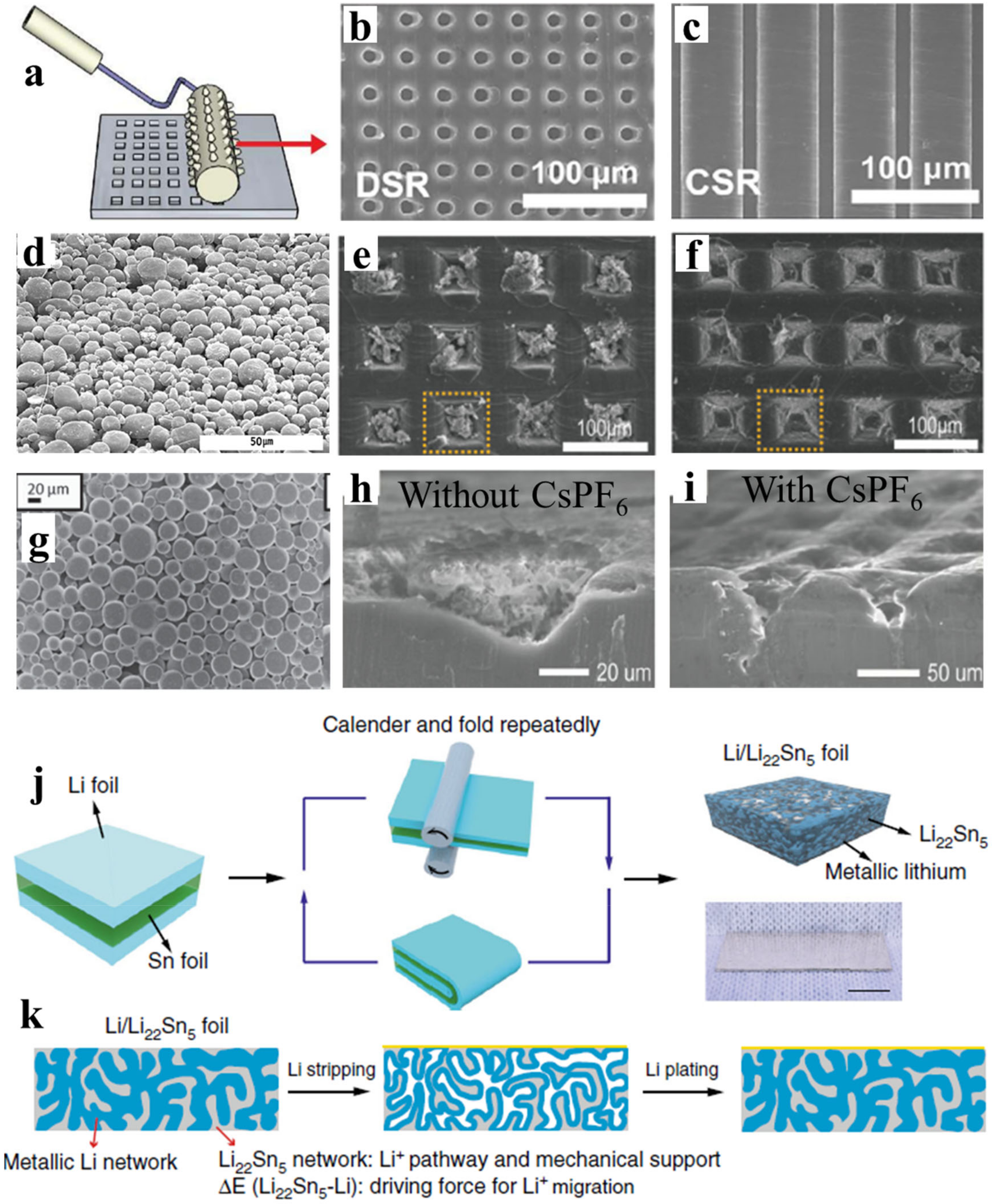
| CSR/DSR Li | Lithography | Stable Li plating/stripping up to 10 mA cm−2 and improved cycling performance at 10 C | [18] |
| Micropatterned-Li | Pressing/coating of μm-sized Li powder | Cycling performance and dendrite-free Li deposition shows the possibility to replace anode with excess Li. | [19,21] |
| Micropatterned-Li | μm-scale pyramid reliefs | Reversible Li plating/stripping | [20] |
| Micropatterned-Li | Microneedle + CsPF6 additive | Provides self-healing electrostatic shield | [22] |
| 3D nanostructured-Li | calendaring and folding | 20 mV overpotential for 200 cycles at 20 mA cm−2 | [25] |
| 3D sub-micron sized Cu | ammonia solution process | <50 mV polarization after 600 h cycling, CE 98.5% at 0.5 mA cm−2 | [9] |
| 3D CuNW | alkaline solution process | Plating of 7.5 mAh cm−2 of Li, CE 98.6% during 200 cycles at 1 mA cm−2 | [26] |
| 3D porous Cu | Dealloying of brass–ammonium chloride solution process | CE 97% for 250 cycles at 0.5 mA cm−2 | [27] |
| 3D porous Cu | Linear sweep voltammetry in acidic solution | 20 mV polarization, stable 400 h plating/stripping at 1 mA cm−2 | [28] |
| 3D porous Cu | Vacuum distillation-(400–900) °C | 800 h plating/stripping at 0.52 mA cm−2 | [29] |
| Microcompartmented-Cu | hot lamination, laser ablation, and alkaline etching | CE 99% after 150 cycles at 0.5 mA cm−2. | [30] |
| VA-microchannel-Cu | Laser microprocessing | 20 mV polarization, CE 98.5 within 200 cycles at 1 at 1 mA cm−2 | [31] |
| 3D porous Cu/Li-metal composite | mechanical press or folding | 60 mV polarization, CE 93.8% after 100 cycles at 0.5 mA cm−2 | [32] |
| Vertically oriented Li-Cu-Li arrays | rolling-folding-winding | Deep charging up to 50 mAh cm−2, 2000 h plating/stripping at 1 mA cm−2 | [33] |
| Ni-foam | Molten Li infusion | Stable cycling for >100 cycles with reduced hysteresis at 5 mA cm−2 | [55] |
| 3D porous Ti | Directly purchased | CE 99% at 1 mAcm−2 | [70] |
| Carbon-Based Porous Framework | Methods/Modifications | Electrochemical Performance | Ref. |
|---|---|---|---|
| carbon-nanospheres | Template-based (dropcasting/c-coating-annealing-etching) | CE 97.5% for > 150 cycles at 1 mA cm−2. | [73] |
| CNF film | Graphitized at 3000 °C-Vacuum filtration | CE 99.9% up to 300 cycles at 1 mA cm−2 | [74] |
| CNT | Floating-catalyst-chemical-vapor-deposition | CE 97.5 % for 100 cycles at 1 mA cm−2 | [76] |
| graphene | Chemical vapor deposition-chemical solution-annealing | CE 93% up to 50 cycles at 2 mA cm−2 | [79] |
| Li/r-GO | Vacuum filtration-sparked reaction-molten Li infusion | 80 mV overpotential at 3 mA cm−2 | [78] |
| Carbonized MOFs | Chemical solution-pyrolysis | CE 91.5 % after 130 cycles at 10 mA cm−2 | [99] |
| Lithiophilic Materials-Type | Examples-Forms/Structures | Ref. |
|---|---|---|
| organic compound coating | [50] | |
| Metal oxides | ZnO quantum dots, ZnO NA, ZnO layer, VA ZnO NSs, NiO, CuO nanorod array, CuO-VA-NA, CuO NSs, SnO2 coating, NaTiO3 -NS array | [18,37,38,39,40,41,42,59,60,61,62,102,103,104,105,106] |
| Metal nitrides | Ni3N layer, TiN sheath, Mo2N particles, Mg3N2 deposition, CoN nanobrush | [43,44,64,97,107,108] |
| Metal sulfides | Cu2S-NW | [46] |
| Metal fluorides | NiFx NSs | [63] |
| Metal phosphides | Cu3P gradient | [47] |
| Metal carbides | LiC6 layer | [109] |
| oxynitride | CuON-NA | [45] |
| Functional group/N-doping | -SO3H, -NH2, -NH, -PO4, -Si-O | [48,49,50,51,91,110] |
| metal seeds/layers | Si coating, Au NPs, ultrafine Ag NPs, copper clad thin layer, nanoporous gold film | [8,35,36,57,83,84,111] |
| polymer | Polydopamine thin layer | [56] |
| Oxygen-rich porous matrix | Ketonic (C=O) group | [112] |
© 2020 by the authors. Licensee MDPI, Basel, Switzerland. This article is an open access article distributed under the terms and conditions of the Creative Commons Attribution (CC BY) license (http://creativecommons.org/licenses/by/4.0/).
Share and Cite
Pathak, R.; Zhou, Y.; Qiao, Q. Recent Advances in Lithiophilic Porous Framework toward Dendrite-Free Lithium Metal Anode. Appl. Sci. 2020, 10, 4185. https://doi.org/10.3390/app10124185
Pathak R, Zhou Y, Qiao Q. Recent Advances in Lithiophilic Porous Framework toward Dendrite-Free Lithium Metal Anode. Applied Sciences. 2020; 10(12):4185. https://doi.org/10.3390/app10124185
Chicago/Turabian StylePathak, Rajesh, Yue Zhou, and Qiquan Qiao. 2020. "Recent Advances in Lithiophilic Porous Framework toward Dendrite-Free Lithium Metal Anode" Applied Sciences 10, no. 12: 4185. https://doi.org/10.3390/app10124185
APA StylePathak, R., Zhou, Y., & Qiao, Q. (2020). Recent Advances in Lithiophilic Porous Framework toward Dendrite-Free Lithium Metal Anode. Applied Sciences, 10(12), 4185. https://doi.org/10.3390/app10124185