A New Formulation for Predicting the Collision Damage of Steel Stiffened Cylinders Subjected to Dynamic Lateral Mass Impact

 ,
,  ,
,  , ,
, ,
Abstract
1. Introduction
2. Numerical Analysis
2.1. Description of Test Data
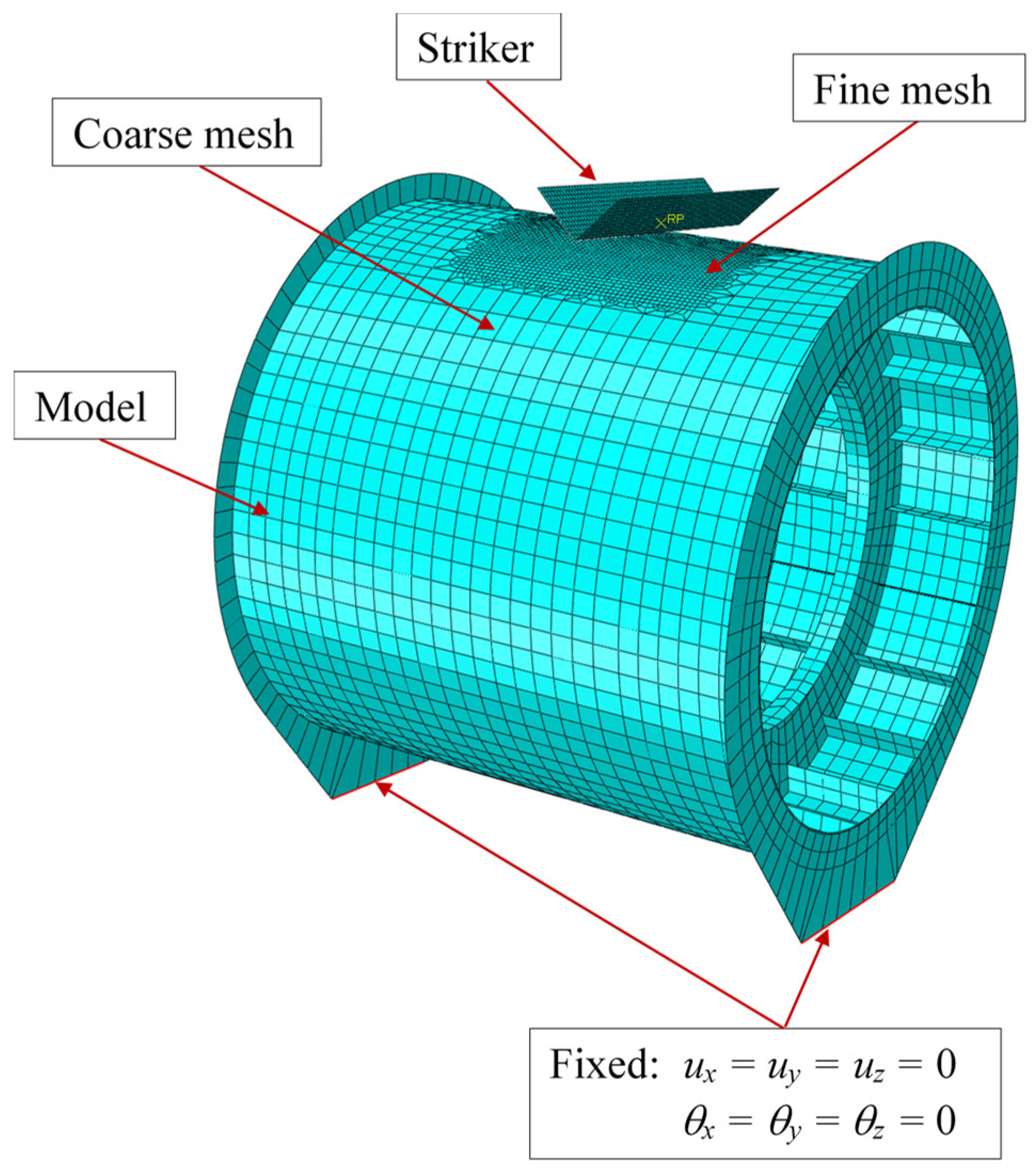
2.2. Finite Element Modelling
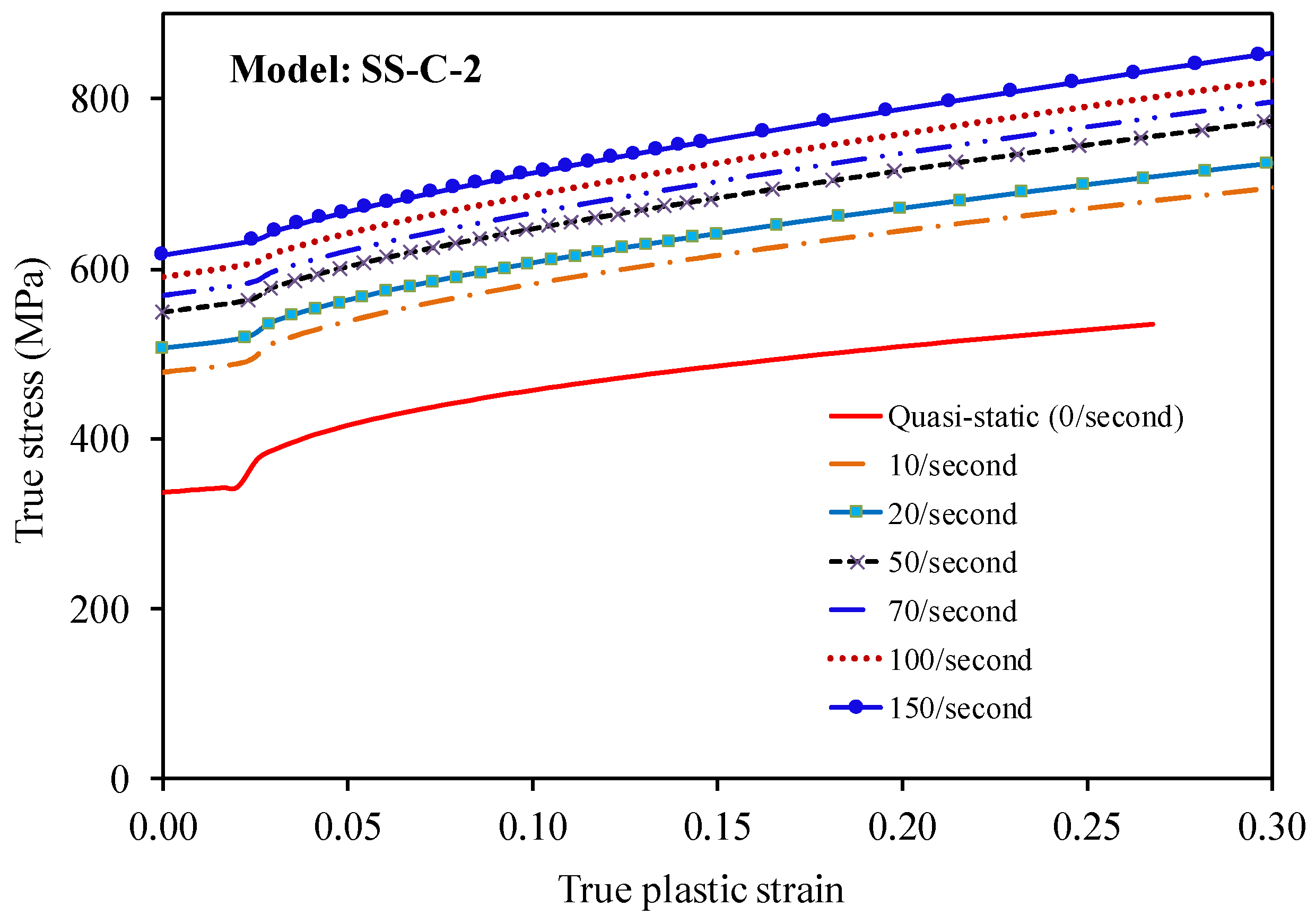
2.3. Material Properties
- σtr, εtr: true stress and strain, respectively;
- σY,tr, σHS,tr, σT,tr: true yield strength, true hardening start stress, and true ultimate tensile strength, respectively;
- εHS,tr, εT,tr: true hardening start strain and true ultimate tensile strain, respectively;
- σTD, σYD: dynamic ultimate tensile strength and dynamic yield strength, respectively;
- εT, εTD: ultimate tensile strain and dynamic ultimate tensile strain, respectively;
- εHSD, εHSS: dynamic hardening start strain and static hardening start strain, respectively; and
- εY,: yield strain and equivalent strain rate, respectively.
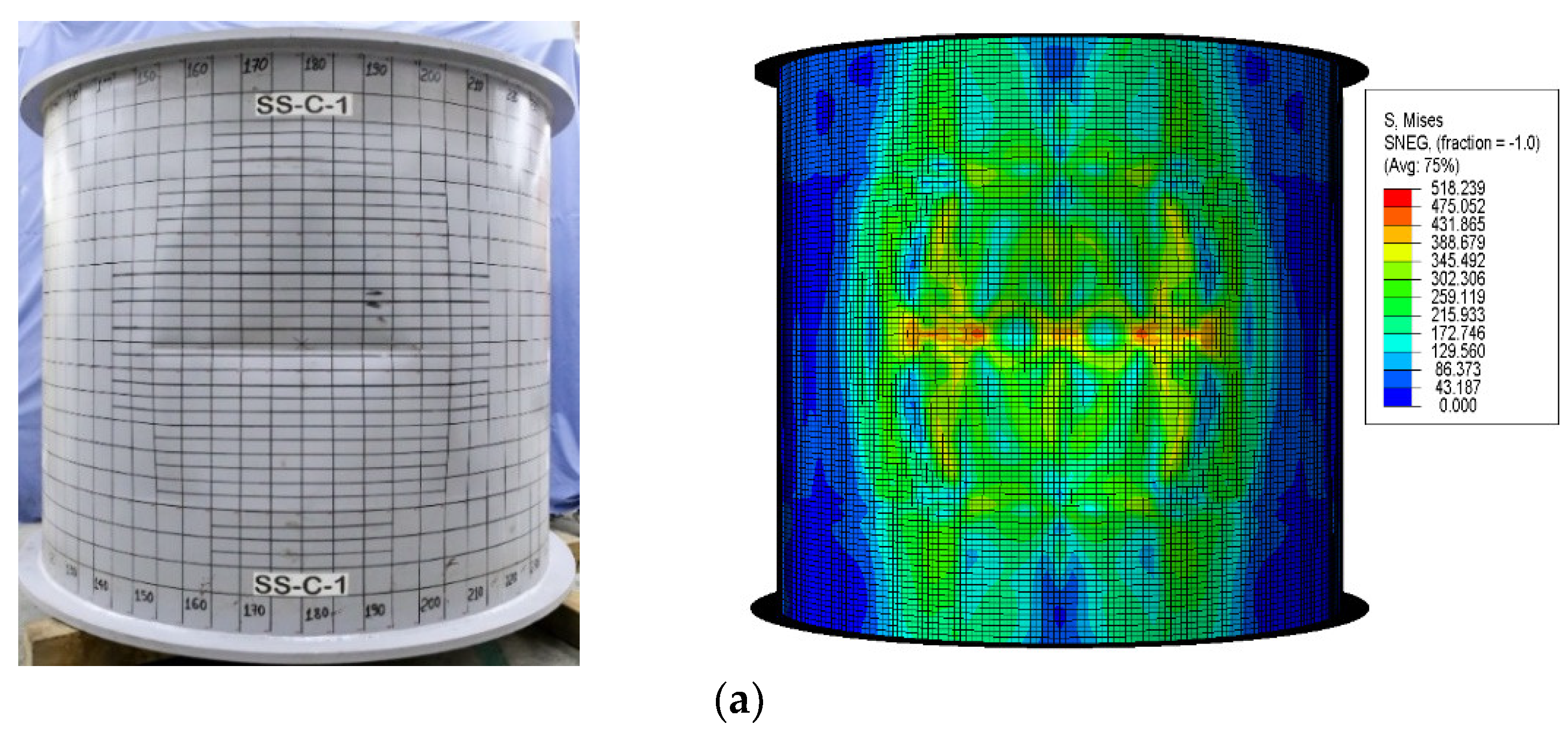
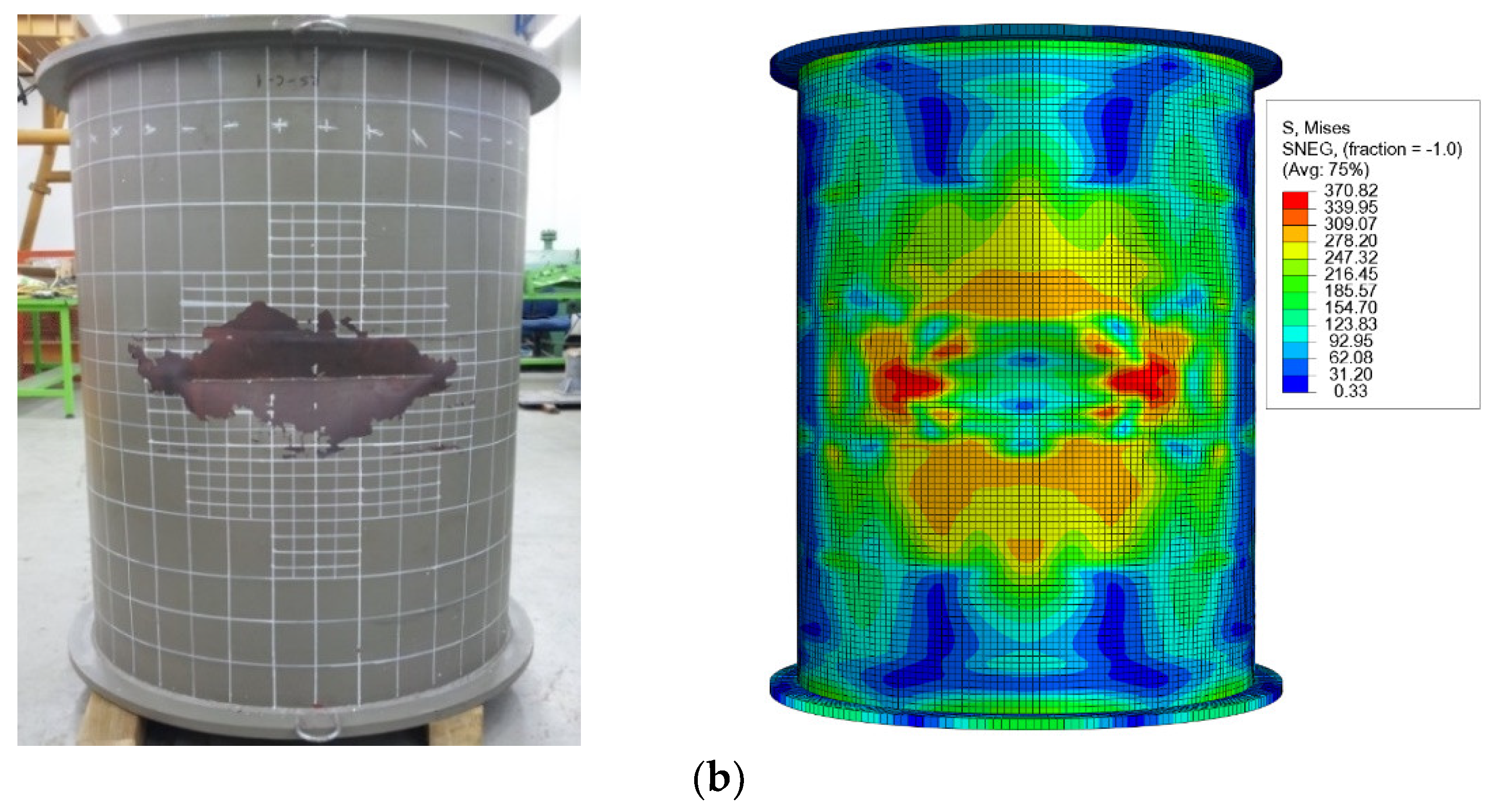
2.4. Benchmarking Numerical Predictions with Test Results
3. Case Studies
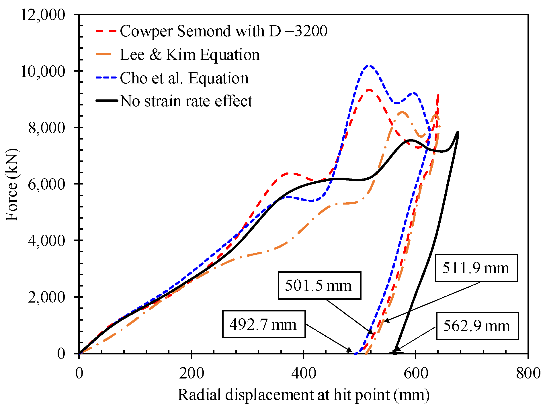
3.1. Effect of Strain-Rate Hardening Definition
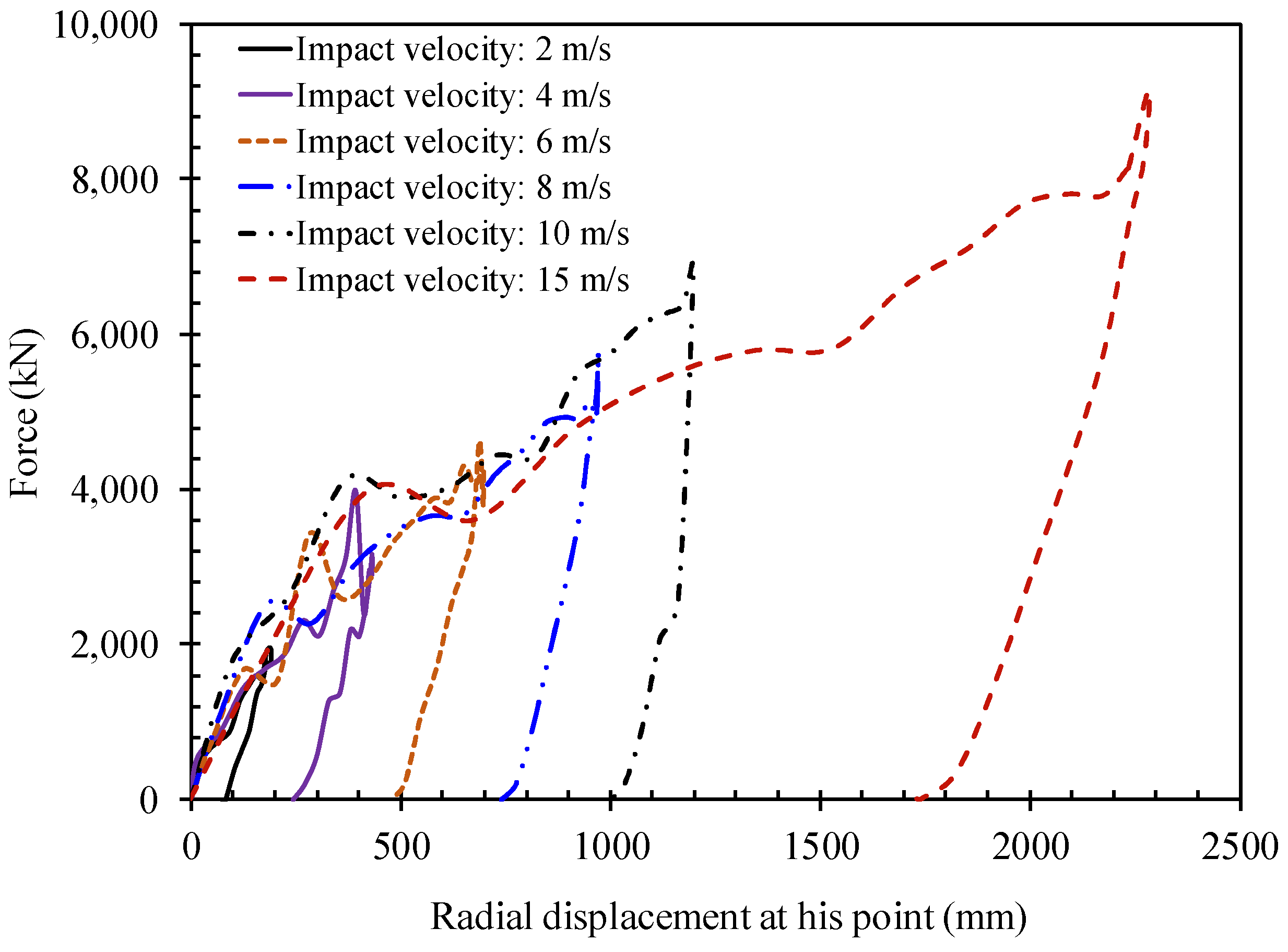
3.2. Effect of Impact Velocities
3.3. Effect of Impact Locations
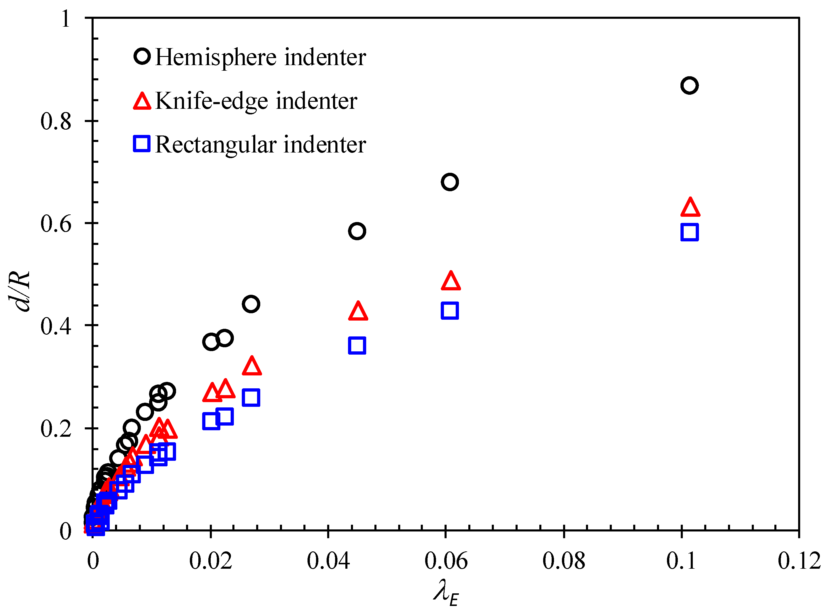
3.4. Effect of Striker Header Shapes
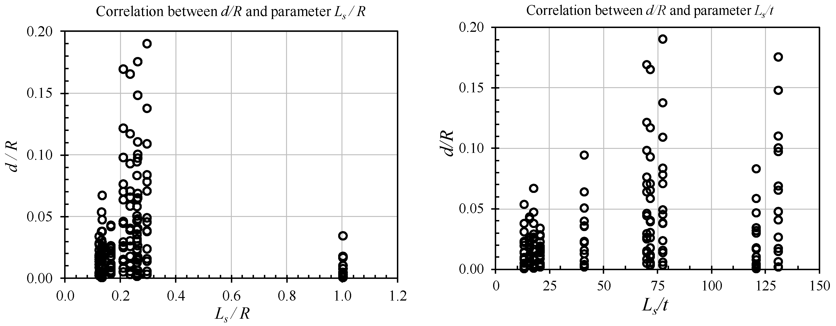
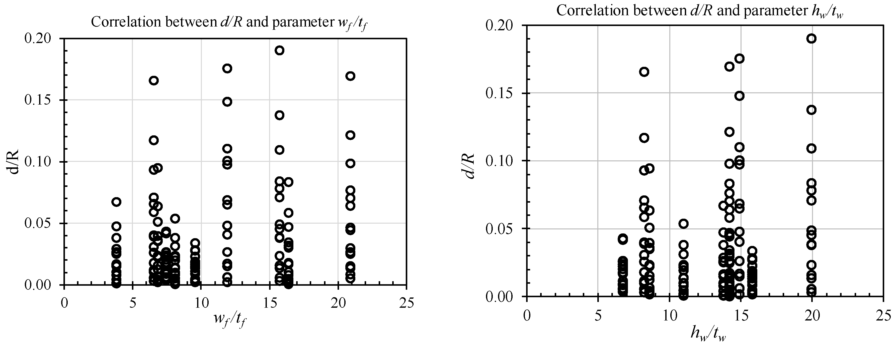
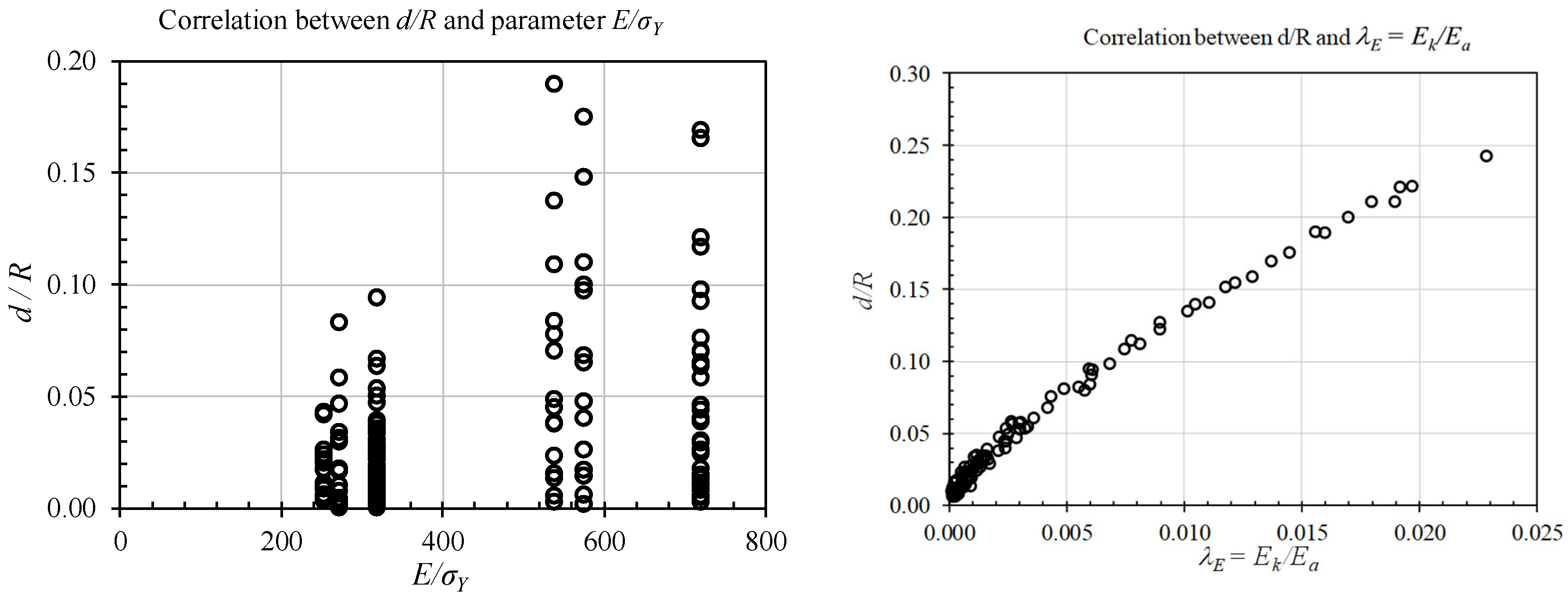
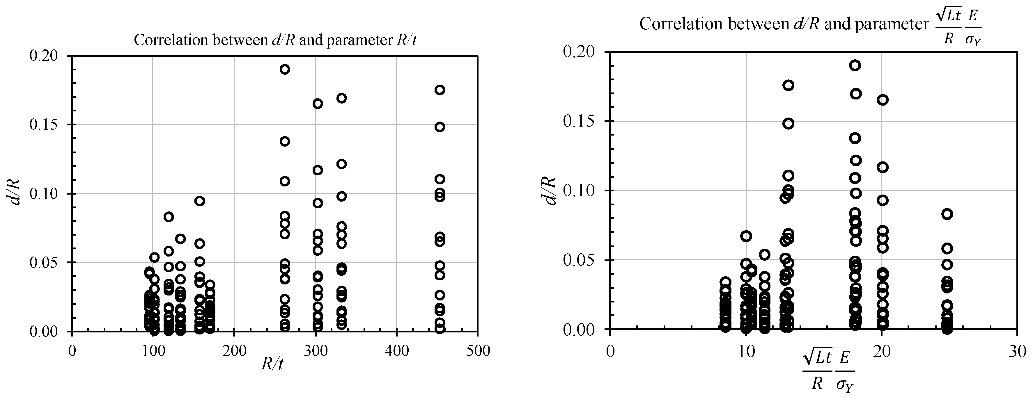
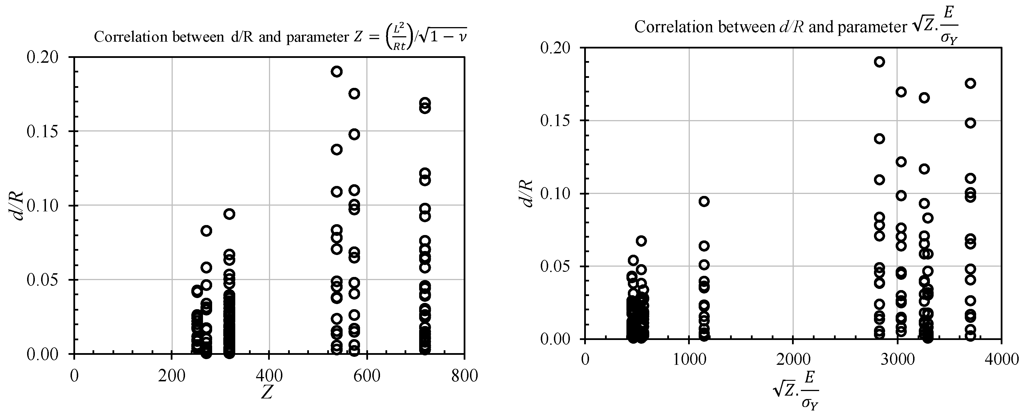
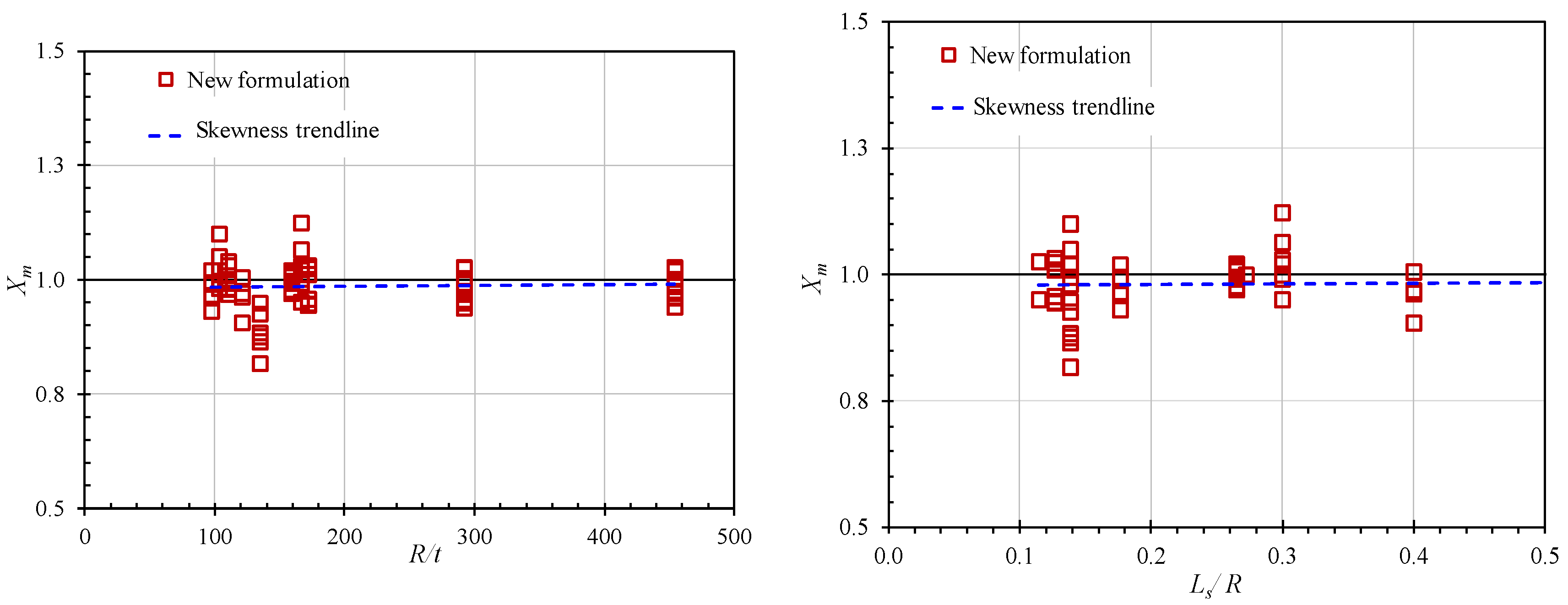
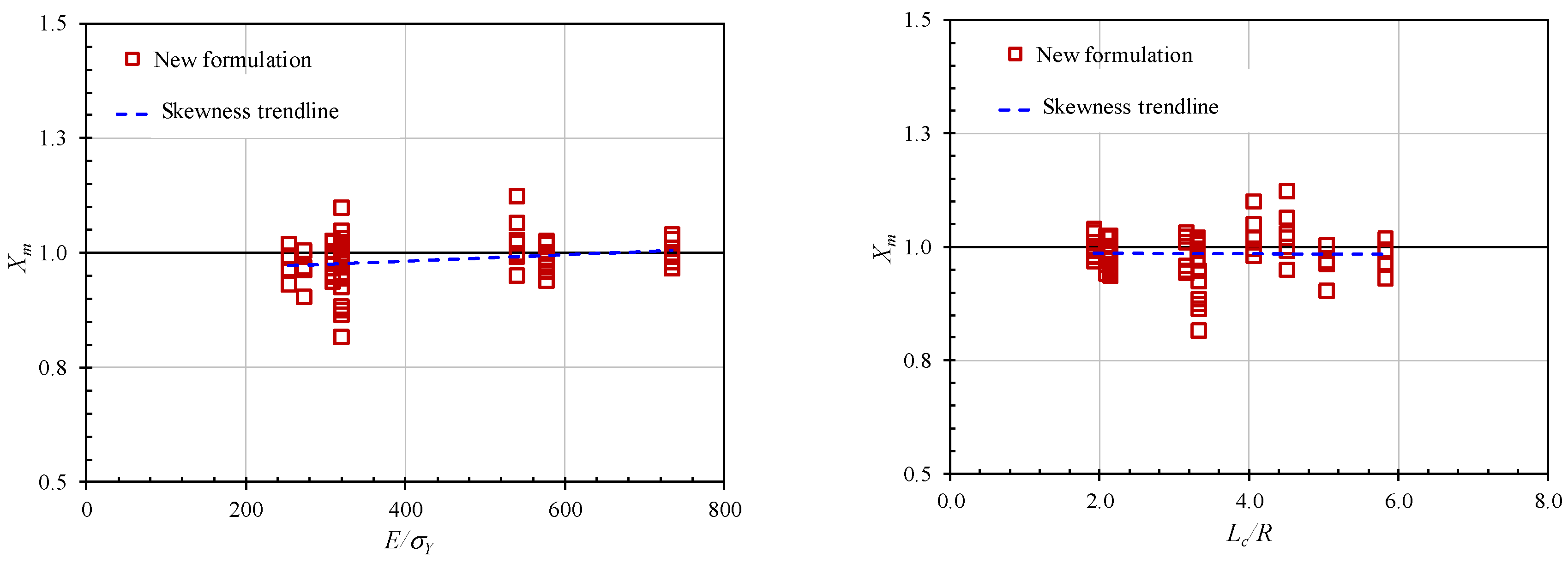
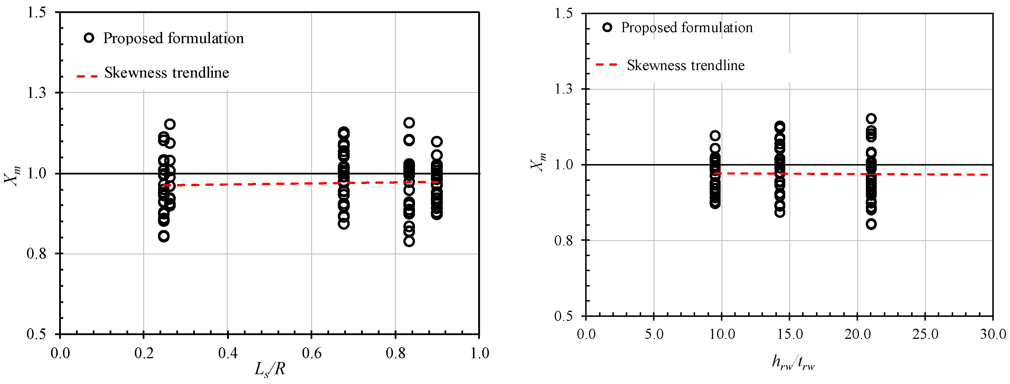
4. Derivation of Empirical Formulation
- ○
- Step 1: Selecting the scantling of actual design example ring- and/or stringer-stiffened cylinders.
- ○
- Step 2: Performing finite element analysis to assess the collision response of each model.
- ○
- Step 3: Preparation of non-dimensional form of geometric properties and collision loadings for applying in the derived formulations.
- ○
- Step 4: Checking the degree of dependence of explanatory variables.
- ○
- Step 5: Performing the regression analysis to find the best-fit curve by using the strongly-influenced parameters in the previous step.
- ○
- Step 6: Checking the accuracy of the proposed formulations.
- ○
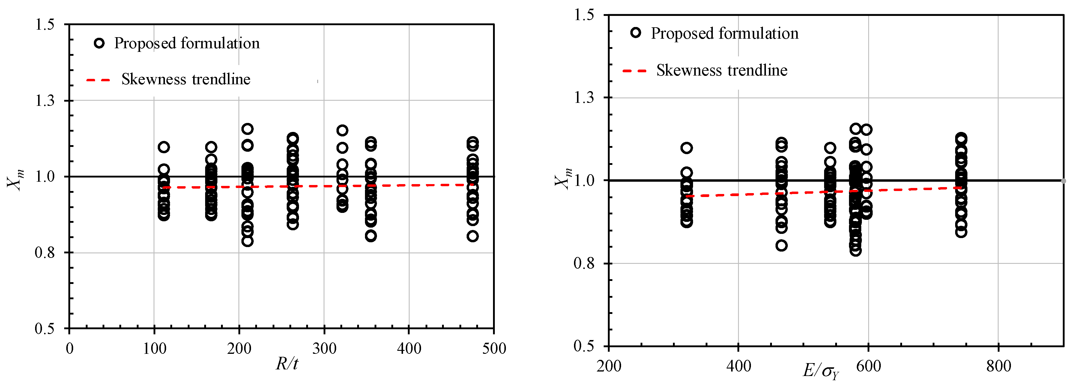
- Step 7: Checking the skewness of Xm (ratio of the numerical results to the proposed formulation results) against the basic parameters.
4.1. Ring-Stiffened Cylinder
- CS: indenter shape factor (CS = 1: Hemisphere indenter; CS = 0.81: Knife-edge indenter;
- CS = 0.68: Rectangular indenter),
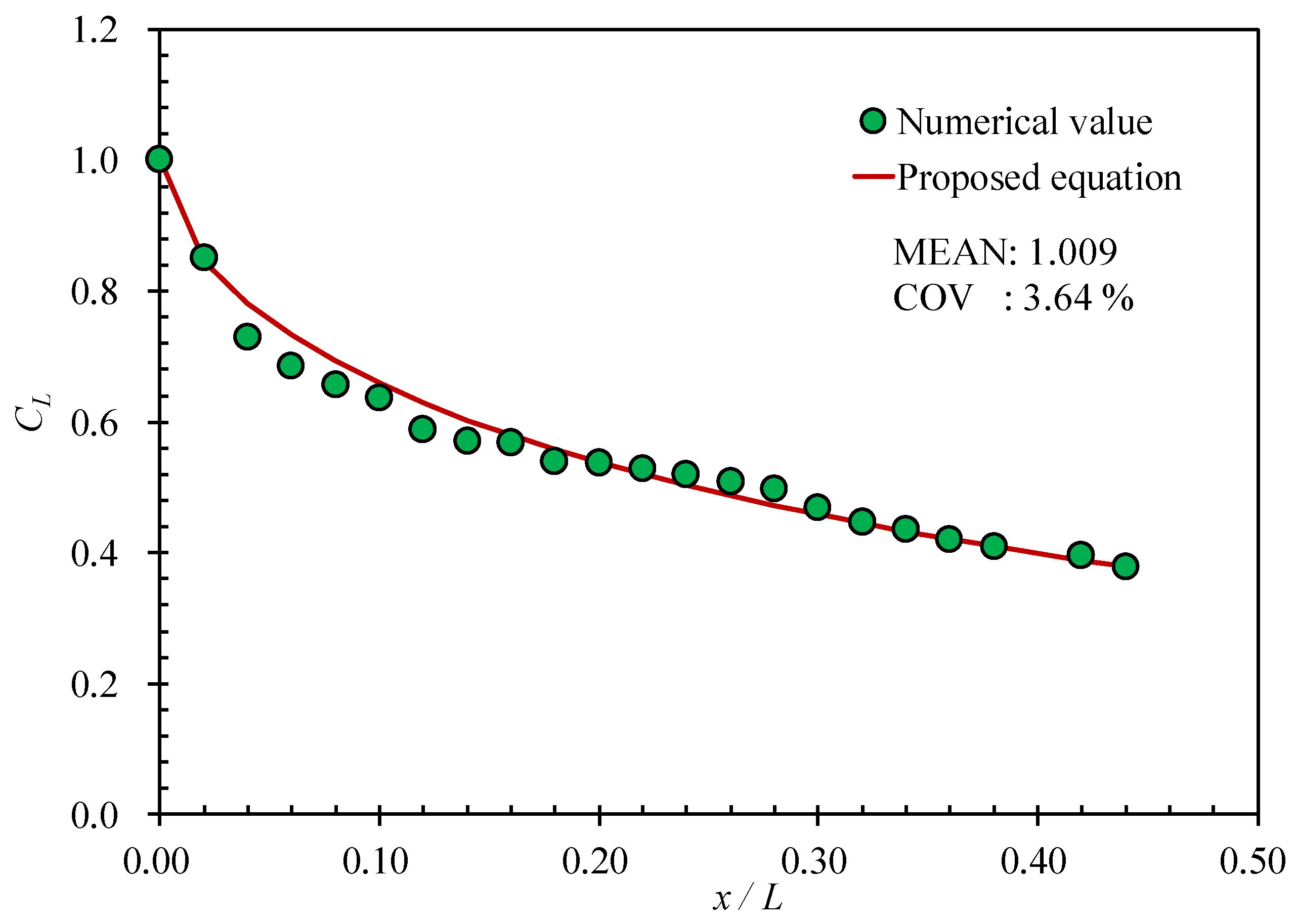
- CL: impact location factor, and
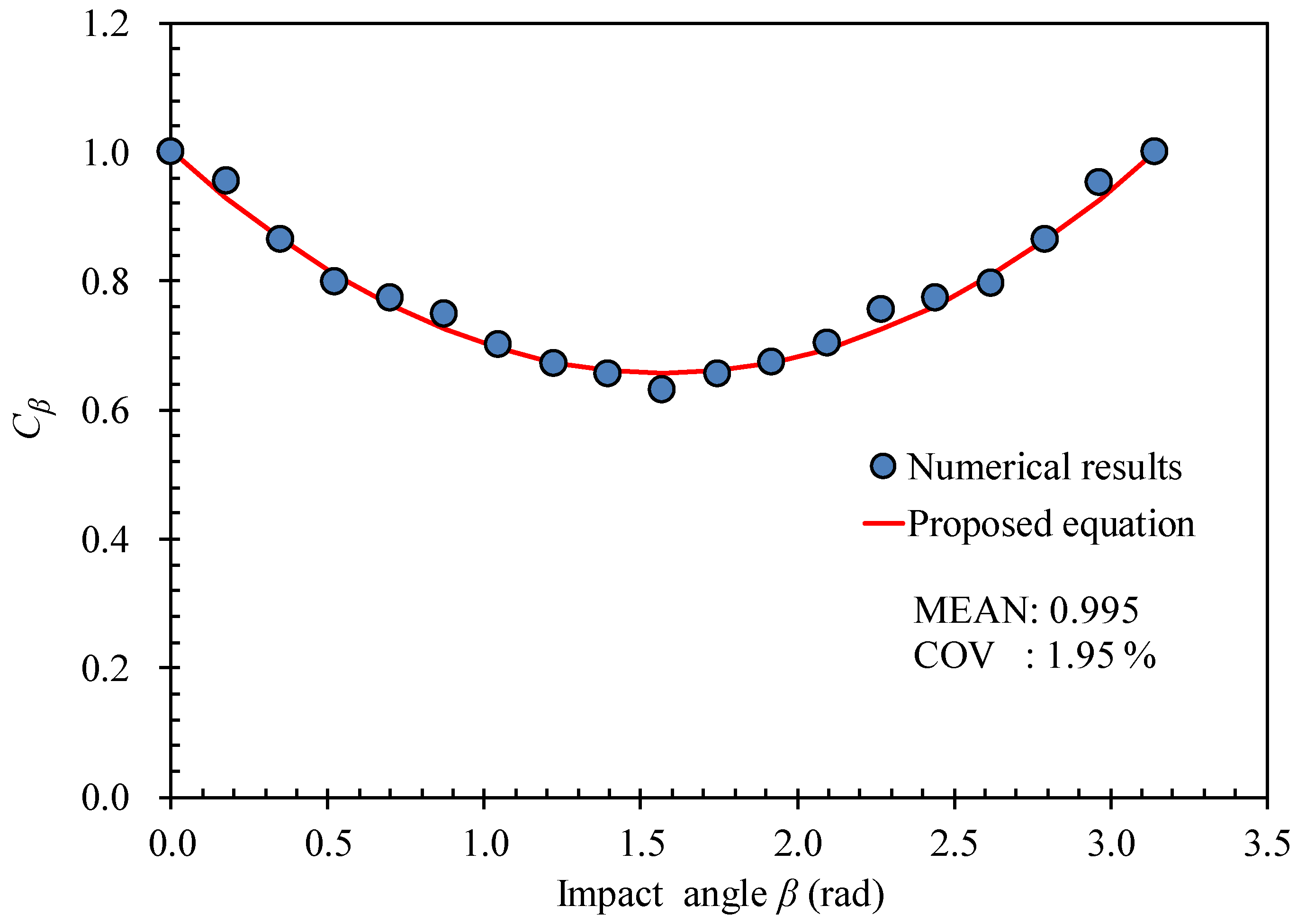
- Cβ: impact angle factor.
- x: distance from collision to mid-span of the ring-stiffened cylinder,
- L: total length of the ring-stiffened cylinder, and
- β: impact angle (rad)
- For general structural steel:
- For marine structural steel:
4.2. Stringer-Stiffened Cylinder
- CS: indenter shape factor (CS = 1: Hemisphere indenter; CS = 0.74: Knife-edge indenter;
- CS = 0.63: Rectangular indenter),
- CL: impact location factor, and
- Cβ: impact angle factor.
5. Accuracy of the Proposed Formulation
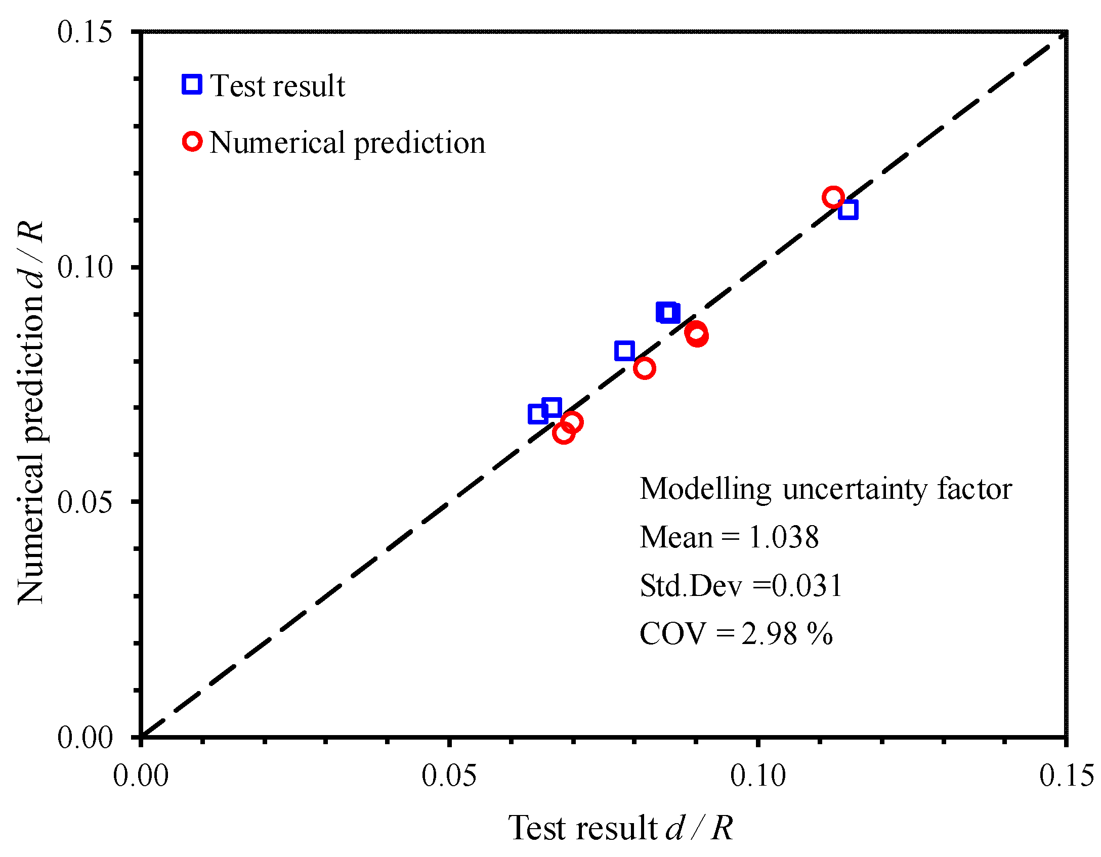
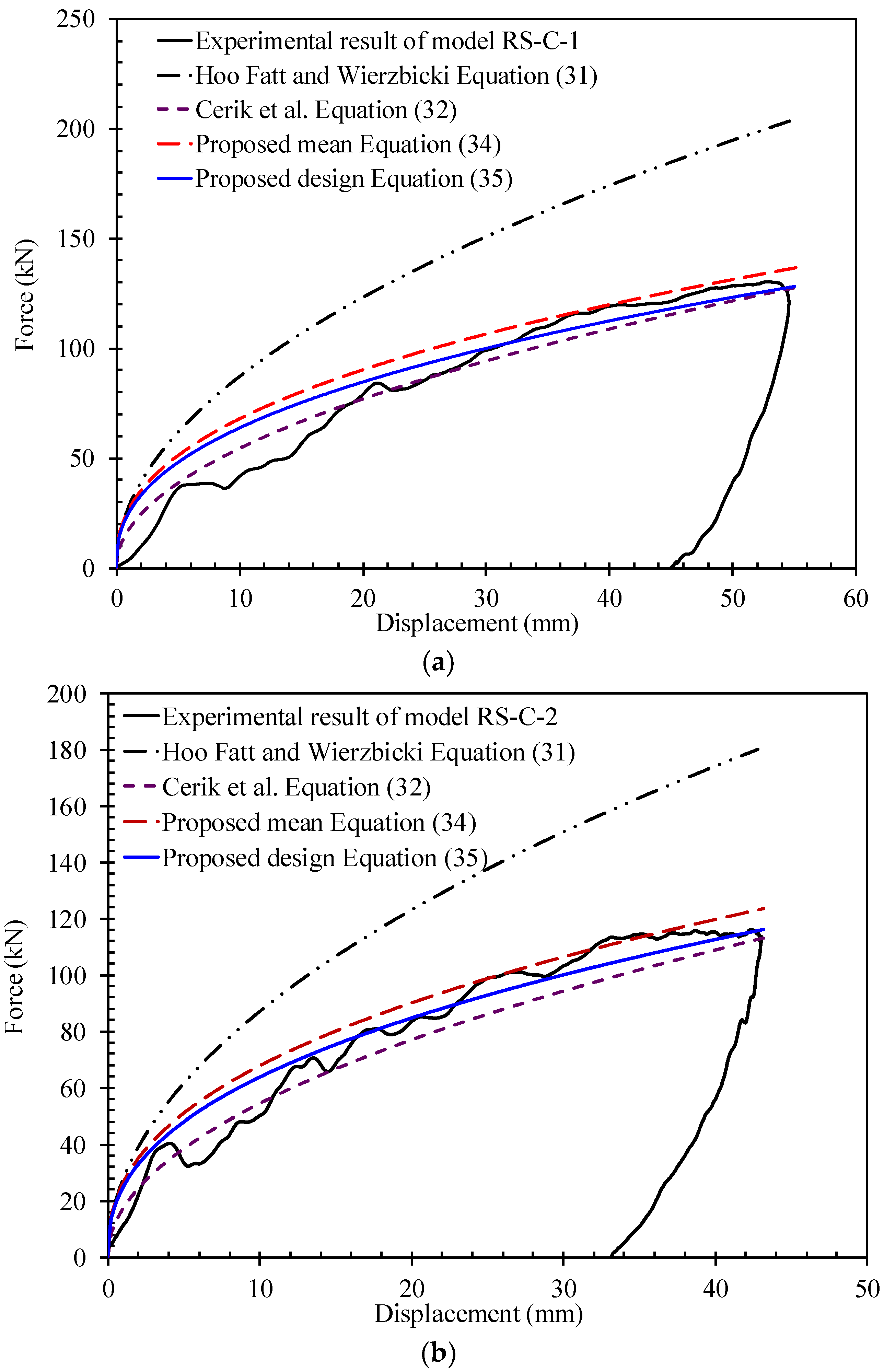
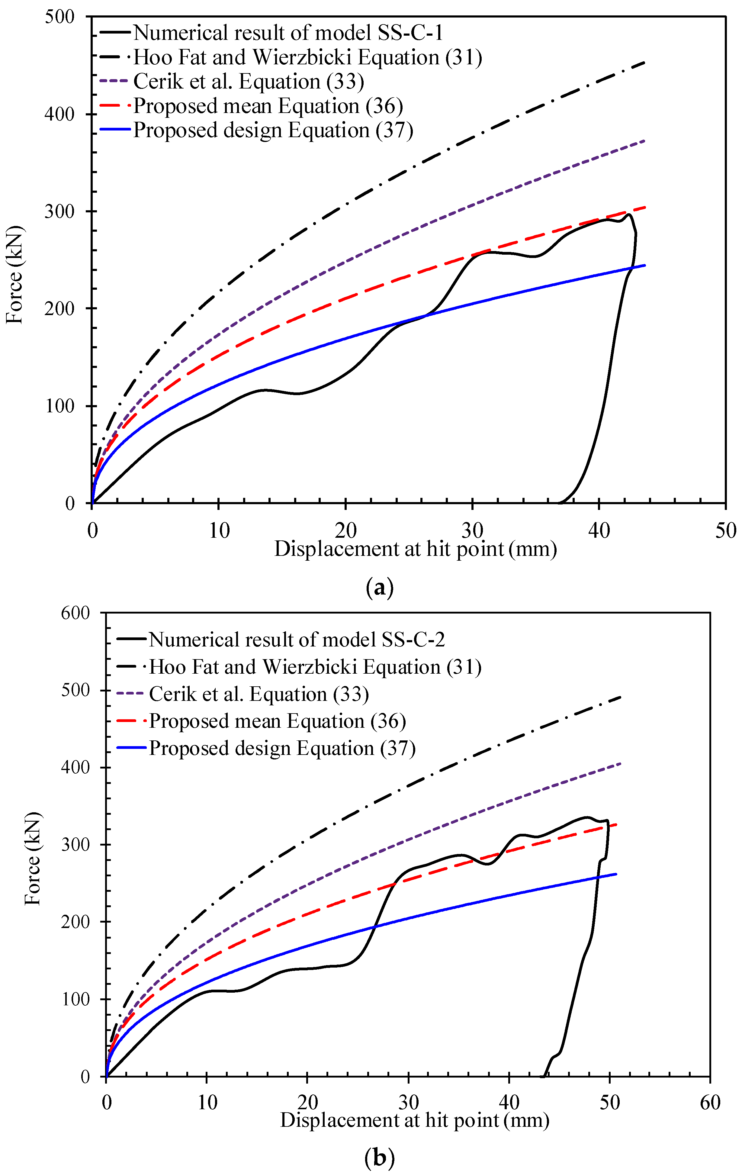
5.1. Comparison with Available Test Results
5.2. Comparison with Other Existing Formulae
- Ring-stiffened cylinder:
- Stringer-stiffened cylinder:
6. Concluding Remarks
- For the first time, the simple design equations to predict the maximum permanent local dent depth of a stiffened cylinder subjected to dynamic mass impact were successfully conducted in this study. In these equations, all effect parameters such as impact location factor, impact angle factor, and indenter shape factor were included. The proposed formulations were highly accurate and reliable according to the available test data and other existing formulations. Furthermore, they are convenient to use in the structure’s strength and serviceability under risk conditions, during the initial design stage for safety concerns of marine stiffened cylinder structures.
- The numerical techniques developed in this paper have reasonable accuracy and reliability for predicting the extent of the local denting damage on stiffened cylinder structures under dynamic collisions. Therefore, it can be applied for further parametric investigations of any actual offshore stiffened cylinder structures for developing design guidelines and benchmarking studies on collision problems.
- In case studies, the importance of the strain-rate hardening definition was investigated. The accuracy of numerical results was strongly dependent on the strain-rate hardening definition. Therefore, it is suggested that dynamic material properties should be applied to define plasticity at high strain rates.
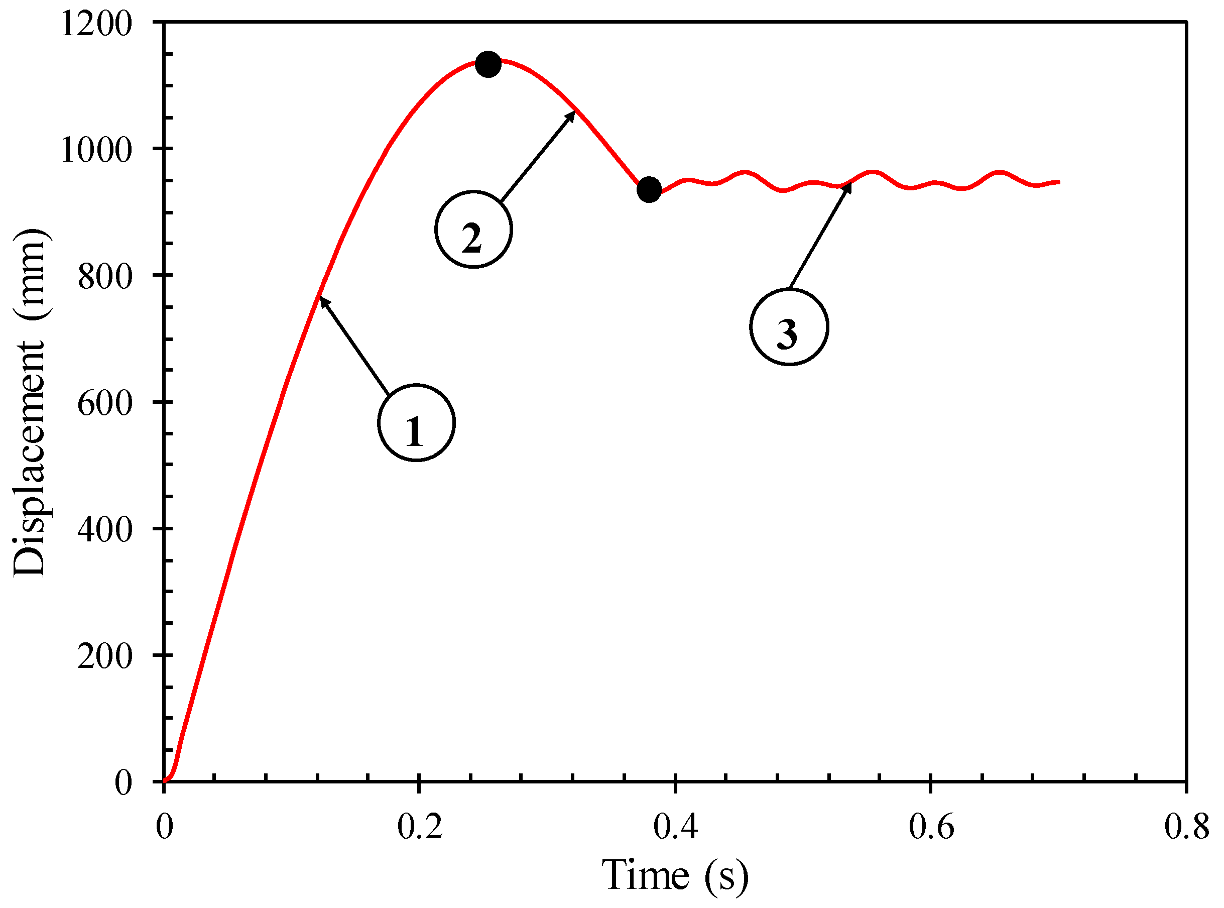
- The energy to be dissipated will result in larger deformations for larger impact velocities. When the impact velocities increase larger than 8 m/s, the increase in stiffness due to the strain rate effect is clear. When the impact velocity increases further, the resistance of the ring-stiffened cylinder against collision decreases due to the tripping of ring-stiffeners near the impact area.
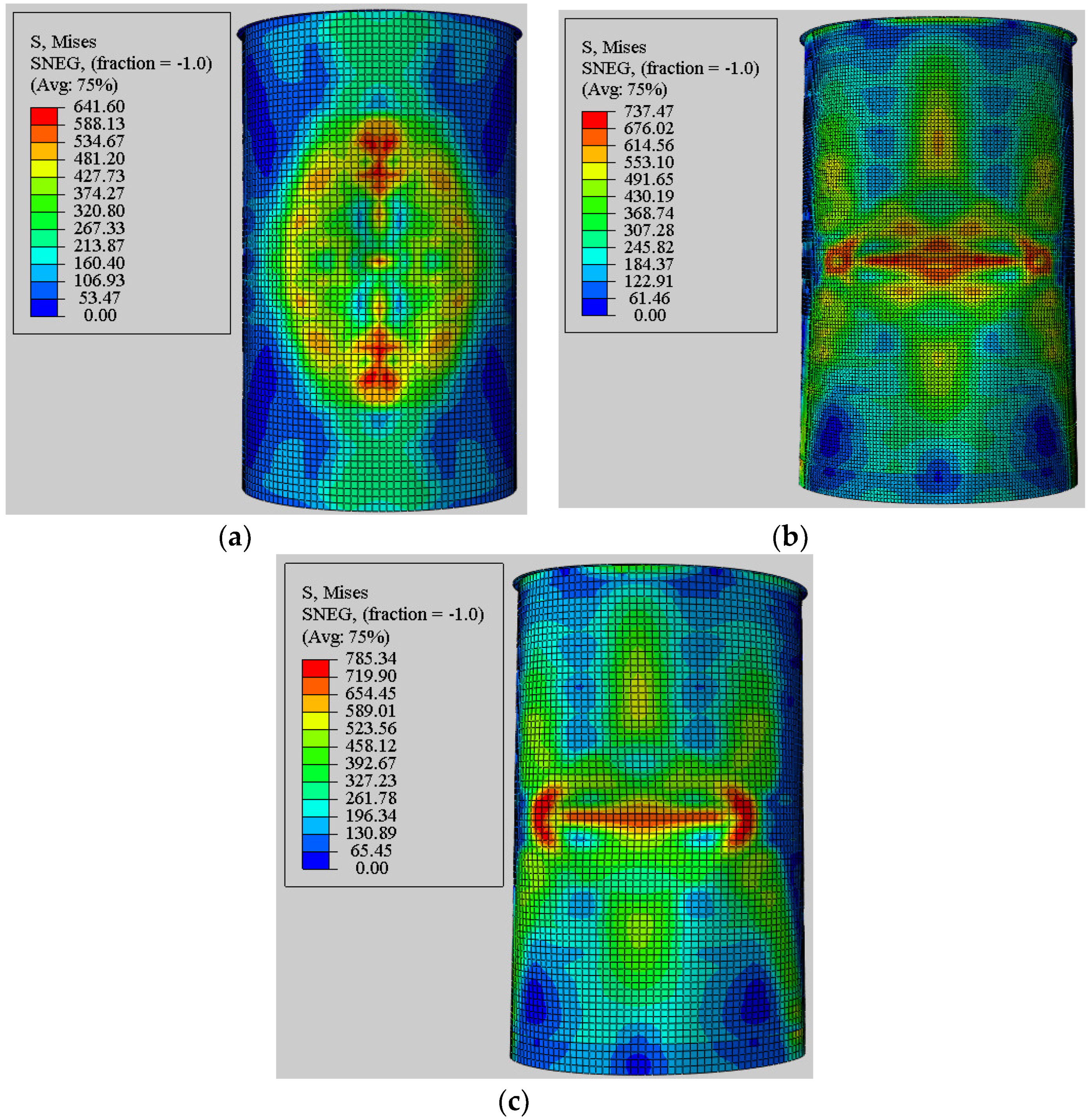
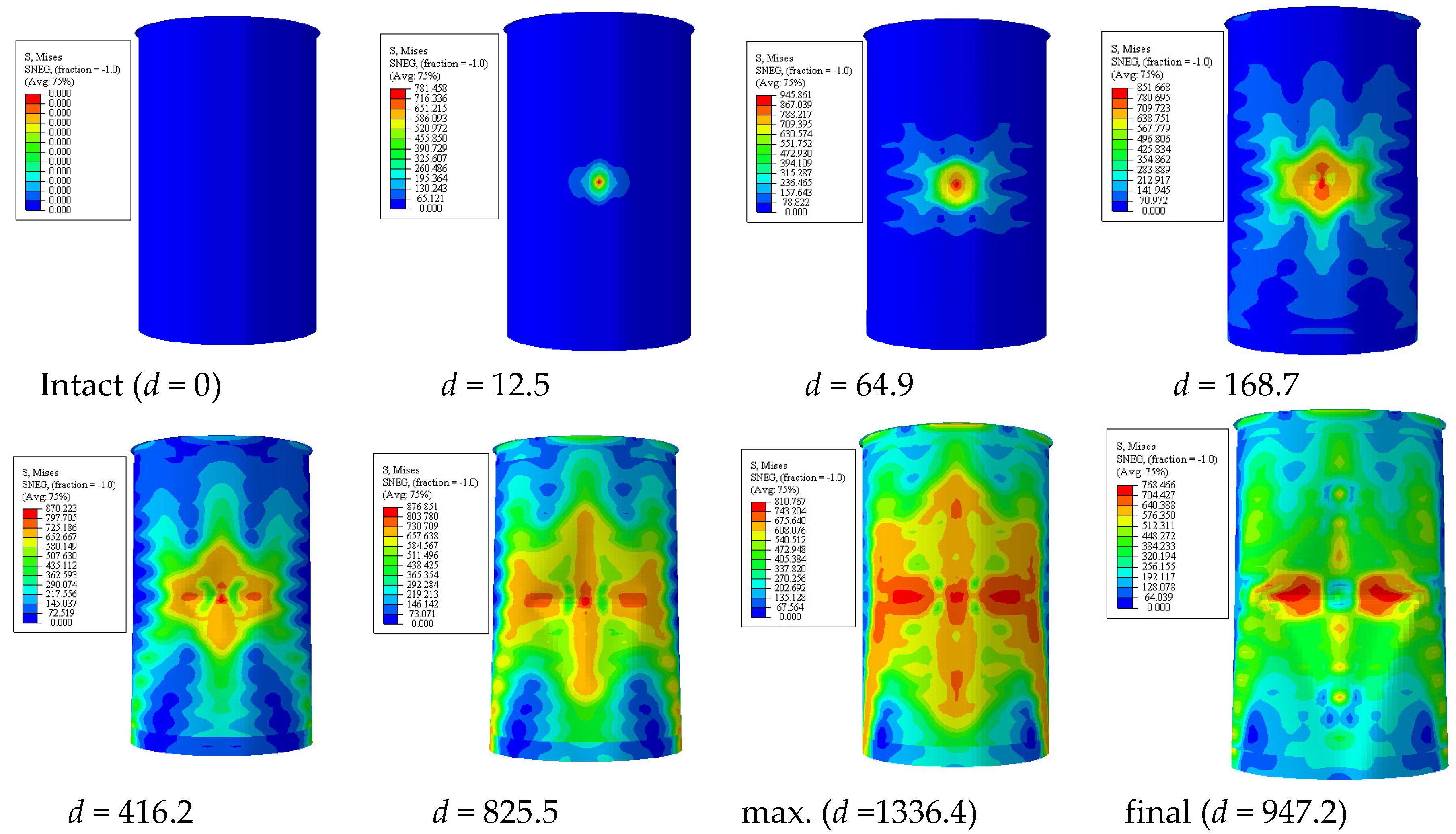
- The extent of local denting damage of the stiffened cylinder was strongly dependent on the impact locations. The permanent dent depth of the unstiffened cylinder approximately doubled in the ring-stiffened cylinder. It was also significantly reduced with each location in the longitudinal direction of the stiffened cylinder. The maximum permanent dent depth almost occurred at the mid-length of the cylinder, and it decreased gradually to the endplate at the boundary conditions because of the membrane stretching of the upper surface of the cylinder shell.
- When considering the effect of the striker header shape, the most severe case is a hemispherical indenter, which resembles highly localized point loading. The resistance of the ring-stiffened cylinder against collision when the load is applied with a hemispherical indenter type was lower than that of the knife-edge and rectangular indenter types by 19% and 32%, respectively. For the stringer-stiffened cylinder, the resistance of cylinder when the load is applied through a hemispherical indenter is much lower than that of the knife-edge and rectangular indenter types by 26% and 37%, respectively.
Author Contributions
Funding
Conflicts of Interest
References
- Det Norske Veritas. Accident statistics for fixed offshore units on the UK Continental Shelf (1980–2005): Research Report RR566. In HSE Books; HSE: Sudbury, Suffolk, 2007. [Google Scholar]
- Cerik, B.C.; Shin, H.; Cho, S.-R. On the resistance of steel ring-stiffened cylinders subjected to low-velocity mass impact. Int. J. Impact Eng. 2015, 84, 108–123. [Google Scholar] [CrossRef]
- Ghanbari-Ghazijahani, T.; Jiao, H.; Holloway, D. Experimental study on damaged cylindrical shells under compression. Thin Walled Struct. 2014, 80, 13–21. [Google Scholar] [CrossRef]
- Ghanbari-Ghazijahani, T.; Jiao, H.; Holloway, D. Experiments on dented cylindrical shells under peripheral pressure. Thin Walled Struct. 2014, 84, 50–58. [Google Scholar] [CrossRef]
- Ghanbari-Ghazijahani, T.; Jiao, H.; Holloway, D. Experiments on Dented Steel Tubes under Bending. Adv. Struct. Eng. 2015, 18, 1807–1817. [Google Scholar] [CrossRef]
- Ghanbari-Ghazijahani, T.; Jiao, H.; Holloway, D. Experiments on locally dented conical shells under axial compression. Steel Compos. Struct. 2015, 19, 1355–1367. [Google Scholar] [CrossRef]
- Do, Q.T.; Muttaqie, T.; Shin, H.; Cho, S.-R. Dynamic lateral mass impact on steel stringer-stiffened cylinders. Int. J. Impact Eng. 2018, 116, 105–126. [Google Scholar] [CrossRef]
- Do, Q.T.; Muttaqie, T.; Park, S.-H.; Shin, H.; Cho, S.-R. Ultimate strength of intact and dented steel stringer-stiffened cylinders under hydrostatic pressure. Thin Walled Struct. 2018, 132, 442–460. [Google Scholar] [CrossRef]
- Do, Q.T.; Muttaqie, T.; Park, S.-H.; Shin, H.; Cho, S.-R. Predicting the collision damage of steel ring-stiffened cylinders and their residual strength under hydrostatic pressure. Ocean Eng. 2018, 169, 326–343. [Google Scholar] [CrossRef]
- Wierzbicki, T.; Suh, M. Indentation of tubes under combined loading. Int. J. Mech. Sci. 1988, 30, 229–248. [Google Scholar] [CrossRef]
- Wierzbicki, T.; Fatt, M.S.H. Impact response of a string-on-plastic foundation. Int. J. Impact Eng. 1992, 12, 21–36. [Google Scholar] [CrossRef]
- Wierzbicki, T.; Fatt, M.S.H. Damage assessment of cylinders due to impact and explosive loading. Int. J. Impact Eng. 1993, 13, 215–241. [Google Scholar] [CrossRef]
- Fatt, M.S.H.; Wierzbicki, T. Denting analysis of ring stiffened cylindrical shells. Int. J. Offshore Polar Eng. 1991, 1, 137–145. [Google Scholar]
- Moussouros, M.; Fatt, M.H. Effect of shear on plastic denting of cylinders. Int. J. Mech. Sci. 1995, 37, 355–371. [Google Scholar] [CrossRef]
- Jones, N. The credibility of predictions for structural designs subjected to large dynamic loadings causing inelastic behaviour. Int. J. Impact Eng. 2013, 53, 106–114. [Google Scholar] [CrossRef]
- Cerik, B.C. Ultimate strength of locally damaged steel stiffened cylinders under axial compression. Thin Walled Struct. 2015, 95, 138–151. [Google Scholar] [CrossRef]
- Cho, S.-R.; Muttaqie, T.; Do, Q.T.; Kim, S.; Kim, S.M.; Han, D.-H. Experimental investigations on the failure modes of ring-stiffened cylinders under external hydrostatic pressure. Int. J. Nav. Arch. Ocean Eng. 2018, 10, 711–729. [Google Scholar] [CrossRef]
- Cho, S.-R.; Do, Q.T.; Shin, H. Residual strength of damaged ring-stiffened cylinders subjected to external hydrostatic pressure. Mar. Struct. 2017, 56, 186–205. [Google Scholar] [CrossRef]
- Cho, S.-R.; Muttaqie, T.; Do, Q.T.; So, H.Y.; Sohn, J.-M. Ultimate strength formulation considering failure mode interactions of ring-stiffened cylinders subjected to hydrostatic pressure. Ocean Eng. 2018, 161, 242–256. [Google Scholar] [CrossRef]
- Muttaqie, T.; Do, Q.T.; Prabowo, A.R.; Cho, S.R.; Sohn, J.M. Numerical studies of the failure modes of ring-stiffened cylinders under hydrostatic pressure. Struct. Eng. Mech. 2019, 70, 431–443. [Google Scholar] [CrossRef]
- Cho, S.-R.; Muttaqie, T.; Do, Q.T.; Park, S.H.; Kim, S.M.; So, H.Y.; Sohn, J.M. Experimental study on ultimate strength of steel-welded ring-stiffened conical shell under external hydrostatic pressure. Mar. Struct. 2019, 67, 102634. [Google Scholar] [CrossRef]
- Prabowo, A.R.; Putranto, T.; Sohn, J.M. Simulation of the Behavior of a Ship Hull under Grounding: Effect of Applied Element Size on Structural Crashworthiness. J. Mar. Sci. Eng. 2019, 7, 270. [Google Scholar] [CrossRef]
- Rathinam, N.; Prabu, B. Numerical study on influence of dent parameters on critical buckling pressure of thin cylindrical shell subjected to uniform lateral pressure. Thin Walled Struct. 2015, 88, 1–15. [Google Scholar] [CrossRef]
- Cerik, B.C.; Ringsberg, J.W.; Choung, J. Revisiting MARSTRUCT benchmark study on side-shell collision with a combined localized necking and stress-state dependent ductile fracture model. Ocean Eng. 2019, 187, 106173. [Google Scholar] [CrossRef]
- Cerik, B.C. Damage assessment of marine grade aluminium alloy-plated structures due to air blast and explosive loads. Thin Walled Struct. 2017, 110, 123–132. [Google Scholar] [CrossRef]
- Cerik, B.C.; Lee, K.; Park, S.-J.; Choung, J. Simulation of ship collision and grounding damage using Hosford-Coulomb fracture model for shell elements. Ocean Eng. 2019, 173, 415–432. [Google Scholar] [CrossRef]
- Prabowo, A.R.; Bae, D.M.; Sohn, J.M.; Zakki, A.; Cao, B.; Cho, J.H. Effects of the rebounding of a striking ship on structural crashworthiness during ship-ship collision. Thin Walled Struct. 2017, 115, 225–239. [Google Scholar] [CrossRef]
- Zhang, S.; Pedersen, P.T. A method for ship collision damage and energy absorption analysis and its validation. Ships Offshore Struct. 2016, 12, S11–S20. [Google Scholar] [CrossRef]
- Liu, B.; Villavicencio, R.; Zhang, S.; Soares, C.G. Assessment of external dynamics and internal mechanics in ship collisions. Ocean Eng. 2017, 141, 326–336. [Google Scholar] [CrossRef]
- Hong, L.; Amdahl, J. Crushing resistance of web girders in ship collision and grounding. Mar. Struct. 2008, 21, 374–401. [Google Scholar] [CrossRef]
- Storheim, M.; Amdahl, J.; Martens, I. On the accuracy of fracture estimation in collision analysis of ship and offshore structures. Mar. Struct. 2015, 44, 254–287. [Google Scholar] [CrossRef]
- Zhang, S.; Villavicencio, R.; Zhu, L.; Pedersen, P.T. Ship collision damage assessment and validation with experiments and numerical simulations. Mar. Struct. 2019, 63, 239–256. [Google Scholar] [CrossRef]
- Cowper, G.R.; Symonds, P.S. Strain-hardening and strain-rate effects in the impact loading of cantilever beams. In Technical Report, No. 28; Division of Applied Mathematics, Brown University: Providence, RI, USA, 1957. [Google Scholar]
- Lee, H.J.; Kim, S.B. A study on application of material properties in ship collision analysis. In Proceedings of the Annual Autumn Conference of the Social of Naval Architecture of Korea, Jeju, Korea, 5 November 2007. [Google Scholar]
- Cho, S.R.; Choi, S.; Son, S. Dynamic material properties of marine steels under impact loadings. In Proceedings of the 2015 World Congress on Advances in Structural Engineering and Mechanics, Incheon, Korea, 21 August 2015. [Google Scholar]
- Moulas, D.; Shafiee, M.; Mehmanparast, A. Damage analysis of ship collisions with offshore wind turbine foundations. Ocean Eng. 2017, 143, 149–162. [Google Scholar] [CrossRef]
- ABS. Guide for Buckling and Ultimate Strength Assessment for Offshore Structures; American Bureau of Shipping: Houston, TX, USA, 2018. [Google Scholar]
- API. Bulletin on Stability Design of Cylindrical Shells. In Policy; American Petroleum Institute: Washington, DC, USA, 2003. [Google Scholar]
- BSI. PD 5500: Specification for Unfired Fusion Welded Pressure Vessels; British Standard Institution: London, UK, 2009. [Google Scholar]


| Model | RS-C-1 | RS-C-2 | RS-C-3 | RS-C-4 | SS-C-1 | SS-C-2 |
|---|---|---|---|---|---|---|
| Radius (mm), R | 400 | 400 | 550 | 550 | 550 | 550 |
| Thickness (mm), t | 3.96 | 3.95 | 4.97 | 4.94 | 2.98 | 2.97 |
| Total length (mm), L | 1060 | 1060 | 1060 | 1060 | 1060 | 1060 |
| Ring-stiffener spacing (mm), l | 200 | 200 | 150 | 150 | 600 | 600 |
| Number of rings, nr | 6 | 6 | 8 | 8 | 2 | 2 |
| Number of stringers, nr | - | - | - | - | 20 | 20 |
| Ring-stiffener web height (mm), hrw | 35.0 | 35.0 | 40.0 | 40.0 | 200 | 200 |
| Ring-stiffener web thickness (mm), trw | 3.94 | 4.0 | 5.81 | 5.81 | 4.90 | 4.92 |
| Stringer-stiffener web height, hsw | - | - | - | - | 65.0 | 65.0 |
| Stringer-stiffener web thickness (mm), tsw | - | - | - | - | 4.98 | 4.87 |
| Ring-stiffener flange width (mm), brf | - | - | - | - | 50.0 | 50.0 |
| Ring-stiffener flange thickness (mm), trf | - | - | - | - | 4.89 | 4.88 |
| Model | RS-C-1 | RS-C-2 | RS-C-3 | RS-C-4 | SS-C-1 | SS-C-2 |
|---|---|---|---|---|---|---|
| Yield strength (MPa), σY | 302.2 | 309 | 274.9 | 274.9 | 335.9 | 335.9 |
| Ultimate strength (MPa), σT | 396.2 | 397.3 | 370.5 | 370.5 | 417.0 | 417.0 |
| Elasticity modulus (GPa), E | 206.0 | 200.0 | 202.4 | 202.4 | 210.0 | 210.0 |
| Hardening start strain, εHS | 0.0227 | 0.0224 | 0.0145 | 0.0145 | 0.0223 | 0.0223 |
| Ultimate tensile strain, εT | 0.196 | 0.194 | 0.234 | 0.234 | 0.1727 | 0.1727 |
| Fracture strain, εF | 0.376 | 0.366 | 0.427 | 0.427 | 0.3811 | 0.3811 |
| Model | RS-C-1 | RS-C-2 | RS-C-3 | RS-C-4 | SS-C-1 | SS-C-2 |
|---|---|---|---|---|---|---|
| Drop height (mm) | 1600 | 1200 | 1200 | 1600 | 1600 | 1580 |
| Collision velocity (m/s) | 5.602 | 4.852 | 4.852 | 5.602 | 5.600 | 5.570 |
| Striker mass (kg) | 295 | 295 | 500 | 500 | 500 | 600 |
| Kinetic energy (J) | 4629 | 3472 | 5249 | 7846 | 7848 | 9300 |
| Model | SS-C-1 | SS-C-2 | RS-C-1 | RS-C-2 | RS-C-3 | RS-C-4 |
|---|---|---|---|---|---|---|
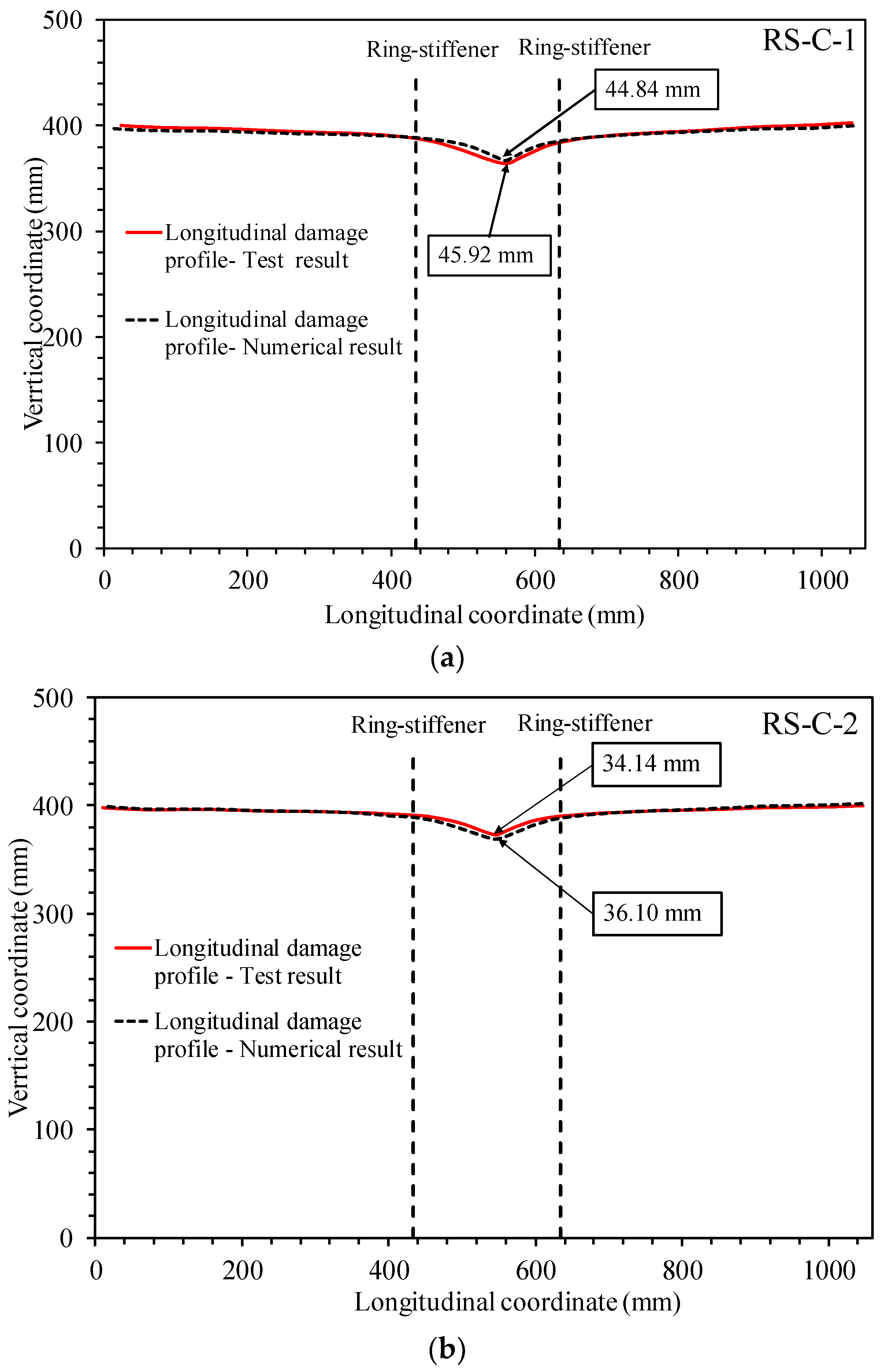
| Test result, d (mm) | 36.80 | 43.20 | 45.92 | 34.14 | 35.52 | 47.35 |
| FEA result, d (mm) | 38.40 | 44.96 | 44.84 | 36.10 | 37.69 | 49.52 |
| Bias (FEA/Test), Xm | 1.043 | 1.041 | 0.976 | 1.057 | 1.061 | 1.046 |
| Mean | 1.038 | |||||
| COV (%) | 2.98 | |||||
| Property | Symbol | Value |
|---|---|---|
| Cylinder radius (mm) | R | 3175 |
| Shell thickness (mm) | t | 20 |
| Ring-stiffener spacing (mm) | Ls | 840.7 |
| Total cylinder length (mm) | L | 10,500 |
| Number of ring-stiffeners | nr | 12 |
| Ring-stiffener web height (mm) | hrw | 95.2 |
| Ring-stiffener web thickness (mm) | trw | 11 |
| Ring-stiffener flange width (mm) | brf | 76.2 |
| Ring-stiffener flange thickness (mm) | trf | 11 |
| Yield strength (MPa) | σY | 645 |
| Young’s modulus (GPa) | E | 206 |
| R/t | 159 |
| Ship Model Used in Simulations |  Bulk Carrier ship |  Utility vessel [36] |  Offshore accommodation barge [36] |
| Overall length (m) | 76.0 | 65.0 | 71.0 |
| Breadth (m) | 16.0 | 14.4 | 20.0 |
| Depth (m) | 5.5 | 6.0 | 6.0 |
| Draft (design) (m) | 4.2 | 4.0 | 3.5 |
| Deadweight (ton) | 4000 | 4000 | 4000 |
| Unit | RS-1 | RS-2 | RS-3 | RS-4 | RS-5 | RS-6 | RS-7 | RS-8 | RS-9 | RS-10 | |
|---|---|---|---|---|---|---|---|---|---|---|---|
| R | mm | 3100 | 3023 | 3175 | 3100 | 2550 | 5150 | 2500 | 3500 | 550 | 3180 |
| t | mm | 30 | 25 | 20 | 23 | 26.2 | 30 | 15 | 12 | 4.97 | 7.0 |
| L | mm | 12,600 | 15,240 | 10,500 | 10,320 | 14,850 | 16,250 | 11,250 | 7500 | 1060 | 6650 |
| Ls | mm | 430 | 3048 | 840.7 | 430 | 450 | 650 | 750 | 400 | 150 | 350 |
| σY | MPa | 645 | 754 | 645 | 645 | 827 | 645 | 380 | 276 | 275 | 345 |
| E | GPa | 206 | 206 | 206 | 206 | 210 | 206 | 205 | 199 | 202 | 199 |
| nr | - | 29 | 5 | 12 | 24 | 33 | 25 | 15 | 19 | 7 | 19 |
| hrw | mm | 210 | 214 | 95.2 | 180 | 178 | 262 | 190 | 255 | 40 | 120 |
| trw | mm | 19 | 15 | 11 | 13 | 26 | 16.5 | 20 | 11.5 | 6 | 19 |
| brf | mm | 155 | 280 | 76.2 | 90 | 102 | 231 | 120 | 76.2 | 0 | 90 |
| trf | mm | 19 | 17 | 11 | 23 | 14 | 24 | 20 | 11.5 | 0 | 17 |
| R/t | - | 103 | 121 | 159 | 135 | 97 | 172 | 167 | 292 | 111 | 454 |
| Unit | SS-1 | SS-2 | SS-3 | SS-4 | SS-5 | SS-6 | SS-7 | SS-8 | |
|---|---|---|---|---|---|---|---|---|---|
| R | mm | 3100 | 3025 | 2500 | 4200 | 3025 | 13,320 | 8880 | 9500 |
| t | mm | 28 | 19.0 | 15 | 20.0 | 12.0 | 41.5 | 25.0 | 20.0 |
| L | mm | 12,500 | 10,240 | 11,250 | 10,500 | 10,240 | 17,500.0 | 6600 | 26,000 |
| Ls | mm | 3000 | 2048.0 | 2250 | 3500 | 2048 | 3500.0 | 2200 | 3200 |
| nr | - | 4.0 | 4.0 | 4.0 | 2.0 | 4.0 | 4.0 | 2.0 | 8.0 |
| hrw | mm | 210.0 | 214.0 | 190.00 | 700 | 214.0 | 787.5 | 525 | 650 |
| trw | mm | 25.0 | 20.0 | 20 | 12.0 | 15.0 | 37.5 | 25.0 | 20.0 |
| wrf | mm | 250 | 200.0 | 150 | 300 | 200 | 450.0 | 300 | 300 |
| trf | mm | 25 | 20.0 | 20 | 16.0 | 15.0 | 45.0 | 30.0 | 20.0 |
| ns | - | 20 | 18.0 | 20 | 36 | 18.0 | 36.0 | 60.0 | 18.0 |
| hsw | mm | 130.0 | 160.0 | 150 | 250.0 | 160.0 | 450.0 | 300 | 400 |
| tsw | mm | 25.0 | 15.0 | 20 | 12.0 | 11.5 | 37.5 | 15.0 | 20.0 |
| wsf | mm | 80.0 | 100.0 | 100 | 90.0 | 100.0 | 285.0 | 190.0 | 200 |
| tsf | mm | 25 | 15.0 | 20 | 12.0 | 11.5 | 45.0 | 19.0 | 20.0 |
| σY | MPa | 450 | 276.0 | 380 | 355 | 276 | 345.0 | 345 | 645 |
| E | GPa | 210,000 | 205,000 | 206,000 | 206 | 205,000 | 206,000 | 200,000 | 207,000 |
| R/t | - | 111 | 159 | 167 | 210 | 263 | 321 | 355 | 475 |
| Model | SS-C-1 | SS-C-2 | RS-C-1 | RS-C-2 | RS-C-3 | RS-C-4 |
|---|---|---|---|---|---|---|
| Test result, d (mm) | 36.80 | 43.20 | 45.92 | 34.14 | 35.52 | 47.35 |
| Proposed formulation, d (mm) | 39.77 | 44.67 | 48.53 | 33.95 | 36.89 | 49.07 |
| Bias (Prop. Formulation/Test), Xm | 1.081 | 1.034 | 1.057 | 0.994 | 1.039 | 1.036 |
| Mean of Xm | 1.040 | |||||
| COV (%) | 2.74 | |||||
© 2020 by the authors. Licensee MDPI, Basel, Switzerland. This article is an open access article distributed under the terms and conditions of the Creative Commons Attribution (CC BY) license (http://creativecommons.org/licenses/by/4.0/).
Share and Cite
Do, Q.T.; Huynh, V.V.; Vu, M.T.; Tuyen, V.V.; Pham-Thanh, N.; Tra, T.H.; Vu, Q.-V.; Cho, S.-R. A New Formulation for Predicting the Collision Damage of Steel Stiffened Cylinders Subjected to Dynamic Lateral Mass Impact. Appl. Sci. 2020, 10, 3856. https://doi.org/10.3390/app10113856
Do QT, Huynh VV, Vu MT, Tuyen VV, Pham-Thanh N, Tra TH, Vu Q-V, Cho S-R. A New Formulation for Predicting the Collision Damage of Steel Stiffened Cylinders Subjected to Dynamic Lateral Mass Impact. Applied Sciences. 2020; 10(11):3856. https://doi.org/10.3390/app10113856
Chicago/Turabian StyleDo, Quang Thang, Van Vu Huynh, Mai The Vu, Vu Van Tuyen, Nhut Pham-Thanh, Tran Hung Tra, Quang-Viet Vu, and Sang-Rai Cho. 2020. "A New Formulation for Predicting the Collision Damage of Steel Stiffened Cylinders Subjected to Dynamic Lateral Mass Impact" Applied Sciences 10, no. 11: 3856. https://doi.org/10.3390/app10113856
APA StyleDo, Q. T., Huynh, V. V., Vu, M. T., Tuyen, V. V., Pham-Thanh, N., Tra, T. H., Vu, Q.-V., & Cho, S.-R. (2020). A New Formulation for Predicting the Collision Damage of Steel Stiffened Cylinders Subjected to Dynamic Lateral Mass Impact. Applied Sciences, 10(11), 3856. https://doi.org/10.3390/app10113856