Article

Cathodic Protection Using Aluminum Metal in Chloride Molten Salts as Thermal Energy Storage Material in Concentrating Solar Power Plants

by
Angel G. Fernández
* and
Luisa F. Cabeza
GREiA Research Group, Universitat de Lleida, Pere de Cabrera s/n, 25001 Lleida, Spain
*
Author to whom correspondence should be addressed.
Appl. Sci. 2020, 10(11), 3724; https://doi.org/10.3390/app10113724
Submission received: 5 May 2020 / Revised: 21 May 2020 / Accepted: 25 May 2020 / Published: 27 May 2020
(This article belongs to the Special Issue TES Materials for High Temperature Applications)

Abstract

:

Featured Application

Concentrated solar power technology, corrosion mitigation strategy on TES materials at high temperature.

Abstract

The new generation of concentrated solar power (CSP) plants to be developed presents a great challenge related to the increase in maximum operating temperature since molten salt CSP technologies require alternative salt chemistries such as chloride. The cathodic protection strategy involves the addition of a sacrificial metal to prevent corrosion of the alloy tested as container material in a CSP plant. In this paper, aluminum (Al) metal was analyzed as a corrosion inhibitor in OCT and HR224 alloys, obtaining corrosion rates of 4.37 and 0.27 mm/y, respectively. It has been confirmed that the use of Al metal can reduce the anodic current which is directly related to the corrosion rate. The formation of protective alumina scales (Al2O3) was assessed by scanning electron microscopy (SEM) and X-ray diffraction (XRD), confirming the corrosion model results from electrochemical impedance spectroscopy monitoring tests.

1. Introduction

In the last years, an opportunity has been identified to obtain higher power-generation efficiencies in concentrated solar power (CSP) plants using supercritical CO2 (sCO2) Brayton power cycle. The CSP technology needs to integrate high-temperature storage materials able to work in the range of 550 °C to 750 °C [1]. For this purpose, the selection of high-temperature molten salt chemistry is needed and due to their low cost and high decomposition temperature, molten chlorides have been proposed as a feasible option. However, these molten salts introduce important drawbacks related to their very corrosive nature on typical containment materials.
According to Mehos et al. [1], the cost for the chloride salt system is dominated by the cost of the material to contain the storage material hot salt tank (70%) due to the expense and size of this tank. In this case, the cold tank would be built using austenitic stainless steel since the operating temperature for this tank would be 520 °C. This cost simulation was carried out using Haynes 230 alloy in the hot tank and AISI 347 in the cold storage tank.
It is clear that a corrosion mitigation strategy is necessary to use low-cost alloys in the CSP storage tanks. With this aim, cathodic protection has been proposed in the literature [2,3] to mitigate corrosion of alloys in molten salts, using a sacrificial metal that more easily “corrodes” is used to prevent corrosion of the alloy or its components. It was shown that the major corrosion mechanism of alloys in molten salts is the selective oxidation of chromium [4]. It usually occurs at the grain boundaries [5,6]. Such experimental observation is confirmed by electrochemical impedance spectroscopy (EIS) measurement showing a phase angle no higher than 45 °C which indicates that the corrosion of alloys in molten salts has fast reaction kinetics and it is usually mass-transfer limited. It was shown that Cr3+ is less thermodynamically stable than the cations in the molten MgCl2-KCl mixture (i.e., Mg2+ and K+) such that Cr in the alloy will not react with Mg2+ and/or K+ to form Cr3+ [7,8]. However, Cr2+ is more thermodynamically stable, which means that Cr in the alloy tends to react, forming Cr2+. The oxidation of Cr to form Cr2+ accounts for the major corrosion mechanism of Cr-containing alloys.
In this case, some authors [2,9] have proposed the addition of Mg metal into the chloride molten salt mixture, since the reduction potential of the alloy components can be modified, obtaining that the main anodic current belongs to the oxidation of this metal, avoiding the oxidation of the target alloy.
The corrosion rates of Haynes 230, Haynes 163, and Incoloy 800H were experimentally obtained as a function of wt.% of Mg added (from 0% to 1.15%). In all three cases, the corrosion rates were significantly reduced and the results from experiments and modeling agreed very well. Specifically, the corrosion rate of Haynes 230 at 850 °C was reduced to less than 15 μm/y with 1.15 wt.% Mg addition compared to the baseline test without Mg addition. A key effect of this behavior is the formation of magnesium oxide (MgO) on the cathode, which can be related to the electrode passivation, obtaining a lower electrolysis current [2].
Corrosion products formed in Mg metal can introduce a new set of impurities in the molten salt, affecting the thermal properties of this material so the proposal of new cathodic elements needs to be addressed.
In this research, a first approach of a new cathodic element (Al metal) is proposed in order to mitigate corrosion. Al metal presents a reduction potential voltage (Al→Al3+) of −1.662V, acting as an anode in contact with the common elements present in superalloys Ni→Ni2+ (1.59 V) or Cr→Cr2+ (1.33 V). This element can also reduce the impurities formed in the chloride salts and maintain the thermal properties required for TES materials with a lower corrosion rate potential.

2. Methodology

A ternary chloride molten salt composed of 20.4 wt.% KCl + 55.1 wt.% MgCl2 + 24.5 wt.% NaCl (Sigma Aldrich 99%, Missouri, USA) was selected as thermal energy storage material. Experimental tests were carried out at 720 °C under inert atmosphere (N2).
The salts were dried and purified following stepwise heating for the purification process, previously reported in [10], was carried out. After this process, the electrodes were immersed in the chloride salt at 720 °C, including 10 wt.% Al metal (100% bare Al metal, Randrade, Spain).
The electrochemical impedance spectroscopy (EIS) cell was composed of a working electrode (WE, with the alloy to be tested), a quasi-reference (RE, platinum wire), and a counter (CE, platinum mesh) electrode. For the corrosion test, the electrodes were introduced in the molten salt, acting as electrolyte, and the electrochemical parameters were measured using the EIS equipment (Gamry 1010E, Gamry, Philadelphia, PA, USA). The experimental set up is shown in Figure 1.
EIS tests were carried out at 3, 5, 24, and 50 h of immersion in order to monitor the corrosion mechanism and the frequency range for EIS tests was between 105 and 0.01 Hz. Finally, linear polarization resistance (LPR) tests were performed from a potential of −0.6 to 0.4 V were carried out in two different alloys, with a chemical composition shown in Table 1.
After the corrosion tests, the samples were cleaned with hot distilled water and dried. For SEM characterization, a polymer resin was prepared by mixing HardRock 554 resin (Phase, Firenze, Italy) and catalyst, in a 2:1 proportion. After the resin cured, the samples were ground and polished using different granulometry of SiC abrasive papers, using diamond power (1 micron) to polish the samples. Quanta 200 FEG SEM operated in high vacuum mode at 20 kV equipped with a backscattered electron detector was used for the microstructural analysis, including an EDX analyzer with a recommended working distance of around 10 mm.
For XRD tests, a PANalytical X’Pert PRO powder diffractometer (Perkin-Elmer, Waltham, MA, USA) was used with a θ/2θ incidence from 10 to 100°.
Using electrochemical impedance spectroscopy (EIS), different authors [11,12,13] have proposed equivalent circuits corresponding to the main corrosion mechanisms in molten salts at high temperatures, obtaining protective, porous, or localized corrosion models.
For linear polarization resistance tests, it is important to quantify the polarization resistance, R p , related to the potential drop attributed to the molten salt, acting as electrolyte. The corrosion density current   (   i c o r r ) can be obtained using Equation (1):
  i c o r r = B R p  
where B is an electrochemical constant calculated through the anodic and cathodic Tafel slopes by Equation (2):
B = β α · β c 2.3   · ( β α + β c )
The corrosion rate (CR) is given by the Butler–Volmer equation shown in Equation (3)
C R = i c o r r · K ρ a l l o y · Σ ( f i · n i M W i )
where K is a constant with a value of 3272 for C R in mm/y, ρ alloy is the alloy density (g/cm3), f i is the mole fraction of the element i in the alloy, n i is the number of electrons that are transferred in the corrosion process, and M W i is the atomic weight of the alloy tested.

3. Results and Discussion

EIS signals (Nyquist plots) obtained for OCT alloy (Figure 2) were fitted to a protective layer model during the corrosion process at the different testing times. The equivalent circuit element values for this material are shown in Table 2.
R3 represents the molten salt (electrolyte) resistance and R5 is the electrochemical transfer resistance or polarization resistance of the tested material. Q1 is the double layer at the metal/salt interface and Q2 represents the oxide capacitance. The R7 electrochemical parameter is related to the transfer resistance of ions in the scale. In this case, it is important to point out that the electrolyte resistance (R3) decreases during the experimental time, so electronic conductivity may be favored as well as corrosion potential processes.
These results were confirmed by SEM analysis (Figure 3), obtaining a protective layer with Fe–Cr–Ni–Al–O content.
OCT alloy was previously tested [14] for 8 h of immersion in the same chloride molten salt. In this case, no internal oxidation was detected after 50 h using Al metal as cathodic protection.
Results obtained for HR224 alloy (Figure 4) were fitted to a protective corrosion model during all the testing times. Electrochemical parameters obtained for the equivalent circuits are shown in Table 3.
SEM analysis (Figure 5) showed internal oxidation of 28.35 microns of thickness (Figure 5 right) with higher Ni content. This internal oxidation was reported [15] as a potential problem since it can cause mechanical failures during thermal cycles in the CSP plant operation.
The superficial image (Figure 5 left) showed some needle-shaped particles in the alloy surface, with content in aluminum. Similar particles were obtained by Fernandez et al. [16] adding Al2O3 nanoparticles in nitrate molten salts, reporting a higher corrosion resistance behavior due to this protective barrier formed in the alloy/salt interphase.
In order to confirm the corrosion layer composition obtained, XRD analysis was carried out in the materials tested. Protective layers composed of Al2O3 and NiO were obtained for HR224 (Figure 6) and Al2O3 for OCT (Figure 7), confirming the protective mechanism detected by EIS and SEM.
Additionally, slight signals corresponding to Fe3O4 were detected in OCT alloy. Another impurity detected in both alloys was MgO. This impurity must be controlled during the corrosion process since it can form MgClOH, one of the most aggressive impurities present in the chloride molten salt tested [17,18]. In this direction, some researchers [19,20] have applied cyclic voltammetry tests to monitor impurities production as well as to define more specific thermal purification analysis during the melting process to control the evolution of this impurity during the corrosion process.
Corrosion rate results obtained through linear polarization technique after 50 h of immersion are shown in Table 4.
As it was mentioned before, these materials were studied for 8 h of immersion in previous research [15], obtaining a corrosion rate of 7.61 mm/y for OCT alloy and 3.12 mm/y for HR224. In this case, corrosion rates obtained using Al metal as a cathodic protection element showed an important corrosion rate reduction in both elements. The lowest corrosion rate was obtained for HR224 (0.27 mm/y), nevertheless, the internal oxidation detected by SEM (Figure 5), could be a potential issue during thermal cycles, generating mechanic failures, during CSP plant operations and some additional tests will be carried out in future research.

4. Conclusions

A new cathodic protection element to control the corrosive potential in chloride molten salts as a thermal energy storage material for CSP plants was analyzed in the paper. Key conclusions include the following:
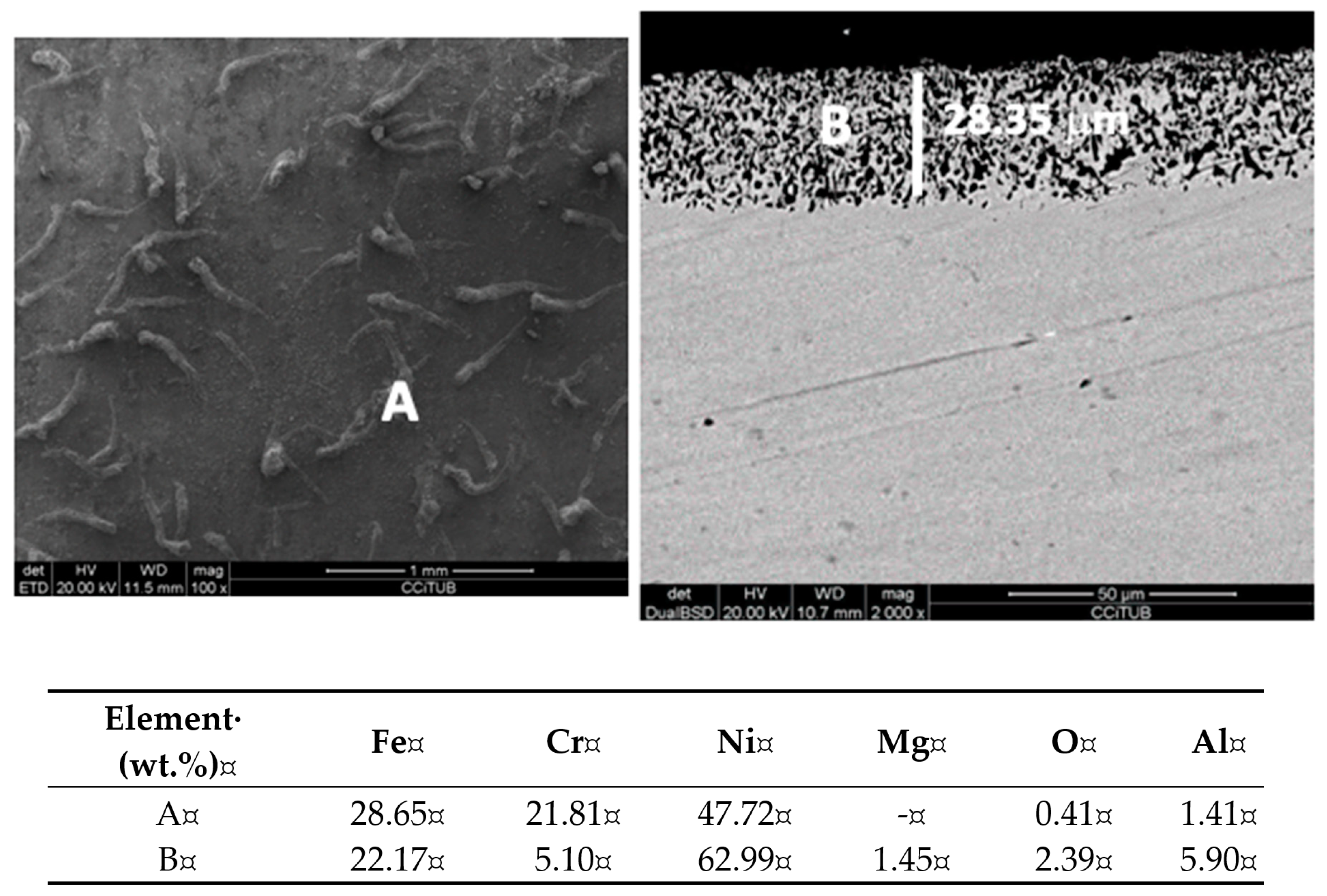
  • By adding Al metal into chloride molten salts (cathodic protection), the reduction potential of the alloy can be controlled. The most thermodynamically stable form of chromium in the alloys tested is hence the metallic chromium, meaning that selective oxidation of chromium in the Cr-containing alloys did not occur.
  • This behavior can be explained by the formation of Al2O3 in the alloy surface which can generate a passivation layer and hence a reduction of the electrolysis current and lower corrosion rates.
This behavior can be a successful starting point to continue with corrosion mitigation strategies focused on cathodic protection using aluminum metal to achieve a CSP plant lifetime of 30 years or longer.

Author Contributions

Conceptualization, A.G.F. and L.F.C.; methodology, A.G.F. and L.F.C.; lab testing, A.G.F.; software, A.G.F.; formal analysis, A.G.F., and L.F.C.; investigation, A.G.F. and L.F.C.; writing—original draft preparation, A.G.F.; writing—review and editing, L.F.C.; supervision, L.F.C.; project administration, A.G.F. and L.F.C.; funding acquisition, A.G.F. and L.F.C. All authors have read and agreed to the published version of the manuscript.

Funding

This project has received funding from the European Union’s Horizon 2020 research and innovation program under the Marie Sklodowska-Curie grant No 712949 (TECNIOspring PLUS) and from the Agency for Business Competitiveness of the Government of Catalonia. This work was partially funded by the Ministerio de Ciencia, Innovación y Universidades de España (RTI2018-093849-B-C31 - MCIU/AEI/FEDER, UE). This work was partially funded by the Ministerio de Ciencia, Innovación y Universidades - AgencHia Estatal de Investigación (AEI, RED2018-102431-T). This work is partially supported by ICREA under the ICREA Academia program.

Acknowledgments

The authors would like to thank the Catalan Government for the quality accreditation given to their research group (GREiA 2017 SGR 1537). GREiA is certified agent TECNIO in the category of technology developers from the Government of Catalonia.

Conflicts of Interest

The authors declare no conflicts of interest. The funders had no role in the design of the study; in the collection, analyses, or interpretation of data; in the writing of the manuscript, or in the decision to publish the results.

References

  1. Mehos, M.; Turchi, C.; Vidal, J.; Wagner, M.; Ma, Z.; Ho, C.; Kolb, W.; Andraka, C.; Kruizenga, A. Concentrating Solar Power Gen3 Demonstration Roadmap; Technical Report; NREL: Golden, CO, USA, 2017. [Google Scholar]
  2. Ding, W.; Gomez-Vidal, J.; Bonk, A.; Bauer, T. Molten chloride salts for next generation CSP plants: Electrolytical salt purification for reducing corrosive impurity level. Sol. Energy Mater. Sol. Cells 2019, 199, 8–15. [Google Scholar] [CrossRef]
  3. Mehrabadi, B.A.T.; Weidner, J.W.; Garcia-Diaz, B.; Martinez-Rodriguez, M.; Olson, L.; Shimpalee, S. Modeling the Effect of Cathodic Protection on Superalloys Inside High Temperature Molten Salt Systems. J. Electrochem. Soc. 2017, 164, C171–C179. [Google Scholar] [CrossRef]
  4. Wang, Y.; Liu, H.; Yu, G.; Hou, J.; Zeng, C. Electrochemical Study of the Corrosion of a Ni-based Alloy GH3535 in Molten (Li,Na,K)F at 700°C. J. Fluor. Chem. 2015, 178, 14–22. [Google Scholar] [CrossRef]
  5. Wang, Y.; Liu, H.; Zeng, C. Galvanic Corrosion of Pure Metals in Molten Fluorides. J. Fluor. Chem. 2014, 165, 1–6. [Google Scholar] [CrossRef]
  6. Ding, W.; Shi, H.; Xiu, Y.; Bonk, A.; Weisenburger, A.; Jianu, A.; Bauer, T. Molten chloride salts for next generation concentrated solar power plants: Mitigation strategies against corrosion of structural materials. Sol. Energy Mater. Sol. Cells 2018, 184, 22–30. [Google Scholar] [CrossRef]
  7. Krumpelt, M.; Fischer, J.; Johnson, I. The Reaction of Magnesium Metal with Magnesium Chloride. J. Phys. Chem. 1968, 72, 506–511. [Google Scholar] [CrossRef]
  8. Mehrabadi, B.; Weidner, J.W.; Garcia-Diaz, B.; Martinez-Rodriguez, M.; Olson, L.; Shimpalee, S. Multidimensional Modeling of Nickel Alloy Corrosion inside High Temperature Molten Salt Systems. J. Electrochem. Soc. 2016, 163, C830–C838. [Google Scholar] [CrossRef]
  9. Ding, W.; Bonk, A.; Bauer, T. Corrosion behavior of metallic alloys in molten chloride salts for thermal energy storage in concentrated solar power plants: A review. Front. Chem. Sci. Eng. 2018, 12, 564–576. [Google Scholar] [CrossRef] [Green Version]
  10. Fernandez, A.G.; Cabeza, L.F. Corrosion evaluation of eutectic chloride molten salt for new generation of CSP plants. Part 1: Thermal treatment assessment. J. Energy Storage 2020, 27, 101125. [Google Scholar] [CrossRef]
  11. Kisza, A. The capacitance of the diffuse layer of electric double layer of electrodes in molten salts. Electrochim. Acta 2006, 51, 2315–2321. [Google Scholar] [CrossRef]
  12. Orazem, M.E. An integrated approach to electrochemical impedance spectroscopy. Electrochim. Acta 2008, 53, 7360–7366. [Google Scholar] [CrossRef]
  13. Zeng, C.L.; Wang, W.; Wu, W.T. Electrochemical impedance models for molten salt corrosion. Corros. Sci. 2001, 43, 787–801. [Google Scholar] [CrossRef]
  14. Fernandez, A.G.; Cabeza, L.F. Anodic protection assessment using alumina forming alloys in chloride molten salt for CSP plants. Coatings 2020, 10, 138. [Google Scholar] [CrossRef] [Green Version]
  15. Fernández, A.G.; Cabeza, L.F. Corrosion evaluation of eutectic chloride molten salt for new generation of CSP plants. Part 2: Materials screening performance. J. Energy Storage 2020, 29, 101381. [Google Scholar] [CrossRef]
  16. Fernandez, A.G.; Muñoz-Sanchez, B.; Maestre, J.N. Garcia-Romero, High temperature corrosion behavior on molten nitrate salt based nanofluid for CSP plants. Renew. Energy 2019, 130, 902–909. [Google Scholar] [CrossRef]
  17. Zhao, Y.; Klammer, N.; Gomez-Vidal, J. Purification strategy and effect of impurities on corrosivity of dehydrated carnallite for thermal solar applications. RSC Adv. 2019, 9, 41664–41671. [Google Scholar] [CrossRef] [Green Version]
  18. Klammer, N.; Engtrakul, C.; Zhao, Y.; Wu, Y.; Vidal, J. A method to determine MgO and MgOHCl in chloride molten salts. Anal. Chem. 2020, 92, 3598–3604. [Google Scholar] [CrossRef] [PubMed]
  19. Choi, S.; Orabona, N.E.; Dale, O.R.; Okabe, P.; Inman, C.; Simpson, M.F. Effect of Mg dissolution on cyclic voltammetry and open circuit potentiometry of molten MgCl2–KCl–NaCl candidate heat transfer fluid for concentrating solar power. Sol. Energy Mater. Sol. Cells 2019, 202, 110087. [Google Scholar] [CrossRef]
  20. Ding, W.; Bonk, A.; Gussone, J.; Bauer, T. Electrochemical measurement of corrosive impurities in molten chlorides for thermal energy storage. J. Energy Storage 2020, 15, 408–414. [Google Scholar] [CrossRef]
Figure 1. Electrochemical impedance spectroscopy (EIS) experimental setup test: 1: furnace; 2: reactor; 3: counter electrode, 4: thermocouple, 5: working electrode, 6: quasi-reference electrode, 7: gas inlet, 8: sealed reactor, 9: molten salt, 10: carrier gas (N2), 11: MgO trap; 12: security trap; 13: NaOH [1M] and 14: gas outlet.
Applsci 10 03724 g001
Figure 2. Nyquist plots of OCT immersed chloride molten salt at 3, 5, 24, and 50 h.
Applsci 10 03724 g002
Figure 3. Top view (left) and cross-section; (right) images for OCT immersed in chloride molten salt for 50 h at 720 °C including energy dispersive X-ray (EDX) analysis (A–B).
Applsci 10 03724 g003
Figure 4. Nyquist plots of HR224 immersed in chloride molten salt at 3, 5, 24, and 50 h.
Applsci 10 03724 g004
Figure 5. Top view (left) and cross-section; (right) images for HR224 alloy immersed in chloride molten salt for 50 h at 720 °C including EDX analysis (A–B).
Applsci 10 03724 g005
Figure 6. X-ray diffraction (XRD) obtained in HR224 after 50 h of immersion in chloride molten salt at 720 °C.
Applsci 10 03724 g006
Figure 7. XRD obtained in OCT after 50 h of immersion in chloride molten salt at 720 °C.
Applsci 10 03724 g007
Table 1. Chemical composition of alloys tested.
Alloyswt.%
NbMnCrTiCoMoNiAlFe
OCT3-142--353Balance
HR224-0.5200.320.5473.827.5
Table 2. Electrochemical parameters obtained for electrochemical impedance spectroscopy (EIS) tests in OCT alloy.
ElementR3 (Ohm)Q1 (F/s)R5 (Ohm)Q2 (F/s)R7 (Ohm)Equivalent Circuit
3 h1.5070.32536.210.18359.45 Applsci 10 03724 i001
5 h1.5610.24315.560.289232.07
24 h0.8530.0070.060.05663.56
50 h0.8550.07932.90.477167.8
Table 3. Electrochemical parameters obtained for EIS tests in HR224 alloy.
ElementR3 (Ohm)Q1 (F/s)R5 (Ohm)Q2 (F/s)R7 (Ohm)Equivalent Circuit
3 h1.7620.2722.390.09837.89 Applsci 10 03724 i002
5 h1.8962.50815.550.07227.39
24 h1.9680.07324.981.53618.04
50 h2.0510.17163.140.1308.101
Table 4. Electrochemical parameters and corrosion rates obtained and linear polarization resistance (LPR) test for OCT and HR224 alloys.
AlloysEcorr (mV)Icorr (mA)βc (mV)βa (mV)A (cm2)CR (mm/y)
OCT−87.322098.62280.8465.64.204.37
HR224−31.16210.62239.7241.36.750.27

