Article

Analysis of Hybrid Vector Beams Generated with a Detuned Q-Plate

by
Julio César Quiceno-Moreno
1,2,
David Marco
1,
María del Mar Sánchez-López
1,3,*,
Efraín Solarte
2 and
Ignacio Moreno
1,4
1
Instituto de Bioingeniería, Universidad Miguel Hernández de Elche, 03202 Elche, Spain
2
Departamento de Física, Universidad del Valle, Cali 760032, Colombia
3
Departamento de Física Aplicada, Universidad Miguel Hernández de Elche, 03202 Elche, Spain
4
Departamento de Ciencia de Materiales, Óptica y Tecnología Electrónica, Universidad Miguel Hernández de Elche, 03202 Elche, Spain
*
Author to whom correspondence should be addressed.
Appl. Sci. 2020, 10(10), 3427; https://doi.org/10.3390/app10103427
Submission received: 7 April 2020 / Revised: 10 May 2020 / Accepted: 11 May 2020 / Published: 15 May 2020
(This article belongs to the Special Issue Ultrafast Vortex Pulses)

Abstract

:

Featured Application

Optical Communications; Snapshot Polarimetry; Micromachining; Particle Manipulation.

Abstract

We use a tunable commercial liquid-crystal device tuned to a quarter-wave retardance to study the generation and dynamics of different types of hybrid vector beams. The standard situation where the q-plate is illuminated by a Gaussian beam is compared with other cases where the input beam is a vortex or a pure vector beam. As a result, standard hybrid vector beams but also petal-like hybrid vector beams are generated. These beams are analyzed in the near field and compared with the far field distribution, where their hybrid nature is observed as a transformation of the intensity and polarization patterns. Analytical calculations and numerical results confirm the experiments. We include an approach that provides an intuitive physical explanation of the polarization patterns in terms of mode superpositions and their transformation upon propagation based on their different Gouy phase. The tunable q-plate device presents worthy advantages, since it allows a compact and efficient generation of pure and hybrid vector beams to study these effects.

1. Introduction

Despite the vast amount of literature devoted to vector beams in the last two decades, they still receive much attention due to their exciting applications [1]. Vector beams are complex structured light fields where the state of polarization is spatially variant across the beam section, giving place to phase and polarization singularities [2]. They have been proposed for a few promising applications in areas involving structured light, such as classical and quantum optical communications, particle manipulation, optical trapping, imaging and materials patterning [3]. In order to increase practical applicability, there is a necessity to develop simple, reliable, and efficient methods to generate different kinds of vector beams.
Pure vector beams are the most common type. They are generated by the superposition of two orthogonal polarizations, typically the circular right (RCP) and left (LCP) polarization states, carrying an azimuthal phase exp ( i θ ) of the same topological charge but opposite sign i.e., R = L . On the contrary, in hybrid vector beams (also named vectorial vortices or vector-vortex beams) different topological charges | R | | L | are encoded onto the orthogonal polarization components. They can be represented in the generalized hybrid-order Poincaré sphere [4]. Various approaches have been followed to generate hybrid vector beams. One general approach is based on spatial light modulators (SLM), since they allow encoding arbitrary topological charges onto each polarization component. This is usually done by means of two SLMs [5,6,7] or by dividing the SLM screen in two halves [8]. While these systems offer great flexibility because they can be reprogrammed with arbitrary functions, they are bulky and introduce losses caused by the SLM pixelated structure. Other recent approaches use patterned polarizers [9], patterned retarders (q-plates) combined with polarization rotation devices [10], metasurfaces that encode a spiral geometric phase [11] or uniaxial crystals with special shapes [12]. Initial works made use of pure geometric phase elements where the retardance was adjusted to create different types of pure and hybrid vector beams [13]. Alternatively, a metamaterial q-plate can be combined with a spiral phase plate made as a refractive element [14] or encoded onto an SLM [15,16]. Recent advances in metamaterial techniques allow encoding arbitrary topological charges onto orthogonal polarization components [17]. These elements are compact and efficient, but their performance is fixed on fabrication and cannot be tuned in real time.
One particularly interesting case of hybrid vector beams are full Poincaré beams [18]. These are hybrid vector beams where the topological charge is zero in one polarization component. Therefore, the entire topological charge is encoded on the orthogonal polarization. As one polarization component does not have a phase singularity, the full Poincaré beam does not exhibit null intensity at the center; instead, the center is circularly polarized. Full Poincaré beams have attracted much interest since they generate in the transversal plane a full set of polarization states located at different spatial coordinates. Therefore, they have been proposed for single-shot polarimetry [19]. Full Poincaré beams have been generated with various techniques such as symmetrically stressed windows [18], interferometric arrangements to superimpose two Laguerre–Gauss modes [20], or by employing one single parallel-aligned liquid-crystal SLM operating in transmission [21] or within a Sagnac interferometer [22].
All these works show the great interest in developing methods to generate vector beams. Methods based on q-plate devices are particularly relevant because they are simple, compact, and efficient, a fact of utmost importance for technological applications. The q-plate device is a geometric phase element consisting of a half-wave retarder where the c-axis makes q turns around the azimuthal orientation θ around a central point. The q value is the topological charge of the singularity appearing at the center point and it is fixed on fabrication [23,24]. Q-plates convert input circularly polarized light into the opposite circular polarization and add a helical phase exp ( ± i 2 q θ ) , where the sign is given by the input polarization helicity. Therefore, they have been widely used to impart and manipulate orbital angular momentum (OAM). In addition, because they couple the spin angular momentum (SAM, associated to circular polarization) to the OAM (associated to the wavefront’s helicity) q-plates are also employed to generate non-separable superpositions of local polarization and wavefront modes, i.e., vector beams. Namely, it is well known that a q-plate converts input homogeneous linear polarization into a cylindrical vector beam.
Typically, q-plates are designed to introduce a retardance of π radians (half-wave retardance) at a given operating wavelength. In this condition they provide maximum conversion efficiency. When made of liquid-crystal materials, the device can incorporate electrodes to tune the retardance [25], thus allowing operation at different wavelengths whilst keeping the maximum conversion efficiency [26]. However, it is also possible to operate at a retardance different than the standard π value. A q-plate with q = 1/2 and π/2 retardance (QW q-plate) was identified to generate a hybrid radially polarized beam when being illuminated with circular polarization [13,27]; the generated beam was in fact a full Poincaré beam of charges R = 0 and L = 2 . This situation was also achieved with a non-tunable commercial q-plate by using an operating wavelength where it exhibits quarter-wave retardance [28]. Furthermore, the implementation of quantum walks and wavepacket dynamics has been reported using such QW q-plates [29].
In this work we use an electrically tunable liquid-crystal commercial q-plate [30]. The purpose of this paper is to review different kinds of hybrid vector beams that can be generated with a q-plate with detuned retardance and provide a comprehensive explanation of their polarization patterns within a simple theoretical approach. We consider different input beams illuminating the device, including input homogenous polarizations, vortex beams, and vector beams. In all cases the output is regarded as a hybrid vector beam consisting of the collinear superposition of different modes in the two circular polarization components. The resulting hybrid vector beam shows more or less complicated structure depending on the input beam illuminating the q-plate. Pure and hybrid vector beams display a similar polarization pattern in the near field, since it depends mostly on the R L difference. However, their propagation dynamics are rather different in the far field. While pure vector beams retain their polarization pattern upon propagation, the Gouy phase difference of the two circular polarization components yields transformations in the polarization pattern of hybrid vector beams in the far field [31,32,33]. Therefore, these different kinds of generated hybrid vector beams are analyzed both in the near field and in the far field, in order to evidence their different propagation dynamics. Their theoretical intensity patterns and polarization maps are compared with the experimental results, bearing good agreement.
The paper is organized as follows: after this introduction, Section 2 briefly recalls the essential aspects of q-plates and vector beams required in this work and describes our experimental system and the tunable commercial q-plate employed [30]. For the sake of clarity, the experimental results and their discussion are divided in two sections. In Section 3, we discuss the results obtained when illuminating the q-plate with a circularly polarized state and with a vortex state, which yield simple hybrid vector beams. In Section 4, hybrid petal-type vector beams are obtained for an input linearly polarized state and for an input radial vector beam. Finally, Section 5 presents the conclusions of the work.

2. Materials and Methods

In this section we review the concept of q-plates and their performance to generate scalar vortex beams and vector beams, as well as the propagation dynamics of such beams. While these aspects can be found separately in different references, we briefly include them here for the sake of completeness and to provide the background necessary to explain the different kinds of beams generated in this work, including standard hybrid beams but also novel hybrid petal-type vector beams.

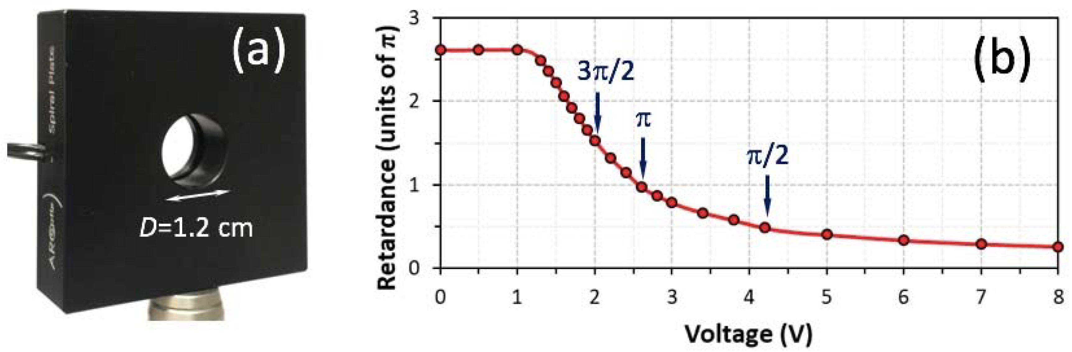
2.1. Q-Plates and Their Polarization Conversion Efficiency

A q-plate is a phase-plate retarder with uniform retardance ϕ whose principal axis follows q times the azimuthal angle θ in the device plane. The q value is an integer or semi-integer, so that the principal axis has a singularity in the plate center, and its sign is positive (negative) for counterclockwise (clockwise) rotation. Q-plates of fixed retardance (static q-plates) are commercially available with q = 1/2 and q = 1, although other values can be ordered on demand [34]. The Jones matrix for a q-plate can be written as [23,24]:
M q ( ϕ ) = cos ( ϕ 2 ) Ι + i sin ( ϕ 2 ) Q q
where I is the identity matrix and Qq is the matrix for a q-plate tuned at π retardance, given by
Q q = ( cos ( 2 q θ ) sin ( 2 q θ ) sin ( 2 q θ ) cos ( 2 q θ ) )
When the q-plate is tuned to π radians (half-wave (HW) q-plate) a full polarization conversion is achieved. This means that a beam of uniform linear polarization entering the q-plate is fully converted into a pure vector beam. For retardance values other than half-wave, the q-plate is detuned and the conversion efficiency decreases. As discussed in [28], the case of quarter-wave (QW) q-plate is of special interest. In this situation, Equation (1) results in M q ( ϕ = ± π / 2 ) = 1 2 ( Ι ± i Q q ) and, if illuminated with an input state Vin, the output beam is given by
V o u t = M q ( ϕ = ± π / 2 ) V i n = 1 2 ( Ι ± i Q q ) V i n
This relation shows that the output is the superposition of the input beam with the one generated by a HW q-plate, with a ± π/2 phase shift in between.
The situation where the HW q-plate is illuminated with circularly polarized light is used to generate vortex beams, since the device reverses the helicity of the light and transfers a spiral phase exp ( ± i 2 q θ ) [23]. This effect can be described approximately as modifications of Laguerre-Gauss (LG) modes. In our work we follow [35,36] for the definition of the LG modes and we only consider modes with radial index p = 0, which are vortex beams of azimuthal index given by:
L G 0 = u ( z ) e i θ e i ψ G ( z )
where u ( z ) is the complex amplitude given by
u ( z ) = 2 π | | ! 1 w ( z ) ( 2 r w ( z ) ) | | exp ( ( r w ( z ) ) 2 i k r 2 2 R ( z ) )
w ( z ) = w 0 1 + ( z / z R ) 2 is the beam width, w 0 is the beam waist, z R is the Rayleigh range and R ( z ) = z [ 1 + ( z / z R ) 2 ] is the radius of curvature. The term ψ G ( z ) = ( | | + 1 ) ξ ( z ) is the Gouy phase, where ξ ( z ) = tan 1 ( z / z R ) is zero at the beam waist (z = 0) and ξ = ± π / 2 at z ± .
When a circularly polarized L G 0 beam traverses a q-plate of a given q value, the effect can be approximated as
Q q [ L G 0 e ^ R ] L G 0 2 q e ^ L   and   Q q [ L G 0 e ^ L ] L G 0 + 2 q e ^ R
where e ^ L = 1 2 ( 1 , i ) t and e ^ R = 1 2 ( 1 , + i ) t are the normalized Jones vectors for the LCP and RCP states, respectively. It is worth at this point to explain what we mean by the approximation in Equation (6). The q-plate imparts a helical phase exp ( ± i 2 q θ ) [23]. For an input beam L G 0 , this phase adds up to the helical phase in Equation (4), but the resulting beam is not strictly a mode L G 0 + 2 q because the new charge + 2 q only appears in the spiral term and not in the complex amplitude in Equation (5). However, we can take that as a reasonable approximation, as will be shown in the following sections. In fact, the action of a q-plate on an input Gaussian beam acquires a hypergeometric-Gauss amplitude profile [31,37]. This profile can be written as a series of LG modes and in the far field it is sufficient to keep the first useful order. Therefore, the approach considered in Equation (6) is especially accurate in the far field.

2.2. Vector Beams and Their Propagation Dynamics

Vector beams can be described as the superposition of two LG modes with orthogonal circular polarization
V = cos ( δ ) L G 0 R e ^ R + sin ( δ ) e i 2 φ L G 0 L e ^ L
where R and L are the topological charges encoded in the RCP/LCP states. The parameter δ [ 0 , π ] controls the relative magnitude between the RCP and LCP components, while 2φ is their relative phase and induces a φ counterclockwise rotation of the polarization pattern.
It is well-known that pure vector beams ( R = L ) retain their polarization pattern upon propagation. However, hybrid vector beams undergo a transformation caused mainly by the Gouy phase difference in the RCP/LCP components. For the superposition with equal weight of the two circular polarization components (δ = π/4) Equation (7) can be rewritten as:
V ( z ) = 1 2 [ u R ( z ) e i ( R θ + ψ G R ( z ) ) e ^ R + u L ( z ) e i ( L θ + ψ G L ( z ) + 2 φ ) e ^ L ]
where ψ G R / L ( z ) denotes the RCP/LCP Gouy phases. In cases where the difference in charge | R | | L | is small enough to maintain a superposition of the two modes, the amplitudes can be approximated to be the same u ( z ) u R ( z ) u L ( z ) , and the following approximation can be considered [33]:
V ( z ) 1 2 u ( z ) e i ¯ θ e i ψ ¯ G ( z ) e i φ [ e i ( m θ + 1 2 Δ ψ G ( z ) φ ) e ^ R + e + i ( m θ + 1 2 Δ ψ G ( z ) φ ) e ^ L ]
written in terms of the mean topological charge ¯ = 1 2 ( R + L ) and the semi-difference charge m = 1 2 ( R L ) . Here ψ ¯ G ( z ) = 1 2 ( ψ G R ( z ) + ψ G L ( z ) ) is the mean Gouy phase, and Δ ψ G is the relative Gouy phase shift between the RCP and LCP components, given by
Δ ψ G ( z ) = ψ G R ( z ) ψ G L ( z ) = ( | R | | L | ) ξ ( z )
Noting that a phase shift between circular polarization components is equivalent to a polarization rotation, and using the Jones vectors e ^ L and e ^ R , Equation (9) can be rewritten as
V ( z ) u ( z ) R ( 1 2 Δ ψ G ( z ) ) ( cos ( m θ + φ + 1 2 Δ ψ G ( z ) ) sin ( m θ + φ + 1 2 Δ ψ G ( z ) ) )
where R ( α ) is the 2 × 2 Jones matrix of a polarization rotator [35] and where, for the sake of simplicity, we omit the global phase terms in Equation (9) that do not affect the polarization state. Equation (11) reveals useful aspects for our analysis. First, the Jones vector (cos( + φ), sin( + φ))t describes the linear cylindrically polarized pattern at the beam waist (z = 0), which is defined only by the semi-difference charge m and the relative phase φ. The propagated field, however, undergoes an effective polarization rotation 1 2 Δ ψ G ( z ) = 1 2 ( | R | | L | ) ξ ( z ) , which modifies the polarization map along the propagation. Since ξ ( z ) changes from being zero at the waist (z = 0) to becoming ξ ( z ) = π / 2 at the far field, the total Gouy phase shift for this propagation reads Δ ψ G ( z ) = ( | R | | L | ) π / 2 . Let us remark that Equations (9) and (11) are mere approximations of the exact situation described in Equation (8); however, they provide a useful physical insight of the polarization transformation caused by the Gouy phase difference of the RCP and LCP components [33]. Such an approximation can be only considered when the difference | R | | L | is small, so the amplitudes of the two LG beams are similar. Nevertheless, the polarization rotation can be considered exact at the radial coordinate where u R ( z ) = u L ( z ) .

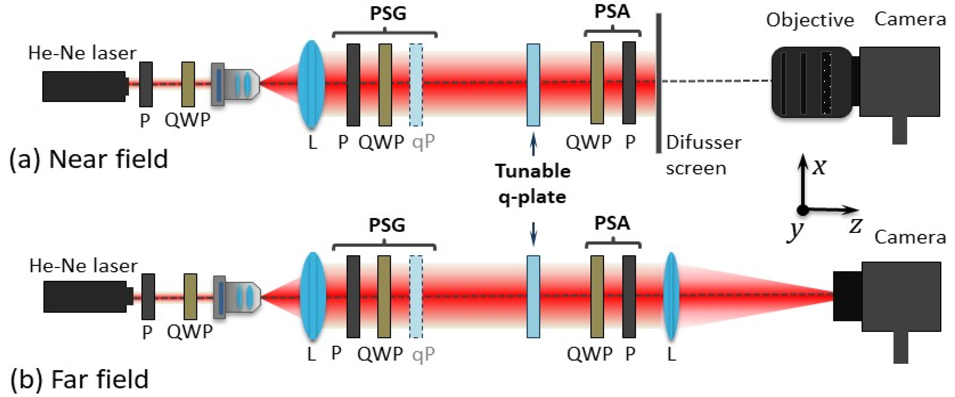
2.3. Experimental System

In this work we use a tunable liquid-crystal commercial q-plate from Arcoptix [30] (named variable spiral plate). To our knowledge, this is the only commercial q-plate device with tunable retardance. The possibility of tuning the retardance via an applied voltage allows us to operate the device at different wavelengths and to tune the polarization conversion efficiency, as described by Equation (1). Here we use it to generate hybrid vector beams and experimentally analyze their propagation.
The q-value of this device is q = 1/2 and its nominal operational wavelength range is 400–1700 nm. The device has a circular clear aperture with a diameter of 1.2 cm (Figure 1a) and we measured a 93% transmittance (ratio of the output intensity to the input intensity). Its retardance is controlled by an AC bias between 0 and 8 V, and it was characterized in a broad spectral range [38]. Mode-division-multiplexing of vector beams at 1550 nm using such commercial q-plate was recently reported [39]. Here, we operate the device at a wavelength of 633 nm and we measured the retardance as a function of the applied voltage following a standard procedure [25,26]. Figure 1b shows the retardance function obtained at this operating wavelength, which exhibits a total variation of more than 2π. We identify the following voltages of interest: (1) at V = 2.45 V the retardance is π, and thus the q-plate provides maximum conversion efficiency in generating pure vector beams; (2) at V = 3.92 V and V = 1.95 V the retardance is π/2 and 3π/2, respectively, thus acting as a quarter-wave q-plate (QW q-plate). In the present work the q-plate is always set at 3π/2 retardance.
Figure 2 shows a scheme of the experimental setup. A He-Ne laser of wavelength 633 nm is spatially filtered and collimated. A linear polarizer and a quarter-wave plate (QWP) placed before the spatial filter makes the light beam circularly polarized, so the next polarizer can be rotated without changing the input intensity. Behind the collimating lens, a polarization state generator (PSG) consisting of another rotatable polarizer–QWP pair generates the state of polarization entering the tunable q-plate (this state will be henceforth referred to as input state). In some cases, the PSG will also incorporate a static q-plate in order to have a vortex beam or a vector beam incident on the tunable q-plate. A polarization state analyzer (PSA) placed behind the q-plate projects the output beam onto a given polarization state. The PSA is composed of a QWP and a linear polarizer. In order to compare the near-field (NF) and the far-field (FF) patterns, we use two different configurations.
For NF observations (Figure 2a), the beam is projected onto a diffuser screen. Then, a photographic objective is used for imaging this screen onto the camera detector. In the second case (Figure 2b) a converging lens is added behind the PSA, and the detector is placed at the focal plane, where the FF patterns are observed.

3. Results on the Generation of Standard Hybrid Vector Beams

In this first set of results we consider the tunable q-plate illuminated with a beam of uniform RCP polarization. In all cases, the q-plate is set at 3π/2 retardance (QW q-plate). Thus, if we consider an input beam like V i n = L G 0 e ^ R , the action on this beam, according to Equations (3) and (6), yields the following output
V o u t = 1 2 ( L G 0 e ^ R i L G 0 1 e ^ L )
where it is used that q = 1/2 for this device. This output describes a hybrid vector beam of the form of Equation (7) with R = and L = 1 , δ = π/4 and φ = −π/4. The difference | R | | L | = ± 1 is the lowest possible value, so the approximations in Equations (9)–(11) are in the best case. Since the semi-difference charge is m = 1/2 for any value of , the NF polarization pattern exhibits a half rotation of the azimuth along the polar coordinate, whereas the FF is affected by a Gouy phase shift 1 2 Δ ψ G ( z ) = ± π 4 ( | | | 1 | ) . We consider next two cases to illustrate these properties: = 0 and = 2 .

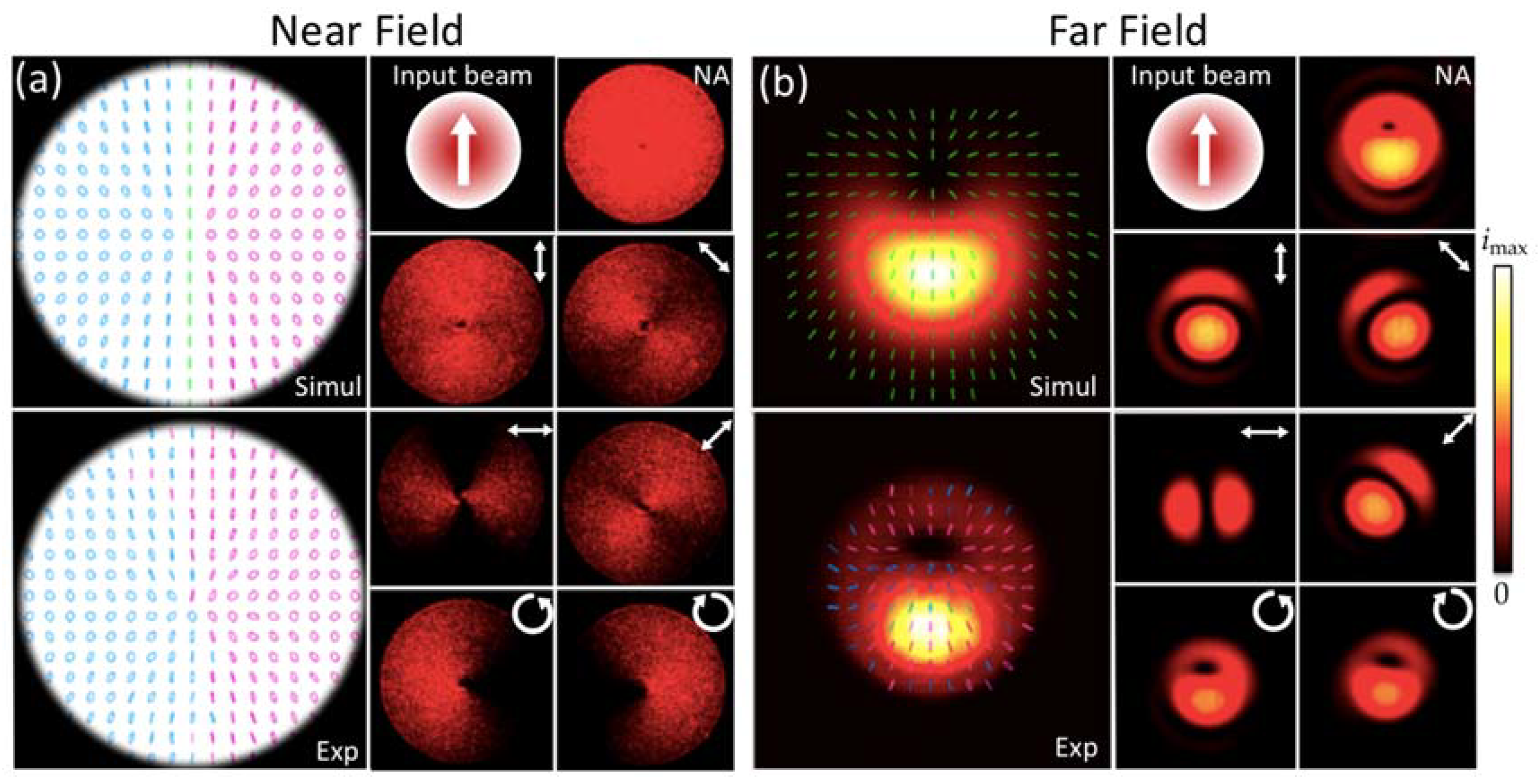
3.1. Case with Input Circularly Polarized Gaussian Beam

We first consider = 0 , i.e., the input beam is an RCP L G 0 Gaussian beam. This simple case was analyzed in the far field in [30] and we include it here to compare with the next cases. According to Equation (12) the output is V o u t = 1 2 ( L G 0 0 e ^ R i L G 0 1 e ^ L ) . Therefore, this hybrid vector beam is a Poincaré beam with fractional order m = 1/2. Figure 3 shows numerical and experimental results in the NF (Figure 3a) and in the FF (Figure 3b). For each case we show Matlab numerical calculations using the exact relation in Equation (8) (Simul) and the corresponding experimental results (Exp). For the NF calculations we simply illustrate the polarization map, since the experiments only show the central area of the beam, cropped with a diaphragm. For the FF, the image shows the polarization map and the intensity distribution. Right and left-handed states are depicted in magenta and cyan ellipses respectively. Linear polarization is depicted in green. The experimental captures, both for NF and FF, are the images in the two columns to the right of the polarization maps. In each case we show captures without analyzer (NA) and with analyzers transmitting the typical polarization states (linear vertical and horizontal, linear at ±45, RCP and LCP). The experimental polarization maps are obtained by deriving the Stokes parameters from the experimental images. Note that the FF images here displayed were saturated in order to better visualize the intensity pattern, but equivalent non-saturated images were used to calculate the polarization maps. The FF experimental intensity distribution corresponds to the averaged S0 Stokes parameter. The cases analyzed in the rest of the paper will present the figures in the same format as Figure 3.
Let us analyze the NF captures (Figure 3a). First, we note that illuminating the QW q-plate with a circular state provides an output that is a spatially-variant linearly polarized beam. Since m = 1/2, the orientation of the linear polarization shows an azimuthal rotation of half a cycle in the complete plane. The polarization pattern is rotated 45° clockwise with respect to the vertical direction due to the angle φ = −π/4. This pattern is experimentally verified in the captures with a linear analyzer, which show a dark lobe opposed to a bright lobe, which rotate as the analyzer does. The captures with circular analyzers show a dark central dot for the LCP component, verifying the phase singularity in this component, while the RCP shows no singularity.
The polarization map in the FF shows different polarization states that change along the azimuthal and radial coordinate, thus manifesting the Poincaré beam nature. The changes along the azimuthal angle can be easily understood by the polarization rotation described in Equation (11). Like in the NF, the captures for linear analyzers show a bright spot that rotates as the analyzer does. However, note the π/2 rotation of the FF intensity compared to the NF, for each orientation of the analyzer. This can be viewed as a consequence of the Gouy phase polarization rotation 1 2 Δ ψ G = π 4 , that causes a 90° counterclockwise rotation of the intensity pattern transmitted by the linear analyzers. Polarization changes along the radial coordinate are a consequence of the different amplitude of the modes encoded on each circular component. The analysis with circular analyzers confirms that there is a phase singularity only for the LCP component, while the RCP component is bright in the center, denoting the absence of singularity. Consequently, the corresponding polarization map shows RCP at the center. This is a C-point polarization singularity, where the orientation of the polarization ellipse is undefined. As we move along the radial direction the polarization becomes linear along a L-line circle that separates the inner and outer regions of opposite handedness. The experimentally measured polarization map agrees well with the simulation.

3.2. Case with Input Circularly Polarized Vortex Beam

Let us now analyze the case with = 2 i.e., the input beam is V i n = L G 0 2 e ^ R . This input state was obtained by illuminating with LCP a static q-plate of q = 1 (Thorlabs WPV10L-633) inserted in the PSG. According to Equation (12) this input RCP vortex beam now provides an output beam given by V o u t = 1 2 ( L G 0 2 e ^ R i L G 0 1 e ^ L ) . This hybrid vector beam is the superposition of two vortex beams of charges R = 2 and L = 1 .
Figure 4 shows the corresponding numerical and experimental results. As the fractional order is once again m = 1/2, the NF shows the same polarization pattern as in the previous case with = 0 (Figure 3a). However, an important difference in the NF captures is the phase singularity that now appears in both RCP and LCP components. The FF images more clearly reveal the different vortex content in the RCP and LCP components, observed in the different diameter of the focused beam in these components. Unlike in the previous case, now the Gouy phase polarization rotation is 1 2 Δ ψ G = π 4 , and consequently, the FF shows a 45° counterclockwise polarization rotation with respect to the NF. Again, this is clearly seen in the 90° clockwise rotation of the FF intensity patterns compared to the NF patterns obtained for each linear analyzer. The experimental and simulated polarization maps also evidence this polarization rotation. This rotation is exact at the L-line that separates the inner and outer regions with opposite handedness.

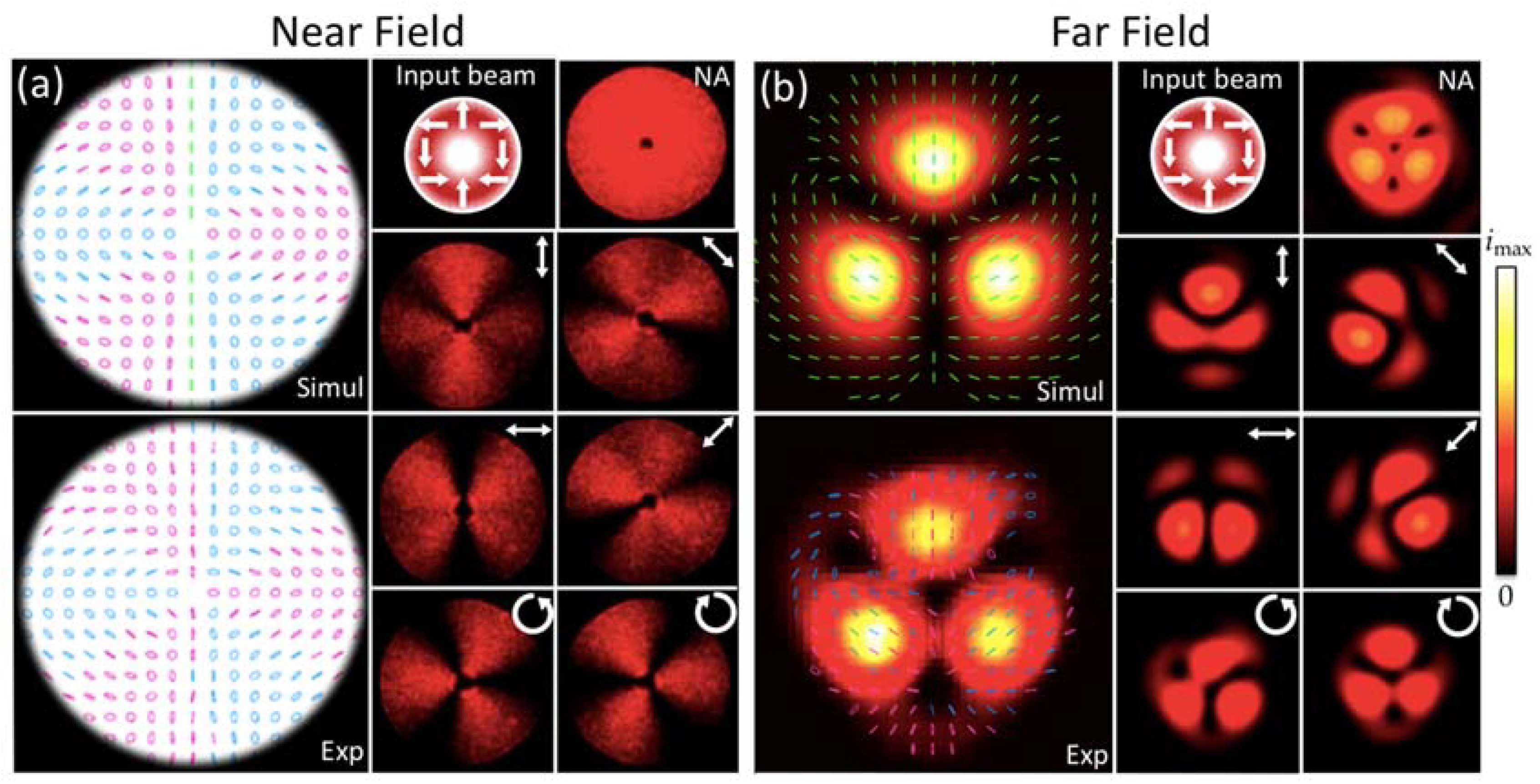
4. Results on the Generation of Hybrid Petal-Type Vector Beams

In this second set of experiments we generate more complex hybrid vector beams which are superpositions of two LG modes on both RCP and LCP components. They are obtained by illuminating the tunable q-plate with homogeneous linear polarization or with radial polarization. In these cases, the QW q-plate provides outputs that exhibit crossed terms in the circular polarizations that yield the two-mode superposition, which gives intensity lobes along the polar coordinate.

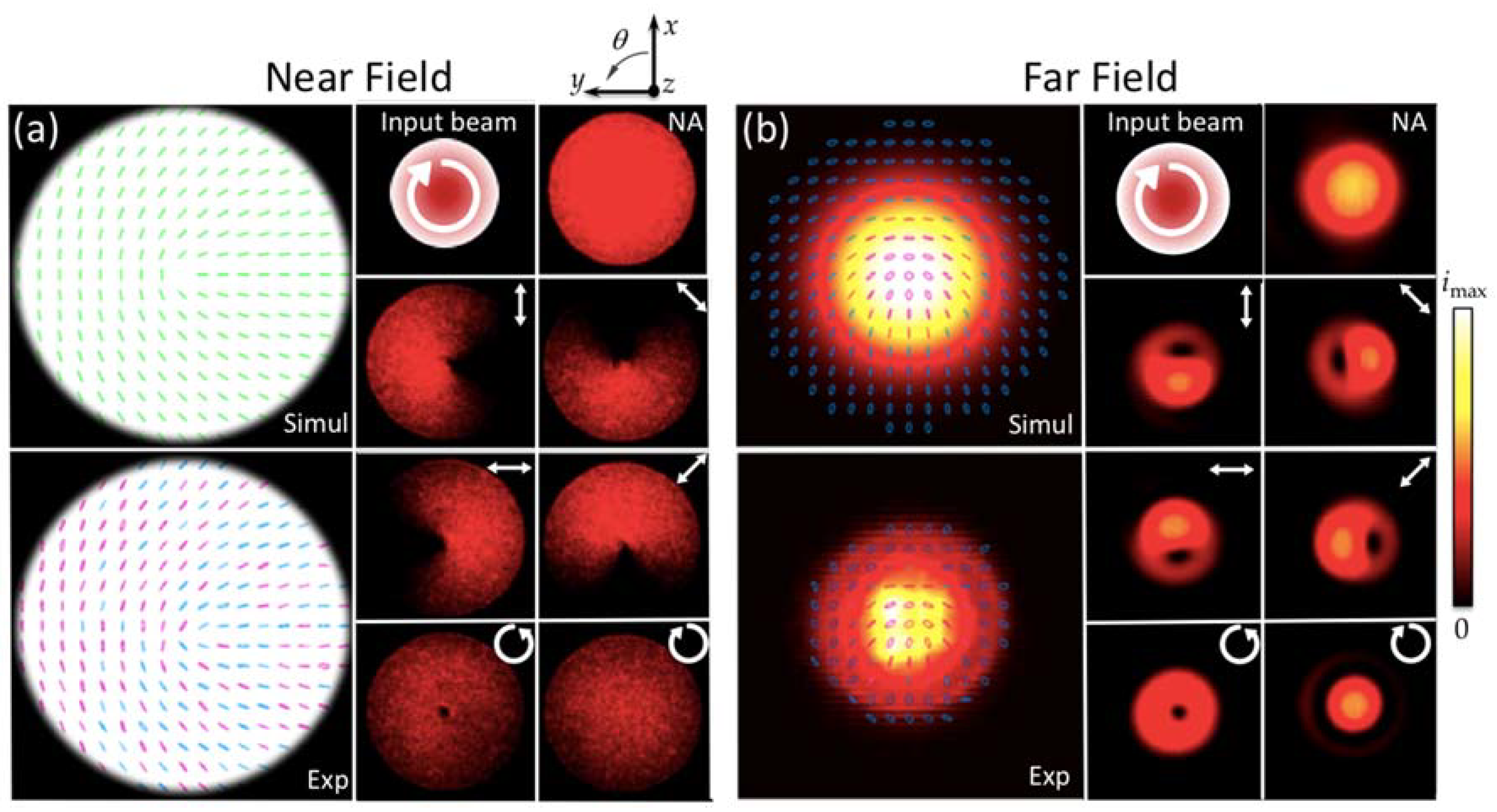
4.1. Case with Input Homogeneous Linearly Polarized Gaussian Beam

First, we consider an input L G 0 0 beam with linear vertical polarization, i.e., V i n = L G 0 0 2 ( e ^ R + e ^ L ) . According to Equations (3) and (6), after combining terms, the output beam reads:
V o u t = 1 2 [ ( L G 0 0 i L G 0 1 ) e ^ R + ( L G 0 0 i L G 0 1 ) e ^ L ]
This output beam is therefore generated by the superposition of the fundamental L G 0 0 mode with a L G 0 ± 1 mode in each polarization component. Figure 5 shows the corresponding results in the NF and FF. Due to the azimuthal phase difference in each polarization component, this superposition results in a NF polarization map which is specularly symmetric, with a straight vertical line dividing two regions of opposite handedness. This is clearly seen in the RCP and LCP components at the NF, which show two specularly symmetric intensity patterns with one dark azimuthal lobe at the left or right part of the beam, respectively.
Like in previous cases, the propagation to the FF is affected by the different Gouy phase of each LG component. However, now, each polarization component is already carrying two modes. The Gouy phase difference between modes L G 0 0 and L G 0 ± 1 , produces a ±90° rotation of the intensity pattern of the circular polarization components from NF to FF. This is shown in the FF patterns in Figure 5b. As this rotation is in the opposite sense for RCP and LCP components, the two intensity patterns match in the FF, having a minimum at θ = 0 (upper vertical direction) while being maximum at θ = π (lower vertical direction). As a consequence, the FF intensity pattern without analyzer presents one lobe located in the lower part of the beam, the polarization becomes linear at every point, and an off-axis singularity appears in the upper part of the FF intensity pattern. Let us note that the projection of the output vector beam over a horizontal linear analyzer yields a horizontally polarized sum of LG modes with = ± 1 , with a relative phase of π between them. This results in a Hermite–Gauss mode H G 01 . The amplitude of this mode does not change with propagation, as can be seen comparing the NF and FF intensity patterns for the horizontal analyzer. As we will show next, this case is just a particular situation of a more general case of petal-type beams encoded onto the two circular polarizations.

4.2. Case with Input Higher-Order Radial Polarization

In this section we study the resulting beam when illuminating the QW q-plate with a pure radial beam of order . These beams are described by the following relation:
V o u t = 1 2 [ L G 0 e ^ R + L G 0 e ^ L ]
The output vector beam, after applying Equations (3) and (6), adopts the form of a more complex non-separable structure of wavefront and local polarization which reads
V o u t = 1 2 [ ( L G 0 i L G 0 ( 1 ) ) e ^ R + ( L G 0 i L G 0 1 ) e ^ L ]
Like in the previous case, there is a superposition of two LG modes in each circular polarization. This superposition generates sidelobes along the azimuthal coordinate for each circular component due to the azimuthal phase difference between each pair of LG modes. This situation is similar to the superposition that generates scalar beams with angular lobes, in what has been named as petal beams [40].
In order to gain physical insight of these angular lobes, we consider an approximation where we ignore the difference in the modes’ amplitude, i.e., we assume u 1 ( z ) u ( z ) . Within this approximation we can consider that
1 2 ( L G 0 i L G 0 ( 1 ) ) u ( z ) W e i θ / 2 cos { 1 2 [ ( 2 1 ) θ Δ ( z ) + π 2 ] }
1 2 ( L G 0 i L G 0 1 ) u ( z ) W e i θ / 2 cos { 1 2 [ ( 2 1 ) θ Δ ( z ) + π 2 ] }
where W = e i ( 2 + | | + | 1 ) ξ ( z ) / 2 e i π / 4 is a global phase and Δ ( z ) = ( | | | 1 | ) ξ ( z ) denotes the Gouy phase difference between the modes L G 0 and L G 0 ± ( 1 ) . Note that this Gouy phase shift is different to that in Equation (10), which is the phase difference between the RCP and LCP components. Instead, Δ ( z ) is the phase shift between the two modes now encoded in each circular polarization. The intensity of the RCP and of the LCP components, within this approximation, is given by
i R ( z ) | u | 2 ( 1 + sin [ ( 2 1 ) θ + Δ ( z ) ] )
i L ( z ) | u | 2 ( 1 sin [ ( 2 1 ) θ Δ ( z ) ] )
These relations indicate that the intensity of each circular polarization component show ( 2 1 ) lobes along the polar coordinate. Since Δ ( z ) = 0 in the NF the patterns i R and i L are complementary. However, propagation produces an opposite rotation of the lobes in each polarization component. Noting that | | | 1 | = ± 1 (positive for 0 and negative for < 0 ), then Δ ( z ) = ± π / 2 in the FF limit, and the two sidelobes patterns perfectly match since the two relations in Equations (17a) and (17b) become the same:
i R ( z ) = i L ( z ) | u | 2 ( 1 ± cos [ ( 2 1 ) θ ]
Figure 6 shows the corresponding results for a 2nd-order radial beam as input state, i.e., the situation for the value = 2 . This input vector beam incident on the QW q-plate was obtained by adding a static q-plate of q = 1 to the PSG. The numerically calculated NF polarization map (Figure 6a) shows three L-lines that separate angular sectors of opposite handedness. The experimentally retrieved polarization map matches very well this calculation. Note how the RCP and LCP components show 2 1 = 3 lobes along the polar coordinate, and how they are complementary to each other, thus leading to the absence of lobes for the image without analyzer.
The situation changes in the corresponding FF patterns (Figure 6b). Now the two RCP and LCP lobes rotate in the opposite sense until they match in the FF. This is the reason why the intensity pattern without analyzer presents three lobes, and the polarization map is always linearly polarized (the two circular polarization components have equal amplitude). In addition to the central singularity, the pattern presents another three off-axis singularities. The experimentally measured intensity and polarization map agrees very well with the numerical results.
Note that the case in the previous section is a particular case of this situation with = 0 . Let us also remark that these results are equivalent to the superpositions of Gaussian vector beams theoretically analyzed in [41].

5. Conclusions

This work shows the possibilities of an electrically tunable q-plate to generate different kinds of vector beams and study their dynamics. This device is commercially available, therefore useful for researchers with no fabrication facilities. We employed a liquid-crystal q-plate from the company Arcoptix, with retardance addressable by voltage and a broadband operation that covers the VIS and NIR ranges. While in the standard operation it is used to generate pure vector beams at any wavelength by tuning the device to half-wave retardance (HW q-plate), here we employed it at quarter-wave retardance (QW q-plate) to generate different kinds of hybrid vector beams. Standard hybrid vector beams and more complex petal-like hybrid vector beams were generated when the input beam on the device is a Gaussian beam, a vortex or a pure vector beam. We built a simple setup to experimentally analyze their propagation dynamics by comparing the intensity and polarization patterns in the near field and in the far field. Since the propagation of a hybrid vector beam is affected by the Gouy phase of the different LG modes constituting the beam, we developed an analytical approximation that describes the polarization patterns in terms of mode superpositions and their transformation upon propagation based on their different Gouy phase. The experimental results bear good agreement with numerical and analytical results within the frame of this approximation.
We illustrated how simple hybrid vector beams (superposition of RCP and LCP components with one single but different LG mode) generate the same polarization pattern in the near field, provided the half-difference m = 1/2 is the same. We showed that these hybrid beams are affected by the different Gouy phase of the circular polarization components, causing a significant rotation of the polarization pattern in the far field. As the charge of our q-plate is q = 1/2, it creates hybrid vector beams of m = 1/2 when detuned to a QW retardance. Thus, when focused, the far field RCP and LCP components show a good overlap and the resulting pattern is fairly well described as a polarization rotation driven by the Gouy phase difference between components.
We analyzed a second set of hybrid beams, which are the superposition of two different LG modes on each RCP and LCP component. These more complex beams are generated by illuminating the QW q-plate with a homogeneous linearly polarized beam or with a higher-order pure vector beam. In this case the output hybrid vector beam presents lobes along the azimuthal coordinate that propagate differently for the RCP and LCP components, but overlap at the far field.
In summary, we used a simple setup to generate hybrid vector beams that is fully based on an electrically tunable commercial q-plate. Although it does not provide the vast flexibility offered by SLM-based systems, this q-plate-based setup holds advantages that could be relevant for technological applications of vector beams. Namely, it is more compact, of easier alignment, and of higher efficiency, since SLM losses caused by pixelization are not present. In addition, similarly to SLM schemes, it can generate a wide variety of pure and hybrid vector beams, allowing to switch from one kind of beam to the other by simply addressing a voltage. Furthermore, although these results were obtained for a wavelength of 633 nm, they can be extended to a broad range of wavelengths. As this tunable q-plate is q = 1/2, we are limited to generate hybrid vector beams where the different modes differ in azimuthal order (topological charge) by only one. Of course, higher differences in the topological charge can be achieved by simply using a QW q-plate of higher q value.

Author Contributions

Conceptualization and Experimental Validation, J.C.Q.-M.; Conceptualization and Software, D.M.; Conceptualization, Funding Acquisition, Supervision, and Writing, M.d.M.S.-L. and I.M.; Conceptualization and Supervision, E.S. All authors have read and agreed to the published version of the manuscript.

Funding

This research was funded by Generalitat Valenciana, Conselleria d’Educació, Investigació, Cultura i Esport (grant PROMETEO-2017-154) and by Ministerio de Ciencia, Innovación y Universidades, Spain (grant RTI2018-097107-B-C33).

Conflicts of Interest

The authors declare no conflict of interest.

References

  1. Zhan, Q. Cylindrical vector beams: From mathematical concepts to applications. Adv. Opt. Photonics 2009, 1, 1–57. [Google Scholar] [CrossRef]
  2. Gbur, G.J. Singular Optics; CRC Press/Taylor & Francis Group: Boca Raton, FL, USA, 2016. [Google Scholar]
  3. Rosales-Guzmán, C.; Ndagano, B.; Forbes, A. A review of complex vector light fields and their applications. J. Opt. 2018, 20, 123001. [Google Scholar] [CrossRef]
  4. Yi, X.; Liu, Y.; Ling, X.; Zhou, X.; Ke, Y.; Luo, H.; Wen, S.; Fan, D. Hybrid-order Poincaré sphere. Phys. Rev. A 2015, 91, 023801. [Google Scholar] [CrossRef] [Green Version]
  5. Khajavia, B.; Galvez, E.J. Preparation of Poincaré beams with a same-path polarization/spatial-mode interferometer. Opt. Eng. 2015, 54, 1–6. [Google Scholar] [CrossRef]
  6. Zhou, H.; Fu, S.; Zhai, Y.; Yin, C.; Gao, C. Spatial light modulator-based programmable J-plate for the arbitrary spin-to-orbital angular momentum conversion of lights. Appl. Phys. B 2019, 125, 42. [Google Scholar] [CrossRef]
  7. García-Martínez, P.; Marco, D.; Martínez-Fuentes, J.L.; Sánchez-López, M.M.; Moreno, I. Efficient on-axis SLM engineering of vector modes. Opt. Lasers Eng. 2020, 125, 105859. [Google Scholar] [CrossRef]
  8. Pradhan, P.; Sharma, M.; Ung, B. Generation of perfect cylindrical vector beams with complete control over the ring width and ring diameter. IEEE Photon. J. 2018, 10, 1–10. [Google Scholar] [CrossRef]
  9. Karpeev, S.V.; Podlipnov, V.V.; Khonina, S.N.; Paranin, V.D.; Tukmakov, K.N. Anisotropic diffractive optical element for generating hybrid-polarized beams. Opt. Eng. 2019, 58, 082402. [Google Scholar]
  10. Lou, S.; Zhou, Y.; Yuan, Y.; Lin, T.; Fan, F.; Wang, X.; Huang, H.; Wen, S. Generation of arbitrary vector vortex beams on hybrid-order Poincaré sphere based on liquid crystal device. Opt. Express 2019, 27, 8596–8604. [Google Scholar] [CrossRef]
  11. Chen, J.; Xu, Q.; Han, J. Polarization-selective holographic metasurface for creating cylindrical vector beams. IEEE Photon. J. 2019, 11, 1–9. [Google Scholar] [CrossRef]
  12. Crăciun, A.; Dascălu, T. A method to generate vector beams with adjustable amplitude in the focal plane. Appl. Sci. 2020, 10, 2313. [Google Scholar] [CrossRef] [Green Version]
  13. Niv, A.; Biener, G.; Kleiner, V.; Hasman, E. Manipulation of the Pancharatnam phase in vectorial vortices. Opt. Express 2006, 14, 4208–4220. [Google Scholar] [CrossRef] [PubMed]
  14. Liu, Z.; Liu, Y.; Ke, Y.; Liu, Y.; Shu, W.; Luo, H.; Wen, S. Generation of arbitrary vector vortex beams on hybrid-order Poincaré sphere. Photon. Res. 2017, 5, 15–21. [Google Scholar] [CrossRef] [Green Version]
  15. He, Y.; Ye, H.; Liu, J.; Xie, Z.; Zhang, X.; Xiang, Y.; Chen, S.; Li, Y.; Fan, D. Order-controllable cylindrical vector vortex beam generation by using spatial light modulator and cascaded metasurfaces. IEEE Photon. J. 2017, 9, 1–10. [Google Scholar] [CrossRef]
  16. Mamani, M.; Bendau, E.; Secor, J.; Ashrafi, S.; Tu, J.J.; Alfano, R.R. Hybrid generation and analysis of vector vortex beams. Appl. Opt. 2017, 56, 2171–2175. [Google Scholar] [CrossRef]
  17. Devlin, R.C.; Ambrosio, A.; Rubin, N.A.; Mueller, J.P.B.; Capasso, F. Arbitrary spin-to–orbital angular momentum conversion of light. Science 2017, 358, 896–901. [Google Scholar] [CrossRef] [Green Version]
  18. Beckley, A.M.; Brown, T.G.; Alonso, M.A. Full Poincaré beams. Opt. Express 2010, 18, 10777–10785. [Google Scholar] [CrossRef]
  19. Suárez-Bermejo, J.C.; González de Sande, J.C.; Santarsiero, M.; Piquero, G. Mueller matrix polarimetry using full Poincaré beams. Opt. Laser Eng. 2019, 122, 134–141. [Google Scholar] [CrossRef]
  20. Galvez, E.J.; Khadka, S.; Schubert, W.H.; Nomoto, S. Poincaré-beam patterns produced by nonseparable superpositions of Laguerre-Gauss and polarization modes of light. Appl. Opt. 2012, 51, 2925–2934. [Google Scholar] [CrossRef] [Green Version]
  21. Davis, J.A.; McNamara, D.E.; Cottrell, D.M.; Sonehara, T. Two-dimensional polarization encoding with a phase-only liquid-crystal spatial light modulator. Appl. Opt. 2000, 39, 1549–1554. [Google Scholar] [CrossRef]
  22. Ling, X.; Yi, X.; Dai, Z.; Wang, Y.; Chen, L. Characterization and manipulation of full Poincaré beams on the hybrid Poincaré sphere. J. Opt. Soc. Am. B 2016, 33, 2172–2176. [Google Scholar] [CrossRef]
  23. Marrucci, L.; Manzo, C.; Paparo, D. Optical spin-to-orbital angular momentum conversion in inhomogeneous anisotropic media. Phys. Rev. Lett. 2006, 96, 163905. [Google Scholar] [CrossRef] [PubMed] [Green Version]
  24. Rubano, A.; Cardano, F.; Piccirillo, B.; Marrucci, L. Q-plate technology: A progress review. J. Opt. Soc. Am. B 2019, 36, D70–D87. [Google Scholar] [CrossRef] [Green Version]
  25. Slussarenko, S.; Murauski, A.; Du, T.; Chigrinov, V.; Marrucci, L.; Santamato, E. Tunable liquid crystal q-plates with arbitrary topological charge. Opt. Express 2011, 19, 4085–4090. [Google Scholar] [CrossRef] [Green Version]
  26. Davis, J.A.; Hashimoto, N.; Kurihara, M.; Hurtado, E.; Pierce, M.; Sánchez-López, M.M.; Badham, K.; Moreno, I. Analysis of a segmented q-plate tunable retarder for the generation of first-order vector beams. Appl. Opt. 2015, 54, 9583–9590. [Google Scholar] [CrossRef]
  27. Beresna, M.; Gecevicius, M.; Kazansky, P.G.; Gertus, T. Radially polarized optical vortex converter created by femtosecond laser nanostructuring of glass. Appl. Phys. Lett. 2011, 98, 201101. [Google Scholar] [CrossRef]
  28. Sánchez-López, M.M.; Abella, I.; Puerto-García, D.; Davis, J.A.; Moreno, I. Spectral performance of a zero-order liquid-crystal polymer commercial q-plate for the generation of vector beams at different wavelengths. Opt. Laser Technol. 2018, 106, 168–176. [Google Scholar] [CrossRef]
  29. Cardano, F.; Massa, F.; Qassim, H.; Karimi, E.; Slussarenko, S.; Paparo, D.; de Lisio, C.; Sciarrino, F.; Santamato, E.; Boyd, R.W.; et al. Quantum walks and wavepacket dynamics on a lattice with twisted photons. Sci. Adv. 2015, 1, e1500087. [Google Scholar] [CrossRef] [Green Version]
  30. Arcoptix Switzerland, Manufacturer of FTIR / FT-NIR Spectrometers & Liquid Crystal Elements. Available online: http://www.arcoptix.com/Q_Plate.htm (accessed on 20 March 2020).
  31. Cardano, F.; Karimi, E.; Marrucci, L.; de Lisio, C.; Santamato, E. Generation and dynamics of optical beams with polarization singularities. Opt. Express 2013, 21, 8815–8820. [Google Scholar] [CrossRef] [Green Version]
  32. Zhang, Y.; Guo, X.; Han, L.; Li, P.; Liu, S.; Cheng, H.; Zhao, J. Gouy phase induced polarization transition of focused vector vortex beams. Opt. Express 2017, 25, 25725–25733. [Google Scholar] [CrossRef]
  33. Sánchez-López, M.M.; Davis, J.A.; Moreno, I.; Cofré, A.; Cottrell, D.M. Gouy phase effects on propagation of pure and hybrid vector beams. Opt. Express 2019, 27, 2374–2386. [Google Scholar] [CrossRef] [PubMed]
  34. Sánchez-López, M.M.; Moreno, I.; Davis, J.A.; Puerto-García, D.; Abella, I.; Delaney, S. Extending the use of commercial q-plates for the generation of high-order and hybrid vector beams. Proc. SPIE 2018, 10744, 1074407. [Google Scholar]
  35. Saleh, B.E.A.; Teich, M.C. Fundamentals of Photonics, 2nd ed.; John Wiley and Sons Inc.: Hoboken, NJ, USA, 2007. [Google Scholar]
  36. Ngcobo, S.; Aït-Ameur, K.; Passilly, N.; Hasnaoui, A.; Forbes, A. Exciting higher-order radial Laguerre-Gaussian modes in a diode-pumped solid-state laser resonator. Appl. Opt. 2013, 52, 2093–2101. [Google Scholar] [CrossRef] [PubMed]
  37. Karimi, E.; Zito, G.; Piccirillo, B.; Marrucci, L.; Santamato, E. Hypergeometric-Gaussian modes. Opt. Lett. 2007, 32, 3053–3055. [Google Scholar] [CrossRef] [PubMed] [Green Version]
  38. Marco, D.; Sánchez-López, M.M.; García-Martínez, P.; Moreno, I. Using birefringence colors to evaluate a tunable liquid-crystal q-plate. J. Opt. Soc. Am. B 2019, 36, D34–D41. [Google Scholar] [CrossRef]
  39. Zhang, J.; Li, F.; Li, J.; Li, Z. 95.16-Gb/s Mode-Division-Multiplexing signal transmission in free space enabled by effective-conversion of vector beams. IEEE Photon. J. 2017, 9, 1–9. [Google Scholar] [CrossRef]
  40. Litvin, I.A.; Burger, L.; Forbes, A. Angular self-reconstruction of petal-like beams. Opt. Lett. 2013, 38, 3363–3365. [Google Scholar] [CrossRef] [Green Version]
  41. Vyas, S.; Kozawa, Y.; Sato, S. Polarization singularities in superposition of vector beams. Opt. Express 2013, 21, 8972–8986. [Google Scholar] [CrossRef]
Figure 1. (a) Picture of the tunable Arcoptix q-plate. (b) Measured optical retardance of the Arcoptix q-plate as a function of the applied voltage for the 633 nm wavelength.
Applsci 10 03427 g001
Figure 2. Optical setups for the generation of vector beams. (a) Setup to capture the near field. (b) Setup to capture the far field. P: linear polarizer; QWP: quarter-wave plate; qP: static q-plate; L: converging lens.
Applsci 10 03427 g002
Figure 3. Results for the QW q-plate illuminated with an RCP Gaussian beam ( = 0 ). (a) Results in the near field; (b) results in the far field. Simulated and experimental polarization maps, with right and left-handed ellipses depicted in magenta and cyan, and linear polarization in green. Experimental images captured for different orientations of the analyzer, indicated as white arrows (NA indicates no analyzer).
Applsci 10 03427 g003
Figure 4. Results for the QW q-plate illuminated with an RCP vortex beam with = 2 . (a) Results in the near field; (b) results in the far field. Simulated and experimental polarization maps, with equivalent color representation as in Figure 3. Experimental images captured for different orientations of the analyzer, indicated as white arrows (NA indicates no analyzer).
Applsci 10 03427 g004
Figure 5. Results for a QW q-plate illuminated with linear vertical polarization and = 0 . (a) Results in the near field; (b) results in the far field. Simulated and experimental polarization maps, with equivalent color representation as in Figure 3. Experimental images captured for different orientations of the analyzer, indicated as white arrows (NA indicates no analyzer).
Applsci 10 03427 g005
Figure 6. Results for a QW q-plate illuminated with a radially polarized beam of order = 2 . (a) Results in the near field; (b) results in the far field. Simulated and experimental polarization maps, with equivalent color representation as in Figure 3. Experimental images captured for different orientations of the analyzer, indicated as white arrows (NA indicates no analyzer).
Applsci 10 03427 g006

