Dynamic Frequency Support from a DFIG-Based Wind Turbine Generator via Virtual Inertia Control


1
Department of Electrical Engineering, Nantong University, Nantong 226019, China
2
Department of Electrical Engineering, Northeast Electric Power University, Jilin 132012, China
*
Authors to whom correspondence should be addressed.
Appl. Sci. 2020, 10(10), 3376; https://doi.org/10.3390/app10103376
Submission received: 26 February 2020
/
Revised: 21 April 2020
/
Accepted: 27 April 2020
/
Published: 13 May 2020
(This article belongs to the Special Issue Applications of Alternative Fuels)
Abstract
:As the penetrated level of wind in power grids increases, the online system inertia becomes weak. Doubly-fed induction generator (DFIG)-based wind turbine generators (WTGs) are required to provide virtual inertia response to support system frequency. The present inertia control strategy with fixed control gain is not suitable and may cause stall of the DFIG-based WTG, as the virtual inertia response potential from the DFIG-based WTG is different with various wind speed conditions. This paper addresses a virtual inertia control method for the DFIG-based WTGs to improve the system frequency stability without causing stalling of the wind turbine for various wind speed conditions. The effectiveness of the proposed virtual inertia control method is investigated in a small system embedded with the DFIG-based WTG. Results demonstrate that the proposed virtual inertia strategy improves the frequency stability without causing the rotor speed security issue. Thus, the proposed control strategy can secure the dynamic system frequency security of power systems under the scenarios of full and partial loads, and, consequently, the proposed method provides a promising solution of ancillary services to power systems.
1. Introduction
As a renewable energy, the wind power integrations have been continuously increasing during the last few years due to air pollutants and energy shortages. Variable-speed wind turbine generators (WTGs) are the most dominating type of wind generation and replace the conventional synchronous generators due to their advantages, namely, maximum mechanical power capture, reduced acoustical noise, and reduced mechanical stresses on the turbine [1,2]. The types of variable-speed WTGs include: doubly-fed induction generator (DFIG)-based WTG (type III) and full-scale converters-based WTGs (type IV). Compared to the full-scale converters-based WTGs, the DFIG-based WTGs are economically viable, as a partial-scale converter system is employed. Thus, as stated in [3], DFIG-based WTGs constitute more than 50% of the installed WTGs.
However, large integrations of DFIG-based WTGs may bring severe challenges on electric power systems. Frequency stability, which is one type of severe challenge, must be solved. The reason is that DFIG-based WTGs decouple the rotor speed from the system frequency; thus, they are unable to provide inertia response. Furthermore, the online system inertia becomes weak [4,5]. Such inertia issues become significant with the penetrated level of wind increase. Therefore, the worsened maximum rate of change of system frequency (df/dt) and system frequency nadir may trigger under frequency load shedding relays [6,7]. Hence, DFIG-based WTGs are required to provide frequency support capability to guarantee the system frequency stability of power systems with high penetrated wind energy [8,9]. As studied in [10], the kinetic energy available from the DFIG-based WTG is 5.25 times that of a synchronous generator when the DFIG-based WTG operates at rated wind speed. Hence, DFIG-based WTGs are better options for supporting the dynamic system frequency.
In [11], DFIG-based WTGs can provide frequency support capability using two possible ways [12,13,14,15,16,17,18,19,20]. The first way injects active power to the electric power grid using reserve power from DFIG-based WTGs [12,13]. However, to obtain reserve power, de-loading operation is needed. This means that DFIG-based WTGs deviate from maximum power point tracking (MPPT) operation using pitch-angle control or over-speed control of the DFIG-based WTG, thereby resulting in significant wind energy loss. The second way injects active power to the electric power grid by releasing the kinetic energy from DFIG-based WTGs without de-loading operation [14,15,16,17,18,19,20].
To provide dynamic frequency support, the authors of [14] suggest employing the df/dt loop and the frequency deviation (∆f) loops as the additional control loops to emulate virtual inertia control response and droop control response, respectively. As the focus of this paper is investigating the effect of the df/dt loop on the dynamic system frequency, only the virtual inertia control is discussed here. In [15,16], the calculated df/dt is used as the input signal to derive the additional power for virtual inertia control. In [17], the performance of virtual inertia control from the DFIG-based WTG with different control gains is investigated. To increase the frequency stability, the authors of [18] suggested using the maximum df/dt for virtual inertia control. However, the use of the fixed control gain of the virtual inertia control limits the contribution to supporting the dynamic system frequency and has a possibility of resulting in stalling of the DFIG-based WTG in the low region of the rotor speed. In [19,20], a rotor speed-dependent inertia of virtual inertia control is addressed to improve the frequency stability; however, the performance of improving the frequency stability is limited due to the small control gain, particularly for a disturbance.
This paper designs a virtual inertia control strategy with purposes of increasing the system frequency stability and preventing the wind turbine from stalling. In addition, this paper assumes that the DFIG-based WTG operates in MPPT operation mode without preset power reserve. Dynamic performances of the proposed control strategy are investigated in an under-frequency disturbance using electromagnetic transient program restructured version (EMTP-RV) simulator under the scenarios of full and partial loads.
2. Frequency Control of an Electric Power System
Keeping the frequency in the reasonable range is essential for reliable operation of power systems, as the frequency reflects the relationship between the power generation and the load demand. When a frequency event happens, the power system strives to work against the system frequency variation via the inertia response as well as the primary and the secondary frequency controls of synchronous fleets [21]. In other words, conventional synchronous fleets intrinsically release their kinetic energy with a purpose of compensating for the power deficit. Conventional synchronous generators increase input mechanical power to stabilize frequency and arrest the frequency decrease according to the measured rotor speed deviation; afterward, the fast-starting conventional synchronous generators, such as diesel and open-cycle generators, initiate to restore the frequency to 50 Hz or 60 Hz. The relation of the inertia response and the primary frequency control can be given as:
where fsys, fnom, Hsys, and R respectively are system frequency, nominal frequency, system inertia, and droop gain of a power system. ΔPin and ΔPpf indicate the additional output power of the inertia response and the primary frequency control, respectively.
As aforementioned, DFIG-based WTGs decouple the rotor speed from the system frequency. As a result, the frequency deviation and the maximum df/dt become severe and may even trigger the under frequency load shedding relays to prevent the frequency decline further.
3. Model and Control of the DFIG-Based WTG
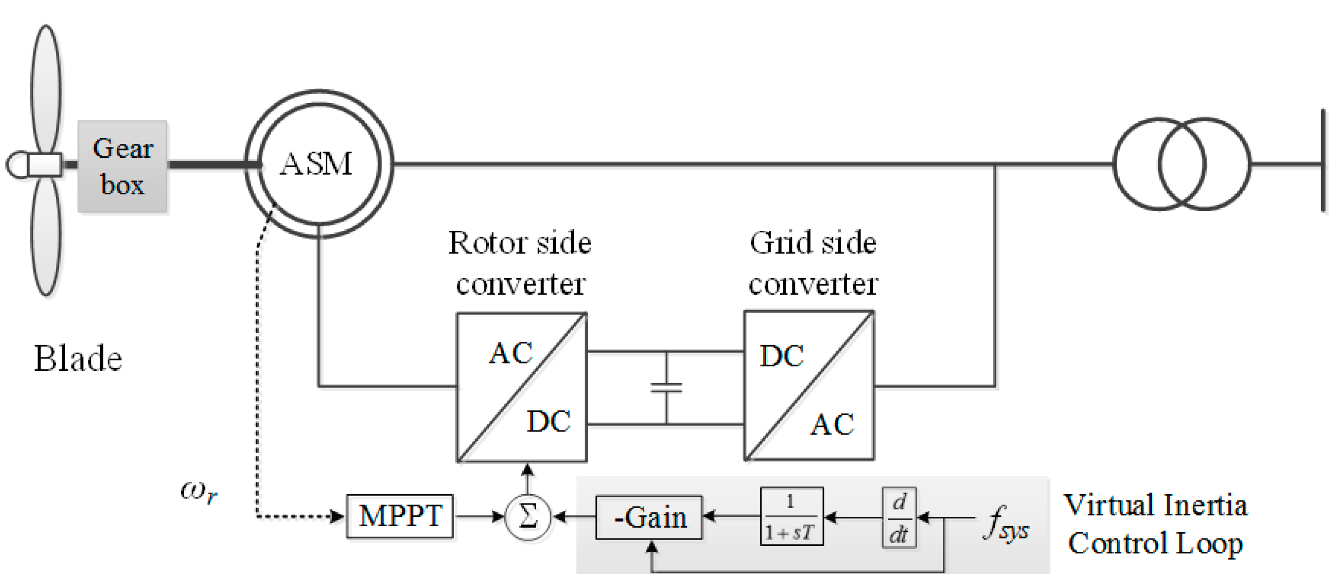
As shown in Figure 1, wind turbine, two masses, induction generator, converters, and control system constitute a DFIG-based WTG.
3.1. Wind Turbine Model
The mechanical power captured from wind—which is a nonlinear function of the wind speed condition (vw), blade profile, etc.—is defined as below:
where ρ means the air density, A means the swept area of the wind turbine, λ indicates the tip-speed ratio, cp represents the power coefficient, and β indicates the pitch angle.
3.2. Two Masses Model
For indicating the dynamics between wind turbine and generator, a two masses model is used [23].
The dynamics between mechanical torque ™ and low speed shaft torque (Tls) are represented as:
where Ht means the inertia constant of the turbine; ωt is the turbine rotor speed.
Dynamics between the electromagnetic torque of a generator (Tem) and high-speed shaft torque (Ths) can be defined as:
where Hg means the inertia constant of the induction generator; ωr is the induction generator rotor speed.
Tls is derived by:
where K, θt, and θls are spring constant, angular displacement of the wind turbine, and angular displacement of the low speed shaft, respectively. B and ωls are the damping constant and the low speed shaft rotor speed, respectively.
3.3. Control of the DFIG-Based WTG
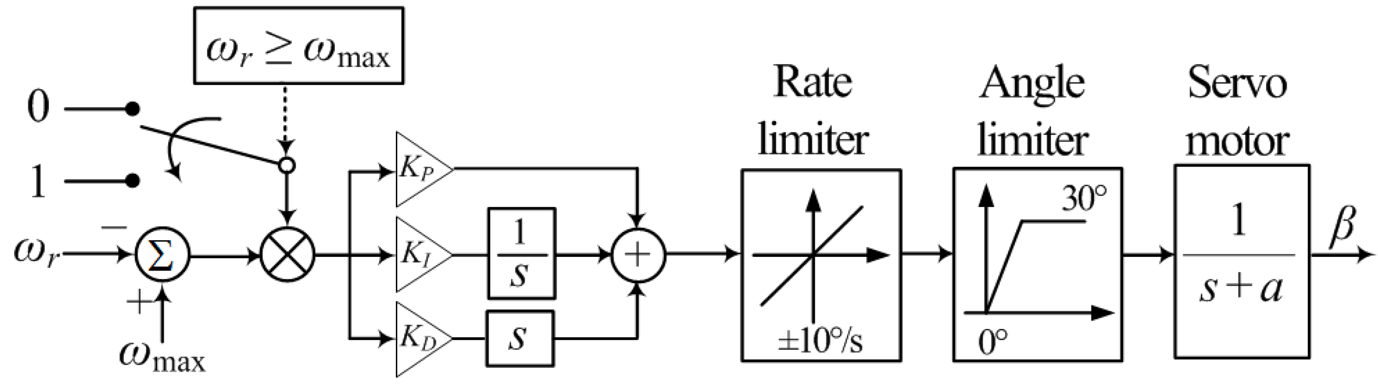
The control system of the DFIG-based WTG includes a pitch angle, a rotor-side converter, and grid-side converter controllers. The function of the pitch-angle controller is to prevent the rotor speed (ωr) from exceeding the maximum value (ωmax), or it is used to enable the de-loading mode according to the command from a high-level controller. The rotor-side converter controller, which achieves decoupled control of reactive power and active power, focuses on maintaining the stator voltage at the regulated value and controls the active power. The gird-side controller focuses on controlling the direct current (DC)-link voltage.
As shown in Figure 2, a rotor speed error between ωr and ωmax is passed through a proportional-integral-derivative (PID) controller to calculate the reference of pitch controller. In addition, the rate and the angle limiters are considered; the setting of maximum pitch angle limit is 30°, and the setting of pitch rate is ±10°/s, as in [24].
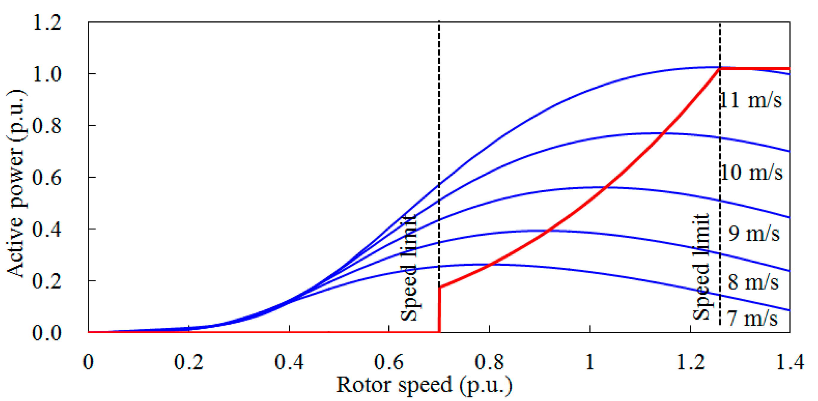
In (3), cp is a function of λ and has a maximum value (cP, max) at the optimal λ (λopt). At the value of λopt, the DFIG-based WTG can capture the maximum Pm from wind [25,26]. Substituting (6) in (3), the power reference for MPPT operation can be represented as:
where kg represents a constant and is set to 0.512. In addition, cP, max is set to 0.5; λopt is set to 9.95 in this study.
Figure 3 indicates Pm curves and PMPPT of the DFIG-based WTG. The ωr operating range of the DFIG-based WTG ranges from 0.70 p.u. to 1.25 p.u., as represented by black dashed lines. The red and the blue solid lines indicate the MPPT curve and the Pm curves, respectively.
The DFIG-based WTG can provide virtual inertial response by adding the df/dt loop to the MPPT control loop, as shown at the bottom of Figure 1. Further, the primary frequency control (droop control) loop is not implemented, as this paper solely studies how to improve the frequency stability from the aspect of the virtual inertia control from a DFIG-based WTG.
4. Proposed Virtual Inertia Control Method of the DFIG-based WTG
As in [15,18], the additional power, ΔPin, calculated by the virtual inertia control is expressed:
where K indicates the control gain of virtual inertia control loop.
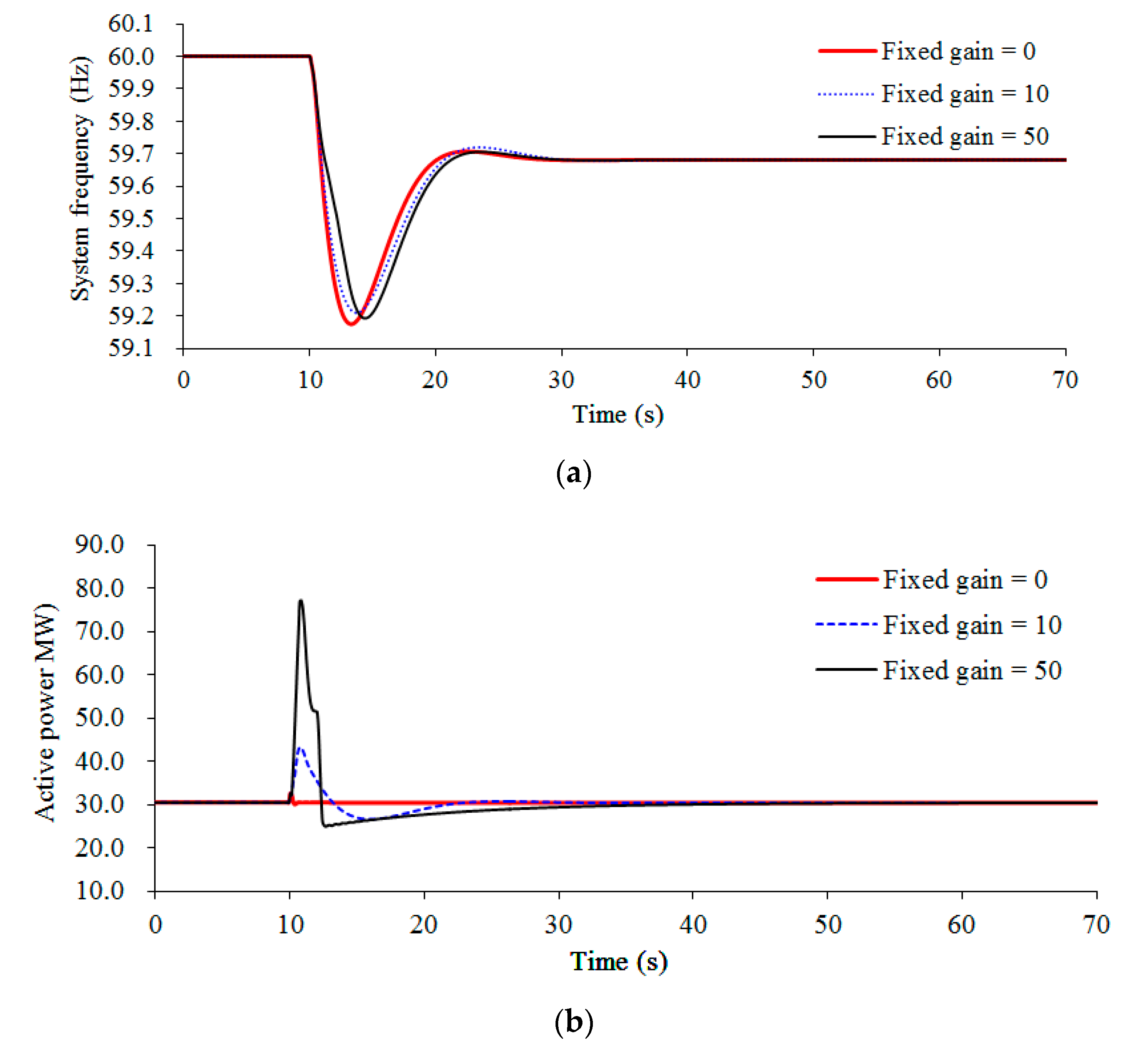
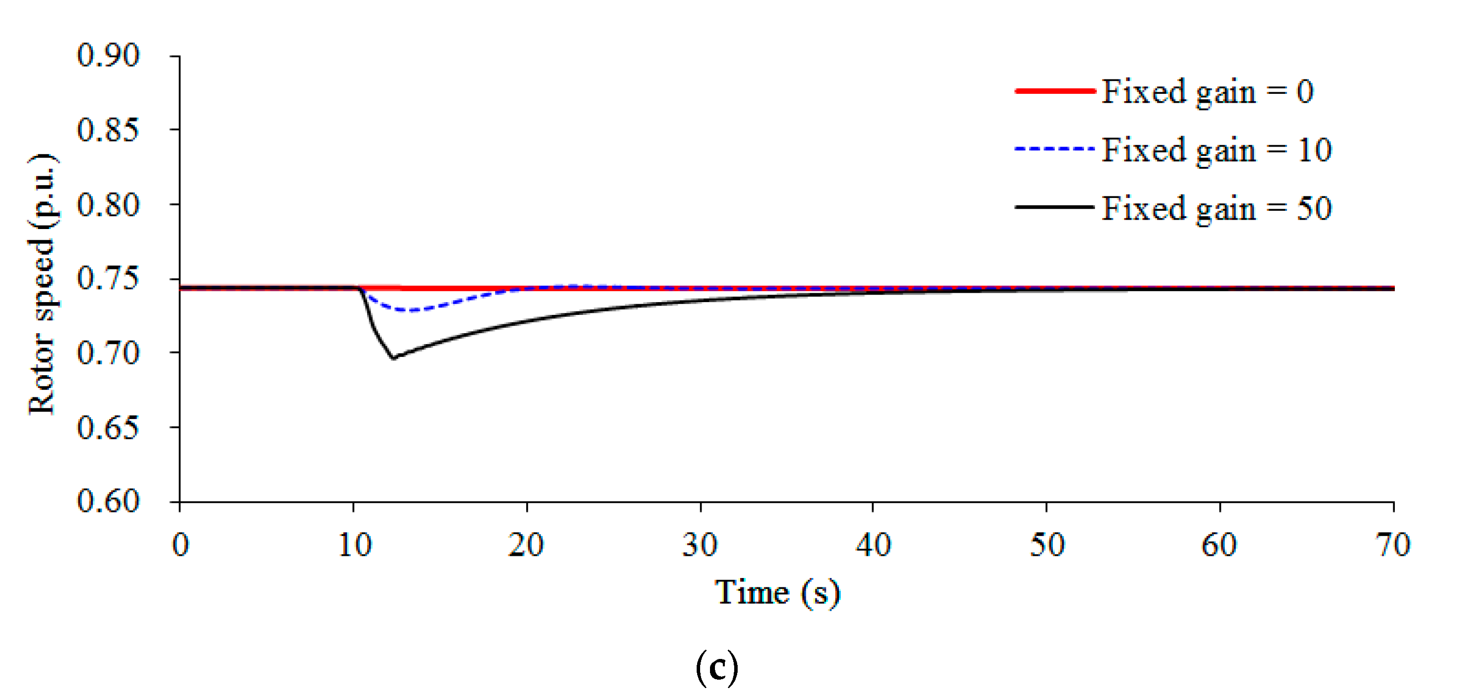
The effect of different control gains on the virtual inertia control is investigated under a low wind speed condition (see Figure 4). Three different control factors of 0, 10, and 50 are considered in the investigation under a low wind speed. The use of a large control gain displays better performance on the maximum df/dt and frequency nadir, as more power is injected to the grid during the initial stage of disturbance. However, when a larger control gain is applied, such as 50 in the investigation, the rotor speed decreases to the minimum value; as a result, stalling of the DFIG-based WTG occurs. Even the released energy in the initial stage of disturbance is more than that when control gain is set to 10, and the maximum frequency deviation is large. Therefore, the use of a large gain can improve the dynamic frequency stability; however, it may have a possibility of causing stalling of the DFIG-based WTG and further worsening the frequency nadir. The use of a small fixed control gain for the conventional strategy is inevitable to prevent the stalling of the DFIG-based WTG, thereby restricting the contribution to improving the frequency stability during disturbance.
To improve the maximum df/dt and frequency nadir and prevent the DFIG-based WTG from stalling, this paper proposes a kinetic energy-dependent control gain. The following sections describe how to define the proposed control gain.
The kinetic energy available of the DFIG-based WTG (Eav) at ωr can be expressed as:
where JDFIG indicates the moment of inertia of the DFIG-based WTG. In this study, the kinetic energy of a DFIG-based WTG is normalized by its rated capacity; thus, the unit of the normalized kinetic energy is seconds.
For the DFIG-based WTG, the capability of virtual inertia control is dependent on the Eav, thus, the control gain, Kpro, in the proposed strategy can be represented as:
where C and ω0 mean the virtual inertia control factor and the rotor speed before disturbance, respectively; the second term of (13) indicates the kinetic energy available from the DFIG-based WTG prior to disturbance.
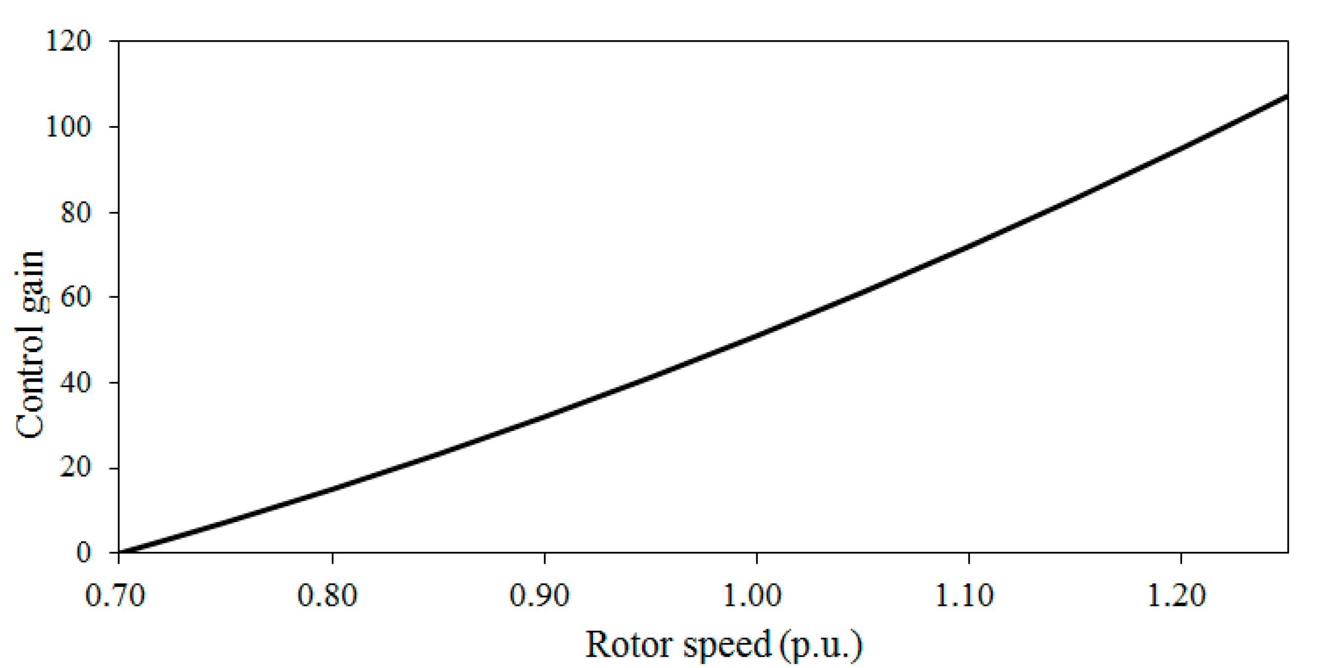
Figure 5 displays the proposed control gain at various rotor speeds when C is set to 100. The control gain is proportional to the rotor speed of the DFIG-based WTG. In the high-rotor-speed region, the use of a large control gain releases more kinetic energy to improve the frequency stability; the use of a small control gain for the low speed region can release suitable energy to support the dynamic system frequency while preventing the DFIG-based WTG from stalling.
As shown in Figure 1, to remove the noise components of the measured system frequency in the virtual inertia control loop, a first order low pass filter is implemented; T is set to 100 ms in this research. Further, Pref calculated by virtual inertia control strategy is limited by the rate of change of power and maximum power limiters to prevent the excessive mechanical stress. The setting of the maximum power limiter is 1.1 times that of the nominal power of the DFIG-based WTG; the setting of the rate of change of power limiter is 0.45 p.u./s [27].
It should be note that only virtual inertia control is implemented in the DFIG-based WTG to support the dynamic system frequency. The adoption of droop control can improve the frequency stability. However, this is out of the scope of this research, as the focus of this paper is investigating how to improve the system frequency stability via virtual inertia control strategy.
5. System Layout
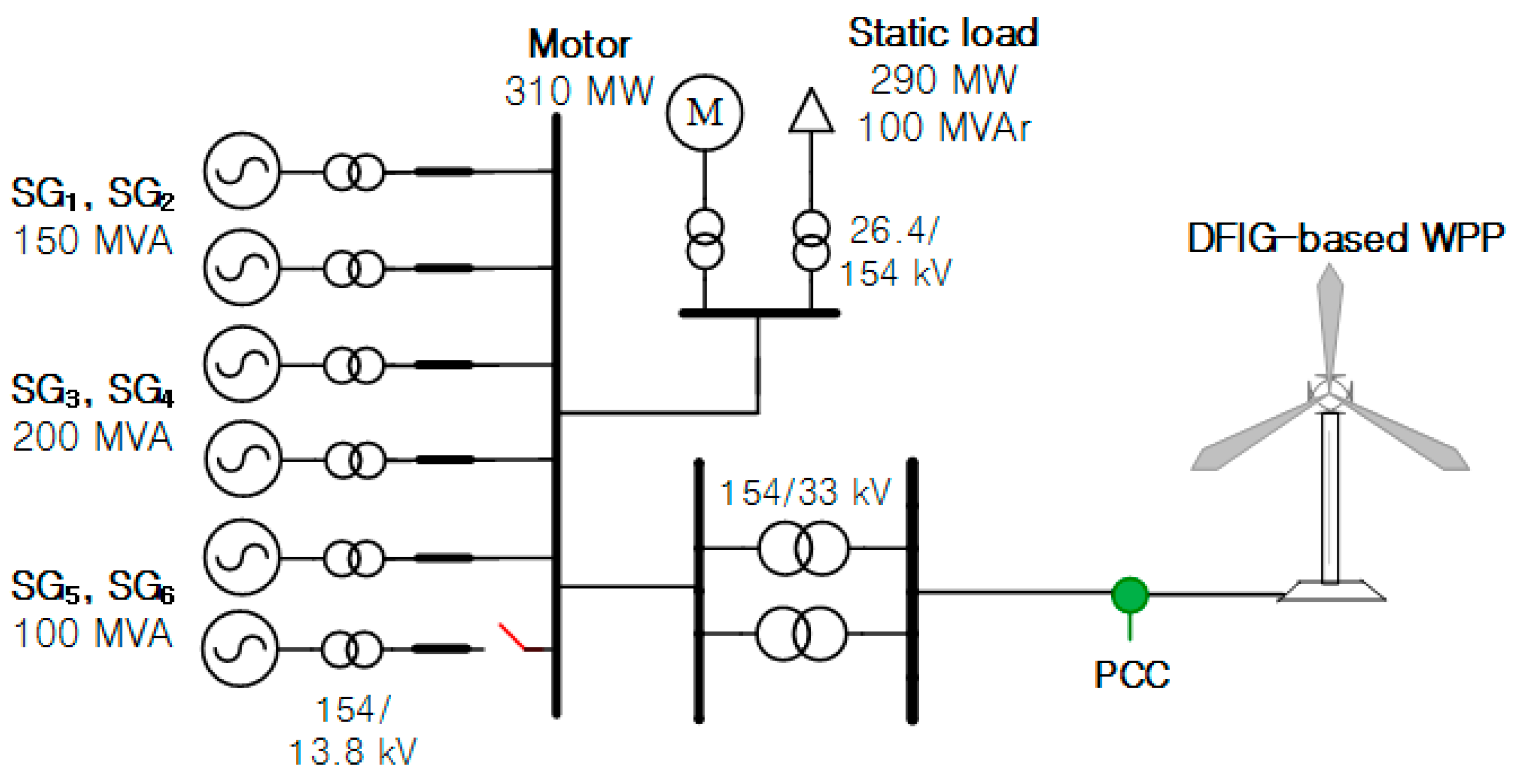
Figure 6 displays a test system including six steam turbine-based synchronous generators, a static load, a motor, and a wind power plant to study the performance of virtual inertia control methods. The specification parameters of synchronous generators and the DFIG-based WTG are represented in Table 1 and Table 2.
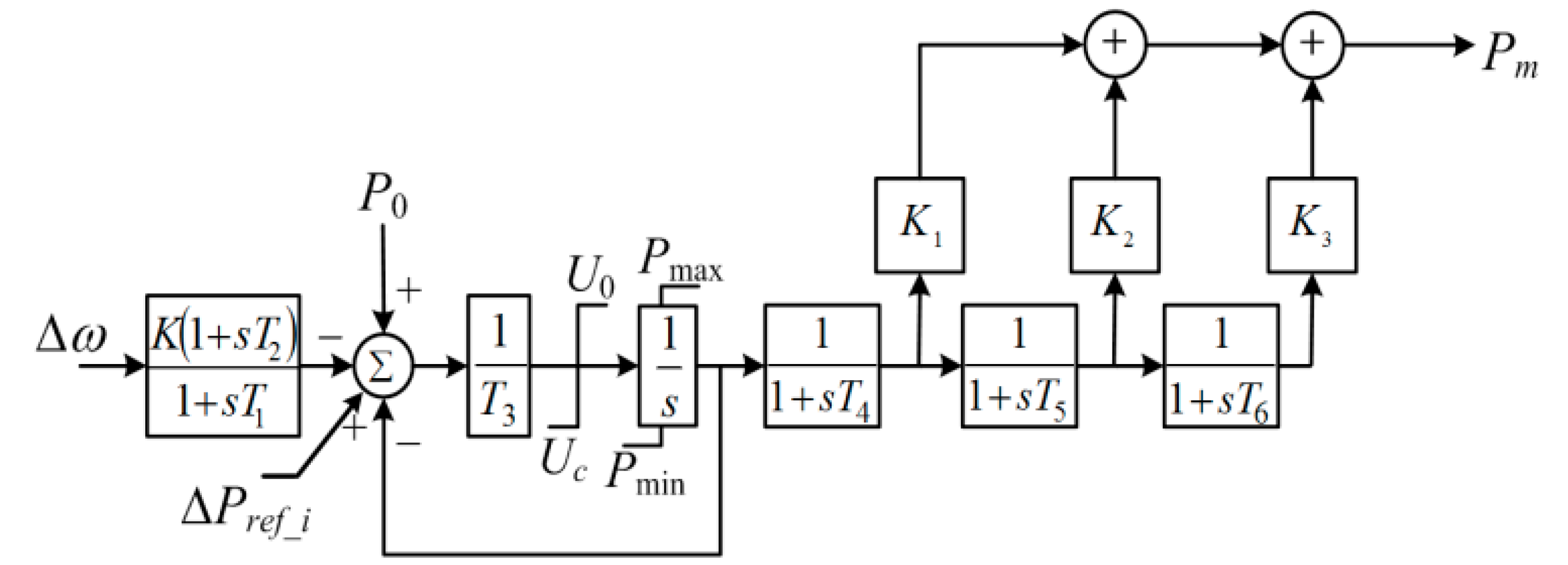
Synchronous generators with the IEEEG1 steam governor model (type B) are selected. Figure 7 represents the topology model of the IEEEG1 steam governor, and Table 3 displays its coefficients, as in [28].
Three simulation scenarios on wind speed conditions of 10.0 m/s, 8.0 m/s, and 13.0 m/s are carried out to investigate the performance of virtual inertia control strategies. As a disturbance, SG6—which generates 90 MW load—trips out from the grid at 10.0 s. Further, the system frequency is calculated by using a phase-locked loop.
To verify the effectiveness of the suggested virtual inertia control method, frequency nadir, maximum df/dt, nadir-based frequency response, and released kinetic energy from the DFIG-based WTG of the proposed strategy are compared to the conventional strategy. Moreover, C is set to 100 to obtain the better performances on improving the maximum df/dt and the frequency deviation. For the conventional strategy, K is set to 10, as in [15].
As in [29], the nadir-based frequency response (NBFR)—which is a metric for assessing the rigidness of an electric power grid—can be expressed as:
where Ploss denotes the loss of active power generation and is 90.0 MW in this research. fnadir is the minimum system frequency during a disturbance.
6. Dynamic Simulation Results
The virtual inertia control capability of a DFIG-based WTG is critically dependent on the kinetic energy available from the DFIG-based WTG, which is related to the wind speed conditions. Thus, the following subsection investigates the capability of virtual inertia control strategies when wind speed conditions are set to 10.0 m/s, 8.0 m/s, and 13.0 m/s, respectively.
6.1. Case 1: Wind Speed = 10.0 m/s
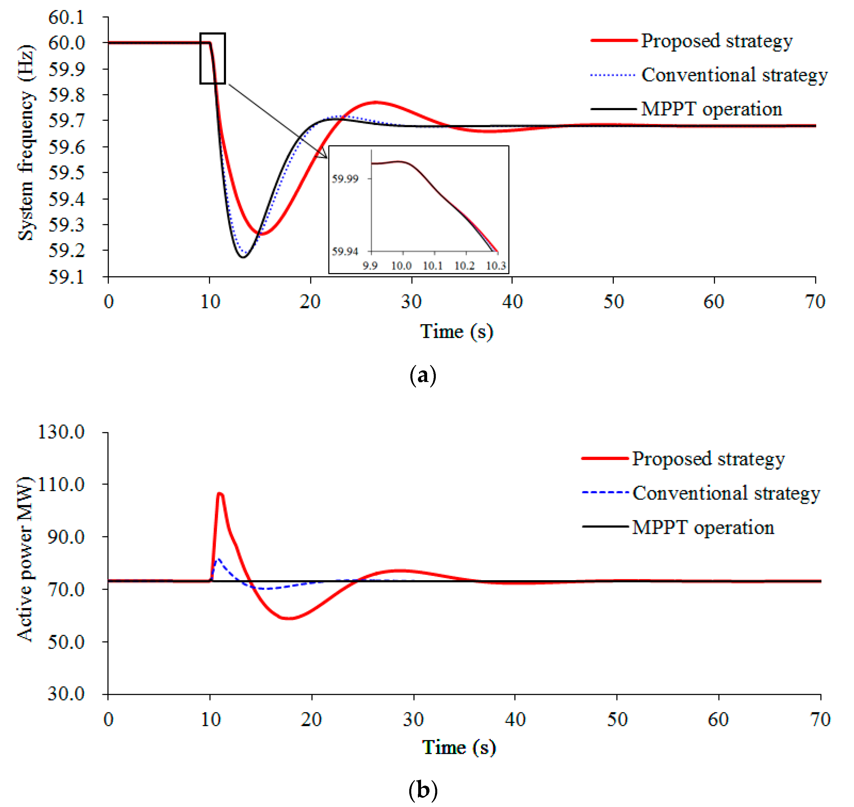
Figure 8 displays the simulation results, where the wind speed condition of the DFIG-based WTG is 10.0 m/s (partial load case). Thus, the kinetic energy available from the DFIG-based WTG is 3.96 s, which is 74% that of the total kinetic energy available. In this case, the pitch angle controller is not activated due to the lower wind speed.
The maximum df/dt in the proposed strategy, the conventional strategy, and the MPPT operation are –0.390 Hz/s, −0.475 Hz/s, and –0.503 Hz/s, respectively (see Figure 8a). The frequency nadirs in the MPPT operation, the conventional strategy, and the proposed strategy are 59.174 Hz, 59.194 Hz, and 59.265 Hz, respectively. In the MPPT operation, no power is injected to the grid, an as a result, there is no change in the rotor speed. For the conventional strategy, a small amount of power is injected to the power gird so that the rotor speed reduces, and the performances in terms of the system frequency nadir and the maximum df/dt are better than those of the MPPT operation. In the proposed strategy, a large amount of active power is injected to the power grid due to the proposed control gain in (13); as a result, the reduction in the rotor speed is large, and the performances of the frequency nadir and the maximum df/dt are better than the conventional strategy (see in Figure 8b,c).
Furthermore, the nadir-based frequency response of the proposed strategy is 122.45 MW/Hz, which is more than in the conventional strategy by 10.82 MW/Hz and more than that of the MPPT operation by 13.49 MW/Hz. This is because of the high frequency nadir. As displayed in Figure 8c and Table 4, the released kinetic energy from the DFIG-based WTG in the proposed method is 0.563 s, which is more than that of the conventional method by 0.422 s due to the large control gain in the proposed strategy.
6.2. Case 2: Wind Speed = 8.0 m/s
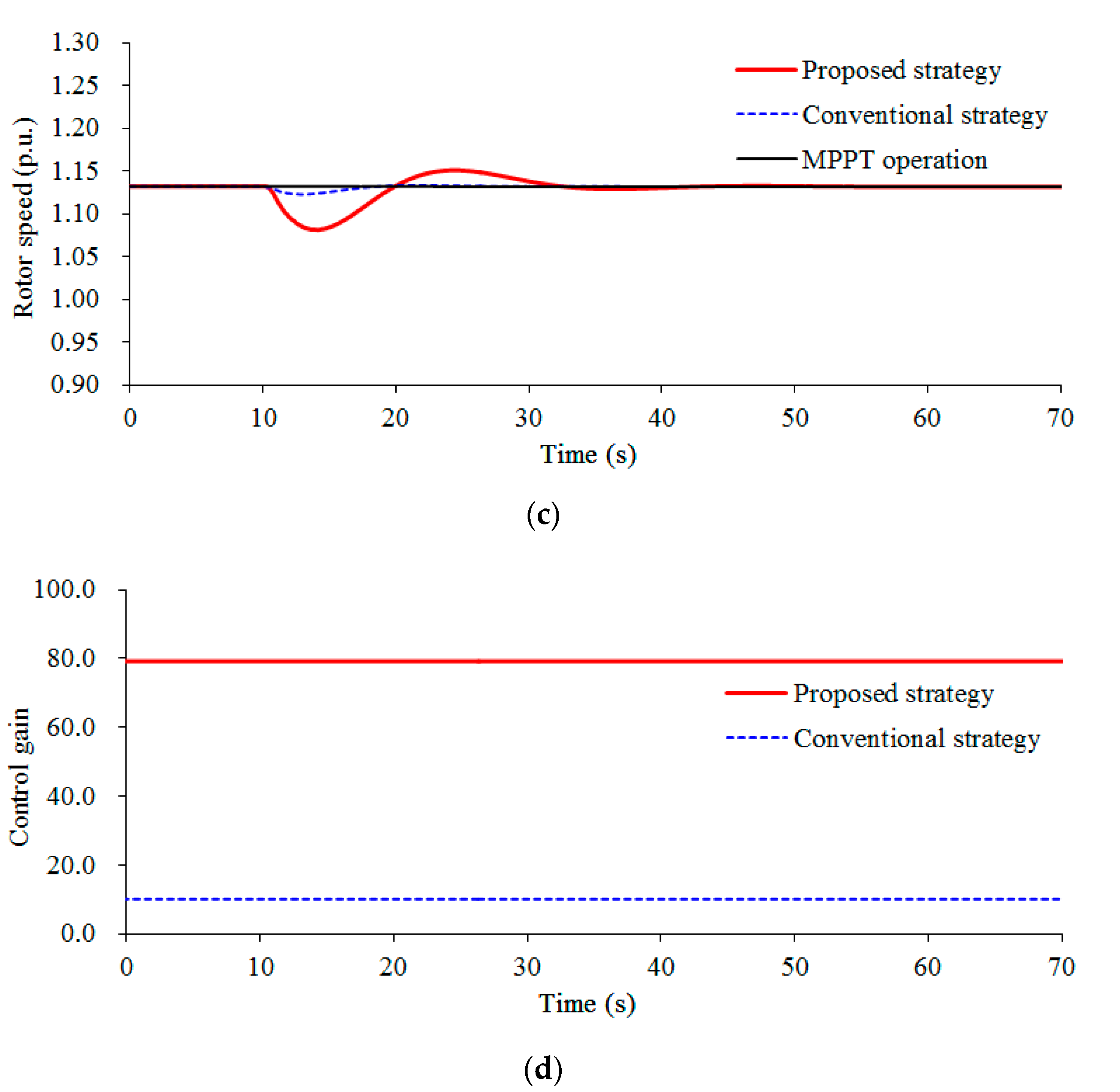
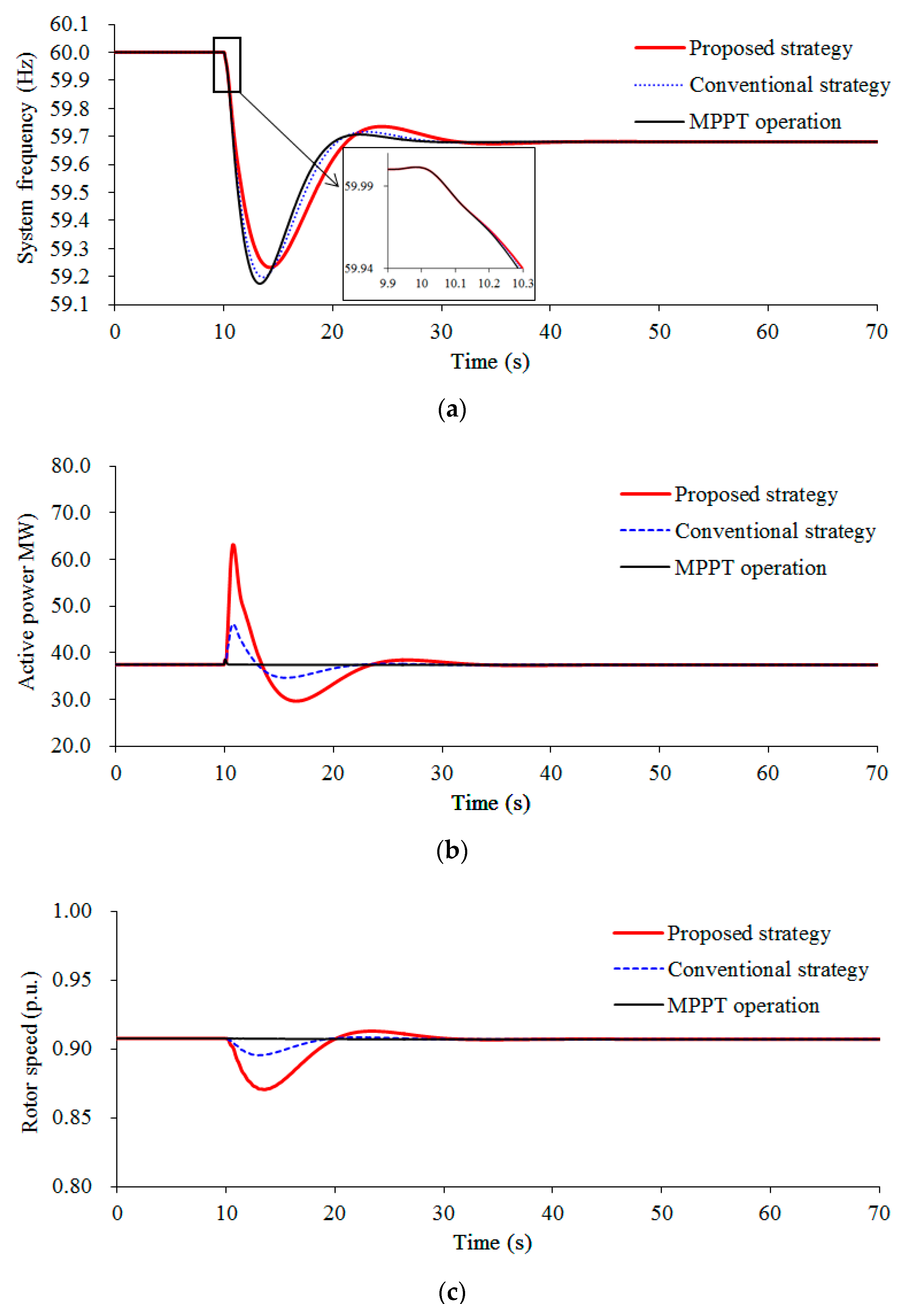
Figure 9 displays the simulation results, where the wind speed condition of the DFIG-based WTG is 8.0 m/s (partial load case). Thus, the kinetic energy available from the DFIG-based WTG is 1.66 s, which is 30% that of the total releasable kinetic energy and is 42% of the available kinetic energy in Case 2.
The maximum df/dt for the proposed strategy is –0.421 Hz/s, which is smaller than those of the conventional strategy and the MPPT operation by 0.055 Hz/s and 0.084 Hz/s, respectively. The frequency nadir for the proposed strategy is 59.232 Hz, which is more than those of the conventional strategy and the MPPT operation by 0.036 Hz and 0.057 Hz, respectively (see Figure 9a). Comparing the results to Case 1, the performances of frequency nadir and the maximum df/dt in the MPPT operation are almost the same as in Case 1, because the power injection is from synchronous generators. The performances of frequency nadir and the maximum df/dt in the conventional strategy are the same as in Case 1 due to the same control gain of virtual inertia control. The performances of the frequency nadir and the maximum df/dt for the proposed strategy are less than that of Case 1 because of the smaller control gain, as displayed in Figure 8 and Figure 9.
Further, as in Case 1, the proposed method ensures better nadir-based frequency response, which is more than those of the conventional method and the MPPT operation by 5.25 MW/Hz and 8.1 MW/Hz, respectively. The kinetic energy released for the proposed virtual inertia control strategy is more than that of the conventional strategy by 0.221 s. In addition, the kinetic energy released for the conventional method in Case 2 is the same as in Case 1 due to the same control gain.
6.3. Case 3: Wind Speed = 13.0 m/s
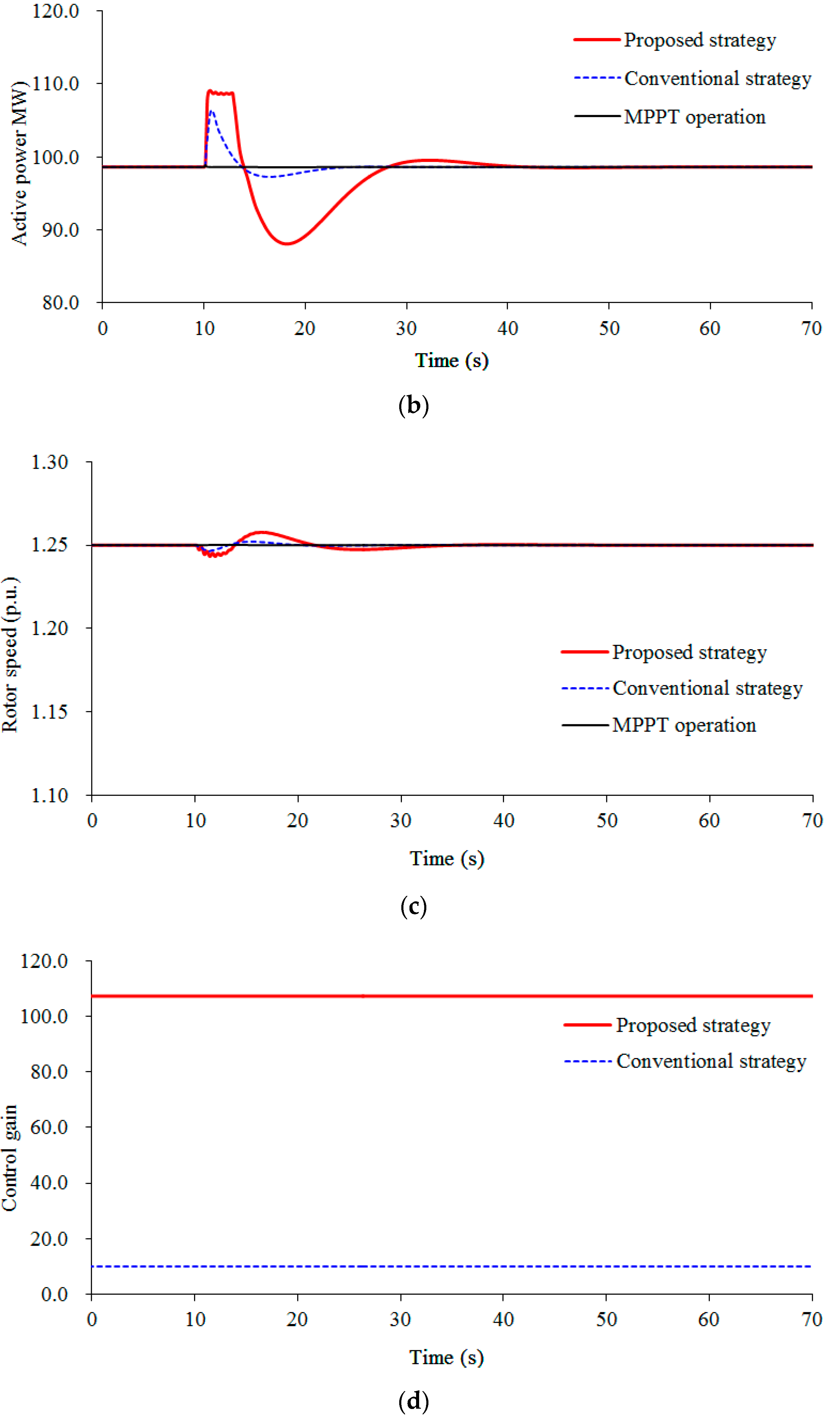
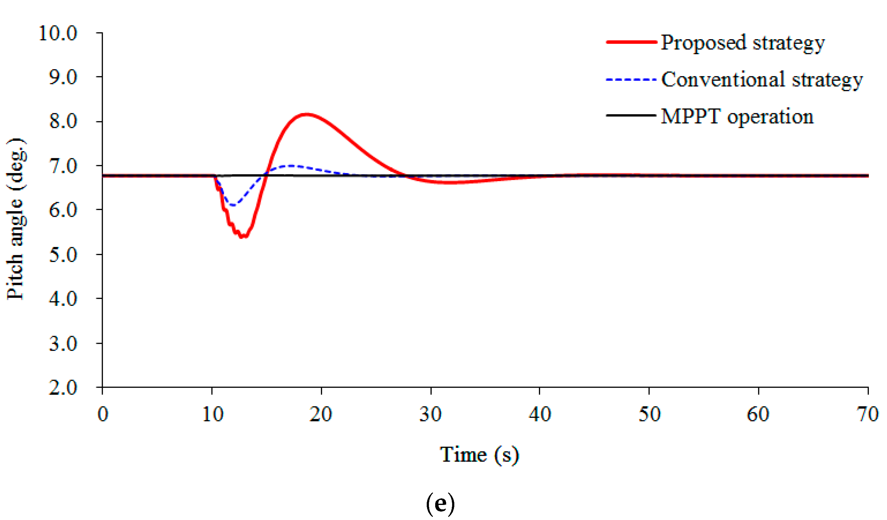
Figure 10 displays the simulation results, where the wind speed condition of the DFIG-based WTG is 13.0 m/s (full load case). In this case, the wind speed is greater than the rated wind speed so that the pitch angle controller is activated.
The maximum df/dt in the proposed strategy is –0.388 Hz/s, which is better than that of the conventional strategy and the MPPT operation (see Figure 10a). The frequency nadir in the proposed strategy is 59.267 Hz, which is greater than that of the conventional strategy and the MPPT operation by 0.650 Hz and 0.090 Hz, respectively. In the proposed strategy, a large amount of active power is injected to the power grid due to the proposed control gain in (13); as a result, the reduction in the rotor speed is large, and further, the large rotor speed deviation results in the large reduction in the pitch angle due to the large control gain of the proposed strategy (see Figure 10e). Consequently, the performances of the frequency nadir and the maximum df/dt are better than the conventional strategy (see in Figure 10b,c).
Furthermore, the nadir-based frequency response of the proposed strategy is 122.78 MW/Hz, which is more than in the conventional strategy by 9.72 MW/Hz and more than that of the MPPT operation by 13.42 MW/Hz. This is because of the high frequency nadir. As displayed in Figure 10c, the released kinetic energy from the DFIG-based WTG in the proposed method is 0.017 s, which is more than that of the conventional method by 0.007 s due to the large control gain in the proposed strategy. As shown in Figure 10e, the pitch angle of the proposed strategy decreases to 5.39°, whereas the pitch angle of the conventional strategy decreases to 6.11°.
The above simulation results display that the suggested virtual inertia control strategy is capable of ensuring better performance on the maximum df/dt and the frequency nadir by using the kinetic energy-dependent control gain under the scenarios of full and partial loads.
7. Conclusions
This study addresses a virtual inertia control strategy from the DFIG-based WTG to increase the frequency stability without causing the rotor speed stall. To accomplish this, a kinetic energy-dependent control virtual inertia control gain is proposed.
Simulation studies indicate that the suggested virtual inertia control strategy can increase the frequency stability more than that in the conventional strategy by releasing more kinetic energy from the DFIG-based WTG under the scenarios of full and partial loads. Moreover, the proposed control strategy can prevent the wind turbine from stalling, even when a large control gain is used.
The advantages of the proposed virtual inertia control method are that the control gain varies with the wind speed conditions. The virtual inertia control factor is used to regulate the performance of the frequency stability. Further, the control gain reduces with the wind speed and is zero at the minimum rotor speed so that the proposed strategy is capable of preventing the DFIG-based WTG from stalling, thereby avoiding the rotor speed security issue.
Author Contributions
D.Y., E.J., and L.H. mainly proposed the methodology of this paper. D.Y. and J.Y. carried out the simulation test. Writing, reviewing and editing were done by all the authors. All authors have read and agreed to the published version of the manuscript.
Funding
This work was supported by the Application research program of Nantong City (JC2019092), Key project of smart grid technology and equipment of national key research and development plan of China (2016YFB0900601).
Conflicts of Interest
The authors declare no conflict of interest.
References
- Bevrani, H. Robust Power System Frequency Control, 2nd ed.; Springer: New York, NY, USA, 2014. [Google Scholar]
- Ackermann, T. Wind Power in Power Systems, 2nd ed.; John Wiley & Sons, Ltd.: Chichester, UK, 2012. [Google Scholar]
- Chen, Z.; Guerrero, J.M.; Blaabjerg, F. A review of the state of the art of power electronics for wind turbines. IEEE Trans. Power Electron. 2009, 24, 1859–1875. [Google Scholar] [CrossRef]
- Yang, D.; Gao, H.-C.; Zhang, L.; Zheng, T.; Hua, L.; Zhang, X. Short-term frequency support of a doubly-fed induction generator based on an adaptive power reference function. Int. J. Electr. Power Energy Syst. 2020, 119, 1–10. [Google Scholar] [CrossRef]
- Kim, J.; Muljadi, E.; Gevorgian, V.; Hoke, A. Dynamic capabilities of an energy storage-embedded DFIG system. IEEE Trans. Ind. Appl. 2019, 55, 5119–5127. [Google Scholar] [CrossRef]
- Concordia, C.; Fink, L.H.; Poullikkas, G. Load shedding on an isolated system. IEEE Trans. Power Syst. 1995, 10, 1467–1472. [Google Scholar] [CrossRef]
- Yang, D.; Kim, J.; Kang, Y.C.; Muljadi, E.; Zhang, N.; Hong, J.; Song, S.H.; Zheng, T. Temporary frequency support of a DFIG for high wind power penetration. IEEE Trans. Power Syst. 2018, 33, 3428–3437. [Google Scholar] [CrossRef]
- EirGrid. A Proposal for Rate of Change of Frequency Remuneration Mechanism Recommendations; EirGrid: Dublin, Ireland, 2016. [Google Scholar]
- ENTSO-E. Requirements for grid connection applicable to all generators. In European Network of Transmission System Operators for Electricity; ENTSO-E: Brussels, Belgium, 2013. [Google Scholar]
- Keung, P.-K.; Li, P.; Banakar, H.; Ooi, B.T. Kinetic energy of wind-turbine generators for system frequency support. IEEE Trans. Power Syst. 2019, 24, 279–287. [Google Scholar] [CrossRef]
- Xue, Y.; Tai, N. Review of contribution to frequency control through variable speed wind turbine. Renew. Energy 2011, 36, 1671–1677. [Google Scholar]
- Fu, Y.; Zhang, X.; Hei, Y.; Wang, H. Active participation of variable speed wind turbine in inertial and primary frequency regulations. Electr. Power Syst. Res. 2017, 147, 174–184. [Google Scholar] [CrossRef]
- Liu, T.; Pan, W.; Quan, R.; Liu, M. A variable droop frequency control strategy for wind farms that considers optimal rotor kinetic energy. IEEE Access 2019, 7, 68636–68645. [Google Scholar] [CrossRef]
- Morren, J.; Pierik, J.; De Haan, S.W. Inertial response of variable speed wind turbines. Electr. Power Syst. Res. 2006, 76, 980–987. [Google Scholar] [CrossRef]
- Ekanayake, J.; Jenkins, N. Comparison of the response of doubly fed and fixed-speed induction generator wind turbines to changes in network frequency. IEEE Trans. Energy Convers. 2004, 19, 800–802. [Google Scholar] [CrossRef]
- Kim, J.; Muljadi, E.; Gevorgian, V.; Mohanpurkar, M.; Luo, Y.; Hovsapian, R.; Koritarov, V. Capability-coordinated frequency control scheme of a virtual power plant with renewable energy sources. IET Gener. Transm. Distrib. 2019, 13, 3642–3648. [Google Scholar] [CrossRef]
- Lorenzo, Z.; Andreas, J.R.; Janus, M.-S.; Ioannis, M.; Anca, D.H.; Poul, S. Virtual inertia for variable speed wind turbines. Wind Energy 2013, 16, 1225–1239. [Google Scholar]
- Lee, H.; Kim, J.; Hur, D.; Kang, Y.C. Inertial control of a DFIG-based wind power plant using the maximum rate of change of frequency and the frequency deviation. J. Electr. Eng. Technol. 2015, 10, 496–503. [Google Scholar] [CrossRef] [Green Version]
- Wu, L.; Infield, D.G. Towards an Assessment of Power System Frequency Support from Wind Plant—Modeling Aggregate Inertial Response. IEEE Trans. Power Syst. 2013, 28, 2283–2291. [Google Scholar] [CrossRef]
- Bonfiglio, A.; Invernizzi, M.; Labella, A.; Procopio, R. Design and Implementation of a Variable Synthetic Inertia Controller for Wind Turbine Generators. IEEE Trans. Power Syst. 2019, 31, 754–764. [Google Scholar] [CrossRef]
- Machowski, J.; Bialek, J.W.; Bumby, J.R. Frequency stability and control. In Power System Dynamics: Stability and Control, 2nd ed.; John Wiley & Sons, Ltd.: Wiltshire, UK, 2008. [Google Scholar]
- Ajjarapu, V.; McCalley, J.D.; Rover, D.; Wang, Z.; Wu, Z. Novel Sensorless Generator Control and Grid Fault Ride-through Strategies for Variable-Speed Wind Turbines and Implementation on a New Real-Time Simulation Platform. Ph.D. Dissertation, Department of Electrical Engineering, Iowa State University, Ames, Iowa, 2010. [Google Scholar]
- Boukhezzar, B.; Siguerdidjane, H. Nonlinear control of a variable speed wind turbine using a two mass model. IEEE Trans. Energy Convers. 2011, 26, 149–161. [Google Scholar] [CrossRef]
- Hand, M.M. Variable-Speed Wind Turbine Controller Systematic Design Methodology: A Comparison of Non-Linear and Linear Model-Based Designs; NREL/TP-500-25540; National Renewable Energy Laboratory: Golden, CO, USA, 1999. [Google Scholar]
- Shen, B.; Mwinyiwiwa, B.; Zhang, Y.; Ooi, B.-T. Sensorless maximum power point tracking of wind by DFIG using rotor position phase lock loop (PLL). IEEE Trans. Power Electron. 2009, 24, 942–951. [Google Scholar] [CrossRef]
- Yoo, I.; Kang, Y.C.; Yang, D.; Kim, K.-H.; Park, J.-W. Power Smoothing of a Variable-Speed Wind Turbine Generator Based on a Two-Valued Control Gain. IEEE Trans. Sustain. Energy (Early Access) 2020. [Google Scholar] [CrossRef]
- Wang, Y.; Delille, G.; Bayem, H.; Guilaud, X.; Francois, B. High wind power penetration in isolated power systems—Assessment of wind inertial and primary frequency responses. IEEE Trans. Power Syst. 2013, 28, 2412–2420. [Google Scholar] [CrossRef]
- Byerly, R.T.; Aanstad, O.; Berry, D.H.; Dunlop, R.D.; Ewart, D.N.; Fox, B.M.; Johnson, L.H.; Tschappat, D.W. Dynamic models for steam and hydro turbines in power system studies. IEEE Trans. Power Appar. Syst. 1973, 92, 1904–1915. [Google Scholar]
- Eto, J.H. Use of Frequency Response Metrics to Assess the Planning and Operating Requirements for Reliable Integration of Variable Renewable Generation; Technology Report; Ernest Orlando Lawrence Berkeley National Laboratory: Berkeley, CA, USA, 2010. [Google Scholar]
Figure 1.
Typical configuration of the doubly-fed induction generator (DFIG)-based Doubly-fed induction generator (WTG).
Figure 1.
Typical configuration of the doubly-fed induction generator (DFIG)-based Doubly-fed induction generator (WTG).

Figure 2.
Pitch angle controller.

Figure 3.
Mechanical power curves and MPPT operation curve of a DFIG-based WTG.

Figure 4.
Influence of different control gains of the virtual inertia control strategy at the wind speed of 6.5 m/s: (a) system frequencies; (b) active powers; (c) rotor speeds.
Figure 4.
Influence of different control gains of the virtual inertia control strategy at the wind speed of 6.5 m/s: (a) system frequencies; (b) active powers; (c) rotor speeds.


Figure 5.
Proposed control gain of virtual inertia control at different rotor speeds when C = 100.

Figure 6.
Test system embedded a DFIG-based WTG.

Figure 7.
IEEEG1 model (type B).

Figure 8.
Results for Case 1: (a) system frequencies; (b) active powers; (c) rotor speeds; (d) control gains. MPPT: maximum power point tracking.
Figure 8.
Results for Case 1: (a) system frequencies; (b) active powers; (c) rotor speeds; (d) control gains. MPPT: maximum power point tracking.


Figure 9.
Results for Case 2: (a) system frequencies; (b) active powers; (c) rotor speeds; (d) control gains.
Figure 9.
Results for Case 2: (a) system frequencies; (b) active powers; (c) rotor speeds; (d) control gains.


Figure 10.
Results for Case 3: (a) system frequencies; (b) active powers; (c) rotor speeds; (d) control gains; (e) pitch angle.
Figure 10.
Results for Case 3: (a) system frequencies; (b) active powers; (c) rotor speeds; (d) control gains; (e) pitch angle.


Table 1.
Parameters of synchronous generators.
| Item | SG1/SG2 | SG3/SG4 | SG5/SG6 |
|---|---|---|---|
| Nominal Apparent Power (MVA) | 150 | 200 | 100 |
| Inertia Constant (s) | 4.0 | 5.0 | 4.3 |
Table 2.
Parameters of the DFIG-based WTG.
| Item | Values | Units |
|---|---|---|
| Nominal Stator Voltage | 2.3 | kV |
| Nominal Apparent Power | 5.5 | MVA |
| Nominal Active Power | 5.0 | MW |
| Magnetizing Reactance | 2.9 | p.u. |
| Stator Leakage Reactance | 0.18 | p.u. |
| Rotor Resistance | 0.016 | p.u. |
| Rotor Leakage Reactance | 0.16 | p.u. |
| Stator Resistance | 0.023 | p.u. |
| Inertia Constant | 5.0 | S |
| Stable Operating Range of ωr | 0.70–1.25 | p.u. |
| Rated, Cut-in, and Cut-out Speeds | 11, 4, and 25 | m/s |
Table 3.
Parameters of the IEEEG1 steam governor model.
| K | K1 | K2 | K3 | T1 | T2 | T3 |
|---|---|---|---|---|---|---|
| 20 | 0.3 | 0.4 | 0.3 | 0.1 | 1.0 | 0.25 |
| T4 | T5 | T6 | Uo | Uc | Pmax | Pmin |
| 0.3 | 10 | 0.4 | 0.1 | –0.2 | 1 | 0.4 |
Table 4.
Comparison of numerical results for three cases.
| Index | Strategies | Case 1 | Case 2 | Case 3 |
|---|---|---|---|---|
| Maximum rate of change of system frequency (Hz/s) | MPPT operation | –0.503 | –0.505 | –0.502 |
| Conventional strategy | –0.475 | –0.476 | –0.474 | |
| Proposed strategy | –0.390 | –0.421 | –0.388 | |
| Frequency nadir (Hz) | MPPT operation | 59.174 | 59.175 | 59.177 |
| Conventional strategy | 59.194 | 59.196 | 59.202 | |
| Proposed strategy | 59.265 | 59.232 | 59.267 | |
| Nadir-based frequency response (MW/Hz) | MPPT operation | 108.96 | 109.09 | 109.36 |
| Conventional strategy | 111.63 | 111.94 | 113.07 | |
| Proposed strategy | 122.45 | 117.19 | 122.78 | |
| Released kinetic energy from the DFIG (s) | Conventional strategy | 0.108 | 0.108 | 0.010 |
| Proposed strategy | 0.563 | 0.329 | 0.017 |
© 2020 by the authors. Licensee MDPI, Basel, Switzerland. This article is an open access article distributed under the terms and conditions of the Creative Commons Attribution (CC BY) license (http://creativecommons.org/licenses/by/4.0/).
Share and Cite
MDPI and ACS Style
Yang, D.; Jin, E.; You, J.; Hua, L. Dynamic Frequency Support from a DFIG-Based Wind Turbine Generator via Virtual Inertia Control. Appl. Sci. 2020, 10, 3376. https://doi.org/10.3390/app10103376
AMA Style
Yang D, Jin E, You J, Hua L. Dynamic Frequency Support from a DFIG-Based Wind Turbine Generator via Virtual Inertia Control. Applied Sciences. 2020; 10(10):3376. https://doi.org/10.3390/app10103376
Chicago/Turabian StyleYang, Dejian, Enshu Jin, Jiahan You, and Liang Hua. 2020. "Dynamic Frequency Support from a DFIG-Based Wind Turbine Generator via Virtual Inertia Control" Applied Sciences 10, no. 10: 3376. https://doi.org/10.3390/app10103376
Note that from the first issue of 2016, this journal uses article numbers instead of page numbers. See further details here.