Improved Solar Operation Control for a Solar Cooling System of an IT Center


Institut für Energietechnik, Technische Universität Berlin, Marchstraße 18, 10587 Berlin, Germany
Appl. Sci. 2020, 10(10), 3354; https://doi.org/10.3390/app10103354
Submission received: 7 April 2020
/
Revised: 8 May 2020
/
Accepted: 10 May 2020
/
Published: 12 May 2020
(This article belongs to the Special Issue Solar Cooling Systems)
Abstract
:In this contribution, a model predictive control algorithm is developed, which allows an increase of the solar operating hours of a solar cooling system without a negative impact on the auxiliary electricity demand, e.g., for heat rejection in a dry cooler. An improved method of the characteristic equations for single-effect absorption chillers is used in combination with a simple dry-cooler model to describe the part load behavior of both components. The aim of the control strategy is to find a cut-in and a cut-off condition for the solar heat operation (SHO) of an absorption chiller cooling assembly (i.e., including all the supply pumps and the dry cooler) under the constraint that the specific electricity demand during SHO is lower than the electricity demand of a reference cooling technology (e.g., a compression chiller cooling assembly). Especially for the cut-in condition, the model predictive control algorithm calculates a minimum driving temperature, which has to be reached by the solar collector and storage in order to cover the cooling load with a low cooling water temperature but restricted auxiliary electricity demand. Measurements at a solar cooling system for an IT center were used for the testing and a first evaluation of the control algorithm.
1. Introduction
Worldwide, an increase of the cooling demand is expected. In the building sector, the cooling demand is the most rapidly increasing effective energy demand [1]. Usually, the cold generation is realized by electrically driven compression chillers. Hence, the expected development in effective energy demand will lead to an increased power requirement as well. Acting on the assumptions of the World Energy Outlook [2], the global power requirements will increase by 60% between 2016 and 2040. Approximately 15% to 20% of this elevation will be caused by the cooling demand. Consequently, solar-assisted cooling systems (SAC systems) have a large potential to reduce the fossil fuel consumption related to non-regenerative power generation.
On the other hand, it has been shown (e.g., in [3]) that a minimum solar fraction is necessary for SAC systems in order to achieve a lower primary energy consumption than a conventional system using an electrically driven compression chiller. Henning et al. [3] illustrated that the system performance with regard to primary energy savings is improved when the COP of the thermally driven chiller increases, the solar fraction increases, and the specific electricity consumption of the auxiliary components like supply pumps and cooling tower etc. decreases.
For SAC systems with parallel backup heating, the achievable solar fraction is a question of the possible operating time with solar heat from the collector. Solar heat operation (SHO) can start earliest when the collector temperature is higher than a minimum driving temperature and has to end latest when the collector temperature drops below. Of course, additional temperature differences have to be taken into account (e.g., for a heat exchanger between the collector and storage, heat losses etc.). The minimum driving temperature depends on the cooling load as well as the capacity and part load behaviour of the chiller. Moreover, it depends on the possible cooling water temperature, which is limited by the dry or wet bulb temperature. Generally speaking, depends on the load and meteorological conditions as well as the technology used for the chiller and the reject heat device but not on the collector technology. Nevertheless, the collector technology (including storages and the connection to parallel or serial backup heating systems) has a large influence on the necessary preheating time (i.e., the period from sunrise until is reached and solar heat operation can start) and thereby influences the overall system performance [4].
Taking the heat capacity effects of the collector and installation, as well as heat losses to the surrounding into account, Izquierdo [5] determined a solar radiation threshold as an equivalent measure to the minimum driving temperature. For a small SAC system in Madrid, two different heat rejection technologies were compared for the same meteorological conditions. In comparison to a wet cooling tower, a dry cooler revealed approximately 12 K higher cooling water temperatures. This led to about 20 K higher driving temperatures in the collector circuit and reduced the possible operating time of the SAC system from 9 to 3 h. The preheating time increased from approximately 3 to 6 h.
The influence of heat capacity effects on the preheating time was investigated by Li [6] and Kohlenbach [7] as well. While Li used a separated smaller part of a partitioned hot water storage tank to reduce the preheating time, Kohlenbach applied different temperature nodes of the storage tank for the control of the chiller before, during, and after solar heat operation. In both references, a constant (i.e., load and weather independent) start-up temperature of = 75 and 60 °C was used.
In order to shorten the preheating time, which is necessary to achieve a desired solar collector outlet temperature and thereby enable a longer solar operation of a single-effect absorption chiller, Shirazi et al. [8] recommend a variable speed pump for the solar collector loop. A comparison of the simulation results to a constant flow strategy showed that the solar fraction can be increased by about 11% by the temperature control strategy. Shirazi et al. [8] concluded that the longer solar operating time of the chiller (which results from the higher collector temperature) is more important for achieving a high solar fraction than the reduced collector efficiency due to a higher collector temperature.
Comparably, Qu et al. [9] investigated a constant flow rate versus constant outlet temperature control by transient simulations of an SAC system with parabolic trough collectors and a double-effect absorption chiller. They also indicated that the constant temperature control reduces the preheating time in the morning by approximately one hour and extends the operating time of the chiller driven by solar energy by approximately half an hour in the afternoon.
To make low collector temperatures applicable, Clauß et al. [10] described a control strategy similar to the one mentioned in [11] but without the constraint of an overflowing evaporator. Clauß et al. [10] used a control strategy based on the characteristic equation method that determines the required cooling water temperature for a predetermined driving temperature (e.g., from the solar collector field) in order to match a certain cooling load and to maintain the chilled water set value. In addition, using the cooling water temperature as the manipulated variable offers the possibility to save electric power and also water—if a wet cooling tower is used—provided the available driving temperature from the collector is higher than necessary to cover the load. In this case, a higher cooling water temperature can be used, which reduces the electricity demand of the reject heat device.
Unfortunately, the characteristic equation applied by Clauß et al. [10] is valid only for the 10-kW absorption chiller under investigation (i.e., type suninverse). Furthermore, the external supply flow rates in hot, cooling, and chilled water circuit must agree with the nominal flow rates, because otherwise the slope and loss parameter in the characteristic equation would change. Moreover, Clauß et al. [10] did not report on the reverse applicability of the characteristic equation method, i.e., calculating a necessary driving temperature from a given cooling water temperature in order to keep the preheating time short.
In this contribution, a model predictive control algorithm is developed, which allows an increase of the solar operating hours of an SAC system by calculating the minimum possible driving temperature under the constraint of a maximum allowed auxiliary electricity demand to ensure a short preheating time. This new strategy utilizes an improved and more precise method of characteristic equations [12]. The computer code of the method is available in [13]. The same characteristic equation method is used to control the absorption chiller itself, irrespective of whether it is operated in a solar or conventional cooling system [14]. Since the chiller control is based on characteristic equations, it is called a CE controller. Nevertheless, the focus of this contribution is not on the absorption chiller control (which is done by the CE controller and is described, e.g., in [14,15]), but on the control of the switchover between solar and backup heat operation of the chiller in a solar cooling system. Hence, following a short description of the SAC system at the Federal Environment Agency in Dessau, Germany (which was used to test the switchover strategy), the improved characteristic equation method is explained only briefly. Afterwards, the model predictive control algorithm for the switchover strategy is derived. It combines the absorption chiller model with a simple dry-cooler model. Finally, the measured results of the strategy are shown and discussed.
2. Materials and Methods
2.1. Solar Assisted Cooling System
In Figure 1, a simplified process and instrumentation diagram of the SAC system at the Federal Environment Agency (UBA) in Dessau, Germany with five heating circuits and four cooling circuits, each combined into one symbol, is depicted. The cold demand is dominated by the cooling circuit of the IT center with an average cooling load of approximately 20–25 kW around the clock. During summertime, the absorption chiller is powered either by district heat from a central CHP plant or by solar heat from a field of vacuum heat pipe collectors (216 m2 absorber area, 3 × 7.5 m3 storage volume). The idea of the relatively large storage volume and collector field with respect to the cooling load is to accumulate solar heat during daytime in order to cover the cooling load by solar heat operation of the absorption chiller during nighttime as well. The design values of the absorption chiller are provided in Table 1.
A compression-type chiller is used for the peak load and as redundancy for the IT center. During wintertime, solar heat is used for space heating and the reject heat device (RHD) is used directly for the cold supply. In this case, neither the compression-type chiller nor the absorption chiller is running. Nominal values of the reject heat device in dry-cooler mode are provided in Table 2. A more detailed description of the seasonal solar cooling concept can be found in [16].
2.2. Operating Period with High Solar Fraction
During summertime, two operating modes are possible for the absorption chiller:
- Solar heat operation (SHO); and
- Backup heat operation (BHO).
Independent of BHO or SHO, the thermally driven absorption chiller (TDC) is controlled by a model predictive controller based on an improved method of characteristic equations (the so-called CE controller). The CE controller calculates simultaneously the set values in hot and cooling water (i.e., and ), which are necessary to cover the cooling load . The CE controller is explained in more detail in [15] and in the next section.
In summer 2017, several tests were executed in order to extend the duration of SHO and thereby increase the solar fraction and primary energy saving of the SAC system. One of these test periods is depicted in Figure 2, where the cut-in condition for SHO was left unchanged but the cut-off condition was blocked manually in order to maximize the solar fraction.
SHO started on the first day when and the difference was smaller than 3 K for at least 5 min, which was true at approximately 10:30 (cf. Figure 1 for the sensor position and Figure 3 for their chronological progression). At first glance, this condition looks strange because the storage temperature was lower than the necessary driving temperature to cover the cooling load (i.e., the storage was still not hot enough). However, the temperature available for the chiller is a mixture of and (cf. Figure 1). Hence, the existing cut-in condition for SHO mentioned above (i.e., without the switchover strategy explained later on) is a compromise of , which was true at 10:00 a.m., and , which was true at 11:50 a.m. When the cut-in condition became true, the flap near the solar heat storages was opened by the control signal and the flaps near to the district heating heat exchanger were closed. Afterwards, the discharge pump P35 was switched on and the measured discharge flow rate was used to supply the absorption chiller with solar heat. The other curves in Figure 3 will be explained later.
The examined solar heat operation period was ongoing over more than three days (cf. in Figure 2b). Despite the volatile solar irradiation and the resulting volatile driving temperature for the chiller, it was possible to control the evaporator outlet temperature with a deviation to the set value of less than ±0.5 K (cf. Figure 2c) by means of the CE controller.
Although the flow rates of the absorption chiller were not automatically controlled, they were not constant (cf. Figure 2b). The variation of is an unwanted effect of hydraulic interdependencies between the discharge pump, heating circuits, and absorption chiller. Therefore, flow rates higher than the design value occurred. In contrast, the cooling water flow rate was adjusted manually (on the third day in order to avoid the humidifier activation, which was not successful, and afterwards to cover the load and keep the solar heat operation ongoing).
During normal operation (i.e., outside the test period for the high solar fraction), SHO is stopped when and the difference 0 K becomes true. Since this cut-off condition was deactivated during the test period, the desorber inlet temperature varied between approximately 85 and 50 °C and the cooling water inlet temperature to the absorber between 36 and 18 °C, respectively. To achieve these low cooling water temperatures in the reject heat device, the technical possibility to pre-cool the incoming ambient air by spraying water into the air flow (adiabatic evaporative pre-cooling) was allowed, although this operation mode is normally blocked due to high operating costs and hygienic aspects. By means of two short operating periods of the humidifier on the third day (cf. control signal of the humidifier in Figure 2a), a termination of SHO could be avoided.
However, independent of the adiabatic pre-cooling possibility, high air flow rates in the reject heat device were necessary when the storage temperatures were still low (e.g., in the morning) and/or ambient air temperature was high (cf. control signal for the ventilators in Figure 2a). Thus, the specific electricity demand of the solar thermally driven absorption chiller cooling assembly (ACCA) including the electricity demand of the thermally driven chiller (TDC), the supply pumps (Pu) and reject heat device (RHD):
became higher than the specific electricity demand of an electrically driven compression chiller cooling assembly (CCCA) also including the chiller itself, supply pumps, and the reject heat device. In this case, no primary energy saving was possible anymore and the solar heat operation should have been stopped. In Figure 2d, the instantaneous measured values of during the test period are compared to an averaged measured value of the air-cooled compression-type chiller (which was not in operation during the test period). During the first two nights, the continuous solar heat operation with low driving temperatures and consequently low cooling water temperatures led to values of that are lower than . Due to an increasing ambient air temperature, this does not apply for the whole third day. Consequently, to avoid values , an improved cut-off condition for SHO must take the specific electricity demand of the conventional or reference cooling assembly into account (in addition to the available solar driving temperature in the storage and the minimum driving temperature , which is necessary to cover the load under given weather conditions).
The ongoing of SHO on the fourth day, with low solar irradiation but relatively high ambient air temperature, was used to define the boundary. During the whole day, the storage temperature did not increase above 50 °C. Therefore, a tremendous effort of electricity and water was necessary to reach cooling water temperatures lower than 20 °C in order to cover the load. However, for all this, the possible cooling capacity was lower than the demand. Thus, in the evening, the evaporator outlet temperature did not match the set value anymore (cf. Figure 2c). At midnight of the fifth day, the solar heat operation (SHO) was stopped manually and the chiller was operated by district heating (BHO).
2.3. CE Method and CE Controller
The control strategy described in Section 3.2 to start the solar heat operation (SHO) of an SAC system as early as possible and to operate it in SHO mode as long as possible under the constraint of a maximum electricity demand necessitates a calculation procedure for the part load behavior of an absorption chiller. For this purpose, the characteristic equation method was applied.
In contrast to the characteristic equation method used by Clauß et al. [10], the method in this contribution is general for single-effect chillers [12]. By means of a revised heat transfer calculation in the absorber and desorber as compared to the established method (cf. [17]), the variation of thermodynamic losses under part load conditions can be accounted for in an explicit calculation procedure. According to the improved method, the cooling capacity of an absorption chiller is a linear function of a characteristic temperature difference :
The characteristic temperature difference combines the inlet temperatures (where holds for the main heat exchangers, desorber, evaporator, condenser, and absorber). The coefficients to in Equation (2) account for the phase equilibrium data of the respective working pair (i.e., ) in combination with the external and internal heat capacity flow rates and heat transfer capabilities . Hence, the characteristic temperature difference also includes all the information of the load-dependent and load-independent losses. The capacity of the chiller (i.e., its ‘thermal size’) is described by slope parameters and , respectively. Finally, the coefficient scales the minimum driving heat which results mainly from the limited internal heat recovery in the solution heat exchanger. The minimum driving heat is also not constant. It can be calculated with a second characteristic temperature difference , which is also a function of the independent external inlet temperatures and coefficients to [12]. The determining equations for all coefficients with can be found in [13] or [18]. For the absorption chiller at UBA, the values are depicted in Table 3 at the design conditions specified in Table 1.
Moreover, for control purposes, the external evaporator outlet temperature is of interest rather than . Instead of , a modified characteristic temperature difference can be derived analytically, which combines the hot and cooling water inlet temperature and chilled water outlet temperature:
Since the same coefficients to (with their respective physical meaning) are applied, a well-defined conversion factor is available to transform Equations (3) and (4) into Equations (7) and (8) for use with instead of . With the modified slope parameters and , the characteristic equations conform to:
In addition, for serial cooling water flow from the absorber to the condenser, the two characteristic temperature differences and are linked by the external thrust [12]:
Thus, with , the characteristic equation for the driving heat can be rewritten as:
A comparison of the measured and calculated values for the cooling capacity (i.e., and ) and driving heat (i.e., and ) is depicted in Figure 4a for the operating period discussed in Section 2.2. The same values are plotted as a function of in Figure 4b. Due to the variations in the hot and cooling water flow rate (cf. and in Figure 2b), the slope parameters and are not constant. Thus, neither the calculated values nor the measured values of the cooling capacity are displayed as a straight line. For the driving heat, a straight line was not to be expected at all (even at constant flow rates), because the temperature thrust will cause a scatter around the straight line given by and . An additional reason for the differences and scatter results from the dynamic operating conditions of the measurements in contrast to the calculated values, which assume steady state conditions by definition in the method. Nevertheless, the agreement of the measured and calculated values seems to be satisfying.
3. Results—Model Predictive Control
The model predictive control strategy for an extended solar heat operation of the SAC system combines the absorption chiller model (i.e., the improved characteristic equation method) with a part load model for the reject heat device. Since the combination of absorption chillers with dry coolers has become increasingly more common and the humidifier at the Federal Environment Agency in Dessau is normally blocked, a dry-cooler model is sufficient. After the description of the dry-cooler model, the control strategy is derived.
3.1. Dry-Cooler Model
In Figure 5, the nomenclature for the dry-cooler model is depicted. A control signal is used to adjust the air flow rate by changing the rotational speed of the ventilators or their motors, respectively. The necessary electrical power of the dry-cooler for a certain air flow rate is proportional to the pressure drop and total efficiency , including all mechanical and electrical losses of the motor-ventilator assembly. In addition, a constant auxiliary power consumption can be considered (e.g., for a control unit). Assuming a quadratic development of the air-side pressure drop with respect to the pressure drop under nominal conditions (i.e., ), this leads to:
which can be rewritten by expanding the fraction with as:
where is the normalised flow rate or the control signal of the dry cooler, respectively, and is the electrical power under nominal conditions.
The unknown air flow rate , which causes the electrical power, for a certain load condition, results from the reject heat flow of the absorption chiller from the absorber and condenser, . It is equivalent to the negative sum of the evaporator and desorber heat flow:
To determine (and thereby ), the required air outlet temperature in Equation (13) can be calculated from the dimensionless temperature glide, of the air stream, assuming a counter flow heat exchanger (i.e., neglecting all cross-counter flow effects):
The required cooling water inlet temperature of the dry-cooler on the left-hand side of Equation (14) is equal to the condenser outlet temperature, of the absorption chiller. It follows from the inlet temperature plus the temperature increase in the cooling water flow of the absorption chiller due to the total reject heat flow . Since the cooling water valve is used only for safety reasons, it is normally fully open. Consequently, for serial cooling water flow, the flow rates in the absorber and condenser and in the dry-cooler are the same, i.e., :
Combining Equations (14) and (15) results in:
and subsequently inserting Equation (16) into Equation (13) with the ambient air temperature as the air inlet temperature leads to:
However, Equation (17) determines only implicitly, because is a function of since the dimensionless heat transfer capability and heat capacity flow rate ratio in Equation (14) depend on :
In order to solve Equation (17) explicitly for , an approximation for the dimensionless temperature glide, is used from [12], appendix O:
In this equation, holds for the air side capacity flow rate at the nominal condition (Index 0) and is calculated with (i.e., also at the nominal condition). Thus, at the normalized flow velocity , the approximation equals (i.e., the exact value). For , Equation (19) converges to the same limit value as in Equation (14). Between and , the exponential dependency is considered by a reciprocal approach.
Inserting approximation Equation (19) into Equation (17) leads to an approximated but explicit equation for the air volume flow rate or the normalized flow velocity when constant property data can be assumed:
With determined, e.g., from manufacturers’ data under nominal conditions or from measurements at a single reference point, and the coefficients:
the approximated electrical power under the part load condition can be calculated:
A comparison between the measured and approximated values for the electrical power (i.e., and ) is depicted in Figure 4a for the operating period discussed in Section 2.2. without the humidification of ambient air.
3.2. Switchover Control Strategy
The aim of the following control strategy is to find a cut-in and a cut-off condition for the solar heat operation (SHO) of an absorption chiller cooling assembly (ACCA) under the constraint that the specific electricity demand during SHO is lower than the electricity demand of a reference cooling technology (e.g., a compression chiller cooling assembly, CCCA).
The specific electricity demand of the ACCA is dominated by the electricity demand of the dry cooler. Thus, a simplified cut-in condition for SHO is to allow a maximum control signal , which results in an approximated specific electricity demand lower or equal than the specific electricity demand of the compression chiller cooling assembly, i.e.:
Solving for the maximum allowed leads to the boundary value:
This depends on the reference cooling technology (), load condition (), and electrical values of the reject heat technology of the SAC system (, ). In addition, the control signal of the air flow rate for the same cooling load and the necessary driving heat flow according to the characteristic Equation (8) is determined by Equation (20), hence:
In this equation, only the supply temperatures and are unknown, because is fixed by the load and technology parameters according to Equation (25). On the right-hand side, in and are fixed by the load and weather condition and the coefficients , , and describe the thermal part load behaviour of the dry-cooler and absorption chiller.
The cooling water inlet temperature in Equation (26) can be eliminated by the rearranged characteristic Equation (7) in combination with the characteristic temperature in Equation (6), i.e.:
After inserting Equation (27) into Equation (26), it can be solved for the driving temperature , which is necessary for a cooling load at a chilled water temperature of and a maximum allowed control signal for the dry cooler in order to keep the specific electricity demand below when the absorption chiller is operated with solar heat:
where:
Finally, the operating limits of the absorption chiller have to be considered. For example, to avoid crystallization of the solution, a minimum cooling water temperature is allowed. Hence, from the rearranged characteristic Equation (7) follows a minimum driving temperature for the load case :
Consequently, the necessary driving temperature to start the solar heat operation is the maximum of the aforementioned temperatures:
The cut-in condition for solar heat operation (i.e., ) becomes true when the highest storage temperature and the outlet temperature of the solar heat exchanger are both higher than the necessary cut-in temperature for solar operation :
The cut-off condition for SHO consists of three aspects: Solar heat operation should be stopped when the highest temperature in the solar heat storage has decreased below the necessary driving temperature to cover the load or the necessary driving temperature for SHO, and simultaneously, the electricity demand becomes too high or the load cannot be matched anymore. Thus, the cut-off condition reads:
Typical values for the thresholds and are 2 and 0.2 K, respectively.
4. Discussion
The model predictive switchover strategy for extended solar heat operation (SHO) with improved cut-in and cut-off conditions has been implemented into the industrial programmable logic controller (PLC) of the single-stage -absorption chiller of type FM050v0.3 operated at the Federal Environment Agency (UBA) since 2011. Nowadays, this chiller is marketed as type “Bee” [19]. Via a Profi-Bus-connection, the information for the control signals of the flaps and is sent to the building management system, where it is put into execution. The switchover from BHO to SHO without a model-based cut-in condition is described in Figure 2. Now, the improved switchover strategy including a model-based cut-in/off condition is described. The measurements and overall results of the strategy are depicted in Figure 6 for an operating period of 2 days in September 2019. In Figure 7 and Figure 8, the cut-in and cut-off time periods are shown separately. On the first day, solar heat operation of the absorption chiller started at 11:00 a.m. and ended on the next day at approximately 08:00 a.m. Thus, the duration of the solar heat operation period is 21 h in comparison to 13 h of sunshine duration, i.e., from 06:30 a.m. until 07:30 p.m.
The driving temperature used in SHO started with approximately 67 °C, increased up to 78 °C in the afternoon of the first day, and decreased down to 49 °C in the morning of the next day. The corresponding cooling water temperatures of 25, 29, and 19 °C, which are necessary to cover the nearly constant cooling load of 23–29 kW0, were supplied by the heat rejection device in dry-cooler mode with a control signal of less the 60%. Accordingly, the mean specific electricity demand during the whole SHO period 0.18 kWel/kW0 is approximately 25% below the average specific electricity demand of the reference cooling technology 0.24 kWel/kW0 (cf. Figure 6d).
Inserting the electrical values = 13.5 kWel and = 1.7 kWel of the reject heat device at UBA into Equation (25) together with = 0.24 kWel/kW0 and the measured cooling load of about 23 to 29 kW0 leads to a maximum allowed control signal for the dry cooler of 0.66 to 0.73. Instead of this variable value, a constant value = 0.6 was used for test purposes. The resulting necessary driving temperature to start the solar heat operation of about 60 to 64 °C during the preheating time is plotted in Figure 7. At 10:50 a.m., the cut-in condition became true (cf. Equation (34) and in Figure 7) and a delay timer of 10 min was started. Since was true over the full delay period, the information for the control signal of the flap to be opened and of the flaps to be closed was sent to the building management system via Profi-Bus. Thus, at 11:00 a.m., solar operation started with a lower desorber inlet temperature 67 °C as before (i.e., 74 °C during BHO with district heating, cf. Figure 7). If the cut-in condition became false (i.e., ) during the delay period, the timer would have been reset to zero and restarted when had become true again. Thereby, a cut-in delay was realized.
Due to the lower driving temperature 67 °C (which is a mixed temperature of 70 °C from the solar heat exchanger and 65 °C from the storage), the set value for the cooling water was decreased by the CE controller for a while in order to match the cooling load and chilled water set value, . Therefore, the controller of the dry-cooler increased the control signal to adjust to (cf. Figure 6a). Shortly after 11 a.m., also increased above the cut-off value = 0.5 and the cut-off condition according to Equation (35) became true. Thus, for a definite result, and have to be used as set and reset inputs in a bistable function block.
With the rising ambient air temperature until 04:00 p.m., the necessary driving temperature also increases according to Equation (28). Since the available temperature from the solar collector and storage is high enough, SHO is ongoing. At nighttime, the available storage temperature falls below Nevertheless, the second part of the cut-off condition in Equation (35) is not true. Due to the low ambient air temperature, a low cooling water temperature is also available to counterbalance the low driving temperature. Thereby, the chilled water set value is still matched without an increase of the specific electricity demand (cf. Figure 6d). From approximately 06:30 a.m. of the second day on, the cooling water temperature is limited by the boundary value = 19 °C (cf. Figure 8). With a continuously decreasing driving temperature below 50 °C, the evaporator outlet temperature starts to increase and the cooling load is not matched anymore. Consequently, SHO has to be stopped approximately at 07:30 a.m.
The rapid increase of at approximately 7:45 a.m. is an effect of a switching action in one of the heating circuits, which causes a much lower hot water flow rate for some minutes. For flow rates close to zero, the slope coefficients and (i.e., the possible capacity of the chiller or its ‘thermal size’) become very small and consequently the necessary driving temperature high. Unfortunately, this interference happened in parallel or at the end of the cut-off delay for SHO. Nevertheless, it did not switch off the solar heat operation (although it looks like it) and did not have any effect on the end of SHO at all. The cut-off condition (cf. Equation (35) or in Figure 8) was true since 07:10 a.m. With the cut-off delay time of 20 min, SHO was stopped at 07:30 a.m. A very few minutes later (i.e., after communication between PLC and the building management system), the discharge pump P35 was switched off and the flow rate reached zero. Now, SHO also stopped hydraulically. Incidentally, at the same moment, increased after the short interruption.
The potential of the improved control strategy was illustrated by a theoretical application during the test period in 2017 (cf. Figure 2), when the cooling load was low during the preheating time in the morning of the first day (cf. Figure 3). Under these operating conditions, the cut-in condition would have become true before 10:00 a.m. and a necessary solar driving temperature below 65 °C at the outlet of the solar heat exchanger would have been sufficient to start SHO.
5. Conclusions
For solar cooling systems with an absorption chiller cooling assembly (i.e., including all the supply pumps and the heat rejection device), the possible operating time with solar heat is a key parameter to achieve high solar fractions and thereby high primary energy savings. Hence, for SAC systems, the solar heat operation (SHO) of the absorption chiller should be started as early as possible and should be continued as long as possible in order to reduce the backup heating demand, thereby reducing the main source of the primary energy demand. On the other hand, when the SHO mode is activated too early and/or stopped too late, the available driving temperature from solar collector is low. Consequently, a lower cooling water temperature is necessary to cover the cooling load. It depends on the part load behavior of the chiller and can be calculated by the characteristic equation method. The lower cooling water temperature causes a higher electricity demand in the reject heat device. These theoretical interdependencies were exemplified during a test period with continuous solar heat operation over more than three days at the SAC system of the Federal Environment Agency in Dessau, Germany. It was shown that the resulting electricity demand during solar heat operation might exceed the demand of the reference technology (e.g., a compression chiller cooling assembly) and no primary energy savings are possible anymore.
In order to extend the solar heat operation period on the one hand, and to ensure a specific electricity demand below a boundary value on the other hand, a model predictive switchover strategy was developed. The combination of an improved characteristic equation method for the part load behavior of absorption chillers with a simple dry-cooler model was used to find a suitable cut-in and cut-off condition for the solar heat operation. The two conditions depend on a minimum solar driving temperature, which has to be reached by the solar collector and storage before solar heat operation is enabled. The minimum driving temperature depends on technical coefficients describing the part load characteristics of the dry cooler and absorption chiller, and also on the load and weather conditions.
Measurements at a solar cooling system for an IT center with a cooling demand of approximately 20–30 kW0 around the clock showed that solar heat operation could be started with approximately 67 °C and was possible down to 49 °C. The duration of solar heat operation was 21 h in comparison to 13 h of sunshine duration, and the mean specific electricity demand during the whole SHO period was approximately 25% below the average specific electricity demand of the reference cooling technology.
Although the model predictive switchover strategy utilizes the same method of characteristic equations as the control algorithm of the relevant absorption chiller in the investigated SAC system, it is generally possible to apply the switchover strategy independent of the chiller control. In contrast to the state of the art, where constant (or at least load and weather independent) cut-in temperatures for solar heat operation are used, the new switchover strategy incorporates the actual load and weather condition as well as the part load capability of the absorption chiller and reject heat device. Thus, the new switchover strategy provides the cut-in temperature as a quality of the whole absorption chiller cooling assembly supplied by solar energy.
Funding
This research was funded by the Bundesministerium für Wirtschaft und Energie (BMWi), grant numbers 03ET1171A and 03ET1583.
Conflicts of Interest
The author declares no conflict of interest.
References
- IEA. Energy Technology Perspectives. 2017. Available online: https://www.iea.org/reports/energy-technology-perspectives-2017 (accessed on 27 February 2018).
- IEA. Space Cooling—More Access, More Comfort, Less Energy. 2017. Available online: https://www.iea.org/publications/freepublications/publication/SpaceCoolingEnergyEfficiencyInsightsBrief.pdf (accessed on 27 February 2018).
- Henning, H.-M. Solar-Assisted Air Conditioning in Buildings—A Handbook for Planners; Springer: Wien, Austria, 2004. [Google Scholar]
- Eicker, U.; Pietruschka, D. Design and performance of solar powered absorption cooling systems in office buildings. Energy Build. 2009, 41, 81–91. [Google Scholar] [CrossRef]
- Izquierdo, M.; Hernandez, F.; Martin, E. Solar cooling in Madrid: Available solar energy. Solar Energy 1994, 53, 431–443. [Google Scholar] [CrossRef]
- Li, Z.F.; Sumathy, K. Experimental studies on a solar powered air conditioning system with partitioned hot water storage tank. Solar Energy 2001, 71, 285–297. [Google Scholar] [CrossRef]
- Kohlenbach, P. Solar Cooling with Absorption Chiller—Control Strategies and Transient Chiller Performance. Ph.D. Thesis, Fakultät III Prozesswissenschaften, TU Berlin, Berlin, Germany, 2005. [Google Scholar]
- Shirazi, A.; Pintaldi, S.; White, S.D.; Morrison, G.L.; Rosengarten, G.; Taylor, R.A. Solar-assisted absorption air-conditioning systems in buildings: Control strategies and operational modes. Appl. Therm. Eng. 2016, 92, 246–260. [Google Scholar] [CrossRef]
- Qu, M.; Yin, H.; Archer, D.H. A solar thermal cooling and heating system for a building: Experimental and model based performance analysis and design. Solar Energy 2010, 84, 166–182. [Google Scholar] [CrossRef]
- Clauß, V.; Kühn, A.; Ziegler, F. A new control strategy for solar driven absorption chillers. In Proceedings of the 2nd International Conference Solar Air Conditioning, Paper ID 18, Tarragona, Spain, 18–19 October 2007. [Google Scholar]
- Albers, J.; Asdrubali, F.; Ziegler, F. Investigation into the influence of the cooling water temperature on the operating conditions of thermosyphon generators. In Proceedings of the International Sorption Heat Pump Conference, Paper ID 053, Denver, CO, USA, 22–24 June 2005. [Google Scholar]
- Albers, J. Enhancement of a calculation method for the control of absorption chillers. Ph.D. Thesis, Fakultät III Prozesswissenschaften, TU Berlin, Berlin, Germany, 2019. [Google Scholar]
- Albers, J. CE_Method. A MATLAB function for calculating the part load behaviour of absorption chillers and heat pumps based on (C)haracteristic (E)quations. 2017. Available online: https://www.depositonce.tu-berlin.de/handle/11303/6738 (accessed on 1 March 2020). [CrossRef]
- Petersen, S.; Albers, J.; Graf, R.; Hausherr, C.; Hennrich, C.; Hüls, W.; Hunt, S.; Lanser, W.; Paitazoglou, C.; Schröder, M.; et al. EnEff: Wärme—Feldtest Absorptionskälteanlagen für KWKK-Systeme. Final Report FKZ 03ET1171(A-D), TU Berlin, Inst. f. Energietechnik. 2019. Available online: https://www.tib.eu/de/suchen/id/TIBKAT%3A1666931608/Feldtest-Absorptionsk%C3%A4lteanlagen-f%C3%BCr-KWKK-Systeme/ (accessed on 11 May 2020).
- Albers, J.; Ziegler, F. Control Strategies for Absorption chillers in CHPC-plants ensuring low hot water return temperatures. In Proceedings of the Heat Powered Cycles Conference, Nottingham, UK, 27–29 June 2016. [Google Scholar]
- Albers, J. New absorption chiller and control strategy for the solar assisted cooling system at the German Federal Environment Agency. Int. J. Refrig. 2014, 39, 48–56. [Google Scholar] [CrossRef]
- Hellmann, H.M.; Schweigler, C.; Ziegler, F. The characteristic equations of absorption chillers. In Proceedings of the International Sorption Heat Pump Conference, Munich, Germany, 24–26 March 1999; pp. 169–172. [Google Scholar]
- Albers, J. Präzisierungen zur Methode der charakteristischen Gleichungen. In Proceedings of the Tagungsband Deutsche Klima-Kälte-Tagung, Paper ID: AA.II.1.15, Bremen, Germany, 22–24 November 2017. [Google Scholar] [CrossRef]
- BINE. Cooling with Heat—A New Generation of Compact Chillers Cools and Heats with Low-Temperature Heat. 2012. Available online: http://www.bine.info/fileadmin/content/Presse/Projektinfos_2012/Projekt_07-2012/ProjektInfo_0712_engl_internetx.pdf (accessed on 1 March 2020).
Figure 1.
Simplified process and instrumentation diagram of the SAC system at the Federal Environmental Agency (UBA) in Dessau, Germany. Only the temperature probes and flow meters that are used in the result section are labelled.
Figure 1.
Simplified process and instrumentation diagram of the SAC system at the Federal Environmental Agency (UBA) in Dessau, Germany. Only the temperature probes and flow meters that are used in the result section are labelled.
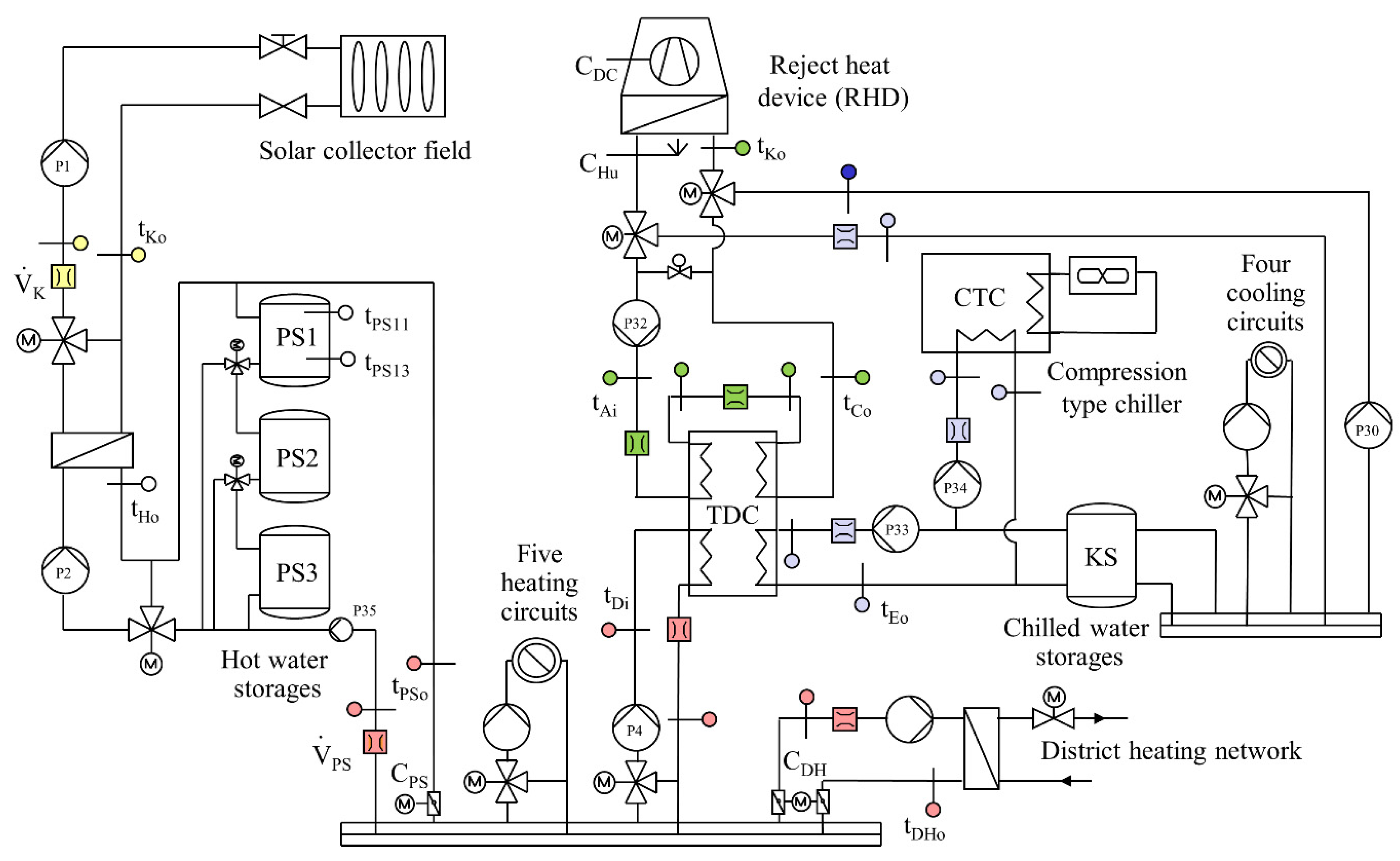
Figure 2.
Continuous solar heat operation extending over more than three days during a test period (i.e., without the improved control strategy): (a) global horizontal irradiation, , temperatures in the hot water circuit, and control signals from RHD; (b) flow rates and cooling capacity; (c) ambient air temperature and temperatures in the chilled and cooling water circuit; (d) specific electricity demand.
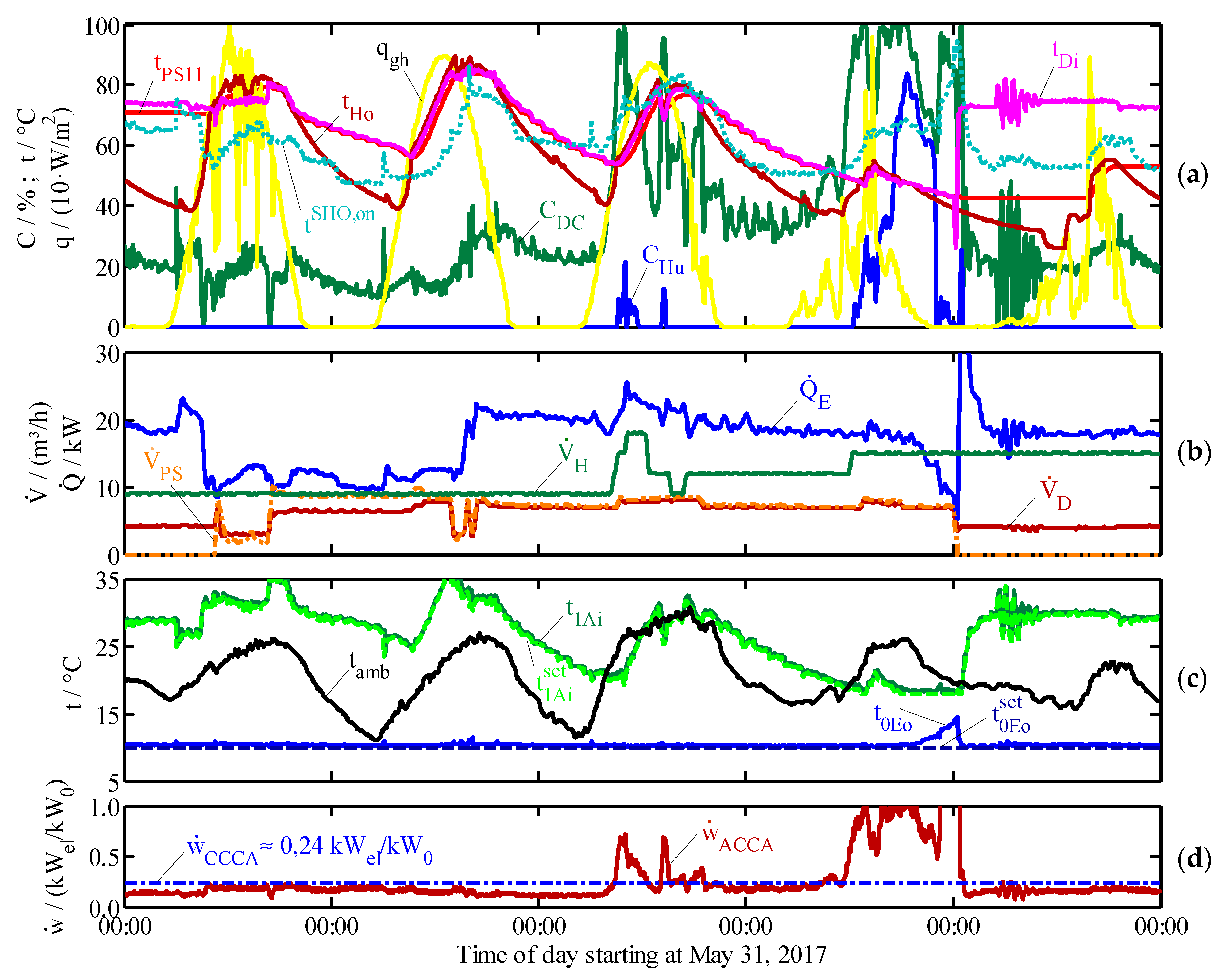
Figure 3.
Start-up period of solar heat operation (SHO) without the improved control strategy.

Figure 4.
Comparison of the measured and calculated values for the absorption chiller and dry-cooler model as a function of time (a) and for the absorption chiller as a function of the inlet characteristic temperature difference (b).
Figure 4.
Comparison of the measured and calculated values for the absorption chiller and dry-cooler model as a function of time (a) and for the absorption chiller as a function of the inlet characteristic temperature difference (b).
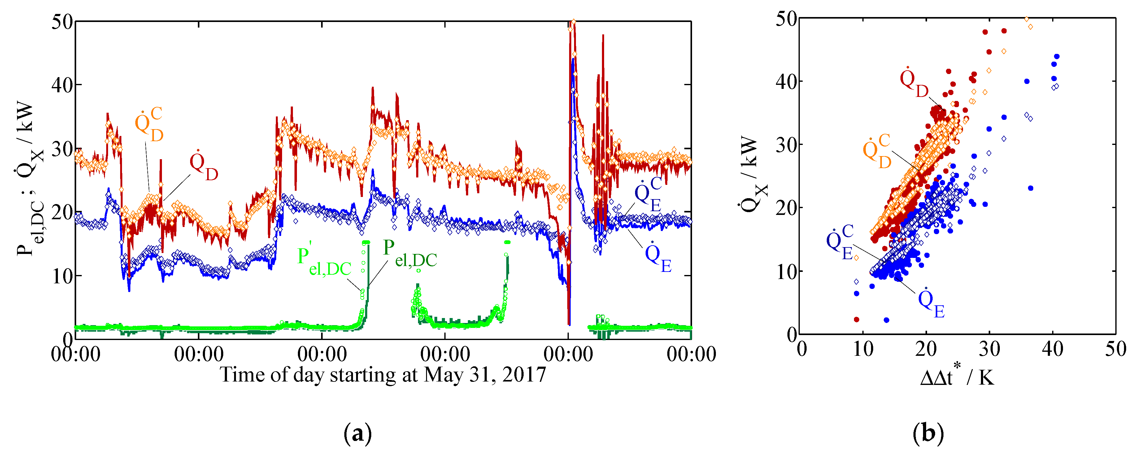
Figure 5.
Nomenclature for dry-cooler model.
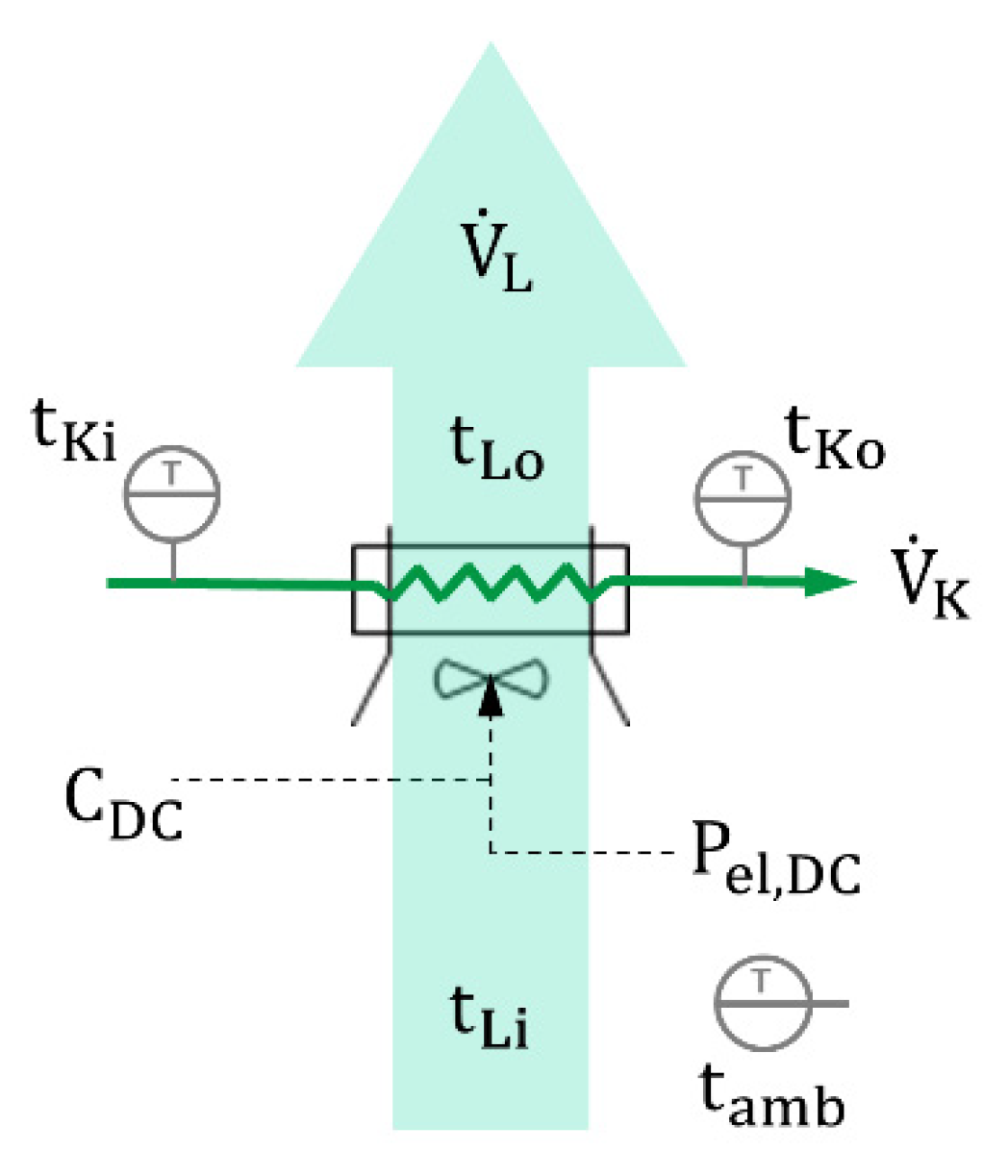
Figure 6.
Solar heat operation over 21 h with the improved control strategy: (a) global horizontal irradiation, , temperatures in hot water circuit and control signals from RHD; (b) flow rates and cooling capacity; (c) ambient air temperature and temperatures in the chilled and cooling water circuit; (d) specific electricity demand.
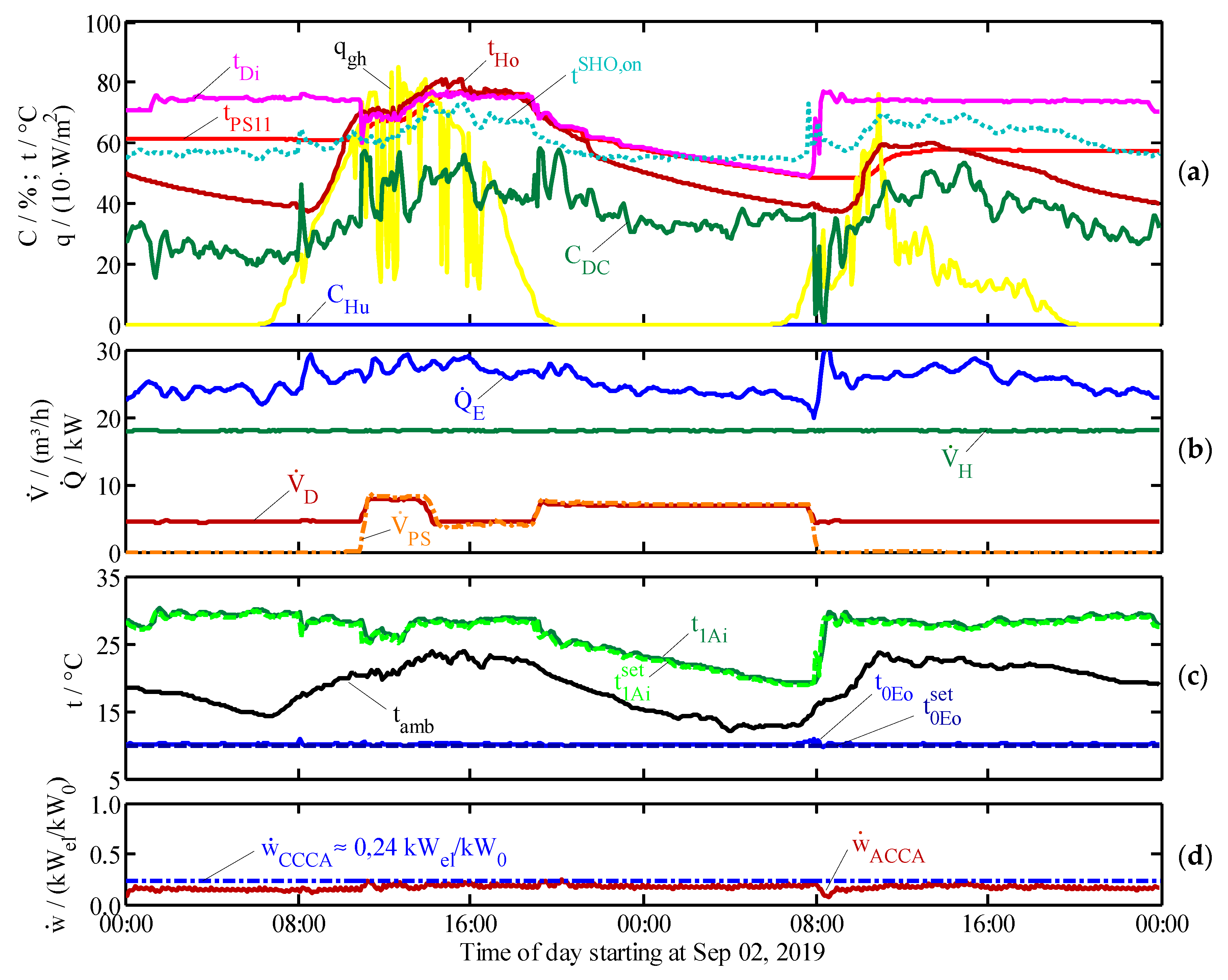
Figure 7.
Start-up of solar heat operation with the improved control strategy.
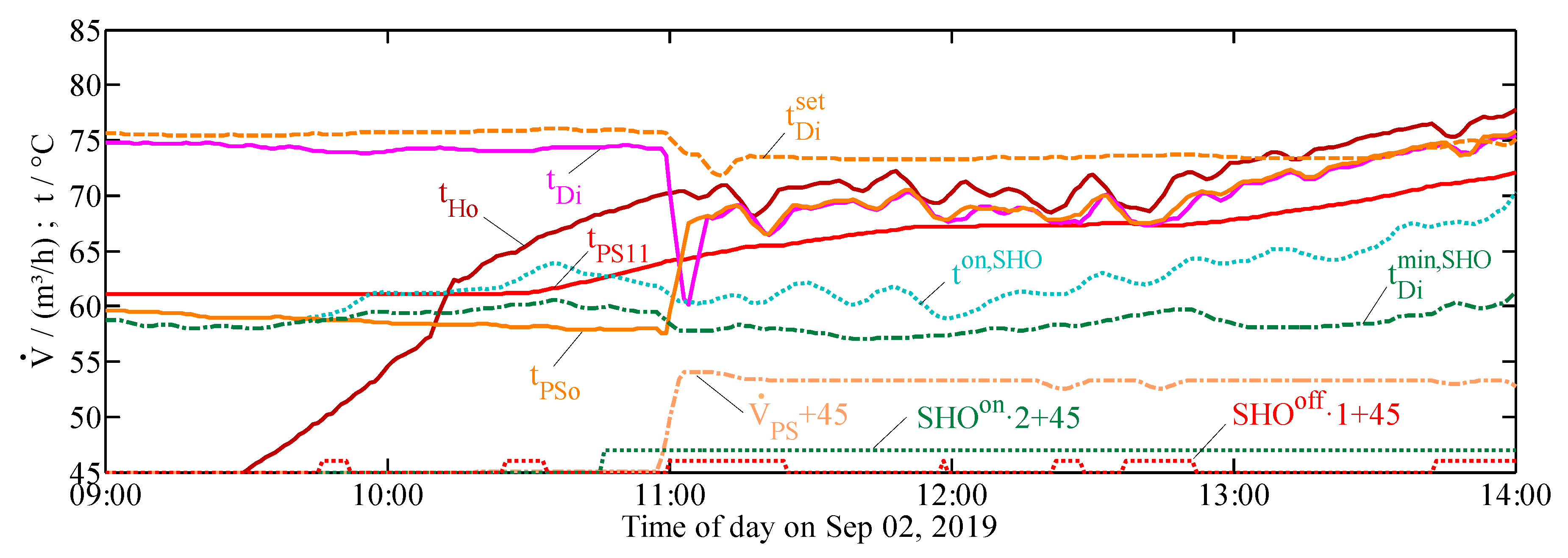
Figure 8.
Shutdown of solar heat operation with the improved control strategy.


Table 1.
Design values of the absorption chiller type FM050V0.3 at the Federal Environment Agency (UBA) in Dessau, Germany.
Table 1.
Design values of the absorption chiller type FM050V0.3 at the Federal Environment Agency (UBA) in Dessau, Germany.
| Variable | Description | Unit | FM050V0.3 |
|---|---|---|---|
| Hot water inlet temperature | °C | 75 | |
| Hot water volume flow rate | m3/h | 6.0 | |
| Driving heat flow | kW | 44 | |
| Cooling water inlet temperature | °C | 28 | |
| Cooling water volume flow rate | m3/h | 18.0 | |
| Reject heat flow | kW | 78 | |
| Chilled water outlet temperature | °C | 9 | |
| Chilled water volume flow rate | m3/h | 5.9 | |
| Cooling capacity | kW | 34 | |
| COP | Coefficient of performance | - | 0.77 |
Table 2.
Nominal values of the reject heat device in dry-cooler mode at the Federal Environment Agency (UBA) in Dessau, Germany.
Table 2.
Nominal values of the reject heat device in dry-cooler mode at the Federal Environment Agency (UBA) in Dessau, Germany.
| Variable | Description | Unit | Dry-Cooler |
|---|---|---|---|
| Fluid inlet temperature | °C | 32 | |
| Fluid outlet temperature | °C | 29 | |
| Fluid volume flow rate | m3/h | 45.5 | |
| Mass fraction ethylene-glycol | kg/kg | 0 | |
| Air inlet temperature | °C | 21 | |
| Air volume flow rate | m3/h | 45,940 | |
| Reject heat flow | kW | 158 | |
| Electrical power | kWel | 13.7 |
Table 3.
Characteristic coefficients of the absorption chiller at the Federal Environment Agency (UBA) in Dessau, Germany.
Table 3.
Characteristic coefficients of the absorption chiller at the Federal Environment Agency (UBA) in Dessau, Germany.
| Effective Coefficients (Dimensionless) | Slope Parameters (in kW/K) | Conversion Factor | ||||
|---|---|---|---|---|---|---|
| 0.07 | −1.02 | −0.09 | 1.20 | 1.45 | 0.15 | 1.23 |
© 2020 by the author. Licensee MDPI, Basel, Switzerland. This article is an open access article distributed under the terms and conditions of the Creative Commons Attribution (CC BY) license (http://creativecommons.org/licenses/by/4.0/).
Share and Cite
MDPI and ACS Style
Albers, J. Improved Solar Operation Control for a Solar Cooling System of an IT Center. Appl. Sci. 2020, 10, 3354. https://doi.org/10.3390/app10103354
AMA Style
Albers J. Improved Solar Operation Control for a Solar Cooling System of an IT Center. Applied Sciences. 2020; 10(10):3354. https://doi.org/10.3390/app10103354
Chicago/Turabian StyleAlbers, Jan. 2020. "Improved Solar Operation Control for a Solar Cooling System of an IT Center" Applied Sciences 10, no. 10: 3354. https://doi.org/10.3390/app10103354
Note that from the first issue of 2016, this journal uses article numbers instead of page numbers. See further details here.