Mechanical and Durability Properties of Concrete with Coarse Recycled Aggregate Produced with Electric Arc Furnace Slag Concrete


Abstract
1. Introduction
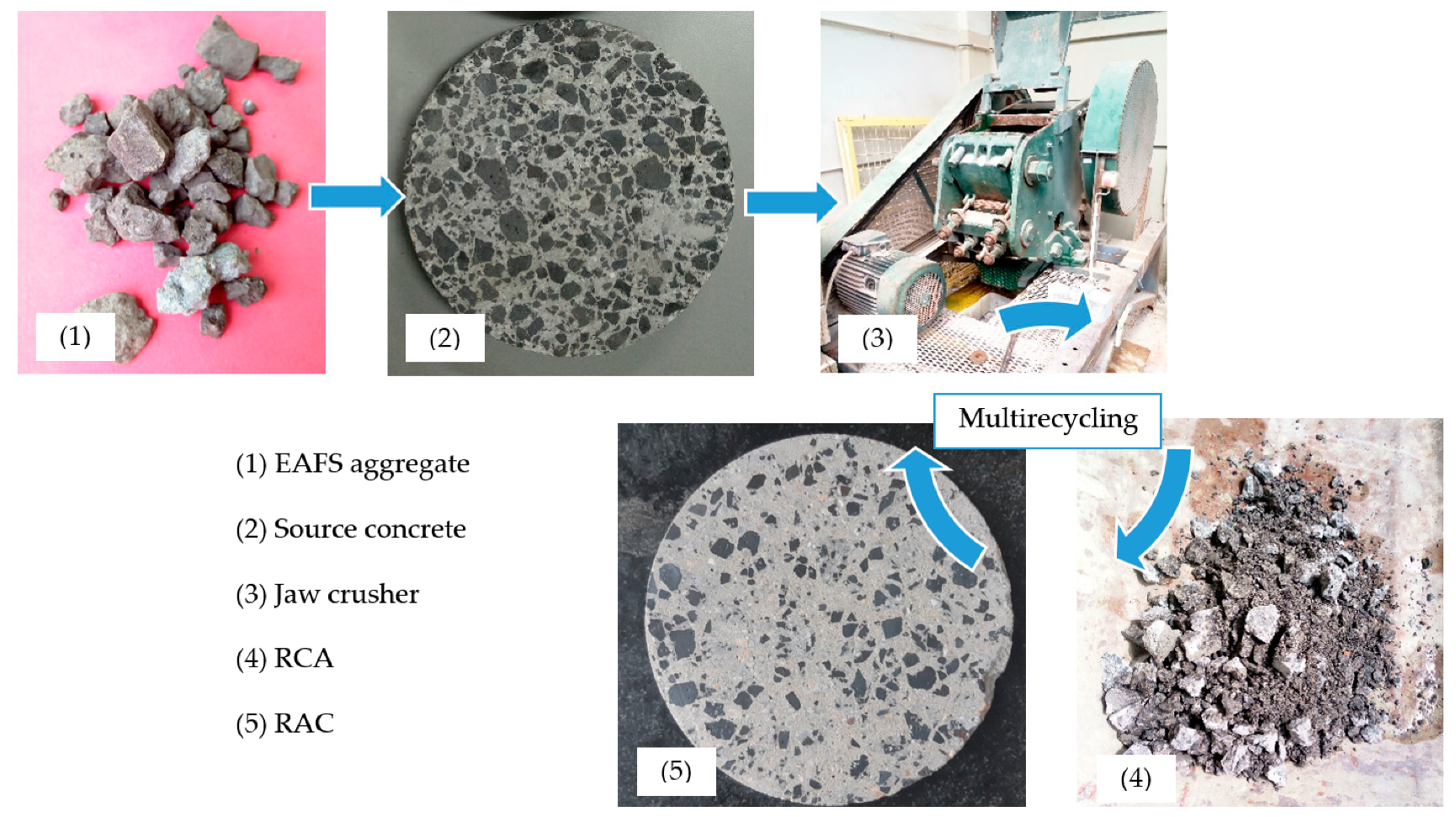
2. Materials and Methods
2.1. Materials
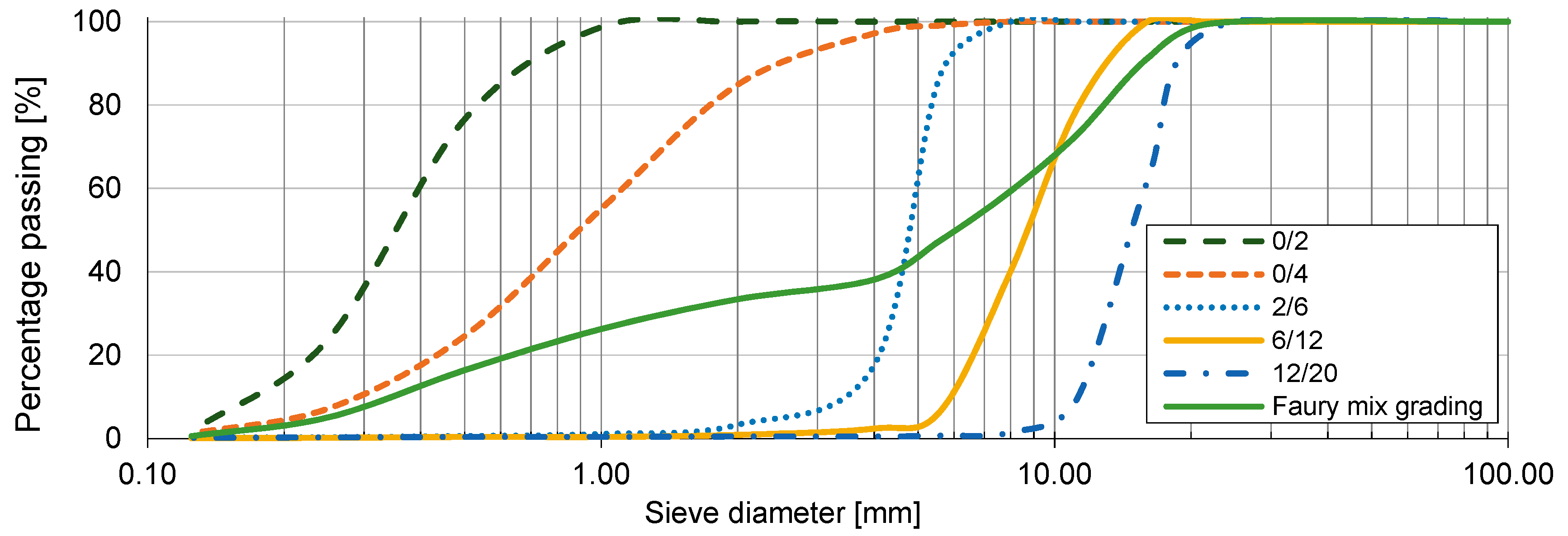
2.2. Mix Design
2.3. Physical Properties Tests
2.4. Mechanical Properties Tests
2.5. Durability Tests
3. Results and Discussion
3.1. Physical Properties
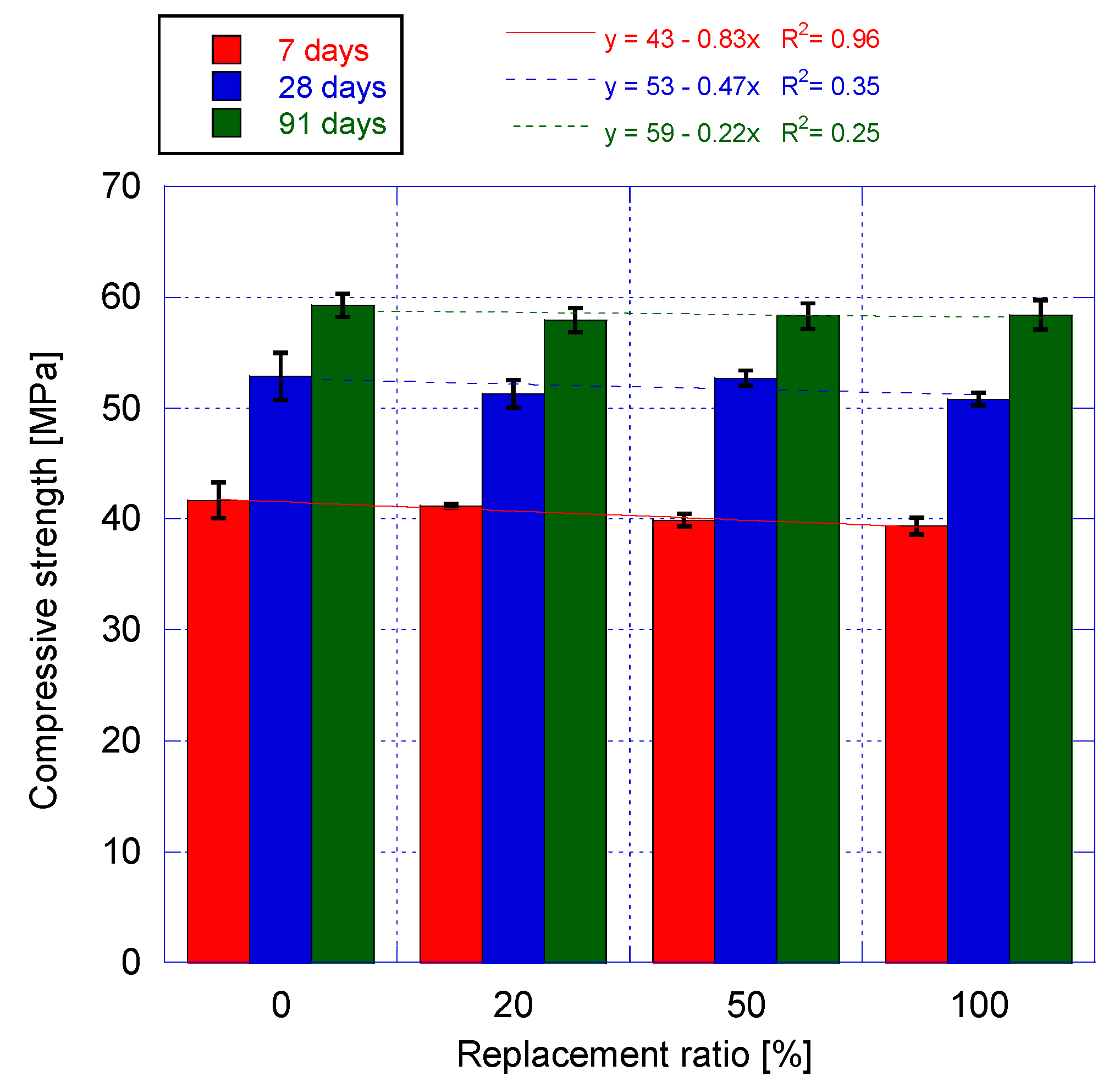
3.2. Mechanical Properties
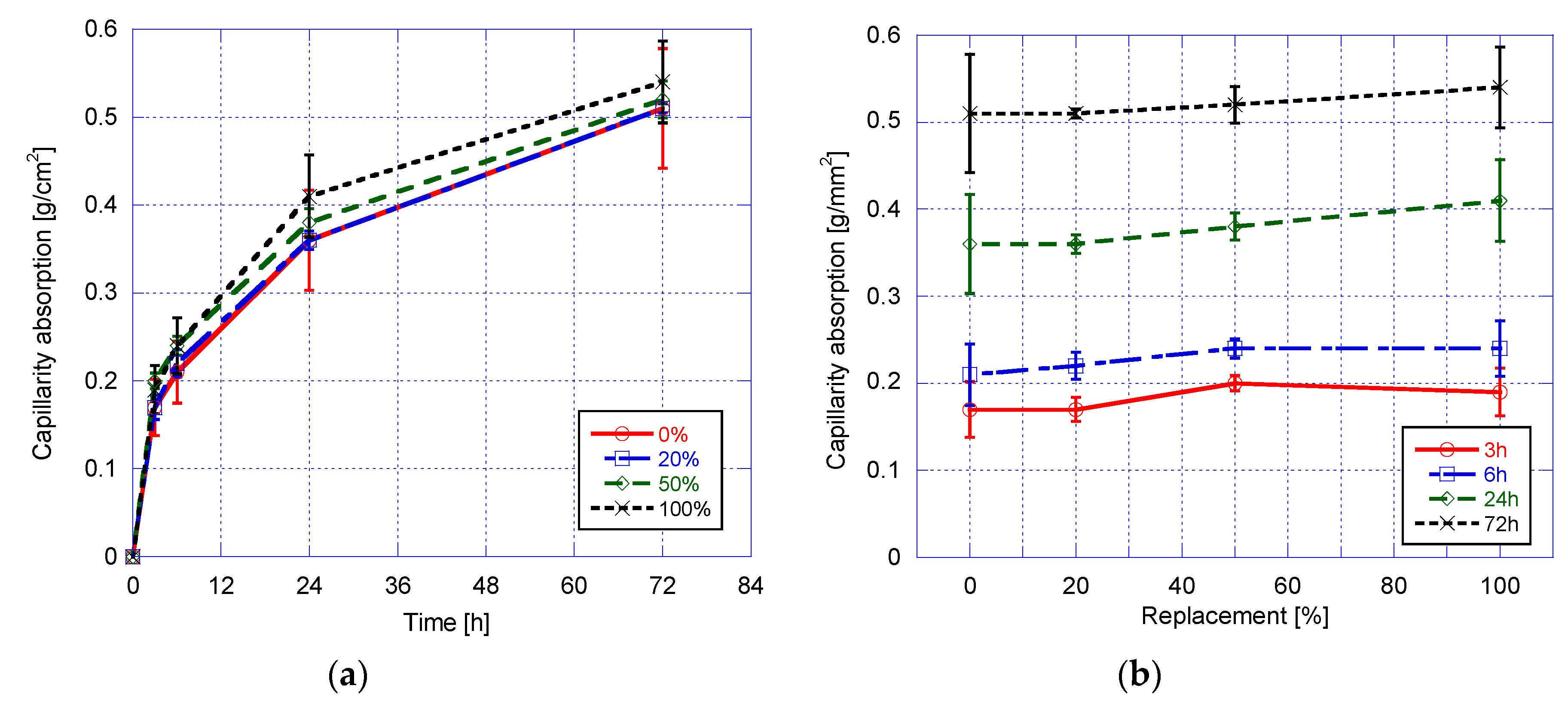
3.3. Durability
4. Conclusions
- The use of RCA with a water absorption twice that of NA requires compensation water, but the rounded shape of the RCA produced from concrete with EAFS (shape index 20% lower than NAC) makes it possible to use slightly lower effective w/c ratio to obtain the same workability;
- The replacement level affects the physical properties of RAC. Bulk density increased by 7%, unlike in current RAC (typically density decreases), due to the iron present in this recycled aggregate. Both porosity and capillarity slightly increase (18% and 9% for full replacement respectively) as replacement increases due to the porosity of the source concrete mortar;
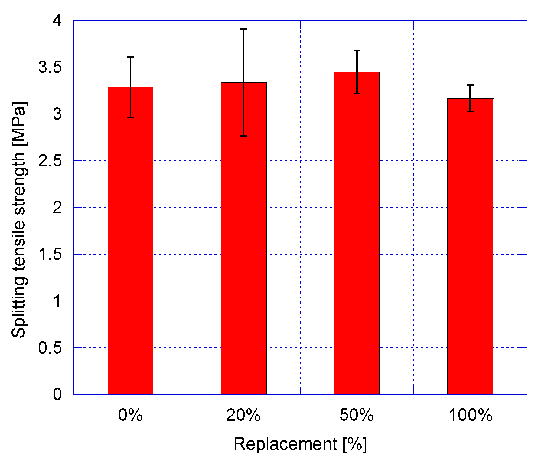
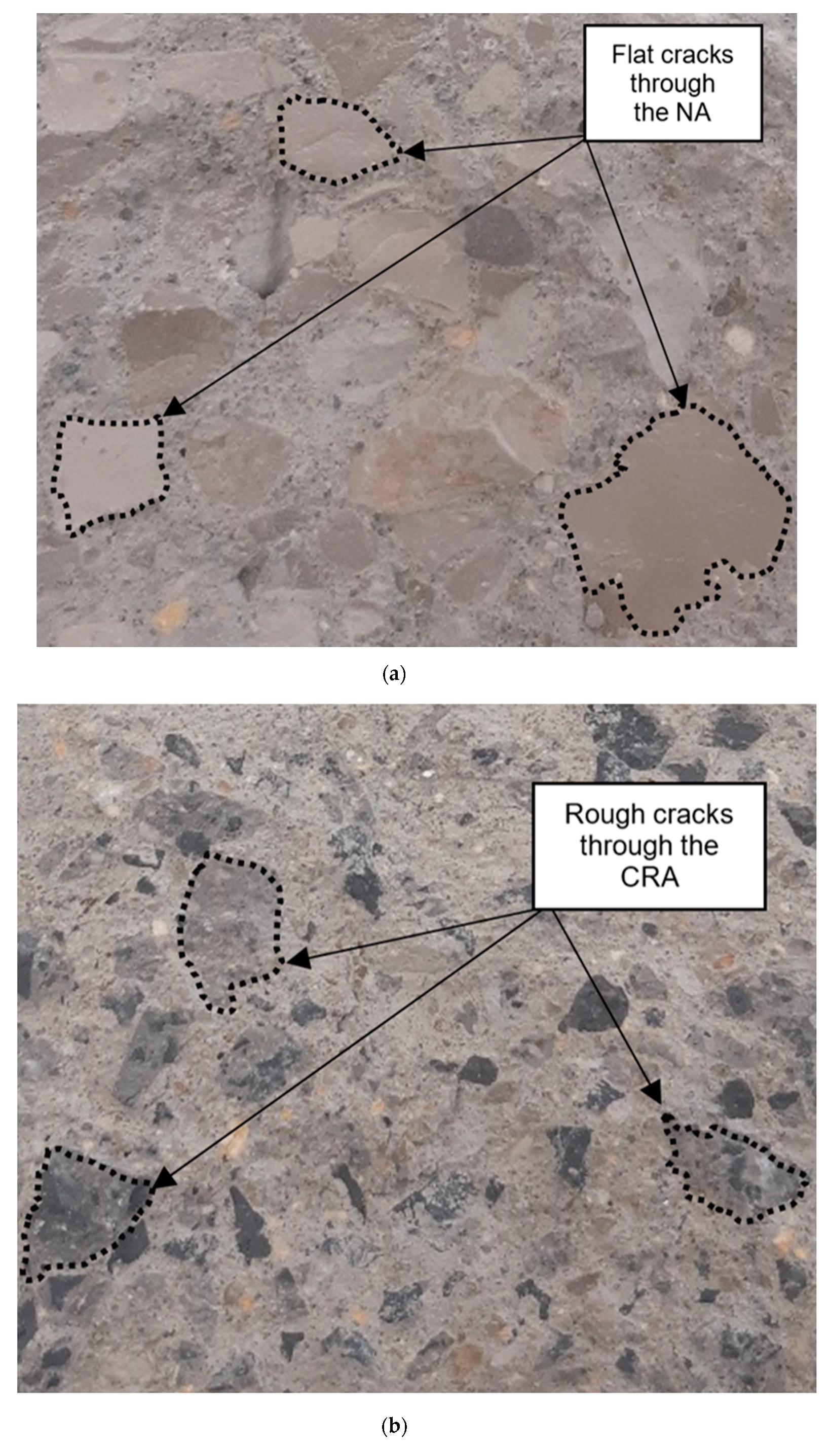
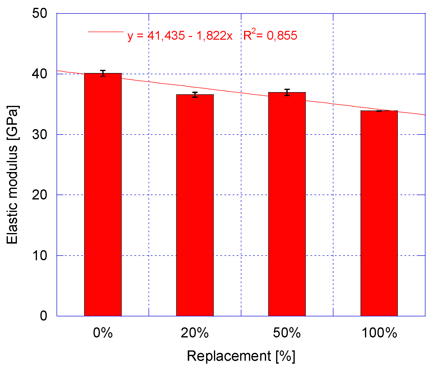
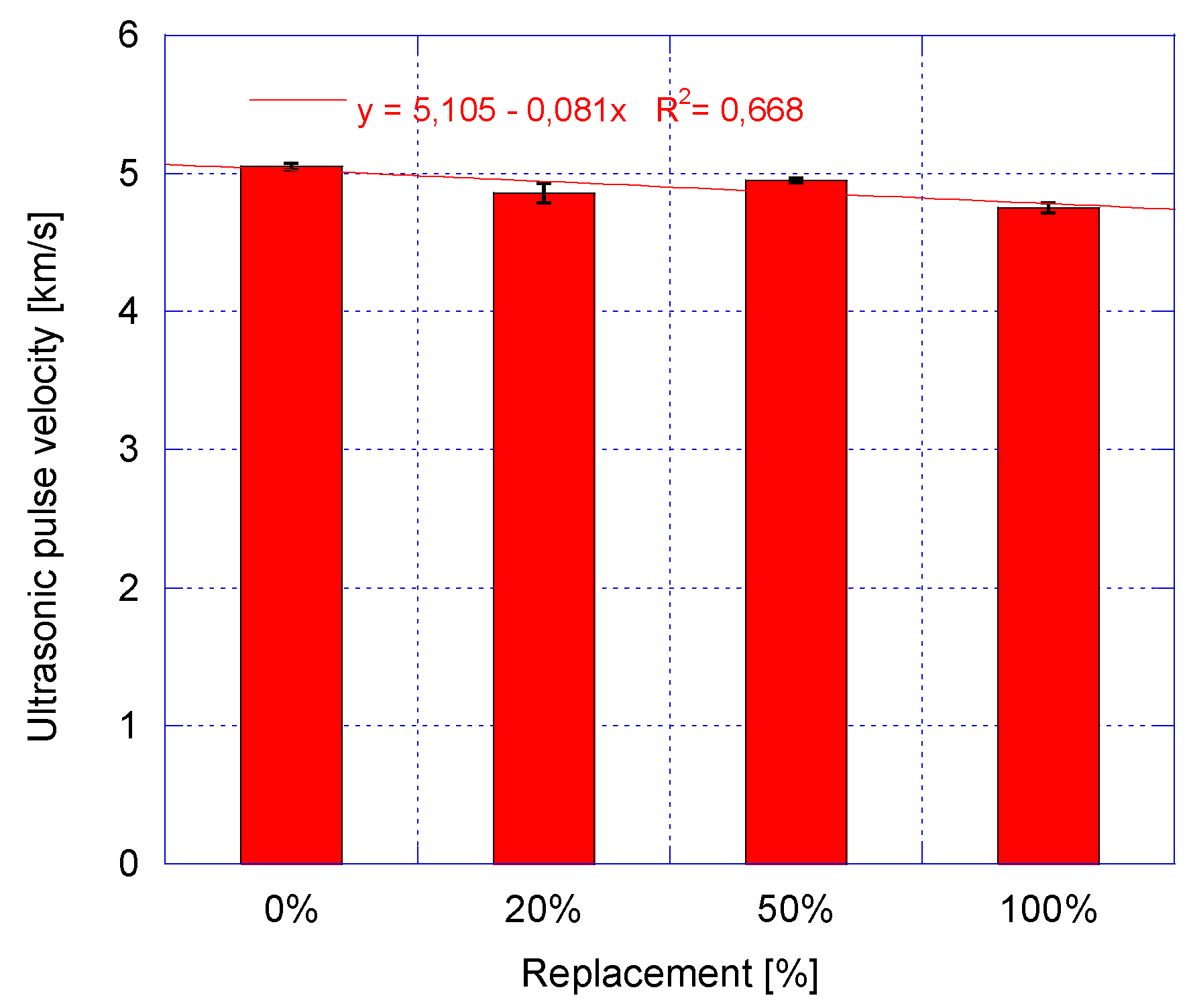
- Compressive strength is not affected by the replacement level for ages over 28 days due to the hydration of the unhydrated cement grains of the source concrete and to a good bond strength between RCA and the new mortar. This good bond, favoured by the cavernous form of EAFS in the source concrete, allows tensile strength to be very similar to that of NAC. On the other hand, the modulus of elasticity is the property most affected by the replacement of RCA, showing losses that can reach 17% with respect to NAC. Typical decreases of the modulus of elasticity caused by full recycled aggregate incorporation are higher than this value;
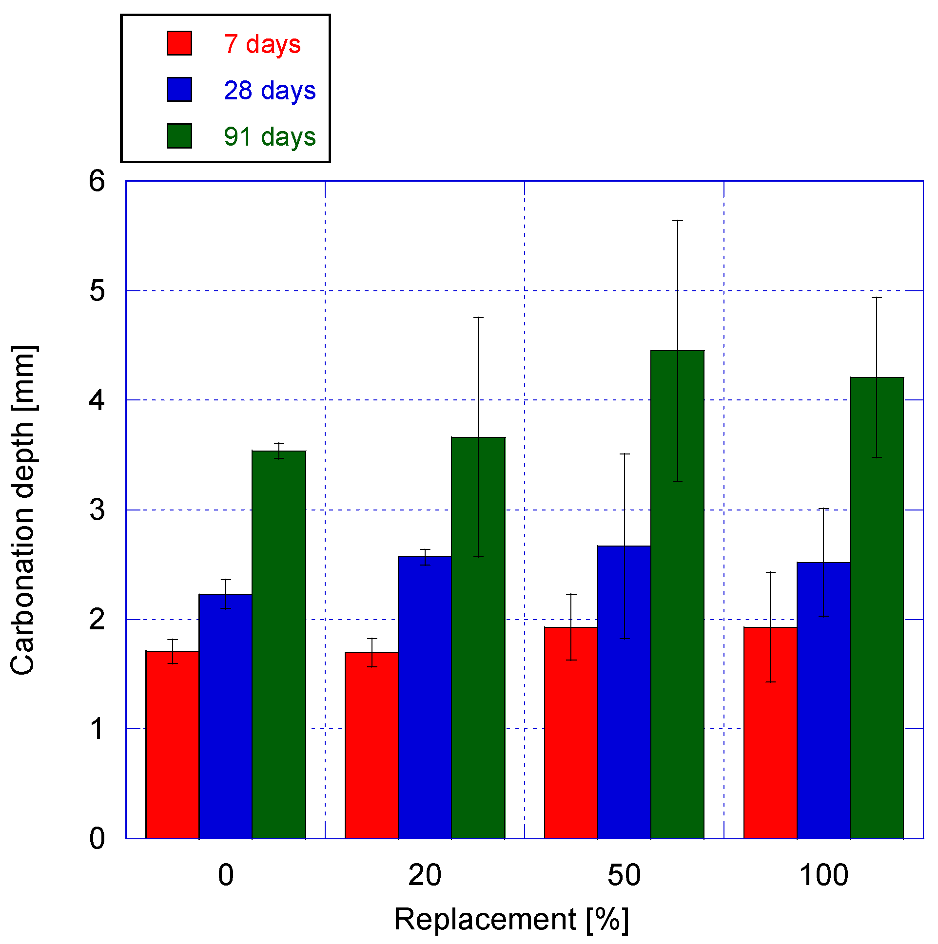
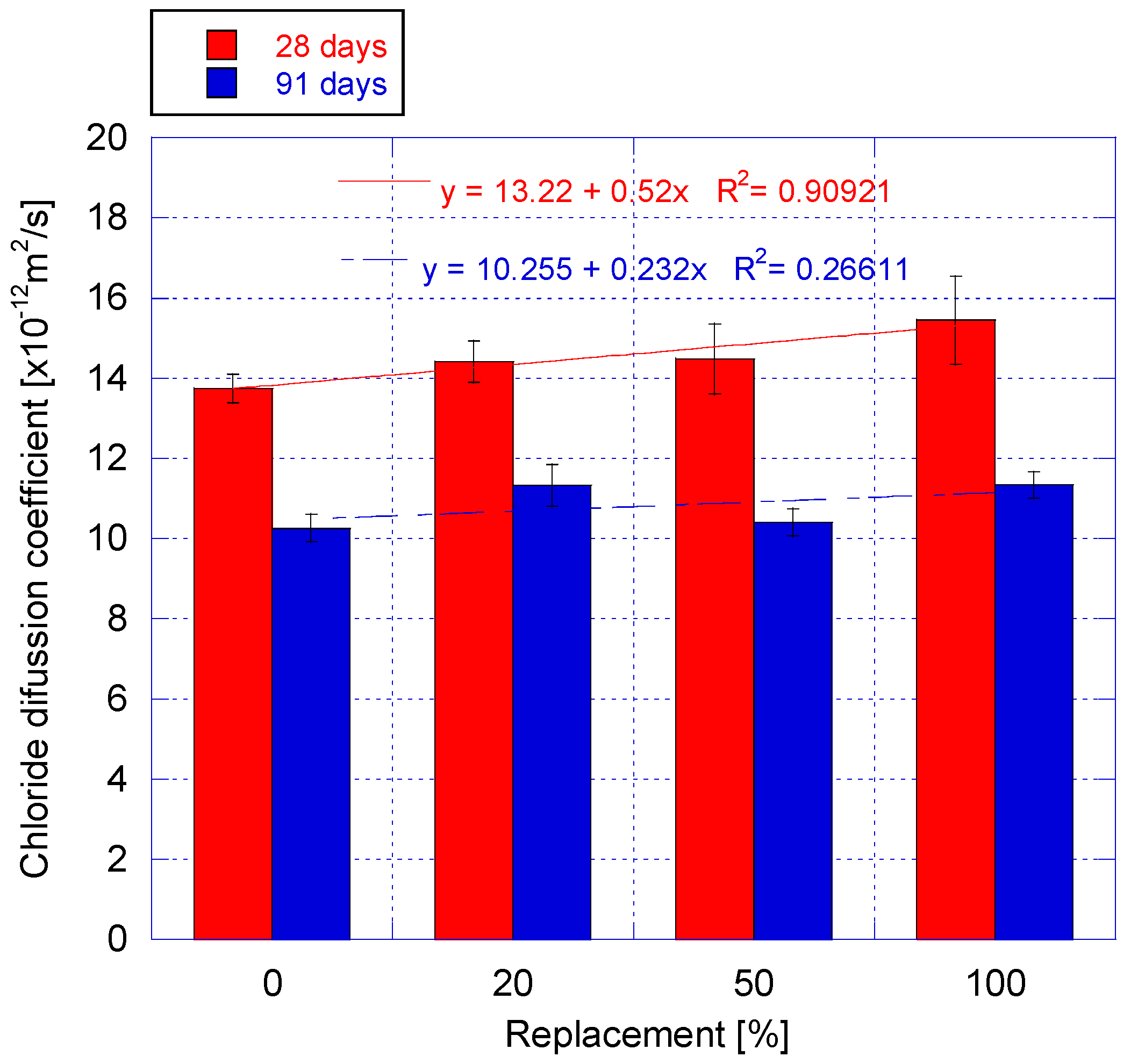
- Durability properties are negatively but slightly affected. Carbonation depths and chlorides diffusion coefficients are 15% and 25% higher respectively for full replacement at 91 days. Both properties are linked to the porosity of RAC and hence with the quality of the RCA used, which is reflected in a low w/c ratio and a good bond between aggregate and paste;
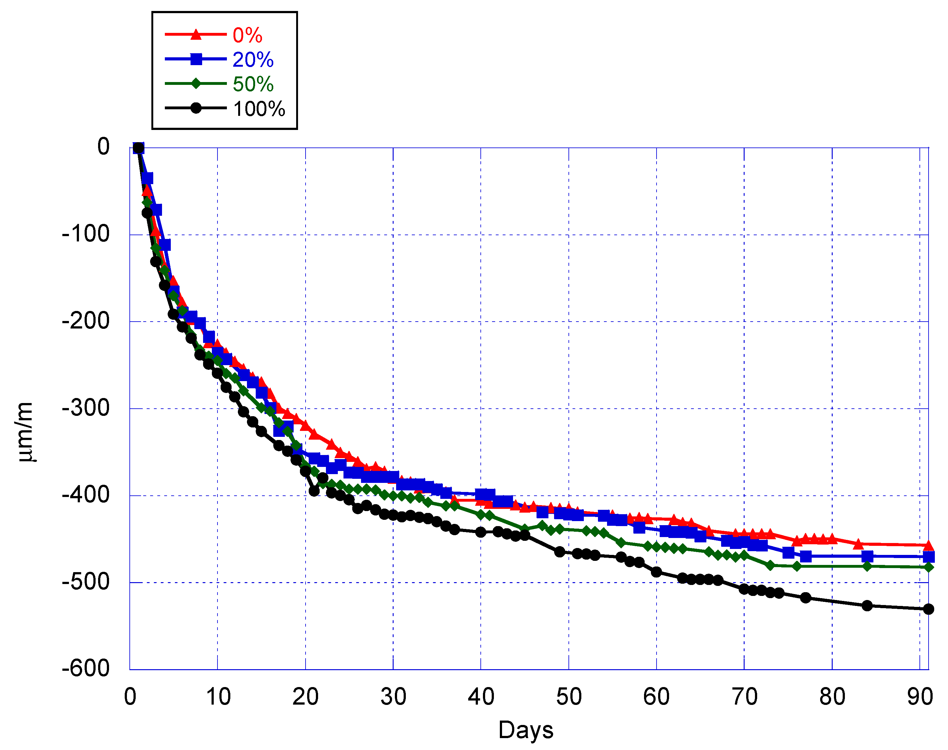
- Drying shrinkage values 13% higher for total replacements have been obtained at 91 days, consistent with the modulus of elasticity obtained;
- The mechanical and durability tests results obtained are satisfactory, usually near the lower limit of the interval of change found in the literature and sometimes showing a behaviour very similar to that of the reference NAC;
- Concrete designed by recycling an EAFS-based concrete has potential applications as a structural material and can also be used in applications where its self-weight is important, as in bridge counterweights, seawalls or radiation-proof structures.
Author Contributions
Funding
Acknowledgments
Conflicts of Interest
References
- Tam, V.W.; Soomro, M.; Evangelista, A.C.J. A review of recycled aggregate in concrete applications (2000–2017). Constr. Build. Mater. 2018, 172, 272–292. [Google Scholar] [CrossRef]
- Rao, A.; Jha, K.N.; Misra, S. Use of aggregates from recycled construction and demolition waste in concrete, Resour. Conserv. Recycl. 2007, 50, 71–81. [Google Scholar] [CrossRef]
- Faleschini, F.; De Marzi, P.; Pellegrino, C. Recycled concrete containing EAF slag: Environmental assessment through LCA. Eur. J. Environ. Civ. Eng. 2014, 18, 1009–1024. [Google Scholar] [CrossRef]
- Braymand, S.; Feraille, A.; Serres, N.; Feugeas, F. Benchmarking of materials composition and transportation influences on Life Cycle Assessment of Recycled Aggregate Concrete. In Proceedings of the 5th International Conference on Sustainable Solid Waste Management, Athens, Greece, 21–24 June 2017; pp. 1–3. [Google Scholar]
- McNeil, K.; Kang, T.H.-K. Recycled Concrete Aggregates: A Review. Int. J. Concr. Struct. Mater. 2013, 7, 61–69. [Google Scholar] [CrossRef]
- Shayan, A.; Xu, A. Performance and properties of structural concrete made with recycled concrete aggregate. Mater. J. 2003, 100, 371–380. [Google Scholar]
- Ministerio de Fomento de España. EHE-08: Instrucción de Hormigón Estructural. 2008. Available online: http://www.fomento.gob.es/MFOM/LANG_CASTELLANO/ORGANOS_COLEGIADOS/CPH/instrucciones/EHE08INGLES/ (accessed on 22 December 2019).
- UNE-EN 12620:2003+A1:2009. In Áridos Para Hormigón; Normalización Española: Madrid, Spain, 2009.
- Etxeberria, M.; Vázquez, E.; Marí, A.; Barra, M. Influence of amount of recycled coarse aggregates and production process on properties of recycled aggregate concrete. Cem. Concr. Res. 2007, 37, 735–742. [Google Scholar] [CrossRef]
- De Brito, J.; Ferreira, J.; Pacheco, J.; Soares, D.; Guerreiro, M. Structural, material, mechanical and durability properties and behaviour of recycled aggregates concrete. J. Build. Eng. 2016, 6, 1–16. [Google Scholar] [CrossRef]
- Silva, R.V.; De Brito, J.; Dhir, R.K. Establishing a relationship between modulus of elasticity and compressive strength of recycled aggregate concrete. J. Clean. Prod. 2016, 112, 2171–2186. [Google Scholar] [CrossRef]
- Marinkovic, S.; Radonjanin, V.; Malešev, M.; Ignjatović, I. Comparative environmental assessment of natural and recycled aggregate concrete. Waste Manag. 2010, 30, 2255–2264. [Google Scholar] [CrossRef]
- Anastasiou, E.; Filikas, K.G.; Stefanidou, M. Utilization of fine recycled aggregates in concrete with fly ash and steel slag. Constr. Build. Mater. 2014, 50, 154–161. [Google Scholar] [CrossRef]
- Silva, R.; De Brito, J.; Dhir, R. Properties and composition of recycled aggregates from construction and demolition waste suitable for concrete production. Constr. Build. Mater. 2014, 65, 201–217. [Google Scholar] [CrossRef]
- Thomas, C.; Setién, J.; Polanco, J.A.; Alaejos, P.; Sánchez De Juan, M. Durability of recycled aggregate concrete. Constr. Build. Mater. 2013, 40, 1054–1065. [Google Scholar] [CrossRef]
- Bravo, M.; De Brito, J.; Pontes, J.; Evangelista, L. Mechanical performance of concrete made with aggregates from construction and demolition waste recycling plants. J. Clean. Prod. 2015, 99, 59–74. [Google Scholar] [CrossRef]
- Topcu, I.B.; Sengel, S. Properties of concretes produced with waste concrete aggregate. Cem. Concr. Res. 2004, 34, 1307–1312. [Google Scholar] [CrossRef]
- Fiol, F.; Thomas, C.; Muñoz, C.; Ortega-López, V.; Manso, J.M. The influence of recycled aggregates from precast elements on the mechanical properties of structural self-compacting concrete. Constr. Build. Mater. 2018, 182, 309–323. [Google Scholar] [CrossRef]
- Matias, D.; de Brito, J.; Rosa, A.; Pedro, D. Durability of concrete with recycled coarse aggregates: Influence of superplasticizers. J. Mater. Civ. Eng. 2013, 26, 6014011. [Google Scholar] [CrossRef]
- Thomas, C.; Setién, J.; Polanco, J.; Cimentada, A.; Medina, C. Influence of curing conditions on recycled aggregate concrete. Constr. Build. Mater. 2018, 172, 618–625. [Google Scholar] [CrossRef]
- Thomas, C.; Cimentada, A.; Polanco, J.A.; Setién, J.; Méndez, D.; Rico, J. Influence of recycled aggregates containing sulphur on properties of recycled aggregate mortar and concrete, Compos. Part B Eng. 2013, 45, 474–485. [Google Scholar] [CrossRef]
- Gómez-Soberón, J.M.V. Porosity of recycled concrete with substitution of recycled concrete aggregate: An experimental study. Cem. Concr. Res. 2002, 32, 1301–1311. [Google Scholar] [CrossRef]
- de Brito, J.; Agrela, F. New Trends in Eco-Efficient and Recycled Concrete; Woodhead Publishing: Cambridge, UK, 2018. [Google Scholar]
- Bravo, M.; De Brito, J.; Pontes, J.; Evangelista, L. Durability performance of concrete with recycled aggregates from construction and demolition waste plants. Constr. Build. Mater. 2015, 77, 357–369. [Google Scholar] [CrossRef]
- Barra, M.; Vazquez, E. Properties of concretes with recycled aggregates: Influence of properties of the aggregates and their interpretation. In Sustainable Construction: Use of Recycled Concrete Aggregate: Proceedings of the International Symposium organised by the Concrete Technology Unit, University of Dundee and held at the Department of Trade and Industry Conference Centre, London, UK on 11–12 November 1998; Thomas Telford Publishing: London, UK, 2018; pp. 18–30. [Google Scholar]
- Ajdukiewicz, A.; Alina, K. Influence of recycled aggregates on mechanical properties of HS/HPC. Cem. Concr. Compos. 2002, 24, 269–279. [Google Scholar] [CrossRef]
- Tabsh, S.W.; Abdelfatah, A.S. Influence of recycled concrete aggregates on strength properties of concrete. Constr. Build. Mater. 2009, 23, 1163–1167. [Google Scholar] [CrossRef]
- Padmini, A.K.; Ramamurthy, K.; Mathews, M.S. Influence of parent concrete on the properties of recycled aggregate concrete. Constr. Build. Mater. 2009, 23, 829–836. [Google Scholar] [CrossRef]
- Arribas, I.; Vegas, I.; San-José, J.; Manso, J.M. Durability studies on steelmaking slag concretes. Mater. Des. 2014, 63, 168–176. [Google Scholar] [CrossRef]
- Poon, C.; Shui, Z.; Lam, L. Effect of microstructure of ITZ on compressive strength of concrete prepared with recycled aggregates. Constr. Build. Mater. 2004, 18, 461–468. [Google Scholar] [CrossRef]
- Li, W.; Xiao, J.; Sun, Z.; Kawashima, S.; Shah, S.P. Interfacial transition zones in recycled aggregate concrete with different mixing approaches. Constr. Build. Mater. 2012, 35, 1045–1055. [Google Scholar] [CrossRef]
- Rahal, K. Mechanical properties of concrete with recycled coarse aggregate. Build. Environ. 2007, 42, 407–415. [Google Scholar] [CrossRef]
- Alexandridou, C.; Angelopoulos, G.N.; Coutelieris, F.A. Mechanical and durability performance of concrete produced with recycled aggregates from Greek construction and demolition waste plants. J. Clean. Prod. 2018, 176, 745–757. [Google Scholar] [CrossRef]
- Pacheco, J.; De Brito, J.; Chastre, C.; Evangelista, L. Experimental investigation on the variability of the main mechanical properties of concrete produced with coarse recycled concrete aggregates. Constr. Build. Mater. 2019, 201, 110–120. [Google Scholar] [CrossRef]
- Xiao, J.; Li, J.; Zhang, C. Mechanical properties of recycled aggregate concrete under uniaxial loading. Cem. Concr. Res. 2005, 35, 1187–1194. [Google Scholar] [CrossRef]
- Kwan, W.H.; Ramli, M.; Kam, K.J.; Sulieman, M.Z. Influence of the amount of recycled coarse aggregate in concrete design and durability properties. Constr. Build. Mater. 2012, 26, 565–573. [Google Scholar] [CrossRef]
- Xiao, J.; Li, W.; Poon, C. Recent studies on mechanical properties of recycled aggregate concrete in China—A review. Sci. China Technol. Sci. 2012, 55, 1463–1480. [Google Scholar] [CrossRef]
- Pacheco, J.; De Brito, J.; Chastre, C.; Evangelista, L. Scatter of Constitutive Models of the Mechanical Properties of Concrete: Comparison of Major International Codes. J. Adv. Concr. Technol. 2019, 17, 102–125. [Google Scholar] [CrossRef]
- Corinaldesi, V. Mechanical and elastic behaviour of concretes made of recycled-concrete coarse aggregates. Constr. Build. Mater. 2010, 24, 1616–1620. [Google Scholar] [CrossRef]
- Thomas, C.; Carrascal, I.; Setién, J.; Polanco, J.A. Determinación del límite a fatiga en hormigones reciclados de aplicación estructural—Determining the fatigue limit recycled concrete structural application. An. Mecánica La Fract. 2009, 1, 283–289. (In Spanish) [Google Scholar]
- Thomas, C.; Setién, J.; Polanco, J.A.; Lombillo, I.; Cimentada, A.I. Fatigue limit of recycled aggregate concrete. Constr. Build. Mater. 2014, 52, 146–154. [Google Scholar] [CrossRef]
- Thomas, C.; De Brito, J.; Gil, V.; Sainz-Aja, J.; Cimentada, A. Multiple recycled aggregate properties analysed by X-ray microtomography. Constr. Build. Mater. 2018, 166, 171–180. [Google Scholar] [CrossRef]
- Li, X. Recycling and reuse of waste concrete in China: Part I. Material behaviour of recycled aggregate concrete. Resour. Conserv. Recycl. 2008, 53, 36–44. [Google Scholar] [CrossRef]
- Kou, S.; Poon, C. Properties of self-compacting concrete prepared with recycled glass aggregate. Cem. Concr. Compos. 2009, 31, 107–113. [Google Scholar] [CrossRef]
- Silva, R.V.; Neves, R.; De Brito, J.; Dhir, R.K. Carbonation behaviour of recycled aggregate concrete. Cem. Concr. Compos. 2015, 62, 22–32. [Google Scholar] [CrossRef]
- de Juan, M.S.; Gutiérrez, P.A. Study on the influence of attached mortar content on the properties of recycled concrete aggregate. Constr. Build. Mater. 2009, 23, 872–877. [Google Scholar] [CrossRef]
- Wang, L.; Wang, J.; Qian, X.; Chen, P.; Xu, Y.; Guo, J. An environmentally friendly method to improve the quality of recycled concrete aggregates. Constr. Build. Mater. 2017, 144, 432–441. [Google Scholar] [CrossRef]
- Shima, H.; Tateyashiki, H.; Matsuhashi, R.; Yoshida, Y. An Advanced Concrete Recycling Technology and its Applicability Assessment through Input-Output Analysis. J. Adv. Concr. Technol. 2005, 3, 53–67. [Google Scholar] [CrossRef]
- Pawluczuk, E.; Kalinowska-Wichrowska, K.; Bołtryk, M.; Jiménez, J.R.; Fernández, J.M. The Influence of Heat and Mechanical Treatment of Concrete Rubble on the Properties of Recycled Aggregate Concrete. Materials 2019, 12, 367. [Google Scholar] [CrossRef] [PubMed]
- Braymand, S.; Roux, S.; Fares, H.; Déodonne, K.; Feugeas, F. Separation and quantification of attached mortar in recycled concrete aggregates. Waste Biomass Valorization 2017, 8, 1393–1407. [Google Scholar] [CrossRef]
- Lotfi, S.; Eggimann, M.; Wagner, E.; Mróz, R.; Deja, J. Performance of recycled aggregate concrete based on a new concrete recycling technology. Constr. Build. Mater. 2015, 95, 243–256. [Google Scholar] [CrossRef]
- Khatib, J.M. Properties of concrete incorporating fine recycled aggregate. Cem. Concr. Res. 2005, 35, 763–769. [Google Scholar] [CrossRef]
- Papayianni, I.; Anastasiou, E. Utilization of electric arc furnace steel slags in concrete products. In 6th European Slag Conference: Proceedings Ferrous Slag-Resource Development for an Environmentally Sustainable World; EUROSLAG Publication: Madrid, Spain, 2010; pp. 319–334. [Google Scholar]
- Monosi, S.; Ruello, M.L.; Sani, D. Electric arc furnace slag as natural aggregate replacement in concrete production. Cem. Concr. Compos. 2016, 66, 66–72. [Google Scholar] [CrossRef]
- Abu-Eishah, S.I.; El-Dieb, A.S.; Bedir, M.S. Performance of concrete mixtures made with electric arc furnace (EAF) steel slag aggregate produced in the Arabian Gulf region. Constr. Build. Mater. 2012, 34, 249–256. [Google Scholar] [CrossRef]
- Faleschini, F.; Fernández-Ruíz, M.A.; Zanini, M.A.; Brunelli, K.; Pellegrino, C.; Hernández-Montes, E. High performance concrete with electric arc furnace slag as aggregate: Mechanical and durability properties. Constr. Build. Mater. 2015, 101, 113–121. [Google Scholar] [CrossRef]
- Fonseca, N.; De Brito, J.; Evangelista, L. The influence of curing conditions on the mechanical performance of concrete made with recycled concrete waste. Cem. Concr. Compos. 2011, 33, 637–643. [Google Scholar] [CrossRef]
- Rodrigues, F.; Evangelista, L.; De Brito, J. A new method to determine the density and water absorption of fine recycled aggregates. Mater. Res. 2013, 16, 1045–1051. [Google Scholar] [CrossRef]
- Mehta, P.K.; Monteiro, P.J.M. Concrete microstructure, Properties and Materials. 2017. Available online: http://matteopro.com/images/materiali-non-convenzionali/Concrete_microstrutture_-_book.pdf (accessed on 22 December 2019).
- Silva, R.V.; De Brito, J.; Dhir, R.K. Tensile strength behaviour of recycled aggregate concrete. Constr. Build. Mater. 2015, 83, 108–118. [Google Scholar] [CrossRef]
- Kou, S.-C.; Poon, C.-S.; Wan, H.-W. Properties of concrete prepared with low-grade recycled aggregates. Constr. Build. Mater. 2012, 36, 881–889. [Google Scholar] [CrossRef]
- Ryu, J.S. An experimental study on the effect of recycled aggregate on concrete properties. Mag. Concr. Res. 2002, 54, 7–12. [Google Scholar] [CrossRef]
- Suryavanshi, A.K.; Narayan Swamy, R. Stability of Friedel’s salt in carbonated concrete structural elements. Cem. Concr. Res. 1996, 26, 729–741. [Google Scholar] [CrossRef]
- Maekawa, K.; Ishida, T.; Kishi, T. Multi-scale Modeling of Concrete Performance. J. Adv. Concr. Technol. 2003, 1, 91–126. [Google Scholar] [CrossRef]
- Fédération Internationale du Bétom. Code-Type Models for Structural Behaviour of Concrete; Fédération Internationale du Béton: Bulletin, Lausanne, Switzerland, 2013. [Google Scholar]


| Acronym | Meaning |
|---|---|
| RA | Recycled aggregate |
| CRA | Coarse recycled aggregate |
| RCA | Recycled concrete aggregate |
| RAC | Recycled aggregate concrete |
| NA | Natural aggregate |
| NAC | Natural aggregate concrete |
| CDW | Construction and demolition waste |
| EAFS | Electric arc furnace slags |
| Material | Bulk Density [g/cm3] | Apparent Bulk Density [g/cm3] | Water Absorption [%wt.] | Shape Index [%] | Los Angeles Wear [%] |
|---|---|---|---|---|---|
| 12/20 | 2.66 | 1.36 | 1.3 | 14.5 | 26 |
| 6/12 | 2.66 | 1.38 | 1.5 | 19.7 | 28 |
| 2/6 | 2.66 | 1.41 | 1.0 | 16.4 | - |
| 0/4 | 2.67 | 1.54 | 0.3 | - | - |
| 0/2 | 2.67 | 1.57 | 0.2 | - | - |
| CRA 4/20 | 2.96 | 1.52 | 3.5 | 13.4 | 26.9 |
| Material/Property | Mix Proportions [kg/m3] | |||
|---|---|---|---|---|
| CRA replacement | 0% | 20% | 50% | 100% |
| CEM I 42.5 R | 350 | 350 | 350 | 350 |
| Effective water | 175 | 174.3 | 173.3 | 171.5 |
| Compensation water | 18.0 | 29.1 | 34.6 | 43.9 |
| NA gravel (12/20) | 434.4 | 347.5 | 217.19 | - |
| NA gravel (6/12) | 566.6 | 453.26 | 283.29 | - |
| NA gravel (2/6) | 207.8 | 173.67 | 122.1 | 36.2 |
| NA sand (0/4) | 417.1 | 417.1 | 417.1 | 417.1 |
| NA sand (0/2) | 265.4 | 265.4 | 265.4 | 265.4 |
| CRA > 22.4 mm | - | 1.5 | 3.9 | 7.7 |
| CRA 16–22.4 mm | - | 35.6 | 88.9 | 177.9 |
| CRA 11.2–16 mm | - | 76.7 | 191.8 | 383.6 |
| CRA 8–11.2 mm | - | 56.8 | 142,0 | 283.9 |
| CRA 5.6–8 mm | - | 49.8 | 124.6 | 249.2 |
| CRA 4–5.6 mm | - | 39.5 | 98.7 | 197.4 |
| Effective w/c ratio | 0.500 | 0.498 | 0.495 | 0.490 |
| Slump [mm] | 70 | 65 | 68 | 72 |
| Fresh state density [kg/m3] | 2424 | 2470 | 2563 | 2603 |
| Replacement | Bulk Density [g/cm3] | Apparent Density [g/cm3] | SSD Density [g/cm3] | Fresh State Density [g/cm3] | Open Porosity [% vol.] | Water Absorption [% wt.] |
|---|---|---|---|---|---|---|
| 0% | 2.280 ± 0.01 | 2.620 ± 0.008 | 2.410 ± 0.01 | 2.42 | 12.70 ± 0.28 | 5.56 ± 0.14 |
| 20% | 2.300 ± 0.008 | 2.680 ± 0.018 | 2.440 ± 0.01 | 2.47 | 14.31 ± 0.31 | 6.23 ± 0.12 |
| 50% | 2.390 ± 0.009 | 2.740 ± 0.01 | 2.520 ± 0.015 | 2.56 | 12.73 ± 0.41 | 5.33 ± 0.21 |
| 100% | 2.460 ± 0.005 | 2.920 ± 0.018 | 2.620 ± 0.005 | 2.60 | 15.62 ± 0.53 | 6.34 ± 0.22 |
© 2019 by the authors. Licensee MDPI, Basel, Switzerland. This article is an open access article distributed under the terms and conditions of the Creative Commons Attribution (CC BY) license (http://creativecommons.org/licenses/by/4.0/).
Share and Cite
Tamayo, P.; Pacheco, J.; Thomas, C.; de Brito, J.; Rico, J. Mechanical and Durability Properties of Concrete with Coarse Recycled Aggregate Produced with Electric Arc Furnace Slag Concrete. Appl. Sci. 2020, 10, 216. https://doi.org/10.3390/app10010216
Tamayo P, Pacheco J, Thomas C, de Brito J, Rico J. Mechanical and Durability Properties of Concrete with Coarse Recycled Aggregate Produced with Electric Arc Furnace Slag Concrete. Applied Sciences. 2020; 10(1):216. https://doi.org/10.3390/app10010216
Chicago/Turabian StyleTamayo, Pablo, Joao Pacheco, Carlos Thomas, Jorge de Brito, and Jokin Rico. 2020. "Mechanical and Durability Properties of Concrete with Coarse Recycled Aggregate Produced with Electric Arc Furnace Slag Concrete" Applied Sciences 10, no. 1: 216. https://doi.org/10.3390/app10010216
APA StyleTamayo, P., Pacheco, J., Thomas, C., de Brito, J., & Rico, J. (2020). Mechanical and Durability Properties of Concrete with Coarse Recycled Aggregate Produced with Electric Arc Furnace Slag Concrete. Applied Sciences, 10(1), 216. https://doi.org/10.3390/app10010216