Joule Heating Effects in Electrokinetic Remediation: Role of Non-Uniform Soil Environments: Temperature Profile Behavior and Hydrodynamics
Abstract
1. Introduction
2. Problem Formulation of the Heat Transfer Model
3. Formulation of the Hydrodynamic Model
- (1)
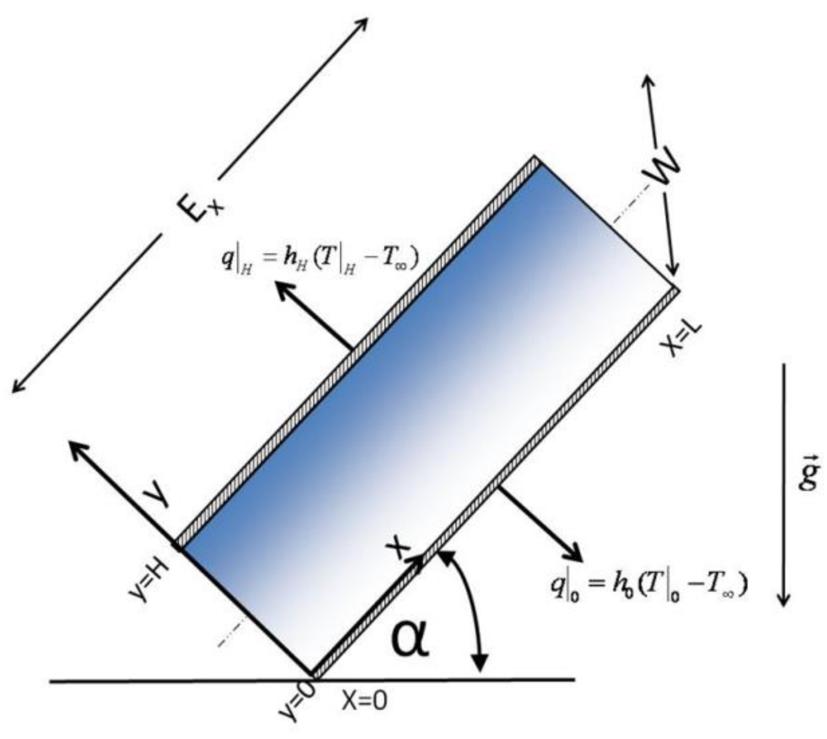
- Identifying Geometry: The geometry used in this study is of rectangular shape with dimensions L, H, W (Figure 1).
- (2)
- Selection of the Coordinate System: The coordinate system is “anchored” in one of the vertices of the capillary domain to simplify the calculation of the flow rate (or flow) (Figure 1).
- (3)
- Kinematics of Flow: Components of the velocity profile are described. Therefore, for the case under analysis:
- a.
- (the flow of the fluid is in the axial direction only since ends effects are neglected)
- b.
- (there is no net flow perpendicular to the axial flow in the domain)
- c.
- (there is no net flow in the direction perpendicular to the xy plane of the domain)Based on the description above, we can postulate that the hydrodynamics is given by(vz, 0, 0) as the unidimensional vector.
- (4)
- Boussinesq Approximation: This approximation uses the incompressibility condition everywhere except in the buoyancy term [24]. By using this approximation, all the effects of temperature on the system and due to Joule heating are considered only in the density variation with the temperature. Other properties such as viscosity and the heat capacity are considered constant in the model equations. Basically, the fluid behaves as incompressible, i.e., as it is assumed that there is no density variation in the case of conservation of total mass and, therefore, the continuity equation with the divergence of the vector field equated to zero is valid. This condition leads to the following conclusion:because (additionally) it assumed symmetry in the coordinate “z”.
- (5)
- Application of the Conservation of Momentum: Since the buffer is assumed to exhibit Newtonian fluid behavior, the Navier-Stokes equation is valid [21]. In the axial flow direction and with the assumption indicate above, the Navier-Stokes equation for the x-component is:
4. Solution and Obtaining Both the Heat Transfer and Velocity Profile Equations
4.1. Solution to Differential Model: The Distinct Heat Transfer Regimes
4.2. Solution and Obtaining the Velocity Profile Equation
- Case 1: Symmetrical case, (R = 1) i.e., both Nu values at the different walls are the same
- Case 2: Adiabatic case, (R = 0) at the wall positioned at . No heat flux is present at this location.
- Case 3: Well-mixed case, (R → ∞) at the wall positioned at . This case has an excellent heat transfer at the position.
5. Different Heat Transfer and Hydrodynamic Regimes: Analysis, Numerical Illustration, and Discussion
5.1. Case 1: Symmetrical Case
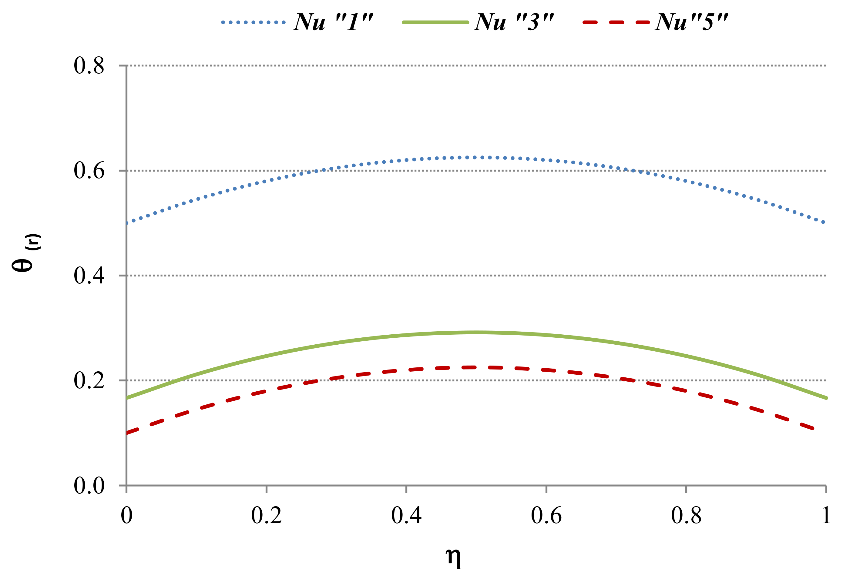
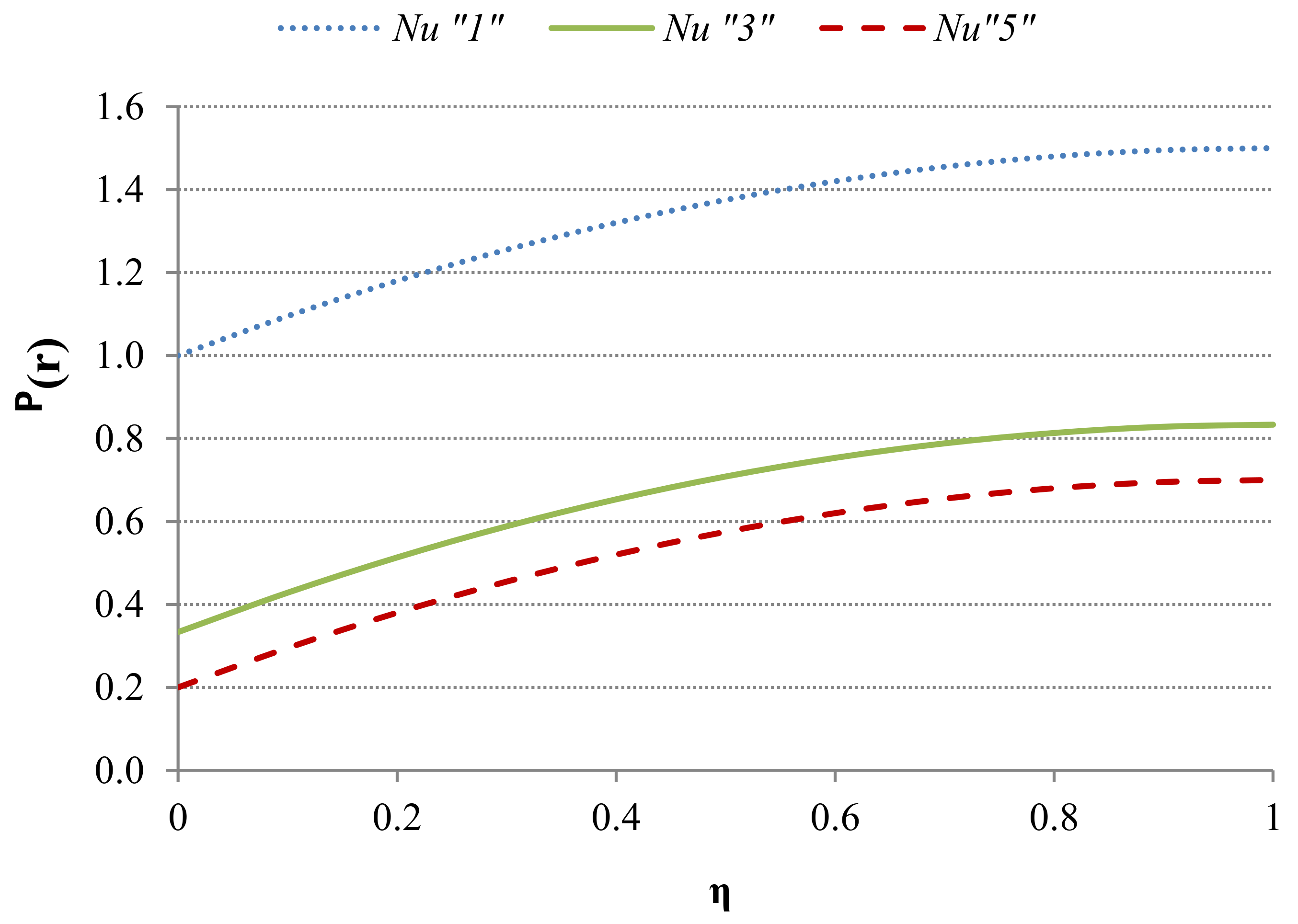
5.1.1. Case 1: Applied to the Heat Transfer Regime
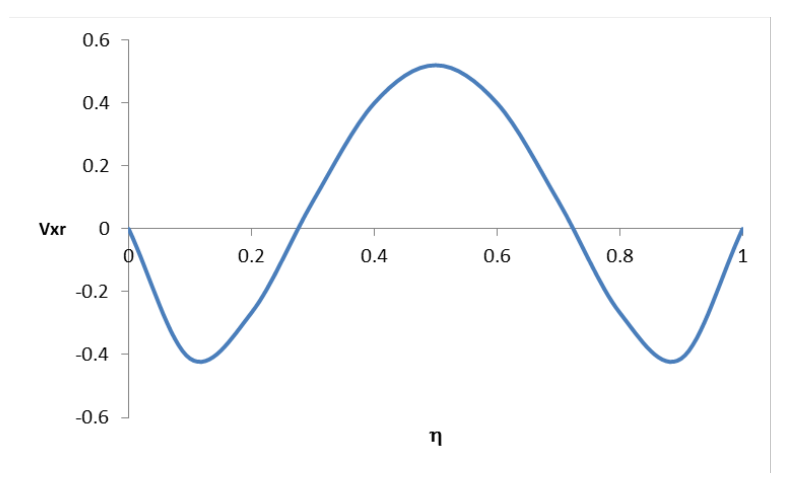
5.1.2. Case 1: Applied to the Hydrodynamic Regime
5.2. Case 2: Adiabatic Case for the Capillary Wall Located at
5.2.1. Case 2: Applied to the Heat Transfer Regime
5.2.2. Case 2: Applied to the Hydrodynamic Regime
5.3. Case 3: Well Mixed Case at the Wall Located at
5.3.1. Case 3: Applied to the Heat Transfer Regime
5.3.2. Case 3: Applied to the Hydrodynamic Regime
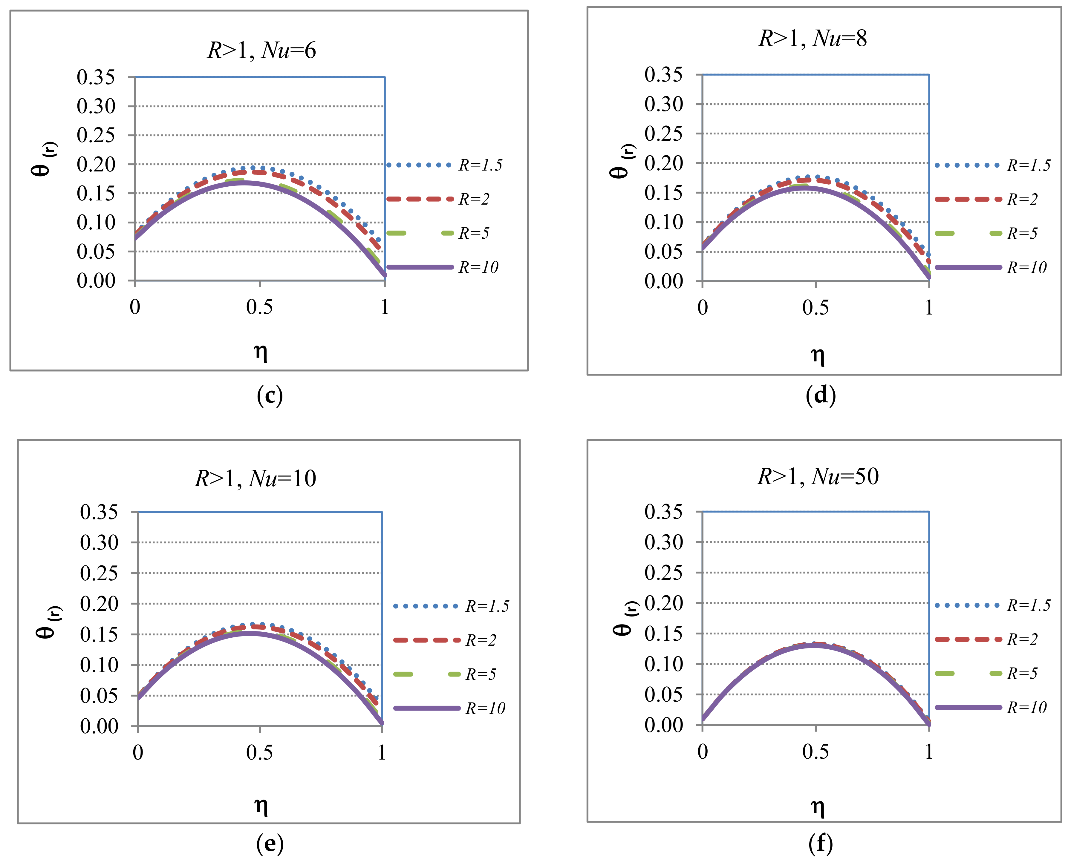
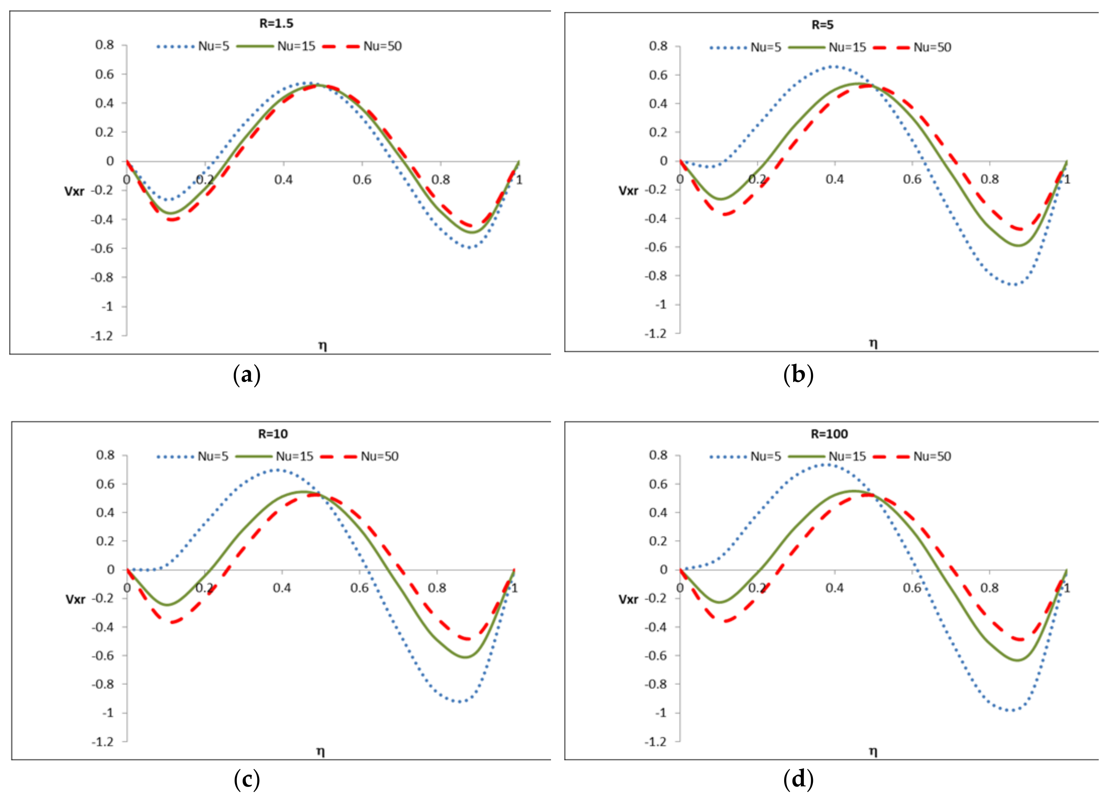
5.4. Case 4: Favorable Heat Transfer at the Wall Located at When R > 1
5.4.1. Case 4: Applied to the Heat Transfer Regime
5.4.2. Case 4: Applied to the Hydrodynamic Regime
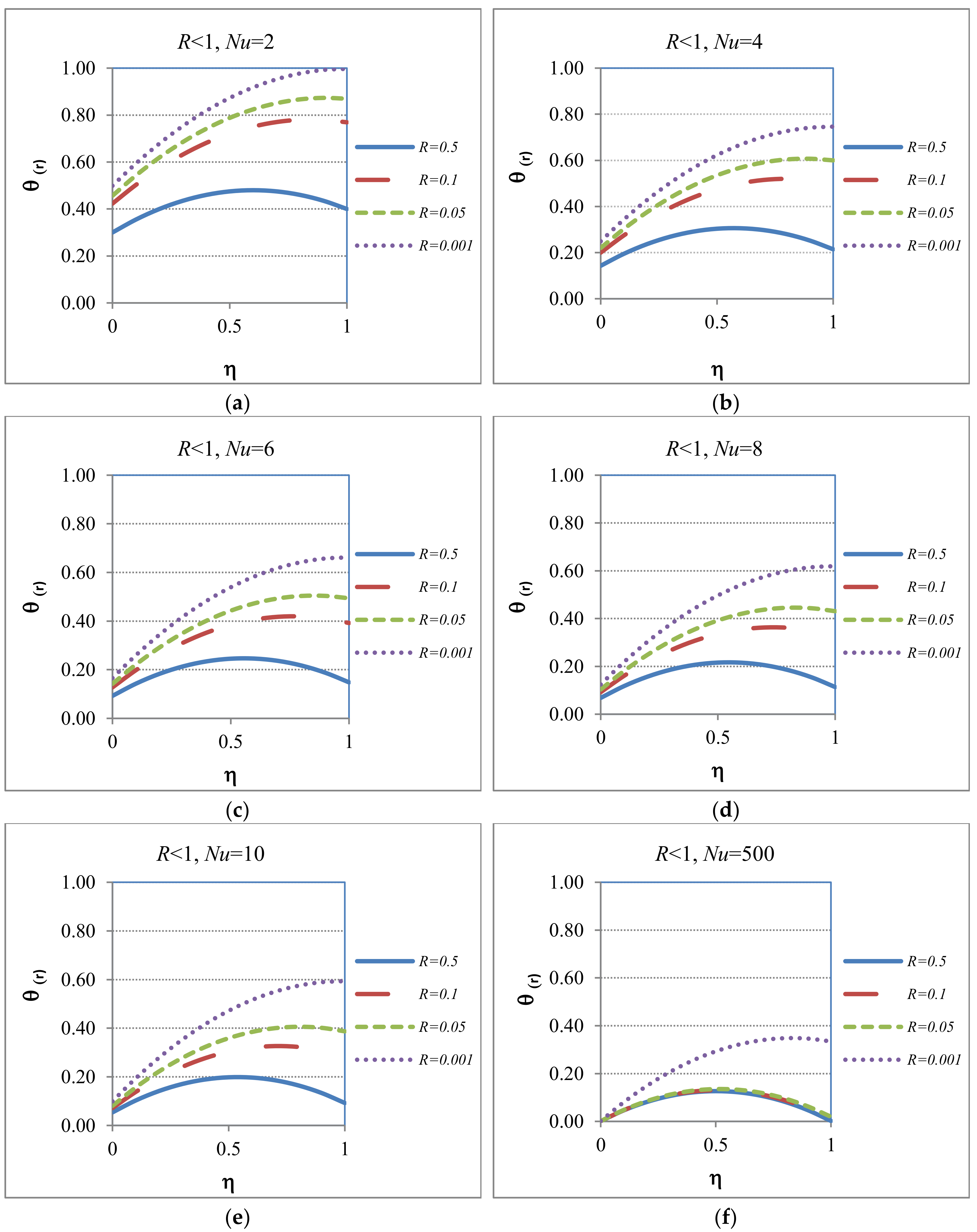
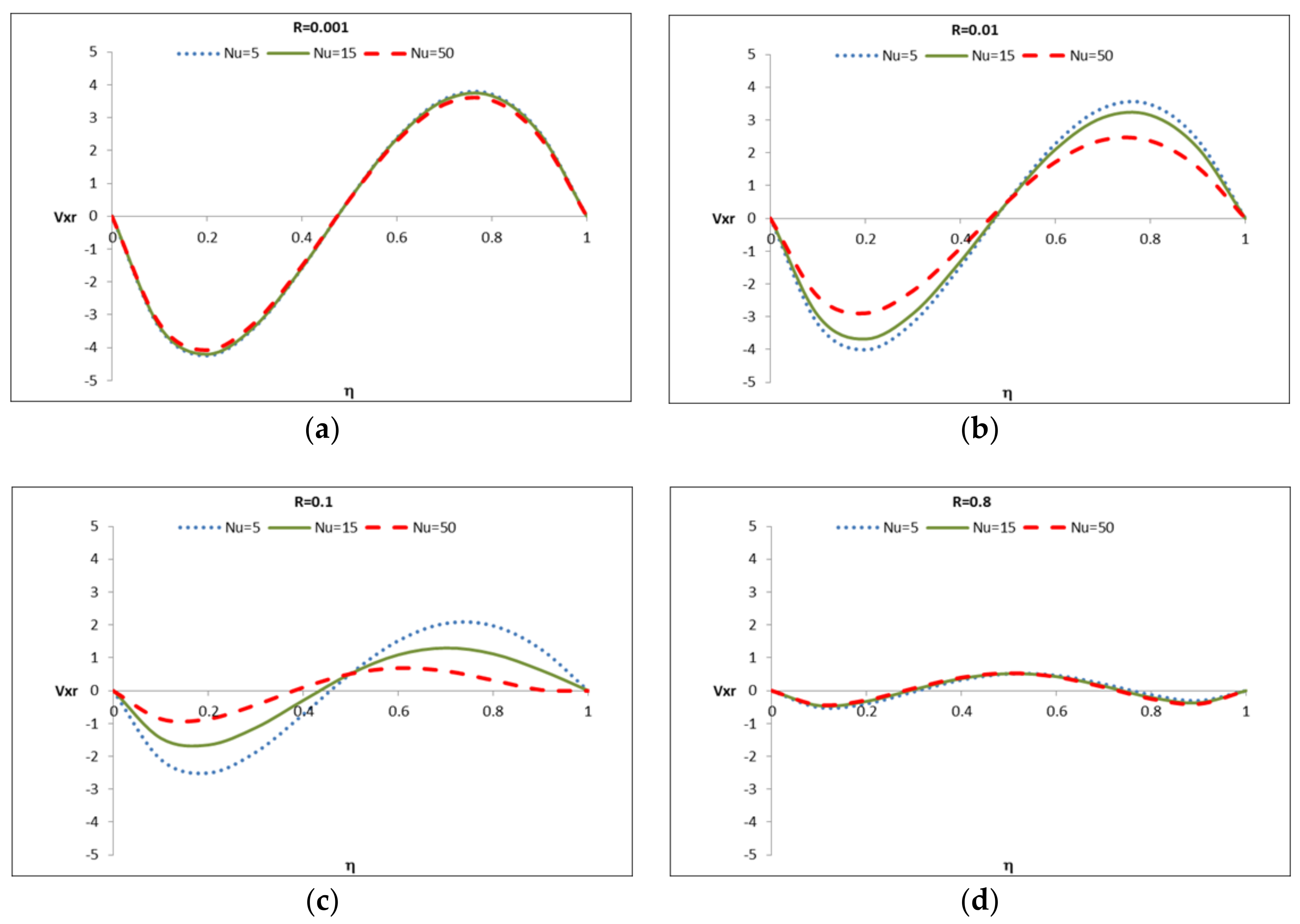
5.5. Case 5: Unfavorable Heat Transfer at the Wall Located at , (R < 1)
5.5.1. Case 5: Applied to the Heat Transfer Regime
5.5.2. Case 5: Applied to the Hydrodynamic Regime
6. Average (Mean) Temperature Analysis of the Capillary
- (a)
- Symmetrical Case: R = 1, F(R = 1, Nu) = 1, gives:
- (b)
- Adiabatic Case for the Wall located at . For this case , and it leads to:
- (c)
- Well-Mixed Case for the Wall Located at . For this case (), we have, , and it leads to:Regarding the general case, R < 1 and R > 1, these can be obtained directly from Equation (68).
7. Conclusions
Author Contributions
Funding
Acknowledgments
Conflicts of Interest
Nomenclature
| A,B,C | Parameters |
| C1,C2 | Integration constants |
| D1,D2 | Integration constants |
| Ex | Electric field in the axial direction (Vm−1) |
| F | Function of the ratio between the Nusselt numbers at both walls of the capillary and Nusselt = |
| G | Gravity (m s−2) |
| Gr | Grashof number |
| H | Heat transfer coefficient (Wm−2 K−1) |
| H | Capillary height (m) |
| I | Current (A) |
| Integrals of currents | |
| K | Thermal conductivity (Wm−1K−1) |
| L | Capillary length (m) |
| Nu | Nusselt number = [hL/k] |
| Q | Electric charge (C) |
| Q | Heat generation due to Joule heating |
| R | Electrical resistance (Ω) |
| R | Ratio between the Nusselt numbers at both walls of the capillary = [Nu1/Nu0] |
| T | Time (s) |
| T | Temperature (K) |
| T∞ | Temperature outside of the capillary domain (K) |
| Vx | Dimensionless velocity |
| W | Capillary depth (m) |
| Dimensionless capillary length | |
| x,y,z | Coordinates (m) |
Greek Symbols
| α | Inclination angle of capillary with respect to the orientation of gravity |
| η | Dimensionless capillary height |
| ρ | Fluid density (kg m−3) |
| Average density | |
| β | Volumetric thermal expansion coefficient |
| Dimensionless temperature = [(T − T∞)/T∞] | |
| Dimensionless reduced temperature | |
| Average dimensionless temperature | |
| Φ | Dimensionless Joule heating generation = [QH2/k T∞] |
Sub-Indexes
| 0 | Indicates any dimensional and/or non-dimensional variable located at the capillary wall y = 0 |
| H | Indicates any variable located at the capillary wall y = H |
| 1 | Indicates any dimensionless variable located at the capillary wall |
| S | Symmetrical |
| A | Adiabatic |
| WM | Well-mixed |
| r | Reduced |
References
- Reddy, K.R.; Cameselle, C. Electrochemical Remediation Technologies for Polluted Soils, Sediments and Groundwater; John Wiley & Sons: New York, NY, USA, 2009. [Google Scholar]
- Iyer, R. Electrokinetic Remediation. Particul. Sci. Technol. 2001, 19, 219–228. [Google Scholar] [CrossRef]
- Wada, S.I.; Umegaki, Y. Major ion and electrical potential distribution in soil under electrokinetic remediation. Environ. Sci. Technol. 2001, 35, 2151–2155. [Google Scholar] [CrossRef] [PubMed]
- Suèr, P.; Nilsson-Påledal, S.; Norrman, J. LCA for site remediation: A literature review. Soil Sediment Contam. 2004, 13, 415–425. [Google Scholar] [CrossRef]
- Romantschuk, M.; Sarand, I.; Petänen, T.; Peltola, R.; Jonsson-Vihanne, M.J.; Koivula, T.; Yrjälä, K.; Haahtela, K. Means to improve the effect of in situ bioremediation of contaminated soil: An overview of novel approaches. Environ. Pollut. 2000, 107, 179–185. [Google Scholar] [CrossRef]
- Mulligan, C.N.; Yong, R.N.; Gibbs, B.F. An evaluation of technologies for the heavy metal remediation of dredged sediments. J. Hazard. Mater. 2001, 85, 145–163. [Google Scholar] [CrossRef]
- Pavel, L.V.; Gavrilescu, M. Overview of ex situ decontamination techniques for soil cleanup. Environ. Eng. Manag. J. 2008, 7, 815–834. [Google Scholar]
- Dellisanti, F.; Rossi, P.L.; Valdrè, G. Mineralogical and chemical characterization of Joule heated soil contaminated by ceramics industry sludge with high Pb contents. Int. J. Miner. Process. 2007, 83, 89–98. [Google Scholar] [CrossRef]
- Dellisanti, F.; Rossi, P.L.; Valdrè, G. In-field remediation of tons of heavy metal-rich waste by Joule heating vitrification. Int. J. Miner. Process. 2009, 93, 239–245. [Google Scholar] [CrossRef]
- Dellisanti, F.; Rossi, P.L.; Valdrè, G. Remediation of asbestos containing materials by Joule heating vitrification performed in a pre-pilot apparatus. Int. J. Miner. Process. 2009, 91, 61–67. [Google Scholar] [CrossRef]
- Boland, M.; Arce, P.; Erdmann, E. Free convection flows in fibrous or porous media: A solution for the case of homogeneous heat sources. Int. Commun. Heat Mass Transf. 2000, 27, 745–754. [Google Scholar] [CrossRef]
- Oyanader, M.A.; Arce, P.E. Role of joule heating on the hydrodynamic boundary layer with rectangular electrodes: Numerical approach. Lat. Am. Appl. Res. 2008, 38, 147–154. [Google Scholar]
- Oyanader, M.A.; Arce, P.E.; Bolden, J.D. Role of joule heating in electro-assisted processes: A boundary layer approach for rectangular electrodes. Int. J. Chem. Reactor Eng. 2013, 11, 815–823. [Google Scholar] [CrossRef]
- Oyanader, M.A.; Arce, P.; Dzurik, A. Avoiding pitfalls in electrokinetic remediation: Robust design and operation criteria based on first principles for maximizing performance in a rectangular geometry. Electrophoresis 2003, 24, 3457–3466. [Google Scholar] [CrossRef] [PubMed]
- Chakraborty, R.; Dey, R.; Chakraborty, S. Thermal characteristics of electromagnetohydrodynamic flows in narrow channels with viscous dissipation and Joule heating under constant wall heat flux. Int. Commun. Heat Mass Transf. 2013, 67, 1151–1162. [Google Scholar] [CrossRef]
- Tijaro-Rojas, R. Role of Micro and Macro-Heterogeneities in Electro-kinetic Soil Cleaning: An Area-Averaging Approach with Dynamic Simulations. Ph.D. Thesis, Tennessee Technological University, Cookeville, TN, USA, 2015. [Google Scholar]
- Tíjaro-Rojas, R.; Arce-Trigatti, A.; Cupp, J.; Pascal, J.; Arce, P.E. A Systematic and Integrative Sequence Approach (SISA) for mastery learning: Anchoring Bloom’s Revised Taxonomy to student learning. Educ. Chem. Eng. 2016, 17, 31–43. [Google Scholar] [CrossRef]
- Batchelor, G.K. Heat transfer by free convection across a closed cavity between vertical boundaries at different temperatures. Q. Appl. Math. 1954, 12, 209–233. [Google Scholar] [CrossRef]
- Torres, C. Limpieza de Suelos Usando Tecnicas Electrocineticas: Rol del Número de Nusselt en Modelos Capilares Rectangulares con Calentamiento joule. Master’s Thesis, Universidad Catolica del Norte, Antofagasta, Chile, July 2011. [Google Scholar]
- Dullien, F.A.; Dong, M.; Dai, L.; Li, D. Immiscible Displacement in the Interacting Capillary Bundle Model Part I. Development of Interacting Capillary Bundle Model Title. Transp. Porous Media 2005, 59, 1–18. [Google Scholar] [CrossRef]
- Bird, R.; Stewart, W.; Lightfoot, E. Transport Phenomena; John Wiley & Sons: New York, NY, USA, 2002. [Google Scholar]
- Halliday, D.; Resnick, R.; Walker, J. Fundamentals of Physics Extended, 10th ed.; Wiley: New York, NY, USA, 2013. [Google Scholar]
- Pascal, J.; Tíjaro-Rojas, R.; Oyanader, M.A.; Arce, P.E. The acquisition and transfer of knowledge of electrokinetic-hydrodynamics (EKHD) fundamentals: An introductory graduate-level course. Eur. J. Eng. Educ. 2017, 42, 493–512. [Google Scholar] [CrossRef]
- Gebhart, B.; Jaluria, Y.; Mahajan, R.L.; Sammakia, B. Buoyance-Induced Flows and Transport; Hemisphere Publishing Corporation: New York, NY, USA, 1988. [Google Scholar]
| a. Non dimensional Navier Stokes equation and boundary conditions [21]: | |
| (16) | |
| (17) | |
| b. Non dimensional function of density and temperature derived from the Taylor approximation [21]: | |
| (18) | |
| c. Heat transfer model, where the function is defined by: | |
| (19) | |
| d. Non dimensional total mass conservation [21]: | |
| (20) | |
| e. Mean value theorem for integration: | |
| (21) | |
| Case | R-Value | F-Value | Description | Comments (Heat Transfer Regime) | Comments (Hydrodynamic Regime) |
|---|---|---|---|---|---|
| 1 | 1 | F(R, Nu) = 1 | Symmetrical (limiting) case with same Nu values at both boundaries | The profile will have a “symmetrical” shape with the maximum temperature located at the center of the capillary | The velocity profile will have a “symmetrical” shape with the maximum velocity (upward) located at the center of the capillary |
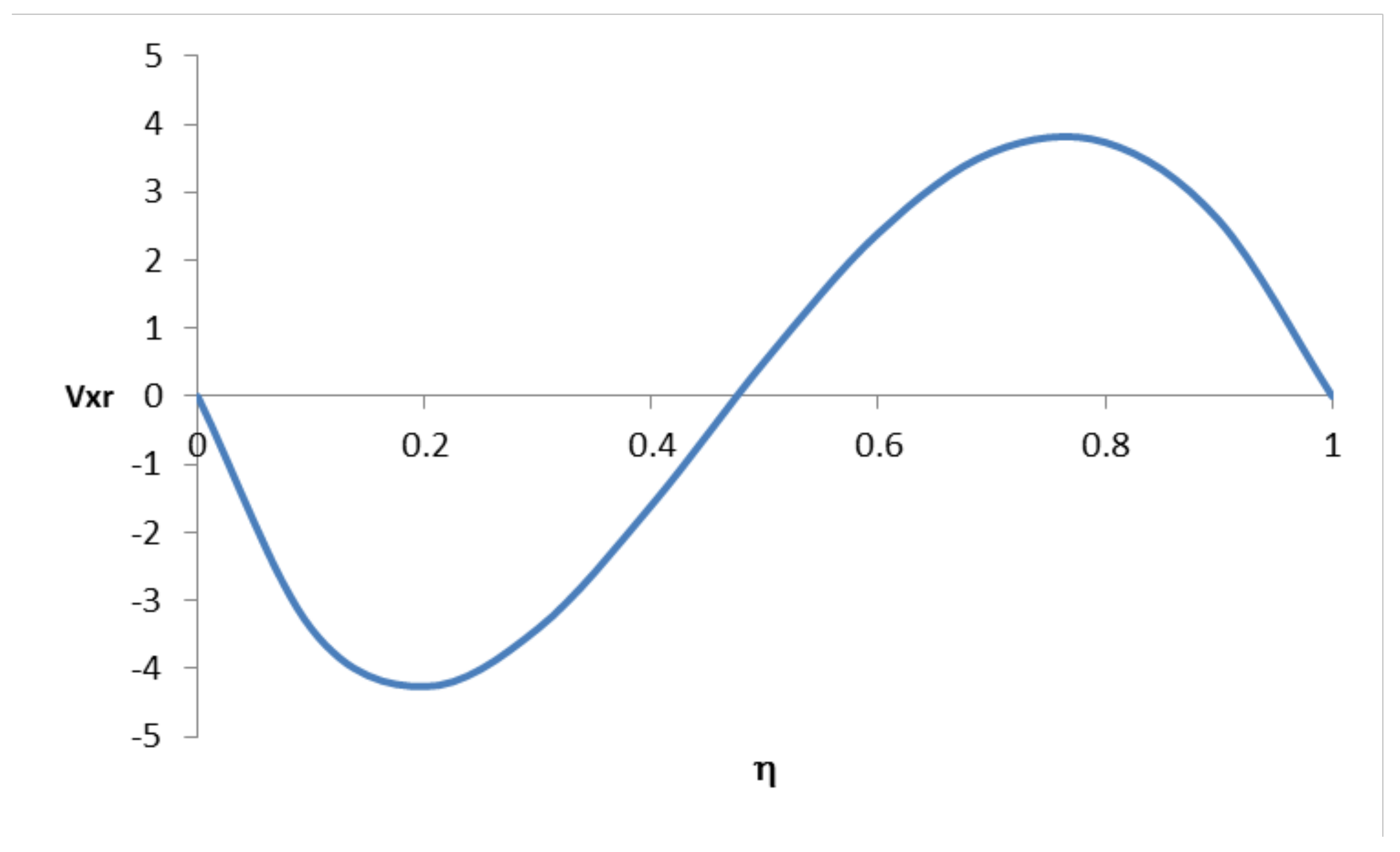
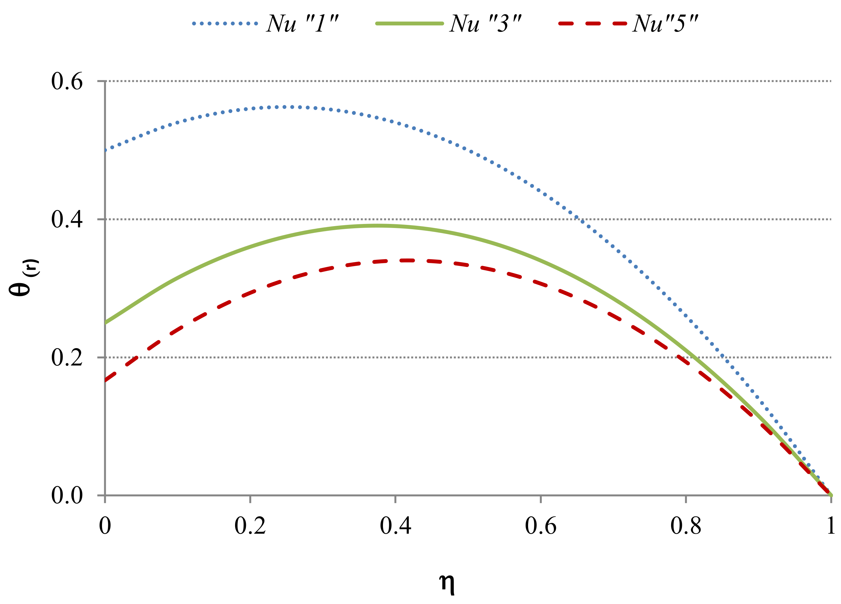
| 2 | 0 | F(R, Nu) = 2 | Adiabatic (limiting) case at the wall located at | The temperature located will be located at the boundary located at | The velocity profile will show two regions: one upward positioned near the boundary located at and the other one downward, located near the wall. at |
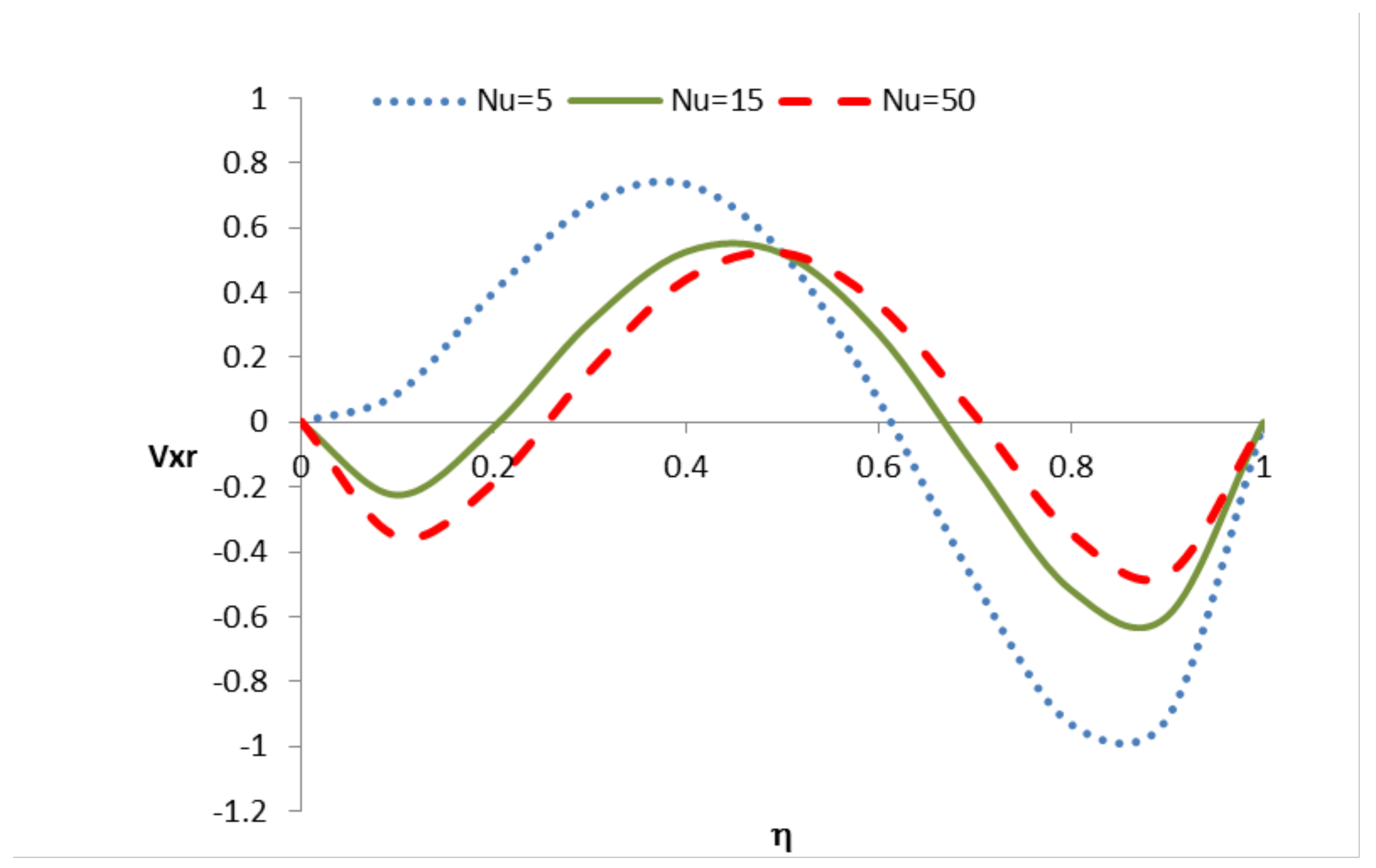
| 3 | ∞ | F(R, Nu) = Nu/(1 + Nu) | Well-mixed (limiting) case at the wall located at | The temperature at the wall located at will reach the environmental temperature | The velocity profile will show two regions: One upward located near at the wall at and the other downward located near the wall at |
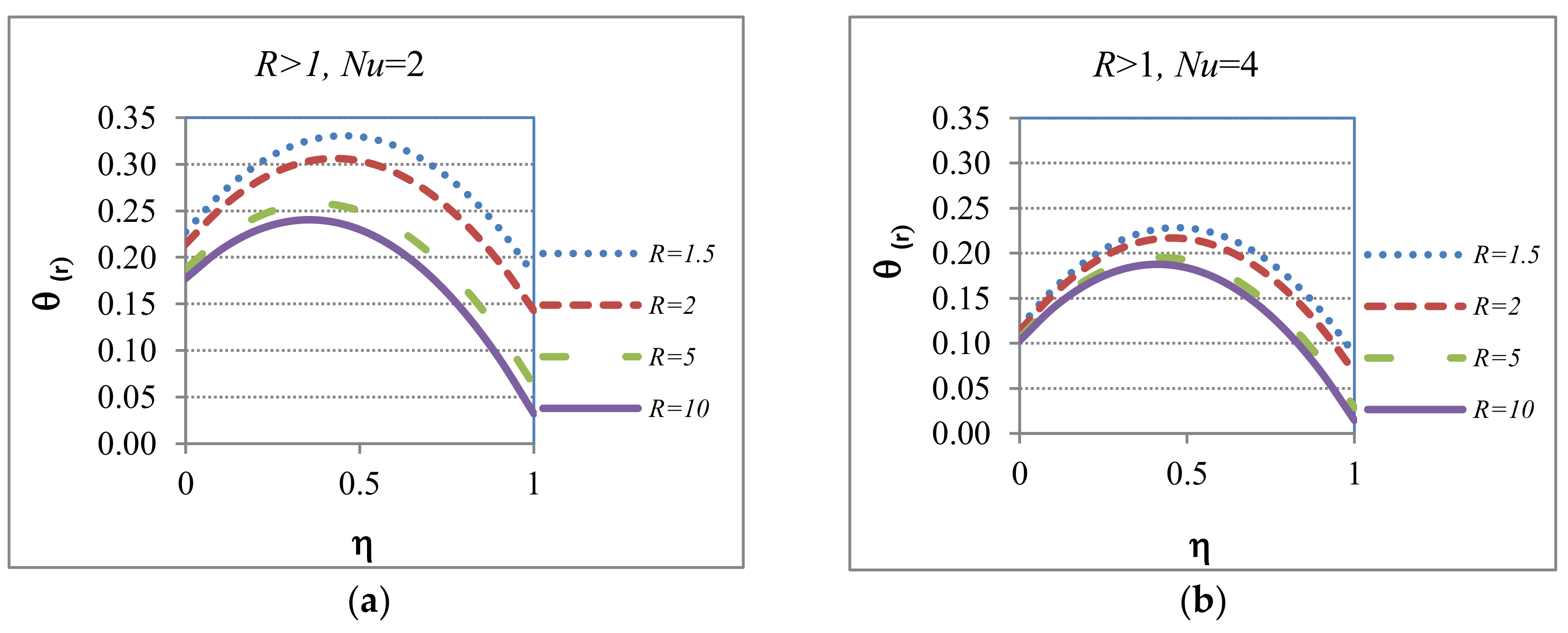
| 4 | R > 1 | General case where the boundary at has a “favorable” heat transfer rate than the one at | These cases will show temperature profiles similar to Case 3 but the temperature will not reach the environmental one | These cases will show hydrodynamic velocity profiles with behaviors between Case 1 and Case 3 | |
| 5 | R < 1 | General case where the boundary at has an “unfavorable” heat transfer rate than the one at | The general shape of the temperature profiles will follow Case 2 showing a “slower” heat transfer rate at | These cases will show hydrodynamic velocity profiles with behaviors between Case 2 and Case 1 |
© 2018 by the authors. Licensee MDPI, Basel, Switzerland. This article is an open access article distributed under the terms and conditions of the Creative Commons Attribution (CC BY) license (http://creativecommons.org/licenses/by/4.0/).
Share and Cite
Torres, C.M.; Arce, P.E.; Justel, F.J.; Romero, L.; Ghorbani, Y. Joule Heating Effects in Electrokinetic Remediation: Role of Non-Uniform Soil Environments: Temperature Profile Behavior and Hydrodynamics. Environments 2018, 5, 92. https://doi.org/10.3390/environments5080092
Torres CM, Arce PE, Justel FJ, Romero L, Ghorbani Y. Joule Heating Effects in Electrokinetic Remediation: Role of Non-Uniform Soil Environments: Temperature Profile Behavior and Hydrodynamics. Environments. 2018; 5(8):92. https://doi.org/10.3390/environments5080092
Chicago/Turabian StyleTorres, Cynthia M., Pedro E. Arce, Francisca J. Justel, Leonardo Romero, and Yousef Ghorbani. 2018. "Joule Heating Effects in Electrokinetic Remediation: Role of Non-Uniform Soil Environments: Temperature Profile Behavior and Hydrodynamics" Environments 5, no. 8: 92. https://doi.org/10.3390/environments5080092
APA StyleTorres, C. M., Arce, P. E., Justel, F. J., Romero, L., & Ghorbani, Y. (2018). Joule Heating Effects in Electrokinetic Remediation: Role of Non-Uniform Soil Environments: Temperature Profile Behavior and Hydrodynamics. Environments, 5(8), 92. https://doi.org/10.3390/environments5080092


