Article

Calcium Sulfoaluminate, Geopolymeric, and Cementitious Mortars for Structural Applications

1
Department of Materials, Environmental Sciences and Urban Planning, Università Politecnica delle Marche, via Brecce Bianche 12, Ancona 60131, Italy
2
School of Engineering, Università degli Studi della Basilicata, Viale dell’Ateneo Lucano 10, Potenza 85100, Italy
3
Institute of Atmospheric Sciences and Climate, National Research Council (ISAC-CNR), Via Gobetti 101, Bologna 40129, Italy
*
Author to whom correspondence should be addressed.
Environments 2017, 4(3), 64; https://doi.org/10.3390/environments4030064
Submission received: 27 July 2017 / Revised: 11 September 2017 / Accepted: 14 September 2017 / Published: 16 September 2017
(This article belongs to the Special Issue Environmentally Friendly Geopolymer Composites)

Abstract

:
This paper deals with the study of calcium sulfoaluminate (CSA) and geopolymeric (GEO) binders as alternatives to ordinary Portland cement (OPC) for the production of more environmentally-friendly construction materials. For this reason, three types of mortar with the same mechanical strength class (R3 ≥ 25 MPa, according to EN 1504-3) were tested and compared; they were based on CSA cement, an alkaline activated coal fly ash, and OPC. Firstly, binder pastes were prepared and their hydration was studied by means of X-ray diffraction (XRD) and differential thermal-thermogravimetric (DT-TG) analyses. Afterwards, mortars were compared in terms of workability, dynamic modulus of elasticity, adhesion to red clay bricks, free and restrained drying shrinkage, water vapor permeability, capillary water absorption, and resistance to sulfate attack. DT-TG and XRD analyses evidenced the main reactive phases of the investigated binders involved in the hydration reactions. Moreover, the sulfoaluminate mortar showed the smallest free shrinkage and the highest restrained shrinkage, mainly due to its high dynamic modulus of elasticity. The pore size distribution of geopolymeric mortar was responsible for the lowest capillary water absorption at short times and for the highest permeability to water vapor and the greatest resistance to sulfate attack.

1. Introduction

The quality of the environment is negatively affected by mortar and concrete production. In fact, huge amounts of natural resources are consumed and large quantities of pollutants are generated [1], including CO2 which originates from both fossil fuel combustion (about 40% of the total CO2 emissions) and limestone thermal decomposition occurring during cement manufacture [2,3]. The production of one ton of cement clinker emits approximately 0.87 tons of CO2 [4,5]. The contribution of the cement industry to global anthropogenic CO2 emissions is estimated to be as high as 7% [6].
In order to reduce CO2 emissions in the life cycle of mortars/concretes, several approaches [7,8,9,10] have been suggested, such as replacing virgin materials with industrial by-products [11,12,13,14], improving durability in order to reduce maintenance costs [15], and increasing the use of low-CO2 Portland cements and the development of alternative low-CO2 binders. As an example, low-CO2 cements can be produced by using non-carbonated CaO sources as a constituent of the Portland clinker-generating raw mix [16,17] or increasing the production of blended cements, obtained by mixing Portland clinker with significant amounts of supplementary cementitious materials based on silica and alumina (e.g., natural pozzolans, coal fly ashes, blast-furnace slags) [18,19].
Calcium sulfoaluminate (CSA) cements are special cements, namely hydraulic binders obtained from non-Portland clinkers. They are characterized by a high mechanical strength at early ages, rapid-hardening, high impermeability, and chemical resistance, as well as low drying shrinkage and solution alkalinity [20,21,22]. CSA cements have aroused the interest of the international cement research community not only for their technical properties, but also by virtue of the environmental sustainability of their manufacturing process which, compared to that of Portland cement, requires a lower synthesis temperature and limestone requirement, thus implying a reduced thermal input to the kiln and CO2 generation [23]. Moreover, another environmentally-friendly feature associated with CSA cement production is represented by the possibility of using several industrial by-products as raw materials in place of limestone, bauxite, and gypsum (e.g., coal fly ash, fluidized bed combustion residues blast furnace slag, flue gas desulfurization gypsum, phosphogypsum, incinerated municipal waste, red mud, anodization mud, alumina powder, and calcium looping spent sorbents [20,24,25,26,27,28,29,30,31,32]).
Another type of innovative binder is represented by geopolymers. They belong to alkali activated cements (AAC), which are obtained by the chemical reaction between a solid aluminosilicate precursor with an alkaline solution [33,34,35]. The main difference with AAC is that they are obtained by a precursor with an Al2O3 + SiO2 content higher than 80% and a very low CaO content [36]. A reduction of at least 40% of greenhouse gases emissions compared to that of Portland cement materials with the same characteristics has been estimated [37] thanks to the following reasons: the possibility of using industrial by-products such as fly ashes, or natural rocks calcined at very low temperatures (700–800 °C); the absence of limestone and a general energy saving in the production of geopolymers. Geopolymeric materials exhibit a high compressive strength, fast or slow setting, acid resistance, fire resistance, and low thermal conductivity compared to traditional Portland-based materials [38]. Despite this wide variety of attributes, these properties are deeply dependent on the raw materials and formulations used [33,39].
The aim of this work is to compare mortars belonging to the same strength class but manufactured with different binders that could ensure a more sustainable future for the construction materials sector. In particular, mortars based on a calcium sulfoaluminate cement and a fly ash-based geopolymeric binder were compared with those based on traditional ordinary Portland cement (OPC), as a reference. At first, the hydration of the three binders was investigated by means of X-ray diffraction (XRD) and differential thermal–thermogravimetric (DT-TG) analyses. Thereafter, the corresponding mortars, belonging to the structural class R3 ≥ 25 MPa (according to UNI EN 1504-3:2006), were tested and compared both in fresh (workability) and hardened states (microstructure, shrinkage, water vapor permeability, capillary water absorption, resistance to sulfate attack).

2. Materials and Methods

2.1. Materials and Paste/Mortar Mixes

In order to manufacture the geopolymeric binder, an Italian class F fly ash (FA) (specific surface area between 3000–7500 cm2/g, mean particle size of 10–30 μm) and calcium aluminate cement (CAC) (specific surface area between 2850–3450 cm2/g, mean particle size between 10–20 μm) were used as aluminosilicate precursors. The activating solution was prepared with a sodium silicate solution (SSS) and a potassium hydroxide solution. The SSS had a molar ratio SiO2/Na2O = 2.1 (SiO2 = 29.86 wt. %, Na2O = 14.64 wt. %), whereas for preparing the potassium hydroxide solution, KOH pellets (85% minimum assay) were dissolved in demineralized water.
For cementitious mixtures, Portland Cement CEM II/A-LL 42.5R (OPC) was used as a binder. The specific surface area and the mean particle size were 4200 cm2/g and 7 μm, respectively.
The CSA cement was supplied by an Italian cement manufacturer; its mineralogical composition, determined by means of the Rietveld method, and its Blaine fineness (Bf) are reported in Table 1.
Commercial calcareous sand with a maximum grain size of 8 mm was used for mortar preparation.
The chemical composition of powdered precursors and cementitious materials is given in Table 2.

2.1.1. Paste Preparation

In order to study the hydration mechanism and the hydration products, R3 OPC, R3 CSA, and R3 GEO pastes (water/binder ratio 0.50 by mass for both R3 OPC and R3 CSA and 0.23 for R3 GEO) were also prepared. Paste samples were investigated at a hydration time of 2, 7, 14, and 28 days. The samples were shaped as cylindrical discs (diameter of 30 mm and height of 15 mm) and placed in polyethylene bags inside a thermostatic bath at temperature (T) = 20 °C and relative humidity (RH) = 95%. At each hydration time, 10 g of paste was (a) gently pulverized in an agate mortar, (b) treated with acetone (to stop hydration) and diethyl ether (to remove water), (c) dried for 20 min at 40 °C, and (d) stored in a desiccator over silica gel-soda lime (to ensure protection against H2O and CO2).

2.1.2. Mortar Preparation

The cementitious (R3 OPC) and calcium sulfoaluminate (R3 CSA) mortars were prepared with a sand:cement:water ratio of 3:1:0.65 and 3:1:0.50 by weight, respectively.
The geopolymeric mortar (R3 GEO) was prepared with a sand/precursor ratio equal to 2.7 by weight and a water/binder (w/b) ratio of 0.23. In geopolymers, the binder is the sum of aluminosilicate powders and solids dissolved in the activating solution, namely KOH pellets in the potassium hydroxide solution and the amount of SiO2 and Na2O in the SSS.
The mix proportions of mortars are given in Table 3. R3 OPC and R3 CSA mortars were prepared according to UNI EN 1015-2:2007. Concerning R3 GEO, the activating solution was prepared 24 h prior to the cast for cooling at room temperature (T = 20 ± 1 °C) and for improving the polymerization process [40]. On the date of casting, aluminosilicates were dry mixed for 2 min, and the activating solution was then added and mixed for 3 min. The workability of mortars was measured according to UNI EN 1015-3:2007. Finally, the mortars were poured into various molds for the different tests and cured at RH = 90 ± 5% and T = 20 ± 1 °C for seven days and then at RH = 50 ± 5% and T = 20 ± 1 °C until testing, if not differently specified.

2.2. Methods

2.2.1. Hydration Analyses

2.2.1.1. X-ray Diffraction Analysis

X-ray diffraction (XRD) analysis was employed for the determination of the hydration products of pastes based on R3 OPC, R3 CSA, and R3 GEO. It was performed with a diffractometer (Cu Kα radiation and 0.02° 2θ s−1 scanning rate) operating between 5° and 60° 2θ and equipped with software for the spectra evaluation.

2.2.1.2. Simultaneous Differential Thermal–Thermogravimetric Analysis

Simultaneous differential thermal–thermogravimetric (DT-TG) analysis was carried out in 150 µL alumina crucibles with apparatus operating in dry airflow and a temperature range of 20–1000 °C (with a heating rate of 10 °C min−1).

2.2.2. Tests for Mechanical Properties

The flexural strength (Rf) and compressive strength (Rc) of mortars were measured after 2, 7, and 28 days of curing on 40 × 40 × 160 mm specimens, according to UNI EN 1015-11:2007.
After 28 days, the dynamic modulus of elasticity (Ed) was also evaluated for three prismatic specimens (40 × 40 × 160 mm) according to UNI EN 12504-4:2005. Equation (1) gives the formula used to calculate Ed:
E d = v 2 ρ [ ( 1 + γ d ) ( 1 2 γ d ) ] ( 1 γ d )
where v is the velocity of the ultrasonic pulse (m/s), ρ is the hardened density of the mortar (kg/m3), and γd is the Poisson’s modulus. The Poisson’s modulus, equal to 0.20 for all mortars, was estimated as the average value between 0.15 and 0.25 reported in the literature for cementitious materials [41] (p. 200).
After 28 days of curing, the determination of the adhesive strength of substrates was performed for five cylindrical mortar specimens (diameter of 50 mm and height of 10 mm) and the average value was recorded in accordance with UNI EN 1015-12:2002. The substrate chosen was a red clay brick measuring 250 × 120 × 55 mm.

2.2.3. Microstructural Analyses

The pore structure of mortars was studied by mercury intrusion porosimetry (MIP) after 28 days.
The morphology of mortars was investigated by scanning electron microscopy (SEM) after 28 days of curing on small pieces of graphite coated mortar specimens.

2.2.4. Drying Shrinkage Tests

The free drying shrinkage was measured on three prismatic specimens (40 × 40 × 160 mm) for each mortar according to UNI EN 12617-4:2003 for 56 days and the percentage of weight loss caused by water evaporation was also recorded.
In addition, the restrained shrinkage was measured on three prismatic specimens (50 × 50 × 250 mm) according to UNI EN 8147:2008.
For both free and restrained drying shrinkage tests, specimens were exposed to T = 20 ± 1 °C and RH = 90 ± 5% for the first day after the cast, and then to T = 20 ± 1 °C and RH = 50 ± 5%.

2.2.5. Water Vapor Permeability Test

A good water vapor permeability is positive for mortars, since it ensures both the proper drying of the internal water and the elimination of water vapor that occurs within buildings [42]. Water vapor permeability measurements were carried out according to UNI EN 1015-19:2007 on three cylindrical specimens (diameter of 140 mm and height of 30 mm) after 28 days of curing. The test was performed at RH = 50 ± 5% and T = 20 ± 1 °C. The mass loss due to water evaporation through the specimen was measured during time and the results were expressed in terms of the water vapor diffusion resistance factor (μ).

2.2.6. Capillary Water Absorption Test

Water capillary absorption is an essential test to determine the durability of construction materials [43,44,45,46,47,48,49], since many aggressive ions, like Cl or SO42−, can penetrate through water. The water absorbed per unit area (Qi) and capillary water absorption coefficient (AC) were measured according to UNI EN 15801:2010. For each mortar type after 28 days of curing, three cubic specimens (40 mm) were dried at T = 60 ± 2 °C until a constant weight was reached and then tested, and the average values obtained were reported.

2.2.7. Test for Resistance to Sulfate Attack

To determine the durability of mortars in aggressive solutions, prismatic specimens (40 × 40 × 160 mm) were partially immersed (40 mm) in water (one specimen as reference) and in 14 wt. % Na2SO4 solution (two specimens) after 28 days of curing for a period of 21 days. The level of the solution was kept constant by adding only water for replacing the evaporated amount. At first, specimens were dried at T = 60 ± 2 °C until constant weight was reached, and the resistance to sulfate attack was then visually investigated by evaluating the formation of possible cracks and efflorescence.

3. Results and Discussion

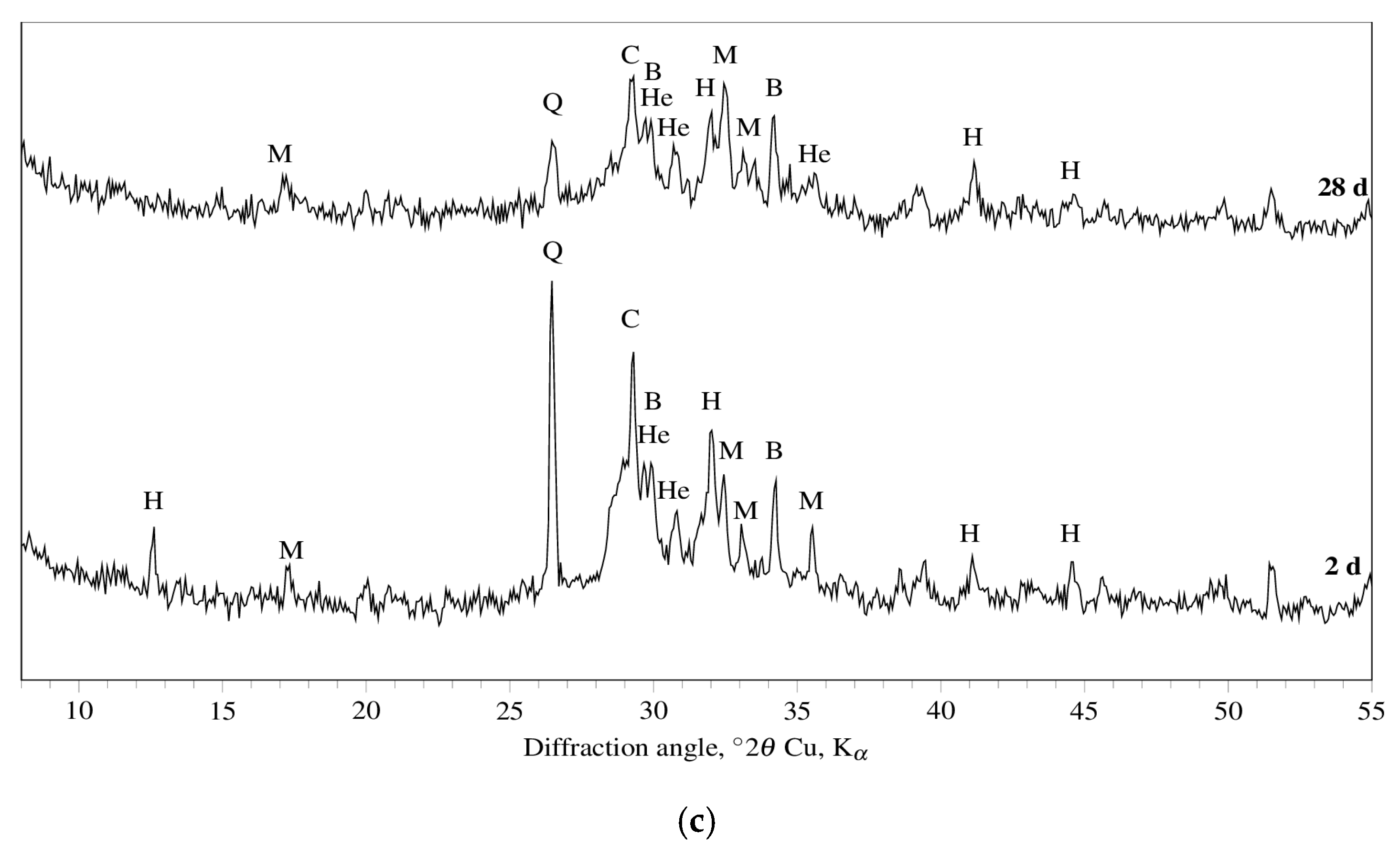
3.1. Hydration of Binder Pastes

The DT-TG results for R3 OPC, R3 CSA, and R3 GEO pastes, aged up to 28 days, are shown in Figure 1. As far as R3 OPC and R3 CSA cement pastes are concerned, the DT-TG apparatus was able to identify [50] ettringite, monosulfate, calcium hydroxide, and calcium carbonates through the following dehydration endothermal peaks: 151 ± 9 °C; 197 ± 3 °C; 509 ± 3 °C; and 794 ± 5 °C, respectively. In particular, from an overall examination of the obtained results, it can be concluded that:
  • ettringite (3CaO·Al2O3·3CaSO4·32H2O) and calcium hydroxide (which undergo a partial carbonation) are observed for the R3 OPC;
  • ettringite is detected at all investigated curing periods in the R3 CSA system, while a monosulfate peak appears only after seven days of hydration.
Finally, it can be argued that: (i) calcium silicate hydrates are the main hydration products of the calcium silicates present in the Portland clinker (a process that yields Ca(OH)2 as the by-product); (ii) ettringite can be formed through the hydration of calcium hydroxide-alumina-calcium sulfate systems in OPC and through the hydration of calcium sulfoaluminate (4CaO·3Al2O3·CaSO4) with calcium sulfate in CSA systems; iii) monosulfate (3CaO·Al2O3·CaSO4·12H2O) can be regarded as the decomposition product of ettringite.
Regarding R3 GEO pastes, the DT-TG technique was mainly used for the evaluation of the dehydration of adsorbed water. All DT curves are very similar to each other showing a broad endothermic peak (141 ± 4 °C) related to the loss of the absorbed water. An endothermic shoulder (182 ± 2 °C), due to the evaporation of “zeolitic” or “interstitial” [51] water, is found in the samples cured for 14 and 28 days. The presence of calcium carbonate is also recognized by both DT (727 ± 2 °C) and TG at all investigated curing periods.
The DT-TG results are confirmed by those obtained by XRD analysis. Figure 2 shows the XRD patterns of R3 OPC, R3 CSA, and R3 GEO pastes cured for two and 28 days. Peaks of portlandite (Ca(OH)2, main component) and ettringite (secondary component) as hydration products, and alite (3CaO·SiO2, only at two days of curing), belite (2CaO·SiO2), and calcite (CaCO3) as raw Portland cement materials, are observed. With reference to the hydration products of R3 CSA, ettringite represents the main phase after just two days of curing, whereas monosulfate only appears at 28 days of curing. Concerning the still anhydrous phases, dicalcium silicate and calcite do not show any significant change in their XRD signals.
XRD patterns of R3 GEO have confirmed its amorphous structure as one of the major characteristics. However, crystalline phases such as quartz (SiO2) and mullite (3Al2O3·2SiO2), both coming from the fly ash, sodium bicarbonate (coming from the Na-based activator), and hydroxisodalite (Na6Si6Al6O24·8H2O) and herschelite [(Na,Ca,K)AlSi2O6·3H2O], both corresponding to zeolite structures, are identified.

3.2. Fresh Properties of Mortars

Flow values of the mortars are reported in Table 4. The results show that R3 OPC and R3 CSA obtain the typical workability of stiff mortars (flow value ≤ 140 mm), whereas R3 GEO obtains the typical workability of plastic mortars (flow value > 140 mm). Despite the R3 GEO mortar being prepared with a lower amount of water, it is more workable than the above-mentioned mortars thanks to the spherical shape of fly ash particles.

3.3. Mechanical Properties of Mortars

Figure 3 shows the flexural (Rf) and compressive (Rc) strengths of R3 OPC, R3 CSA, and R3 GEO mortars during the first 28 days of curing.
The flexural strength of R3 OPC and R3 CSA mortars increases very fast after just two days of curing, reaching 65% of their final strength on the seventh day (Figure 3a). After 28 days of curing, the Rf of the calcium sulfoaluminate mortar is around 5.8 MPa and that of the cementitious one reaches 7.6 MPa. Conversely, R3 GEO reaches its ultimate flexural strength after the first week of curing, which then remains equal to 5.0 MPa and lower than those of the other two mortars.
The compressive strength of R3 OPC confirms the results obtained under flexure, registering an elevated strength development after seven days of curing equal to 80% of the final strength (Figure 3b). Additionally, R3 CSA reaches the maximum strength after only one week (39 MPa), but it incurs a strength loss at 28 days (36 MPa). The most gradual strength development is shown by the geopolymeric mortar R3 GEO with an Rc enhancement equal to 40% from seven to 28 days. This behavior is due to the fact that the reaction mechanism of fly ash and thus the reorganization of the geopolymeric gel is continuous during ageing and leads to strength gaining, even after long periods of time (180 days) [52].
The elevated compressive strength gained by the R3 CSA mortar after just seven days of curing is related to the formation of ettringite [21,53,54,55], which is the principle hydration product in calcium sulfoaluminate matrices. The morphology of ettringite crystals is influenced by the availability of space and the concentration of Ca2+ and SO42− ions [28,56]. In solutions with a low concentration of Ca(OH)2 and great availability of space, ettringite assumes an elongated acicular shape, which increases the mechanical strength of the compound. In solution with a high concentration of Ca(OH)2 and with a low availability of space, ettringite appears as small prismatic crystals able to absorb water and to swell [57] (p. 52). The reduction of Rc from seven to 28 days is related to the great compactness of the mortar, which hinders the proper growth of ettringite crystals and causes the micro-cracking of the matrix [56] (see Section 3.4).
The dynamic modulus of elasticity measured after 28 days of curing is reported in Table 4.
The results show that at the same strength class R3 OPC and R3 CSA obtain Ed values 35% higher than that of R3 GEO. The low stiffness of the geopolymeric mortar is in accordance with the literature [58,59,60,61,62,63,64]. A lower stiffness means lower induced tensions at a certain deformation and, therefore, a lower probability of cracking caused by tensile (or shear) stresses or expansive reactions. Moreover, mortars with low stiffness are more mechanically compatible with the substrate of old buildings.
After 28 days from the date of casting, the adhesion on red clay bricks was investigated and the average results are reported in Table 4. The highest strength is obtained by the R3 CSA mortar; its value is 20% higher than that obtained by the cementitious sample (R3 OPC). On the contrary, the lowest result is registered by the geopolymeric mortar. Its fu is 70% and 75% lower than that of R3 OPC and R3 CSA, respectively. The low adhesion of the geopolymeric mortar is in accordance with a previous work conducted by the authors [58].

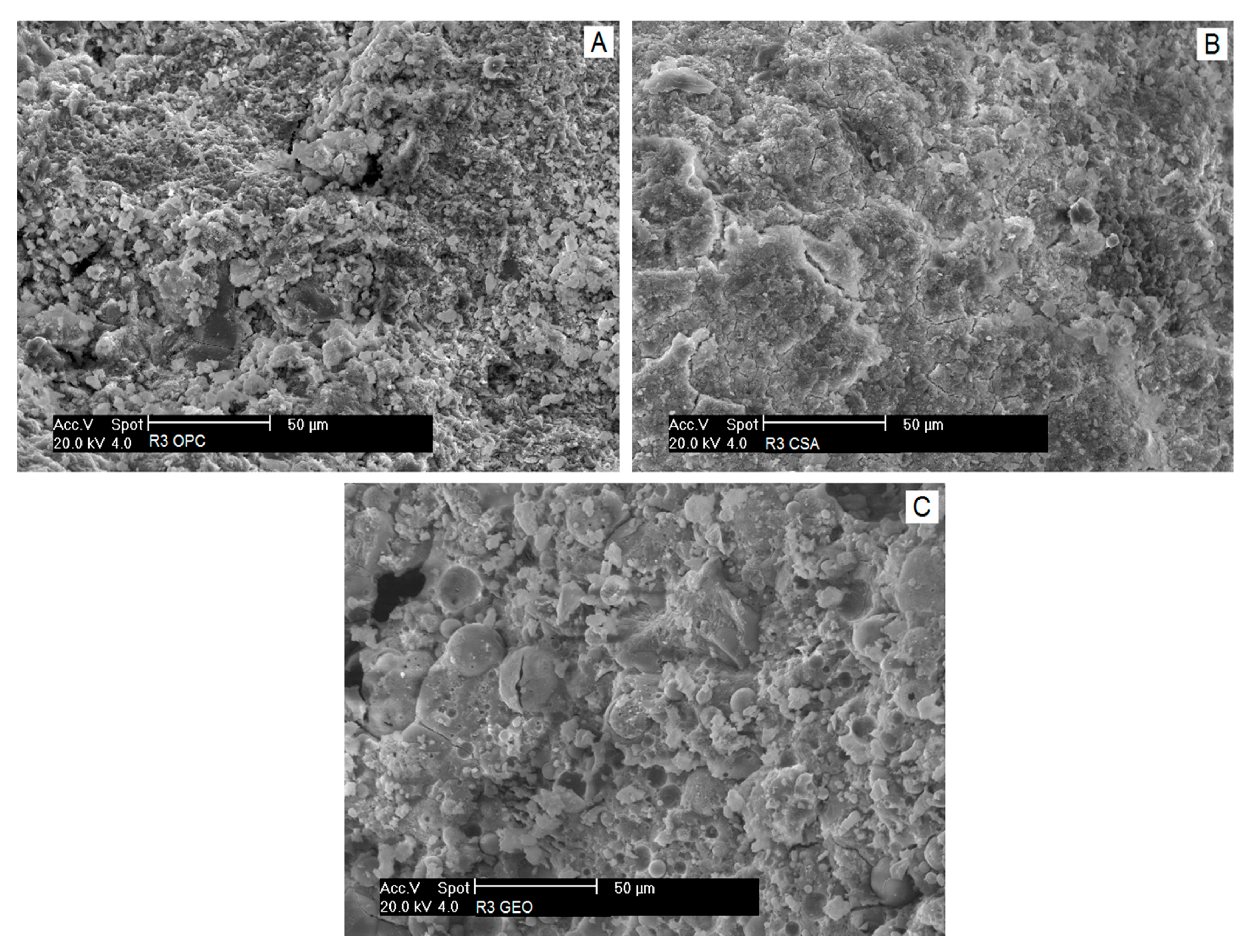
3.4. Microstructural Analyses of Mortars

The total porosity (Vp) of mortars is given in Table 4. At the same mechanical strength class, the OPC mortar shows the highest total porosity (18%), whilst conversely, CSA and GEO are characterized by the lowest Vp (13%). The lower total porosities of these two mortars compared to the cementitious one are related to their lower w/b ratios (Table 3), hence to the lower presence of free water that can evaporate during the curing process.
The pore distribution of mortars is reported in Figure 4. A general pore size classification is given by the International Union of Pure and Applied Chemistry (IUPAC), where pores are divided into micropores (d < 1.25 nm), mesopores (1.25 nm ≤ d ≤ 25 nm), macropores (25 nm ≤ d ≤ 5000 nm), and entrained air voids, entrapped air voids, and pre-existing microcracks (5000 nm ≤ d ≤ 50,000 nm). It is evident that there is a great difference between the two cementitious mortars R3 OPC and R3 CSA, which both show a unimodal pore distribution with average diameters of around 100 and 35 nm, respectively, and the R3 GEO mortar where the pore distribution has a polymodal trend, with pores smaller than 15 nm and larger than 1 μm.
Moreover, both R3 CSA and R3 GEO show the highest fraction of pores with small diameters compared to R3 OPC.
The microstructure of mortars investigated by SEM is given in Figure 5.
R3 OPC (Figure 5a) shows the typical cementitious microstructure rich in tricalcium silicate (C3S) grains bonded together at the acicular C–S–H hydration products. The microstructure of R3 CSA (Figure 5b) appears similar to R3 OPC; however the acicular ettringite crystals are not visible and the surface of the specimen is surrounded by a dense net of cracks. The absence of visible ettringite crystals can be explained by the great compactness of the matrix that has hindered the proper formation of the needle-like structure of ettringite and has favored the formation of small prismatic crystals, able to absorb water, to swell [57] (p. 52) and to induce tensile stresses in the paste because of its highly expansive behavior [56]. A recent study [65] reports that the decomposition of ettringite also only occurs after heating CSA samples at a temperature above 60 °C, which causes the loss of approximately 20 water molecules per formula and the transition of ettringite to an amorphous state, according to Hartman et al. [66].
Figure 5c shows an SEM image of R3 GEO, which is characterized by small spherical particles of unreacted fly ash surrounded by a dense and continuous aluminosilicate mass. Semispherical voids, namely imprints of fly ash cenospheres probably migrated within the paste, are also detectable.

3.5. Shrinkage and Weight Loss of Mortars

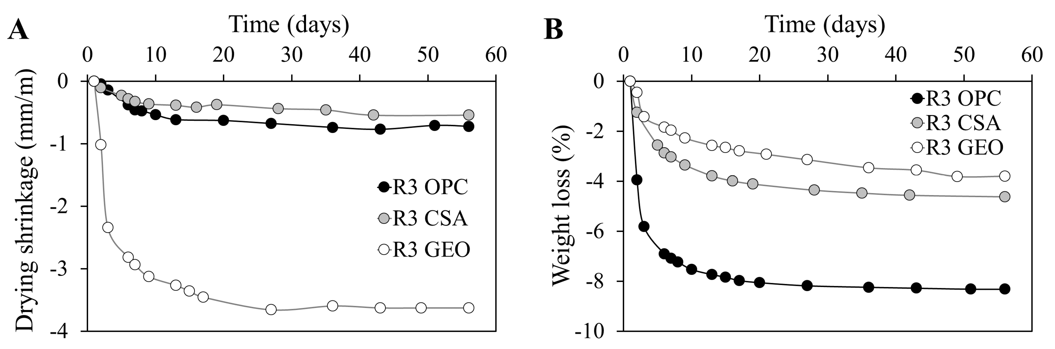
3.5.1. Drying Shrinkage and Weight Loss

Drying shrinkage and weight loss due to water evaporation are given in Figure 6. Drying shrinkage depends on: open porosity, which facilitates water evaporation; pore distribution, because the finer the capillary network, the higher the capillary stress that generates shrinkage [67]; and elastic modulus of the paste, since the lower the stiffness, the higher the shrinkage which generates the presence of the same stress.
As expected, the higher porosity of the R3 OPC mortar (Table 4) causes a higher water loss (Figure 6b), which is two times higher than the values of R3 CSA and R3 GEO after two months of curing. The great water loss of the cementitious mortar is related to the higher presence of water used for the mix design, for which a higher amount of free water evaporated during the test. However, the highest free drying shrinkage is registered for the geopolymeric mortar R3 GEO, which is 85% higher than the values of the other two mortars (Figure 6a), according to the literature [58,59,60,68], whereas the lowest one is shown by R3 CSA [53,69]. This effect is due to two aspects: on one hand, R3 GEO is characterized by the highest percentage of pores with small diameters (around 15 nm, see Figure 4); on the other hand, its dynamic modulus of elasticity is the lowest. The former aspect has contributed to the highest capillary stresses within the paste for water evaporation, whereas the latter has emphasized the shrinkage related to those stresses. Moreover, the lowest drying shrinkage of the R3 CSA mortar is related to the expansion given by the ettringite formation. It is known that the hydration of ye’elimite results in the ettringite formation, which is the first cause of expansion in CSA cements [70]. However, the rate of expansion in the CSA system is governed by several aspects, such as the C4A3Ŝ content, calcium sulfate content, w/c ratio, etc. In particular, in systems with a medium amount of sulfoaluminate phase (around 40% as in the present work), the expansion occurs at early ages and lasts after the first 32 h, whereas in systems with the same w/c ratio but a higher C4A3Ŝ content (more than 50%), the expansion conversely continues after four days [71]. The initial, even if limited, expansive behavior of R3 CSA (not visible in Figure 6a) has then mitigated the drying shrinkage of the CSA mortars [72].

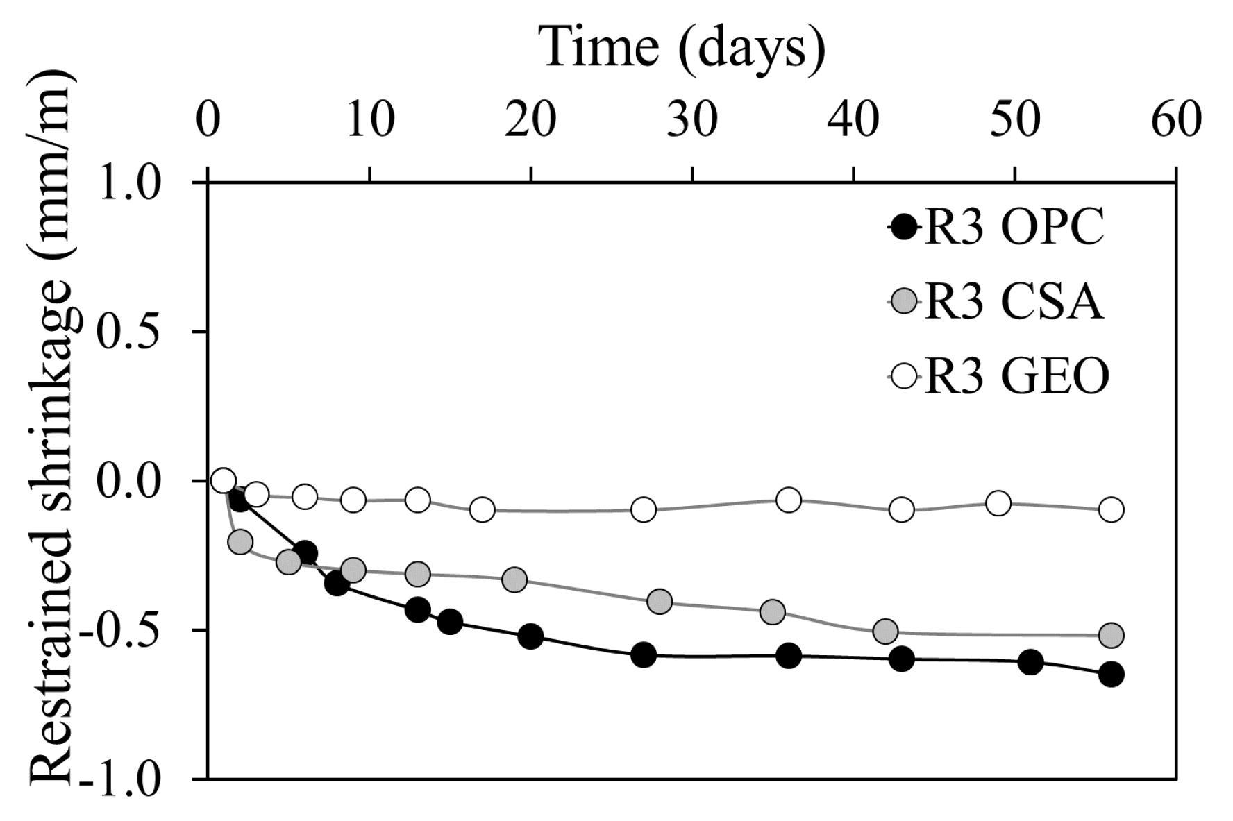
3.5.2. Restrained Shrinkage

Restrained shrinkage (Figure 7) confirms the free drying shrinkage results. In fact, the highest deformations are registered by both calcium sulfoaluminate cement mortar and ordinary Portland cement mortar, while the geopolymeric specimen does not show any modification of the embedded rebar. It is known that a low restrained shrinkage is related to a low modulus of elasticity [73] and/or large creep relaxation [41] (p. 203). R3 OPC and R3 CSA, with their very high Ed, have induced the highest shrinkage deformations in the embedded rebar, whereas the low modulus of elasticity of the R3 GEO mortar is not sufficient to reduce the length of the steel bar. As for drying shrinkage, the initial expansion of the R3 CSA mortar (not visible in Figure 7, since it occurs throughout the first hours) mitigates the rate of the restrained shrinkage, causing a lesser effect compared to that of the R3 OPC.

3.6. Water Vapor Permeability of Mortars

Permeability depends on open porosity, connected pores size, connectivity, and tortuosity of the microstructure. Moreover, according to Katz and Thompson’s relation, the greater the threshold pore diameter, the higher the permeability of the material [74].
The results show that the R3 OPC mortar is the least permeable, with a water vapor diffusion resistance factor (μ) equal to 21 (Table 5). On the contrary, R3 GEO is the most prone to water vapor permeability [58,59,60] since it obtains a μ value of 9. The higher permeability of the geopolymeric mortar is a direct consequence of the elevated fraction of pores with large diameters (Figure 4) which ensure the highest transpiration of the specimen. Conversely, the lower μ value measured for the R3 CSA mortar compared to that of R3 OPC could be related to the presence of microcracks within the paste formed during the hardening process (Figure 5), since neither the total porosity (Table 4) nor the pore dimensions (Figure 4) are higher than those of R3 OPC.

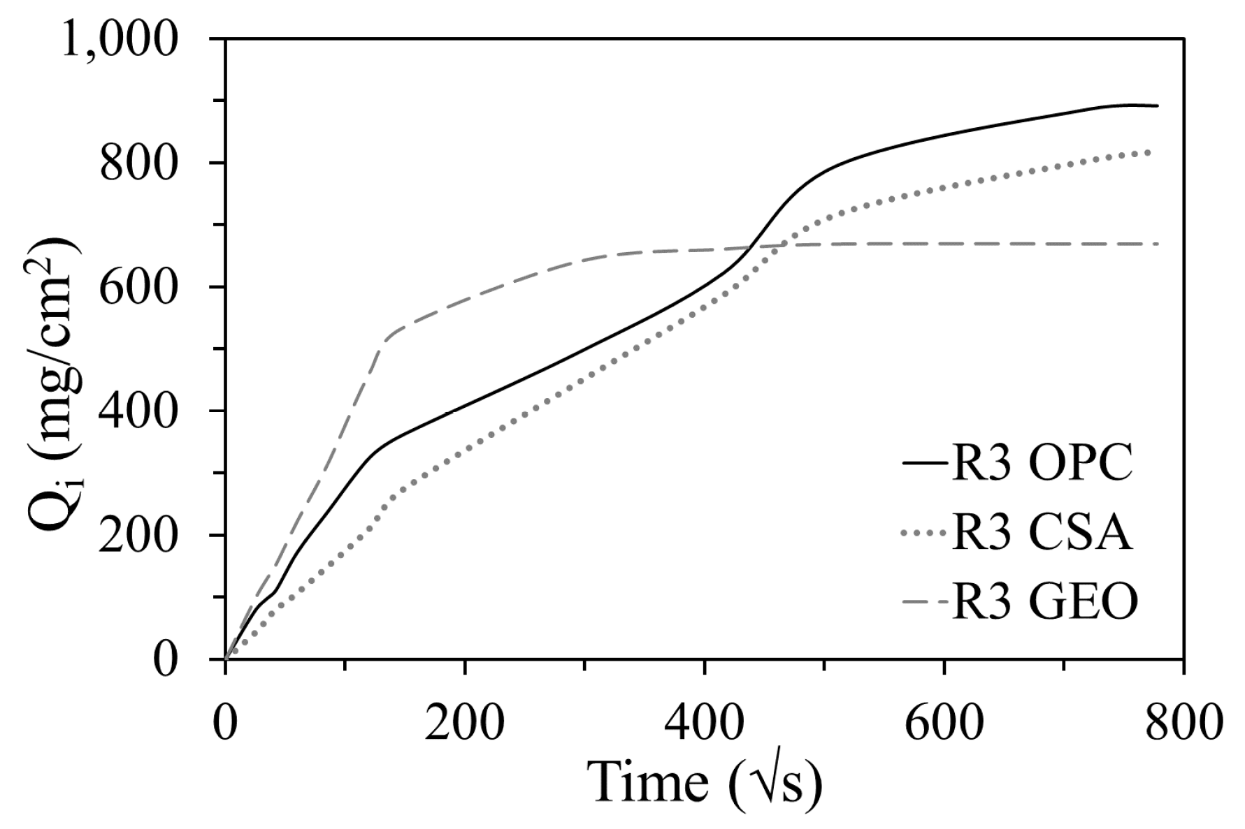
3.7. Capillary Water Absorption of Mortars

The capillary water absorption coefficient (AC) is reported in Table 5. A higher value of AC means a faster water uptake of the specimen, thus a high fraction of pores with large diameters. The R3 GEO mortar shows the greatest value of the coefficient compared to the other two types of mortars, since its pore distribution is characterized by the highest fraction of pores with large diameters (Figure 4). The water capillary absorption of R3 OPC is 37% lower than that of R3 GEO and the AC of R3 CSA reaches half the value of that of the geopolymeric one. This behavior is due to the critical pore radius that is smaller in the calcium sulfoaluminate mortar than in the mortar prepared with ordinary Portland cement (Figure 4).
Figure 8 gives the water absorbed per unit area (Qi) by the mortars for a period of eight days. The results show that the trend of R3 GEO is different to those of the other two mortars; in fact it absorbs more water during the first half hour and reaches saturation earlier, but the total amount of water absorbed is lower [34,58,60]. The first linear part of the Qi curve corresponds to the saturation of the capillary pores with higher diameters, whereas the second (non-linear) part corresponds to the saturation of the smaller ones [75]. Therefore, in the geopolymeric mortar, the higher water uptake during the first thirty minutes is related to the higher fraction of capillary pores of a greater size (Figure 4), while the lower absorbed water at the end of the test is related to the lower total porosity (Table 4) and to the presence of large pores (>1 µm, Figure 4). The other two mortars show a similar Qi trend, where the lowest water absorption is obtained by R3 CSA because of its lower porosity.

3.8. Resistance to Sulfate Attack of Mortars

Figure 9 shows images of mortar specimens just after the extraction from the containers after 21 days of semi-immersion. The cementitious mortar (R3 OPC) shows evident efflorescence formation due to the crystallization of sodium sulfate salt (Figure 9a). In the reference specimen, efflorescence is not visible.
A similar effect is showed by the R3 CSA mortar, where efflorescence is produced on the upper part of the two specimens semi-immersed in the aggressive solution (Figure 9b). However, unlike the R3 OPC mortar, these specimens undergo a slight degradation of the external surfaces due to the expansive salt crystallization that cause higher tensile stresses because of the higher fraction of pores with small diameters (Figure 4).
The R3 GEO mortar shows a high resistance to sulfate attack with efflorescence formation barely visible (Figure 9c) [60]. Moreover, the reference mortar remains unchanged. The high concentration of the activating solution has caused a high densification of the geopolymeric paste and the formation of a structure with a low porosity (Table 4). Even if R3 CSA and R3 GEO share the same Vp value (Table 4), the higher fraction of large pores in the geopolymeric mortar (Figure 4) hinders a large water suction (Figure 8) and thus the ingress of sodium sulfate ions.

4. Conclusions

In this work, two environmentally-friendly mortars prepared with calcium sulfoaluminate cement and by the alkaline activation of a coal fly ash at room condition (RH = 90 ± 5% and T = 20 ± 1 °C for the first week of curing and then at RH = 50 ± 5% and T = 20 ± 1 °C until testing) were compared with one based on ordinary Portland cement of the same mechanical strength class (R3 ≥ 25 MPa, according to UNI EN 1504-3:2006).
At the same strength class:
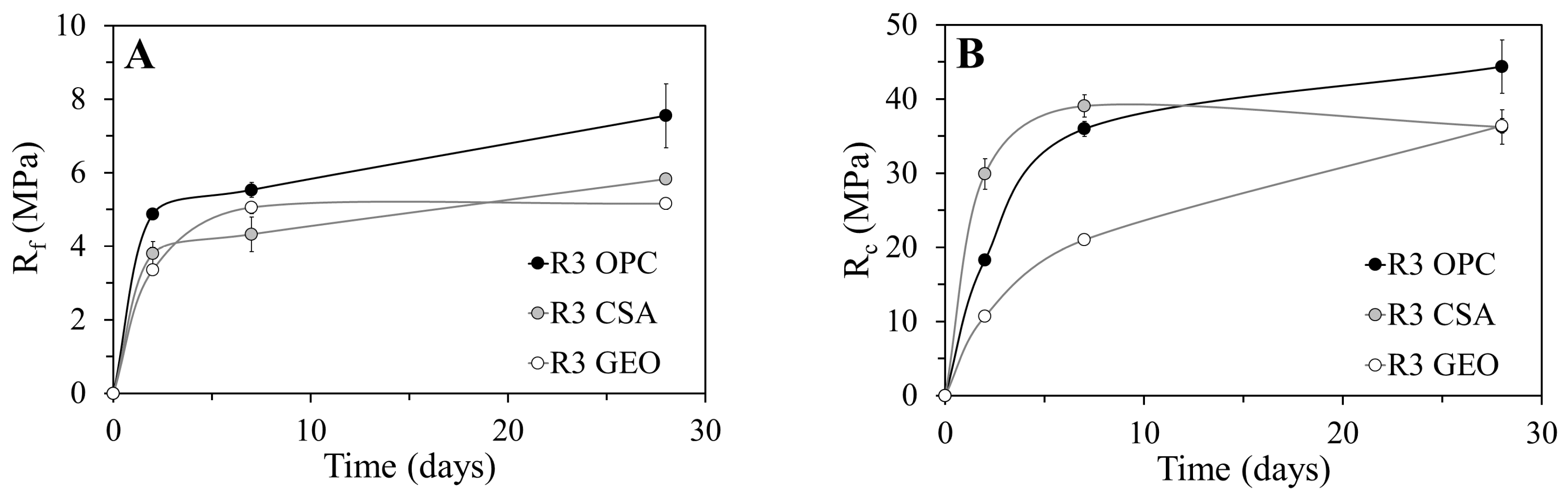
  • the ultimate compressive strength is reached earlier in R3 OPC and R3 CSA mortars than in the R3 GEO mortar, since the reaction mechanism, and thus the strength development, of fly ash geopolymer is continuous during time;
  • the dynamic modulus of the geopolymeric mortar is 35% lower than those of the other two cementitious mortars;
  • The highest stiffness of R3 OPC and R3 CSA mortars ensures an 85% lower drying shrinkage, but an 80% higher restrained shrinkage compared to the R3 GEO mortar. Moreover, the expansive reaction due to ettringite formation mitigates the drying shrinkage of the R3 CSA mortar.
The pore size distribution and the total porosity of mortars influence the results as follows:
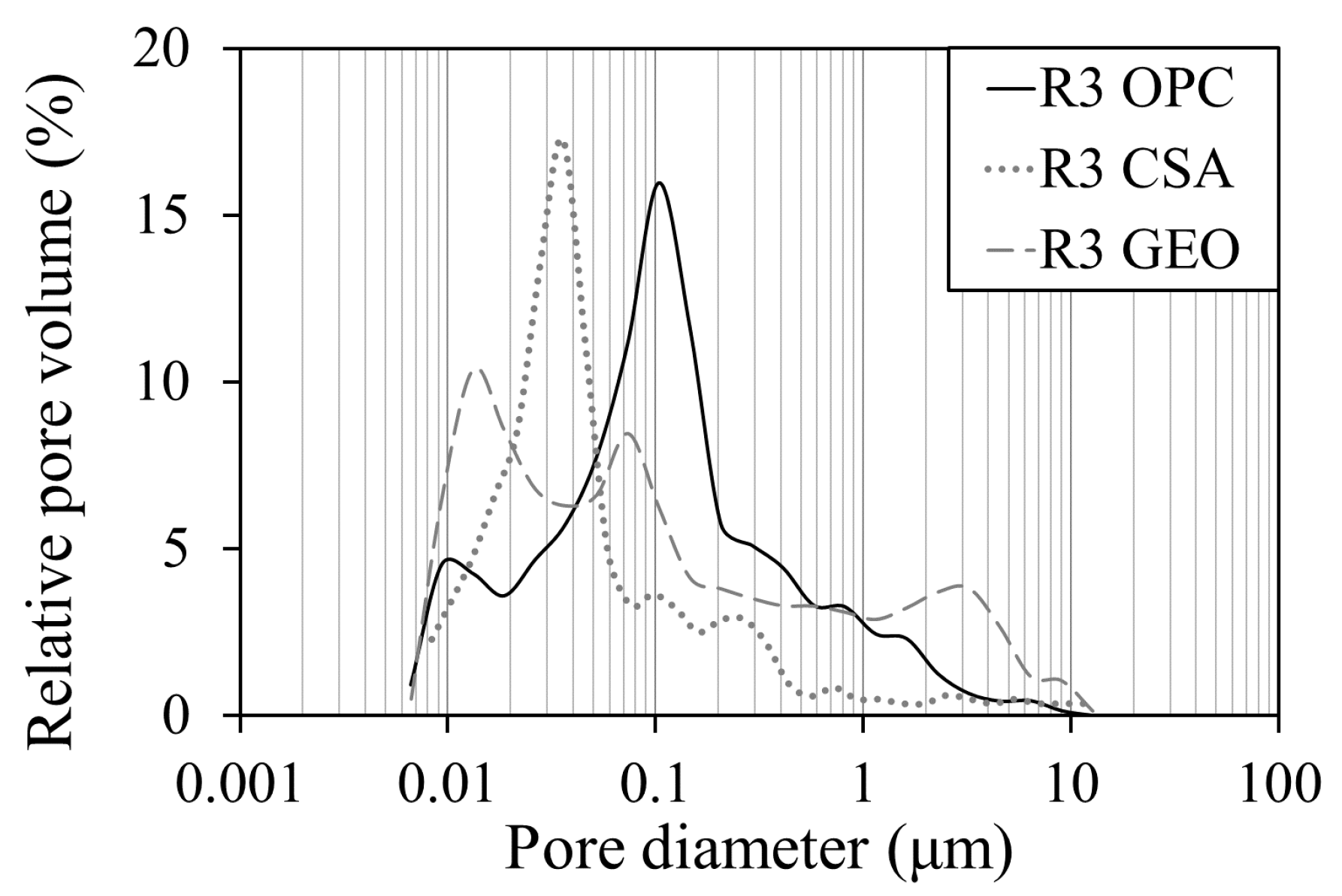
  • the geopolymeric mortar is the most resistant to a solution prepared with 14 wt. % of Na2SO4, since the low porosity and the presence of large pores hinder the water suction and thus the ingress of aggressive ions;
  • the highest fraction of pores with large diameters in the R3 GEO mortar gives a permeability to water vapor that is 40% and 57% higher than that of R3 CSA and R3 OPC mortars, respectively;
  • the low porosity and the high fraction of capillary pores with small diameters ensures the lowest water uptake in short periods of time for the R3 CSA mortar, whereas the low porosity of the R3 GEO mortar results in the lowest absorption over long periods of time because of the high fraction of pores with large diameters.
This experimentation has highlighted that the use of fly ash-based geopolymers is preferable for structures that need a higher permeability to water vapor, a low aptitude to capillary water absorption, and a high resistance to sodium sulfate attack. On the contrary, mortars based on OPC and CSA can be used as repairing materials for cementitious structures thanks to their similar moduli of elasticity and to the very high dimensional stability.

Acknowledgments

The authors would like to express their gratitude to Alessandro Pasqualini of General Admixture S.p.A. (Ponzano Veneto, Italy) and Mirko Braga of Ingessil S.r.l. (Verona, Italy) to have kindly offered the fly ash and the sodium silicate solution used in this study, respectively.

Author Contributions

Alessandra Mobili performed the materials characterization and the mix design of mortars. She tested the workability, the mechanical properties, the microstructure, the drying shrinkages and interpreted the data. She drafted the manuscript. Alberto Belli performed the capillary water absorption, the water vapor permeability and the resistance to sulfates tests. Chiara Giosuè interpreted the drying shrinkages, the capillary water absorption, the resistance to sulfates and the water vapor permeability data and edited the manuscript. Antonio Telesca and Milena Marroccoli performed the chemical and mineralogical analysis of CSA cement, prepared the mix design of pastes and performed the DT-TG and XRD analyses, interpreted the data, drafted the “Hydration of binder pastes” section and edited the manuscript. Francesca Tittarelli coordinated and supervised the project, the analysis of the data, and drafted and edited the manuscript. All authors read and approved the final manuscript.

Conflicts of Interest

The authors declare no conflict of interest.

References

  1. Ozga, I.; Ghedini, N.; Giosuè, C.; Sabbioni, C.; Tittarelli, F.; Bonazza, A. Assessment of air pollutant sources in the deposit on monuments by multivariate analysis. Sci. Total Environ. 2014, 490, 776–784. [Google Scholar] [CrossRef] [PubMed]
  2. Telesca, A.; Marroccoli, M.; Ibris, N.; Lupiáñez, C.; Díez, L.I.; Romeo, L.M.; Montagnaro, F. Use of oxyfuel combustion ash for the production of blended cements: A synergetic solution toward reduction of CO2 emissions. Fuel Process. Technol. 2017, 156, 211–220. [Google Scholar] [CrossRef]
  3. Xu, D.; Cui, Y.; Li, H.; Yang, K.; Xu, W.; Chen, Y. On the future of Chinese cement industry. Cem. Concr. Res. 2015, 78, 2–13. [Google Scholar] [CrossRef]
  4. Mehta, P.K.; Monteiro, P.J.M. Concrete: Microstructure, Properties, and Materials, 3rd ed.; McGraw-Hill: New York, NY, USA, 2006. [Google Scholar]
  5. Barcelo, L.; Kline, J.; Walenta, G.; Gartner, E. Cement and carbon emissions. Mater. Struct. 2014, 47, 1055–1065. [Google Scholar] [CrossRef]
  6. Shen, W.; Cao, L.; Li, Q.; Zhang, W.; Wang, G. Quantifying CO2 emissions from China’s cement industry. Renew. Sustain. Energy Rev. 2015, 50, 1004–1012. [Google Scholar] [CrossRef]
  7. Juenger, M.C.G.; Winnefeld, F.; Provis, J.L.; Ideker, J.H. Advances in alternative cementitious binders. Cem. Concr. Res. 2011, 41, 1232–1243. [Google Scholar] [CrossRef]
  8. Gartner, E.; Hirao, H. A review of alternative approaches to the reduction of CO2 emissions associated with the manufacture of the binder phase in concrete. Cem. Concr. Res. 2015, 78, 126–142. [Google Scholar] [CrossRef]
  9. Kurtis, K.E. Innovations in cement-based materials: Addressing sustainability in structural and infrastructure applications. Mater. Res. Soc. Bull. 2015, 40, 1102–1109. [Google Scholar] [CrossRef]
  10. Schneider, M. Process technology for efficient and sustainable cement production. Cem. Concr. Res. 2015, 78, 14–23. [Google Scholar] [CrossRef]
  11. Tittarelli, F. Effect of low dosages of waste GRP dust on fresh and hardened properties of mortars: Part 2. Constr. Build. Mater. 2013, 47, 1539–1543. [Google Scholar] [CrossRef]
  12. Coppola, L.; Lorenzi, S.; Buoso, A. Electric Arc Furnace Granulated Slag as a Partial Replacement of Natural Aggregates for Concrete Production. In Proceedings of the Second International Conference on Sustainable Construction Materials and Technologies, Ancona, Italy, 28–30 June 2010. [Google Scholar]
  13. Tittarelli, F.; Shah, S.P. Effect of low dosages of waste GRP dust on fresh and hardened properties of mortars: Part 1. Constr. Build. Mater. 2013, 47, 1532–1538. [Google Scholar] [CrossRef]
  14. Pahlavan, P.; Manzi, S.; Rodriguez-Estrada, M.T.; Bignozzi, M.C. Valorization of spent cooking oils in hydrophobic waste-based lime mortars for restorative rendering applications. Constr. Build. Mater. 2017, 146, 199–209. [Google Scholar] [CrossRef]
  15. Carsana, M.; Tittarelli, F.; Bertolini, L. Use of no-fines concrete as a building material: Strength, durability properties and corrosion protection of embedded steel. Cem. Concr. Res. 2013, 48, 64–73. [Google Scholar] [CrossRef]
  16. Bernardo, G.; Marroccoli, M.; Nobili, M.; Telesca, A.; Valenti, G.L. The use of oil well-derived drilling waste and electric arc furnace slag as alternative raw materials in clinker production. Resour. Conserv. Recycl. 2007, 52, 95–102. [Google Scholar] [CrossRef]
  17. Marroccoli, M.; Pace, M.L.; Telesca, A.; Valenti, G.L.; Montagnaro, F. Utilization of Coal Combustion Ashes for the Synthesis of Ordinary and Special Cements. Combust. Sci. Technol. 2010, 182, 588–599. [Google Scholar] [CrossRef]
  18. Wang, S. Quantitative kinetics of pozzolanic reactions in coal/cofired biomass fly ashes and calcium hydroxide (CH) mortars. Constr. Build. Mater. 2014, 51, 364–371. [Google Scholar] [CrossRef]
  19. Juenger, M.C.G.; Siddique, R. Recent advances in understanding the role of supplementary cementitious materials in concrete. Cem. Concr. Res. 2015, 78, 71–80. [Google Scholar] [CrossRef]
  20. Pace, M.L.; Telesca, A.; Marroccoli, M.; Valenti, G.L. Use of Industrial Byproducts as Alumina Sources for the Synthesis of Calcium Sulfoaluminate Cements. Environ. Sci. Technol. 2011, 45, 6124–6128. [Google Scholar] [CrossRef] [PubMed]
  21. Bernardo, G.; Telesca, A.; Valenti, G.L. A porosimetric study of calcium sulfoaluminate cement pastes cured at early ages. Cem. Concr. Res. 2006, 36, 1042–1047. [Google Scholar] [CrossRef]
  22. Hargis, C.W.; Lothenbach, B.; Müller, C.J.; Winnefeld, F. Carbonation of calcium sulfoaluminate mortars. Cem. Concr. Compos. 2017, 80, 123–134. [Google Scholar] [CrossRef]
  23. Telesca, A.; Marroccoli, M.; Tomasulo, M.; Valenti, G.L.; Dieter, H.; Montagnaro, F. Calcium Looping Spent Sorbent as a Limestone Replacement in the Manufacture of Portland and Calcium Sulfoaluminate Cements. Environ. Sci. Technol. 2015, 49, 6865–6871. [Google Scholar] [CrossRef] [PubMed]
  24. Beretka, J.; De Vito, B.; Santoro, L.; Sherman, N.; Valenti, G.L. Hydraulic behaviour of calcium sulfoaluminate-based cements derived from industrial process wastes.pdf. Cem. Concr. Res. 1993, 23, 1205–1214. [Google Scholar] [CrossRef]
  25. Xu, L.; Wu, K.; Li, N.; Zhou, X.; Wang, P. Utilization of flue gas desulfurization gypsum for producing calcium sulfoaluminate cement. J. Clean. Prod. 2017, 161, 803–811. [Google Scholar] [CrossRef]
  26. Wu, K.; Shi, H.; Guo, X. Utilization of municipal solid waste incineration fly ash for sulfoaluminate cement clinker production. Waste Manag. 2011, 31, 2001–2008, in press. [Google Scholar] [CrossRef] [PubMed]
  27. Singhl, M.; Upadhayay, S.N.; Prasad, P.M. Preparation of iron rich cements using red mud. Cem. Concr. Res. 1997, 27, 1037–1046. [Google Scholar] [CrossRef]
  28. Gallardo, H.M.; Almanza, R.J.M.; Cortés, H.D.A.; Escobedo, B.J.C. Mechanical and chemical behavior of calcium sulfoaluminate cements obtained from industrial waste. J. Lat. Am. Assoc. Qual. Control. Pathol. Recover. Constr. 2016, 6, 15–27. [Google Scholar] [CrossRef]
  29. Telesca, A.; Calabrese, D.; Marroccoli, M.; Tomasulo, M.; Valenti, G.L.; Duelli, G.; Montagnaro, F. Spent limestone sorbent from calcium looping cycle as a raw material for the cement industry. Fuel 2014, 118, 202–205. [Google Scholar] [CrossRef]
  30. Telesca, A.; Marroccoli, M.; Tomasulo, M.; Valenti, G.L.; Dieter, H.; Montagnaro, F. Low-CO2 Cements from Fluidized Bed Process Wastes and Other Industrial By-Products. Combust. Sci. Technol. 2016, 188, 492–503. [Google Scholar] [CrossRef]
  31. Gallardo-Heredia, M.; Almanza-Robles, J.M.; Magallanes-Rivera, R.X.; Cortes-Hernandez, D.A.; Escobedo-Bocardo, J.C.; Avila-Lopez, U. Calcium sulfoaluminate cement pastes from industrial wastes: Effect of hemihydrate content. Mater. Struct. 2017, 50, 93. [Google Scholar] [CrossRef]
  32. Martin, L.H.J.; Winnefeld, F.; Tschopp, E.; Müller, C.J.; Lothenbach, B. Influence of fly ash on the hydration of calcium sulfoaluminate cement. Cem. Concr. Res. 2017, 95, 152–163. [Google Scholar] [CrossRef]
  33. Provis, J.L. Geopolymers and other alkali activated materials: why, how, and what? Mater. Struct. 2013, 47, 11–25. [Google Scholar] [CrossRef]
  34. Monticelli, C.; Natali, M.E.; Balbo, A.; Chiavari, C.; Zanotto, F.; Manzi, S.; Bignozzi, M.C. Corrosion behavior of steel in alkali-activated fly ash mortars in the light of their microstructural, mechanical and chemical characterization. Cem. Concr. Res. 2016, 80, 60–68. [Google Scholar] [CrossRef]
  35. Park, S.M.; Jang, J.G.; Lee, N.K.; Lee, H.K. Physicochemical properties of binder gel in alkali-activated fly ash/slag exposed to high temperatures. Cem. Concr. Res. 2016, 89, 72–79. [Google Scholar] [CrossRef]
  36. Davidovits, J. Geopolymers: Inorganic polymeric new materials. J. Therm. Anal. 1991, 37, 1633–1634. [Google Scholar] [CrossRef]
  37. Turner, L.K.; Collins, F.G. Carbon dioxide equivalent (CO2-e) emissions: A comparison between geopolymer and OPC cement concrete. Constr. Build. Mater. 2013, 43, 125–130. [Google Scholar] [CrossRef]
  38. Duxson, P.; Fernandez-Jimenez, A.; Provis, J.L.; Lukey, G.C.; Palomo, A.; Van Deventer, J.S.J. Geopolymer technology : The current state of the art. J. Mater. Sci. 2007, 42, 2917–2933. [Google Scholar] [CrossRef]
  39. Provis, J.L. Alkali-activated materials. Cem. Concr. Res. 2017, in press. [Google Scholar] [CrossRef]
  40. Davidovits, J. 30 Years of Successes and Failures in Geopolymer Applications. Market Trends and Potential Breakthroughs. In Proceedings of the Geopolymer 2002 Conference, Melbourne, Australia, 28–29 October 2002; pp. 1–16. [Google Scholar]
  41. Lamond, J.F.; Pielert, J.H. Significance of Tests and Properties of Concrete and Concrete-Making Materials; ASTM International: New York, NY, USA, 2006. [Google Scholar]
  42. Giosuè, C.; Mobili, A.; Toscano, G.; Ruello, M.L.; Tittarelli, F. Effect of Biomass Waste Materials as Unconventional Aggregates in Multifunctional Mortars for Indoor Application. Procedia Eng. 2016, 161, 655–659. [Google Scholar] [CrossRef]
  43. Hughes, D. Pore structure and permeability of hardened cement paste. Mag. Concr. Res. 1985, 37, 230–231. [Google Scholar] [CrossRef]
  44. Corinaldesi, V.; Moriconi, G.; Tittarelli, F. Thaumasite: Evidence for incorrect intervention in masonry restoration. Cem. Concr. Compos. 2003, 25, 1157–1160. [Google Scholar] [CrossRef]
  45. Tittarelli, F.; Giosuè, C.; Mobili, A.; Di Perna, C.; Monosi, S. Effect of Using Recycled Instead of Virgin EPS in Lightweight Mortars. Procedia Eng. 2016, 161, 660–665. [Google Scholar] [CrossRef]
  46. Tittarelli, F.; Giosuè, C.; Mobili, A.; Ruello, M.L. Influence of binders and aggregates on VOCs adsorption and moisture buffering activity of mortars for indoor applications. Cem. Concr. Compos. 2015, 57, 75–83. [Google Scholar] [CrossRef]
  47. Moriconi, G.; Tittarelli, F.; Corinaldesi, V. Review of silicone-based hydrophobic treatment and admixtures for concrete. Indian Concr. J. 2002, 76, 637–642. [Google Scholar]
  48. Bonazza, A.; Vidorni, G.; Natali, I.; Ciantelli, C.; Giosuè, C.; Tittarelli, F. Durability assessment to environmental impact of nano-structured consolidants on Carrara marble by field exposure tests. Sci. Total Environ. 2017, 575, 23–32. [Google Scholar] [CrossRef] [PubMed]
  49. Giosuè, C.; Pierpaoli, M.; Mobili, A.; Ruello, M.L.; Tittarelli, F. Influence of Binders and Lightweight Aggregates on the Properties of Cementitious Mortars: From Traditional Requirements to Indoor Air Quality Improvement. Materials 2017, 10, 978. [Google Scholar] [CrossRef]
  50. Taylor, H.F. Cement Chemistry, 2nd ed.; Thomas Telford Ltd.: London, UK, 1997. [Google Scholar]
  51. Ferone, C.; Colangelo, F.; Roviello, G.; Asprone, D.; Menna, C.; Balsamo, A.; Prota, A.; Cioffi, R.; Manfredi, G. Application-Oriented Chemical Optimization of a Metakaolin Based Geopolymer. Materials 2013, 6, 1920–1939. [Google Scholar] [CrossRef] [PubMed] [Green Version]
  52. Lloyd, R.R. Accelerated ageing of geopolymers. In Geopolymers: Structures, Processing, Properties and Industrial Applications; Provis, J.L., Van Deventer, J.S.J., Eds.; Woodhead Publishing Limited: New York, NY, USA, 2009; pp. 139–166. [Google Scholar]
  53. Shi, C.; Fernández Jiménez, A.; Palomo, A. New cements for the 21st century: The pursuit of an alternative to Portland cement. Cem. Concr. Res. 2011, 41, 750–763. [Google Scholar] [CrossRef]
  54. Trauchessec, R.; Mechling, J.; Lecomte, A.; Roux, A.; Rolland, B. Le Hydration of ordinary Portland cement and calcium sulfoaluminate cement blends. Cem. Concr. Compos. 2015, 56, 106–114. [Google Scholar] [CrossRef]
  55. Hargis, C.W.; Telesca, A.; Monteiro, P.J.M. Calcium sulfoaluminate (Ye’elimite) hydration in the presence of gypsum, calcite, and vaterite. Cem. Concr. Res. 2014, 65, 15–20. [Google Scholar] [CrossRef]
  56. Scrivener, K.; Skalny, J. Internal sulphate attack and delayed ettringite formation. In Proceedings of the International RILEM TC 186-ISA Workshop, Villars, Switzerland, 4–6 September 2002. [Google Scholar]
  57. Collepardi, M. Scienza e Tecnologia Del Calcestruzzo; Hoepli Editore: Milano, Italy, 1991. [Google Scholar]
  58. Mobili, A.; Giosuè, C.; Bitetti, M.; Tittarelli, F. Cement mortars and geopolymers with the same strength class. Proc. Inst. Civ. Eng. Constr. Mater. 2015, 169, 3–12. [Google Scholar] [CrossRef]
  59. Mobili, A.; Giosuè, C.; Belli, A.; Bellezze, T.; Tittarelli, F. Geopolymeric and cementitious mortars with the same mechanical strength class: Performances and corrosion behaviour of black and galvanized steel bars. ACI Spec. Publ. 2015, 305, 18.1–18.10. [Google Scholar]
  60. Mobili, A.; Belli, A.; Giosuè, C.; Bellezze, T.; Tittarelli, F. Metakaolin and fly ash alkali-activated mortars compared with cementitious mortars at the same strength class. Cem. Concr. Res. 2016, 88, 198–210. [Google Scholar] [CrossRef]
  61. Nath, P.; Sarker, P.K. Flexural strength and elastic modulus of ambient-cured blended low-calcium fly ash geopolymer concrete. Constr. Build. Mater. 2017, 130, 22–31. [Google Scholar] [CrossRef]
  62. Puertas, F.; Amat, T.; Fernández-Jiménez, A.; Vazquez, T. Mechanical and durable behaviour of alkaline cement mortars reinforced with polypropylene fibres. Cem. Concr. Res. 2003, 33, 2031–2036. [Google Scholar] [CrossRef]
  63. Fernández-jiménez, A.; Palomo, A.; Lopez-Hombrados, C. Engineering properties of alkali-activated fly. ACI Mater. J. 2006, 103, 106. [Google Scholar] [CrossRef]
  64. Bondar, D.; Lynsdale, C.J.; Milestone, N.B.; Hassani, N.; Ramezanianpour, A.A. Engineering Properties of Alkali-Activated Natural Pozzolan Concrete. ACI Mater. J. 2011, 108, 64–72. [Google Scholar]
  65. Ndiaye, K.; Cyr, M.; Ginestet, S. Durability and stability of an ettringite-based material for thermal energy storage at low temperature. Cem. Concr. Res. 2017, 99, 106–115. [Google Scholar] [CrossRef]
  66. Hartman, M.R.; Brady, S.K.; Berliner, R.; Conradi, M.S. The evolution of structural changes in ettringite during thermal decomposition. J. Solid State Chem. 2006, 179, 1259–1272. [Google Scholar] [CrossRef]
  67. Ma, Y.; Ye, G. The shrinkage of alkali activated fly ash. Cem. Concr. Res. 2015, 68, 75–82. [Google Scholar] [CrossRef]
  68. Carabba, L.; Santandrea, M.; Carloni, C.; Manzi, S.; Bignozzi, M.C. Steel fiber reinforced geopolymer matrix (S-FRGM) composites applied to reinforced concrete structures for strengthening applications: A preliminary study. Compos. Part B 2017. [Google Scholar] [CrossRef]
  69. Noor-ul-Amin. Comparative study of Geopolymer and calcium sulfoaluminate as alternatives for Ordinary Portland cement (OPC). J. Basic Appl. Chem. 2014, 4, 1–10. [Google Scholar]
  70. Mehta, P.K. Expansion Characteristics of Calcium Sulfoaluminate Hydrates. J. Am. Ceram. Soc. 1967, 50, 204–208. [Google Scholar] [CrossRef]
  71. Chen, I.A.; Hargis, C.W.; Juenger, M.C.G. Understanding expansion in calcium sulfoaluminate—Belite cements. Cem. Concr. Res. 2012, 42, 51–60. [Google Scholar] [CrossRef]
  72. Chaunsali, P.; Lim, S.; Mondal, P.; Tobias, D.H. Factors Influencing the Early-Age Volume Change of Expansive Cements Relevant for Bridge Deck Concrete. In Proceedings of the Transportation Research Board 92nd Annual Meeting, Washington, DC, USA, 13–17 January 2013. [Google Scholar]
  73. Collepardi, M. The New Concrete; Tintoretto: Castrette di Villorba, Italy, 2006. [Google Scholar]
  74. Katz, A.J.; Thompson, A.H. Prediction of Rock Electrical Conductivity from Mercury Injection Measurements. J. Geophys. Res. 1987, 92, 599–607. [Google Scholar] [CrossRef]
  75. Benachour, Y.; Davy, C.A.; Skoczylas, F.; Houari, H. Effect of a high calcite filler addition upon microstructural, mechanical, shrinkage and transport properties of a mortar. Cem. Concr. Res. 2008, 38, 727–736. [Google Scholar] [CrossRef]
Figure 1. (a) DT thermograms for R3 OPC, (b) TG thermograms for R3 OPC, (c) DT thermograms for R3 CSA, (d) TG thermograms for R3 CSA, (e) DT thermograms for R3 GEO, (f) TG thermograms for R3 GEO hydrated for 2, 7, 14, and 28 days.
Environments 04 00064 g001aEnvironments 04 00064 g001b
Figure 2. XRD patterns for (a) R3 OPC, (b) R3 CSA and (c) R3 GEO hydrated for two and 28 days. Legend to symbols: A = alite (3CaO·SiO2); B = sodium bicarbonate; C = calcite (CaCO3); E = ettringite (3CaO·Al2O3·3CaSO4·32H2O); H = hydroxisodalite (Na6Si6Al6O24·8H2O); He = herschelite ((Na,Ca,K)AlSi2O6·3H2O), L = β-belite (2CaO·SiO2); α’-C2S = α’-belite (2CaO·SiO2); M = mullite (3Al2O3·2SiO2); Mo = monosulfate (3CaO·Al2O3·CaSO4·12H2O); P = portlandite (Ca(OH)2); Q = quartz (SiO2).
Environments 04 00064 g002aEnvironments 04 00064 g002b
Figure 3. Strength development with curing ages of mortars: (A) flexural strength and (B) compressive strength.
Environments 04 00064 g003
Figure 4. Pore distribution of mortars after 28 days of curing.
Environments 04 00064 g004
Figure 5. Microstructure of mortars after 28 days of curing: (A) R3 OPC, (B) R3 CSA and (C) R3 GEO.
Environments 04 00064 g005
Figure 6. (A) Drying shrinkage and (B) weight loss of mortars at different ages.
Environments 04 00064 g006
Figure 7. Restrained shrinkage of mortars at different ages.
Environments 04 00064 g007
Figure 8. Water absorbed per unit area (Qi) of mortars at different ages.
Environments 04 00064 g008
Figure 9. Visual observation of mortars just after completing the semi-immersion test: a. R3 OPC, b. R3 CSA, c. R3 GEO. In each picture, the specimen on the right was immersed in water, as a reference.
Environments 04 00064 g009
Table 1. Mineralogical composition (wt. %) and Blaine fineness (m2/kg) of CSA cement.
C4A3Ŝ (a)C2S (b)(c)C3A (d)Bf
46.0 ± 2.020.9± 1.021.2± 1.27.4 ± 1.2500
(a) C4A3Ŝ: ye’elimite; (b) C2S: belite; (c) CŜ: anhydrite; (d) C3A: alite.
Table 2. Chemical composition (wt. %) of fly ash (FA), Portland cement (OPC), and calcium sulfoaluminate (CSA) cement.
MaterialsSiO2Al2O3Fe2O3CaOMgOK2ONa2OTiO2SO3
FA44.029.16.05.51.51.10.40.91.1
OPC29.73.71.859.31.10.80.30.13.2
CSA7.824.11.942.73.0---18.2
Table 3. Mix proportions of mortars.
MortarsOPC (g)CSA (g)Mixing Water (g)Sand (g)FA (g)CAC (g)Activating Solutionw/b
SSS (g)KOH Pellets (g)Demin. Water (g)
R3 OPC450-2921350-----0.65
R3 CSA-4502251350-----0.50
R3 GEO---13504604015085650.23
Table 4. Workability (flow value), dynamic modulus of elasticity (Ed), adhesion to red clay bricks (fu), and total porosity (Vp) of mortars.
MortarsFlow Value (mm)Ed (GPa)fu (MPa)Vp (%)
R3 OPC140291.018
R3 CSA140301.213
R3 GEO200190.313
Table 5. Water vapor diffusion resistance factor (μ) and capillary water absorption coefficient (AC) of mortars after 28 days of curing.
Mortarsμ (-)AC (kg/(m2·s1/2))
R3 OPC212.7
R3 CSA151.9
R3 GEO93.7

