Article

Reduction in Brake Wear Emissions with Cr2O3 and WC-CoCr Coatings for Cast Iron Discs

1
Laboratoire Transformations Intégrées de la Matière Renouvelable (TIMR, EA 4297), Ecole Supérieure de Chimie Organique et Minérale, Université de Technologie de Compiègne, 60203 Compiègne, France
2
MAT Friction Noyon SAS, 205 Rue de l’Europe, 60400 Noyon, France
3
Institut National de L’environnement Industriel et des Risques (INERIS), Rue Jacques Taffanel, 60550 Verneuil-en-Halatte, France
4
Centre Technique des Industries Mécaniques (CETIM), Pôle Matériaux Métalliques et Surfaces, 52 Av. Félix Louat, 60300 Senlis, France
*
Author to whom correspondence should be addressed.
Environments 2025, 12(10), 341; https://doi.org/10.3390/environments12100341
Submission received: 29 August 2025 / Revised: 12 September 2025 / Accepted: 17 September 2025 / Published: 24 September 2025
(This article belongs to the Special Issue Advances in Urban Air Pollution: 2nd Edition)

Abstract

The present contribution showcases the potential brake emission reduction with Cr2O3 (chromium oxide) and WC-CoCr (tungsten carbide–chromium–cobalt) rotor coatings, as realized in our joint public–private research consortium. Particulate matter (PM) emissions from automotive braking systems have been characterized using a pin-on-disc tribometer equipped with particle measurement devices: a CPC (Condensation Particle Counter), an APS (Aerodynamic Particle Sizer), an SMPS (Scanning Mobility Particle Sizer), and a PM2.5 sampling unit. Brake pad samples made from the same low-steel friction material were tested against a grey flake cast iron disc and two types of custom coated discs: a Cr2O3-coated disc and a WC-CoCr-coated disc. The friction pairs were investigated at a constant contact pressure of 1.2 MPa while the sliding velocity varied during the test, starting with 25 sequences at 3.6 m/s, followed by 19 sequences at 6.1 m/s, and finishing with 6 sequences at 11.2 m/s. The test results show encouraging 64% to 84% reductions in particle number (PN) emissions between 4 nm and 3 µm and 84% to 95% reductions in mass emissions (PM2.5) thanks to the respective coated discs. SEM-EDXS (Scanning Electron Microscopy and Energy Dispersive X-ray Spectroscopy) analyses show that the hardness and roughness of the discs, the chemical reactivity (oxidation), and the abrasiveness of the three friction pairs are parameters that might explain this reduction in emission.

1. Introduction

Airborne particulate matter concentrations are one of the main concerns of the European Union because of their effects on health [1,2,3]. The European Environment Agency estimated that the number of premature deaths due to PM2.5 concentrations exceeding the 2021 WHO (World Health Organization) guidelines amounted to 238,000 in the European Union in 2020 [4]. This number shows the importance of reducing PM emissions from vehicles, whether these originate from combustion engines [5] or from non-exhaust emissions (brake wear, tire wear, road wear, dust resuspension) [6]. Several solutions are being studied by car manufacturers to reduce particle emissions due to car braking, which is responsible for 25% of PM10 non-exhaust emissions [7]. Among these solutions to achieve the PM10 emission thresholds imposed by the Euro 7 standard (Regulation (EU) 2024/1257) [8], chemical- and heat-treated discs and coated discs are some of the avenues being considered today. Several studies show the effect of these discs on brake particle emissions.
The impact of four brake disc compositions on particle emissions in number and mass was studied. Among these compositions are two conventional grey cast iron (GCI) discs, a disc coated with WC-CoCr and a nitrided disc; the process of nitriding involves the introduction of some nitrogen atoms into the surface layer of the brake disc. The WC-CoCr-coated disc and the nitrided disc contribute to a 37% and 15% reduction in particulate emissions by mass and a 43% and 45% reduction in particulate emissions by number compared to a cast iron disc [9].
The PM10 emissions of two friction materials, one low-steel (LS) material and one NAO (Non-Asbestos Organic) material, tested against two different discs: a cast iron disc and a heat-treated disc, were measured. Compared to the cast iron disc, the heat-treated disc reduces PM10 emissions by 32% with the low-steel material and PM10 emissions by 65% with the NAO material [10].
A brake disc that was coated with a ceramic material (hercynite–alumina) using the PEA (plasma electrolytic aluminating) process was tested. Unlike cast iron discs that do not have a porous surface, coatings with a porosity between 10% and 12% reduced brake pad wear by 75%, allowing material transfer from the brake pads to the disc [11].
A brake disc coated with a powdery mixture composed of a nickel-based powder (Ni-SF) and a spherical fused tungsten carbide powder (SFTC 4560), deposited on the brake disc by the Laser Cladding process, was studied. With this coating, the reduction in particle number emissions reached 30% [12].
The emissions of particles in number and mass were compared for two characteristics of discs: the Vickers hardness and the thermal conductivity. Researchers tested four different compositions of brake discs: two cast iron discs (FC170, FC250), one oxynitride-coated disc (nitrocarburizing), and one ceramic disc made of carbon and silicon carbides. The study presents several correlations: The particle number is inversely proportional to the disc thermal conductivity, but proportional to the disc Vickers hardness. Reverse results were obtained with the particle mass emission [13].
Three types of discs were compared: a cast iron disc, a disc coated with hard metal coating (HMC) made of tungsten carbides, and a carbon–ceramic (CC) disc. Researchers measured an average PM10 of 4.7 mg/km/brake with the GCI disc, 2.1 mg/km/brake with the HMC disc, and 1.4 mg/km/brake with the CC disc. A 70% reduction in PM10 was achieved with the CC disc [14].
The literature offers various effective alternatives for reducing particle number and mass emissions. Proposed disc modifications include coated discs, heat-treated discs, and chemically modified discs.
Even though the resistance of Cr2O3 coatings to wear and corrosion has been well known for decades in the industry [15,16,17], the influence of Cr2O3-coated discs on brake wear emissions is not well studied in the literature, unlike the WC-CoCr-coated discs. The Cr2O3-coated brake discs studied in the literature are not coated with pure Cr2O3. For example, some authors studied coatings made of both Cr2O3 powder and TiO2 powder [18,19].
The objectives of this study are to evaluate the effect of two types of coated discs on particulate emissions in number and mass, and particle size, and to understand the wear mechanisms at the origin of the emissions. The understanding of wear mechanisms is based on SEM-EDXS analyses, performed to observe the structure and chemical composition of the surface of test parts at high magnifications, as well as chemical analyses of brake particles collected during testing.
In the literature, several authors studied the wear mechanisms involved in brake emissions. However, some of them used copper-containing friction materials [9,20,21] or NAO friction materials [11], while in our study, a copper-free low-steel friction material was used as low-steel materials are more emissive than NAO materials on a grey cast iron disc [10,22,23,24,25]. Another author focused on wear mechanisms by analyzing brake discs by SEM-EDXS [26].
This study evaluates the influence of a 99.6 wt.% Cr2O3-coated disc on brake wear emissions, as well as the influence of an 86WC-10Co-4Cr-coated disc using a copper-free low-steel material. In the literature, this type of Cr2O3-coated disc has not been studied in the brake emission framework. Furthermore, this work focuses on the chemical composition of the whole worn surfaces of the pins to correlate the pins’ composition and the emission of particles, which is not clearly established in the literature.

2. Methodology

2.1. Description of the Layout and Measuring Devices

This study was carried out on the pin-on-disc bench described in Figure 1 [22,27,28]. The mechanical part of the bench described in Figure 1b is placed in a sealed enclosure (3) connected to two filter boxes (2, 6), each consisting of an F7- and H13-type filter (Figure 1a). This arrangement allows clean air to be sent into the system from the progressive cavity pump (1) and isolates it from the ambient air polluted with particles [29]. Brake particle samples are directed to the measuring devices through the sampling line (4).
Table 1 gives the characteristics of the particle measuring and sampling devices used to analyze the number, size, mass, and chemical composition of particles generated during braking. A CPC 3775 (Condensation Particle Counter) (TSI Inc., Shoreview, MN, USA) was used to measure the particle number concentration. To measure the size of the particles, an SMPS 3082 (Scanning Mobility Particle Sizer) (TSI Inc., Shoreview, MN, USA) combined with an APS 3321 (Aerodynamic Particle Sizer) (TSI Inc., Shoreview, MN, USA) was used. The Nanobadge collection device (Particlever, Saint-Grégoire, France) is designed to be combined with the total reflection X-ray fluorescence analysis (TXRF) [30]. The Nanobadge is a device integrating an impactor to collect particles on a polycarbonate membrane filter, positioned in a cassette. Coupling with the TXRF technique makes it possible to quantify (in mg) the mass of each chemical element deposited on the filter. The elements Al, Fe, Ni, Si, Ti, and Zn are measured quantitatively, while the elements Ba, Cu, K, and Zr are measured semi-quantitatively. In this study, the Nanobadge was settled near the source of emissions, i.e., in the sealed enclosure, above the pin, and perpendicular to the friction track (Figure 1b). The mass of particles generated by each friction pair was measured using a filter (FALP03700(MilliporeSigma, Burlington, MA, USA): 1.0 μm pore size, hydrophobic Polytetrafluoroethylene (PTFE), 37 mm diameter) positioned in a cassette (filter holder). To study the mass of particles with a size < 2.5 μm (PM2.5), a cyclone (GK 2.69SS (37 mm)) (Mesa Labs, Lakewood, CO, USA) was positioned upstream of the cassette to make a cut at 2.5 μm (Figure 1a). An emission factor (EFPM2.5), expressed in μg/km, was calculated for each friction pair. The emission factor is the quantity of particulate matter generated per kilometer travelled by the vehicle (d) and calculated with Equation (1). The mass of PM2.5 collected on the PTFE filter (in µg) was calculated using the final mass of the PTFE filter (mff) and the initial mass of the PTFE filter (mfi). Then the difference in mass was divided by the distance traveled during the test (in km). Finally, this ratio was multiplied by a coefficient. This coefficient is a flow rate ratio of the average flow rate (qm) measured by the Pitot probe of the layout (in L/min) and the flow rate (qp) sucked by the pump used for collecting PM2.5 on the PTFE filter (in L/min).
E F PM 2.5 = m f f m f i d × q m q p
The particles collected on the PTFE filters were then analyzed using Inductively Coupled Plasma (ICP) techniques: ICP-MS (Inductively Coupled Plasma–Mass Spectrometry) to quantify the chemical elements Ba, Co, Cr, Cu, K, Sn, Zn, and Zr in accordance with the NF-EN-17294-2 standard [31], and ICP-OES (Inductively Coupled Plasma–Optical Emission Spectrometry) to quantify chemical elements Al, Fe, Mg, Na, and Ti in accordance with the NF-EN-ISO-11885 standard [32]. The nebulization was performed in accordance with the NF-EN-14385 standard [33].
The three brake discs were analyzed before and after the tests using a light microscope KH-8700 (Hirox Europe, Limonest, France). The test pins and the cast iron disc were analyzed using a scanning electron microscope combined with Energy Dispersive X-ray Spectroscopy. The SEM was a Sigma 300 VP (Zeiss, Oberkochen, Germany), and the EDS was an X-MaxN (Oxford Instruments, Abingdon, UK). This technique was used to observe the surface of the test parts at high magnifications and determine their chemical composition.

2.2. Friction Materials and Brake Disc

A low-steel friction material, proposed by the brake pad company MAT Friction Noyon, was tested with three different types of brake discs: a conventional commercial cast iron disc, a GCI disc coated with chromium oxide (Cr2O3), and a GCI disc coated with tungsten carbide–chromium–cobalt (WC-CoCr). The Cr2O3-coated disc was chosen because the Cr2O3-coated disc is not well studied in the brake emission framework in the scientific literature, unlike the WC-CoCr-coated discs, which were chosen to make it possible to perform some comparisons with the results found in the scientific literature. Furthermore, the high hardness, high resistance to oxidation, and process maturity for other applications of Cr2O3 open potential avenues for brake disc application.
The cast iron brake disc, size 266 × 22 (diameter of the disc in mm; thickness of the disc in mm), is a commercial disc made of grey cast iron with flake graphite (Table 2). The carbon and sulfur contents of the disc were determined by infrared detection using an EMIA 920-V2 device (Horiba, Palaiseau, France), while the contents of the other elements were determined by plasma emission spectrometry (Spectro ARCOS) (SPECTRO Analytical Instruments GmbH, Kleve, Germany).
The coated discs were prototypes made by the company Bodycote (Ambazac, France), using the same commercial GCI brake discs as mentioned previously. The Cr2O3-coated disc was composed of a NiCrAlY sublayer about 100 μm thick, on which a layer, about 250 μm thick, composed of more than 99.6 wt.% Cr2O3 was deposited by plasma spraying.
The WC-CoCr-coated disc was composed of a WC-10Co4Cr coating on the surface with a thickness of approximately 200 μm, deposited by the HVOF (High-Velocity Oxy Fuel) process on the cast iron substrate. The characteristics of the three brake discs are available in Table 3. The hardness of coated discs is higher than that of cast iron, due to the presence of tungsten carbide particles in the WC-CoCr coating and the presence of oxidized hard phases in the structure of the Cr2O3 coating [19]. The Vickers hardness of our WC-CoCr-coated discs is similar to that in the literature [21,34]. The roughness of the Cr2O3-coated disc is higher than that of the WC-CoCr-coated disc because the porosity of the Cr2O3 coating is higher.
The tested low-steel material was asbestos-free, copper-free, and antimony-free and contained steel fibers in small quantities (<30% by volume). This material had the particularity of being rich in synthetic fibers. Table 2 gives the elementary composition of the LS material, determined by X-ray fluorescence with an Energy Dispersive X-ray Fluorescence Spectroscopy instrument, model EDX-7000 (SHIMADZU France, Noisiel, France). The test pins, with a diameter of 5 mm, were all new before each test.

2.3. Test Conditions

The Euro 7 standard imposes the use of a dynamometer bench compliant with the test procedure UN GTR No.24 to measure PM10 emission factors in the Euro 7 framework. However, dynamometer benches are extremely expensive. Thus, most researchers use pin-on-disc benches to study the particle emissions of friction pairs [35,36,37,38,39,40].
In this study, the pin/disc friction pairs were bedded for one hour during the ‘Bedding cycle’ before PM2.5 particle measurements were performed during the ‘Emission cycle’ on our pin-on-disc bench (Table 4). The vehicle speeds used to create the ‘Emission cycle’ were representative of the initial speeds composing the standardized WLTP (Worldwide Harmonised Light Vehicles Test Procedure) cycle [41], mentioned in the Euro 7 standard. In Table 4, the sliding speeds of phases 1, 2, 3, and 4 correspond to vehicle speeds of 80 km/h, 35 km/h, 60 km/h, and 110 km/h, respectively. The rotational speed of the disc was constant while the contact pressure is applied. The contact pressure was 1.2 MPa, corresponding to a hydraulic pressure on the vehicle of 23.6 bar. The vehicle and disc bench parameters used in this study are presented in Table 5.
A single test per configuration has been realized.
The ‘Emission cycle’ and parameters used in this study can be considered as representative of real-life conditions since the total surface-specific dissipated energy between a test performed on the pin-on-disc bench and a test performed on a dynamometer bench is in the same order. The total surface-specific dissipated energy of a pin-on-disc test is between 980 J/mm2 and 1487 J/mm2, while for our reference brake tested on a dynamometer bench during the WLTP cycle, this value is equal to 1089 J/mm2.

3. Results

3.1. Particle Number Emissions

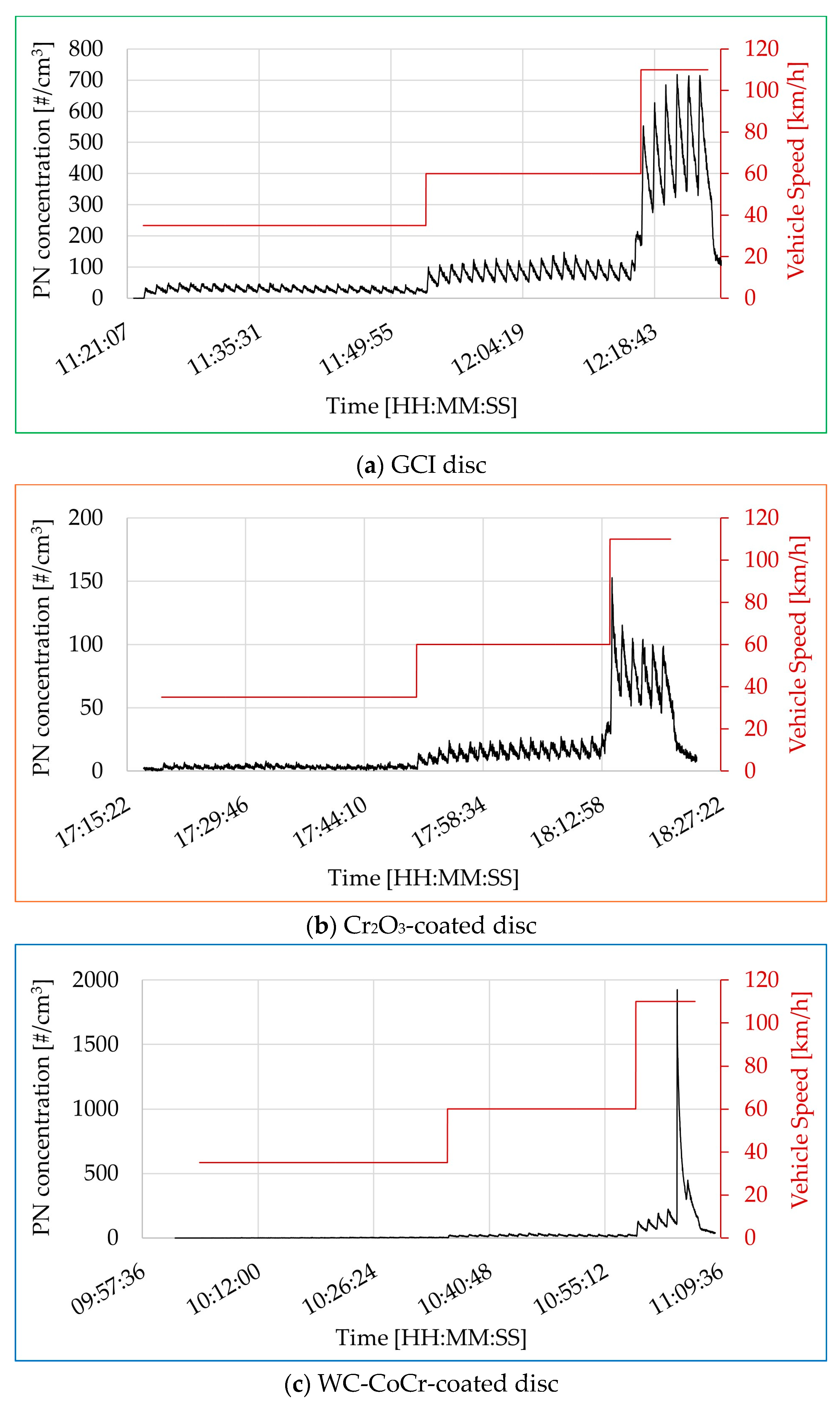
The particle number concentration is measured using the CPC with a sampling frequency of 1 Hz. Figure 2 shows the evolution of the particle number concentration over time of the same friction material tested against all three brake discs (cast iron, Cr2O3-coated, and WC-CoCr-coated). Supplementary Figure S1 presents the same curves by focusing and enlarging the view on PN concentration at each test speed. On these evolution curves, a maximum value (emission peak) results from each loading sequence (characterized by the application of pressure to the surface of the disc). Between two loading sequences, the particle number concentration decreases: a minimum value results from this unloading phase. These curves show that the minimum values measured between the loading sequences increase with the test speed. For example, on the curves of the Cr2O3-coated disc (Figure 2), the minimum values are around 2 #/cm3 for the loading sequences carried out at 35 km/h, around 10 #/cm3 for those at 60 km/h, and around 50 #/cm3 for those at 110 km/h. These curves also show that the number of particles generated during a loading sequence is greater as the sliding speed increases. Indeed, the height of the emission peaks, i.e., the difference between the maximum and minimum value of a loading sequence, is greater with increasing sliding speed. Loading sequences performed at 35 km/h with the Cr2O3-coated disc generate an increase in the particle number concentration of about 6 #/cm3. An increase of about 15 #/cm3 is observed during loading sequences carried out at 60 km/h. And an increase between 50 #/cm3 and 100 #/cm3 is observed during loading sequences carried out at 110 km/h. All these observations are also recorded for the tests carried out with the cast iron disc and the WC-CoCr-coated disc.
The test data presented in Figure 2 were used to calculate the average particle number concentration of each friction pair (Table 6). The average concentrations weighted by the number of loading sequences were also calculated (weighted average concentration). Each weight used for the weighted average calculation corresponds to the proportion of loading sequences performed at each test speed. The average concentrations per speed and the weighted average concentration with the cast iron disc are the highest.
During the test carried out with the WC-CoCr-coated disc, a peak in emissions was measured during the 49th loading sequence of the test, i.e., the 5th loading sequence performed at 110 km/h. This emission peak reached a particle number concentration of 1913 #/cm3 and therefore distorts the average of the particle number concentration calculated at 242 #/cm3 for this test rate, as well as the weighted average of the test calculated at 38 #/cm3 (Table 6). If loading sequences 49 and 50 are not considered in the calculations, then the average particle number concentration at 110 km/h is 115 #/cm3, and the weighted average is 22 #/cm3. Nevertheless, the friction material tested against the WC-CoCr-coated disc generates more particles than that with the Cr2O3-coated disc.
A significant reduction in the weighted averages of the particle number emission of 84% and 64% is thus observed with the Cr2O3-coated disc and the WC-CoCr-coated disc, respectively, compared to the cast iron disc.

3.2. Friction Coefficient

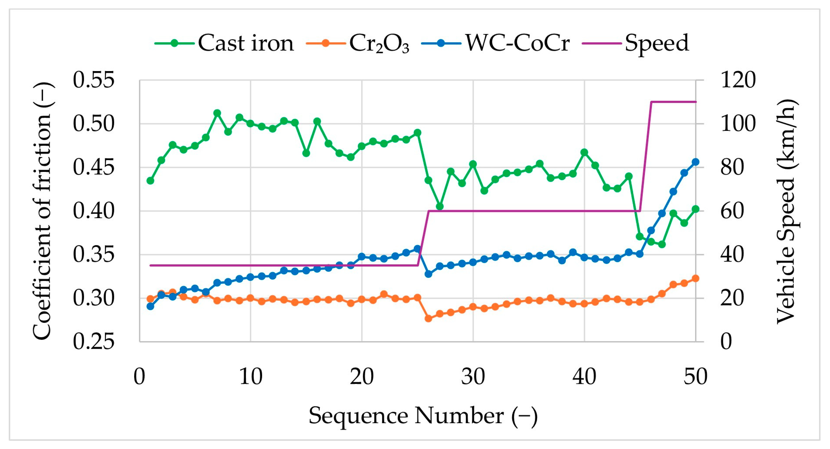
The friction coefficient characterizes the relationship between a normal force applied between two surfaces and the tangential resistance opposing their relative sliding. The friction coefficient between the pin and the disc during each loading sequence was measured using the normal and tangential force sensors. Figure 3 presents the average friction coefficient measured for each loading sequence for each friction pair. Table 7 presents the minimum and maximum values measured during the test and the average values per test speed.
The test speed seems to influence the friction coefficient. Against the cast iron disc, the friction coefficient of the friction pair decreases as the test speed increases. The friction coefficient of the friction pair against the Cr2O3-coated disc is stable during the test, with the average values varying between 0.28 and 0.32 at all test speeds. The friction coefficient of the friction pair against the WC-CoCr-coated disc is less stable than against the Cr2O3-coated disc, especially at 110 km/h, where the average friction coefficient continues to increase from 0.38 in sequence 46 to 0.46 in sequence 50. The friction coefficient against the WC-CoCr-coated disc is higher than against the Cr2O3-coated disc (Figure 3).
The friction coefficient value therefore varies according to the chemical nature of the brake disc: a decrease in the friction coefficient was observed with the use of coated discs compared to cast iron discs. With the Cr2O3-coated disc and WC-CoCr-coated disc, an average decrease of 38% and 32%, respectively, was observed at 35 km/h, and an average decrease of 33% and 21%, respectively, was observed at 60 km/h. On the other hand, at 110 km/h, the friction coefficient with the WC-CoCr-coated disc is on average 10% higher than that with the cast iron disc, while the friction coefficient with the Cr2O3-coated disc remains around 0.31.
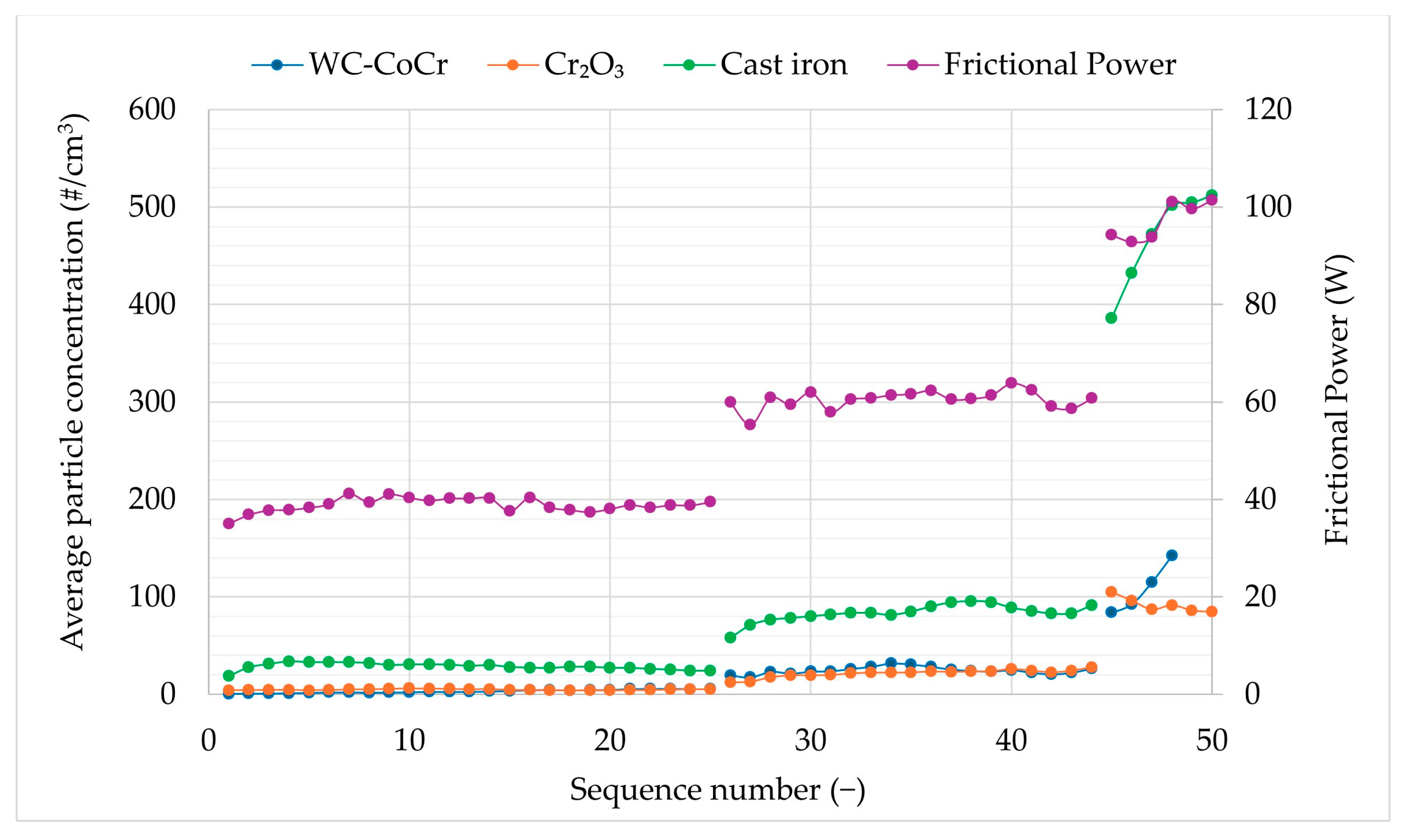
To improve the comparison between the three tests, the particle number concentration data obtained from the three brake discs were compared at the same frictional power to eliminate the effect of the friction coefficient on the results (Figure 4). The decrease in the particle number emission with the coated discs is observed despite the decrease in the friction coefficient observed in Figure 3. With the same frictional power, the average particle number concentration was reduced by 79% with the Cr2O3-coated disc and by 65% with the WC-CoCr-coated disc.

3.3. Particle Size Distribution

The particle size distribution results obtained with the SMPS and APS were aggregated using the Data Merge (TSI) software 1.2 (https://tsi.com/software) to obtain size distributions averaged over the duration of the test and with a measurement range corresponding to the addition of the ranges of the two devices.
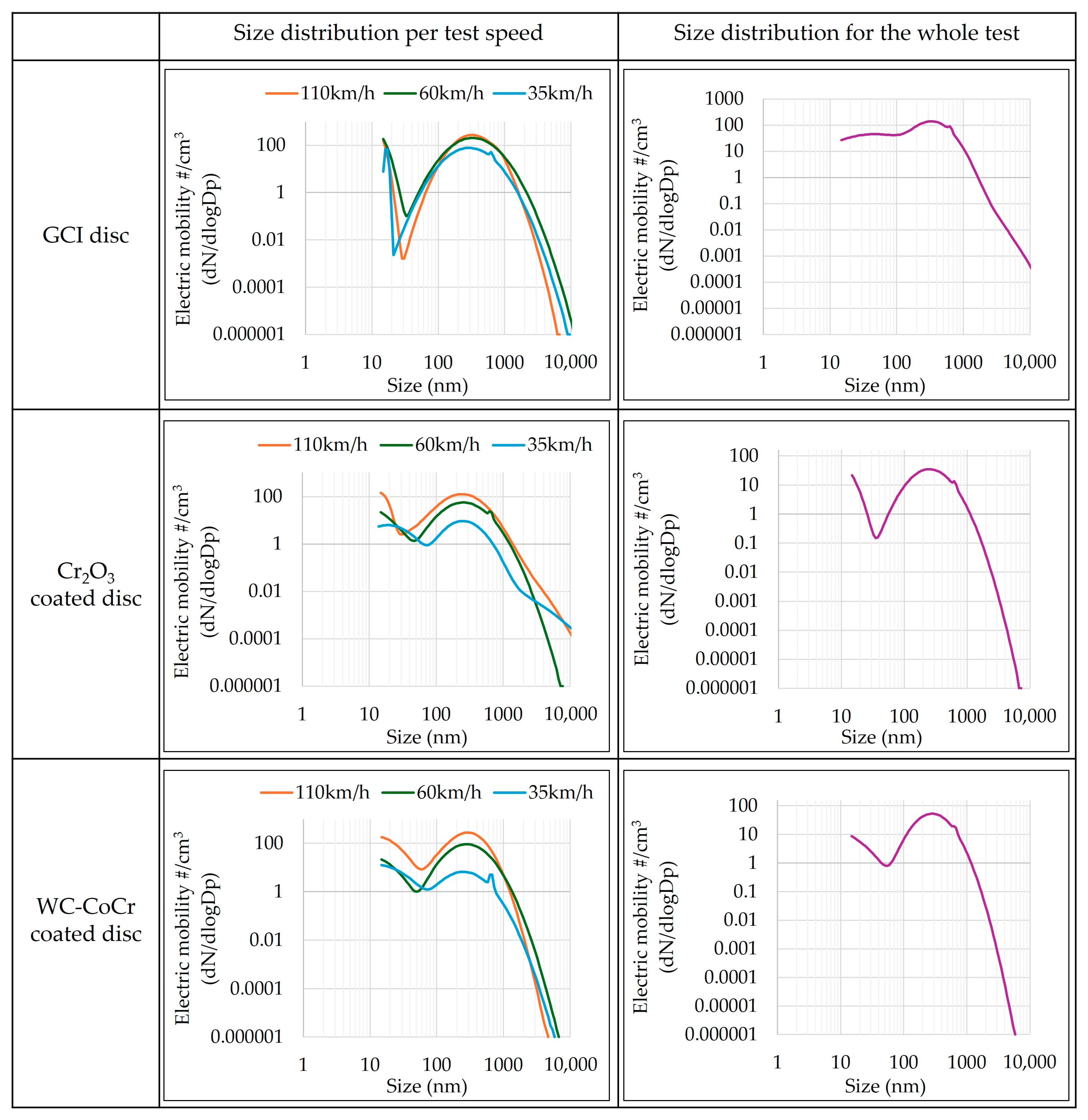
Figure 5 presents the particle size distribution curves of the three friction pairs: against the cast iron disc, against the Cr2O3-coated disc, and against the WC-CoCr-coated disc. In this figure, the particle size distribution for each test speed (35 km/h, 60 km/h, and 110 km/h) is shown, as well as the particle size distribution for the test data set.
The main modes measured with these three brake discs are sub-micron(Table 8). These main modes are slightly lower with coated discs, regardless of the test speed, between 250 nm and 285 nm. Against the cast iron disc, these main modes are between 330 nm and 350 nm. The test carried out with the cast iron disc has a secondary mode in the ultrafine particle spectrum (<100 nm), measured at 15 nm at 35 km/h. The test carried out with the Cr2O3-coated disc also has a secondary mode, measured at 20 nm at 35 km/h. Thus, the particle size distribution modes obtained with the three types of discs show a slight difference. The particles generated during braking appear to be slightly smaller with coated discs, although the presence of a secondary mode below 100 nm is less obvious.

3.4. PM2.5 Emissions

From Equation (1), the emission factor of each friction pair was calculated (Table 9). The emission factor of the three friction pairs is as follows: EFPM2.5 (Cast iron) > EFPM2.5 (WC-CoCr) > EFPM2.5 (Cr2O3), which have values of 9.78 μg/km, 1.58 μg/km, and 0.53 μg/km, respectively.
As a result, the EFPM2.5 emission factor was reduced by 95% with the Cr2O3-coated disc and by 84% with the WC-CoCr-coated disc.

3.5. Chemical Composition of the Generated Particles

PM2.5 collected from the filters was analyzed using both ICP-MS and ICP-OES methods. Table 10 presents the mass concentrations of the chemical elements composing PM2.5 collected on these filters. Depending on the friction material, chemical elements were detected in small quantities, below the limit of quantification defined for each element, resulting in the presence of empty cells in Table 10. Iron is the chemical element most detected on PM2.5 filters, even with both coated discs. The measured iron mass concentrations range from 2.41 μg/m3 to 73.67 μg/m3 depending on the friction pairs. Some of the chemical elements present in brake pads in significant quantities such as magnesium, chromium, zinc, and tin are also found in brake particles [42]. On the other hand, aluminum, which is present in significant quantities in the friction material (Table 2), was detected below the limit of quantification in the cast iron and WC-CoCr-coated disc tests. The presence of 0.70 μg/m3 of chromium in PM2.5 from the Cr2O3-coated disc test is consistent with the coating composition. However, no cobalt was detected in the WC-CoCr-coated disc test, and tungsten could not be analyzed.
Particles were also collected at the source of the particle emission, at the pin-on-disc contact, by a Nanobadge device. TXRF analyses of these particles show the presence of only two chemical elements above the limits of quantification (Table 11). Iron is the main component of the particles generated during braking. Zinc is the second element detected. Chromium, cobalt, and tungsten could not be measured.

3.6. Light Microscopy and Scanning Electron Microscopy

The three brake discs were analyzed before and after the tests using a light microscope. The test pins were analyzed after the tests using a scanning electron microscope coupled with Energy Dispersive X-ray Spectroscopy (EDXS). The used pins were observed in the condition obtained after performing a loading sequence at a speed of 110 km/h. A pin in new condition was also observed.
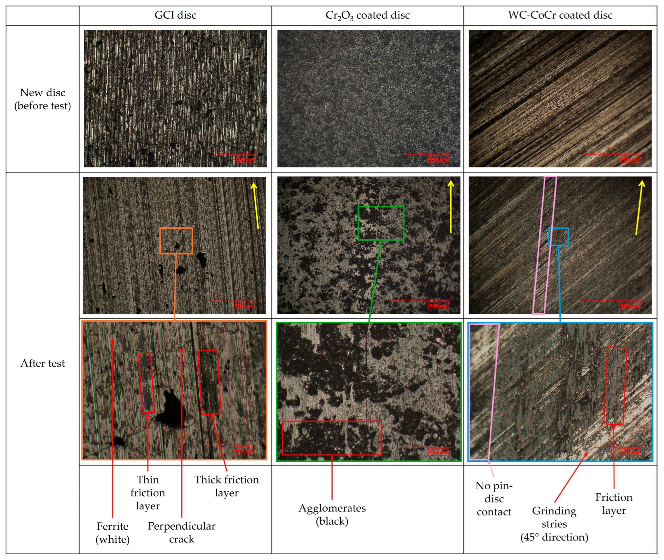
Figure 6 presents light microscope images of the discs before and after the test; the direction of friction during the tests is represented by a yellow arrow. The images of the cast iron disc obtained with the light microscope after testing show microcracks perpendicular to the direction of friction, as well as the presence of black deposits in the direction of friction, whose width is between 10 μm and 50 μm. The color of the deposits is not homogeneous on the surface of the disc. Nevertheless, the presence of deposits on the surface of the cast iron disc is regular over the entire width of the friction track. The images obtained for the two coated discs, before and after the test, are different from those obtained for the cast iron disc. Images of the Cr2O3-coated disc suggest the presence of agglomerates that are black in color and exhibit a wide range of sizes, ranging from 10 μm to more than 200 μm. These agglomerates are evenly distributed on the friction track. Finally, on the surface of the WC-CoCr-coated disc, the presence of machining grooves is observed before testing. After the test, the machining grooves are still partially visible: part of the surface of the WC-CoCr-coated disc has been covered with deposits in the direction of friction. In addition, the contact between the pin and the WC-CoCr-coated disc is not homogeneous, unlike the other two friction pairs. In Figure 6, the areas where the contact between the WC-CoCr-coated disc and the pin did not occur are indicated by purple parallelograms.
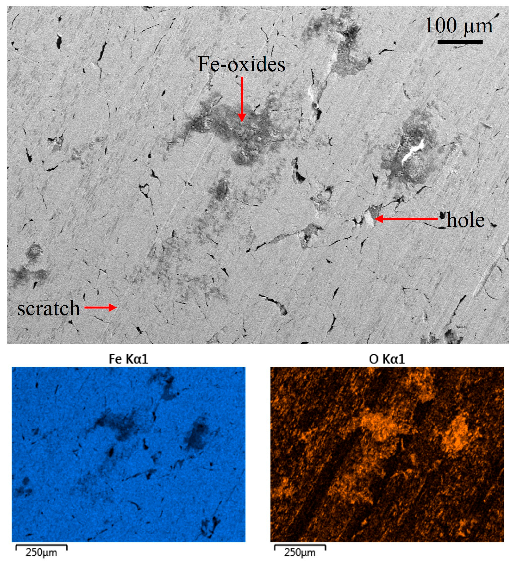
An SEM image and EDXS mappings of the iron and oxygen of the used surface of the cast iron disc are presented in Figure 7. The cast iron disc has several holes and scratches. Grey-colored deposits, composed mainly of iron oxides as shown in the EDXS mappings, have been found on the surface of the disc.
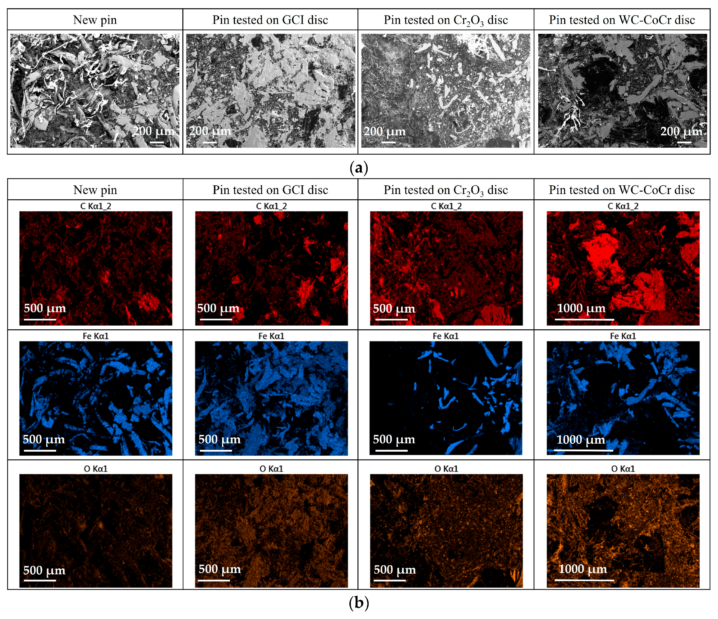
Figure 8 presents SEM images and some EDXS mappings of a new sample of friction material, as well as the three used pins tested against the three types of brake discs. Other EDXS mappings and EDXS spectra are available in Supplementary Figure S2.
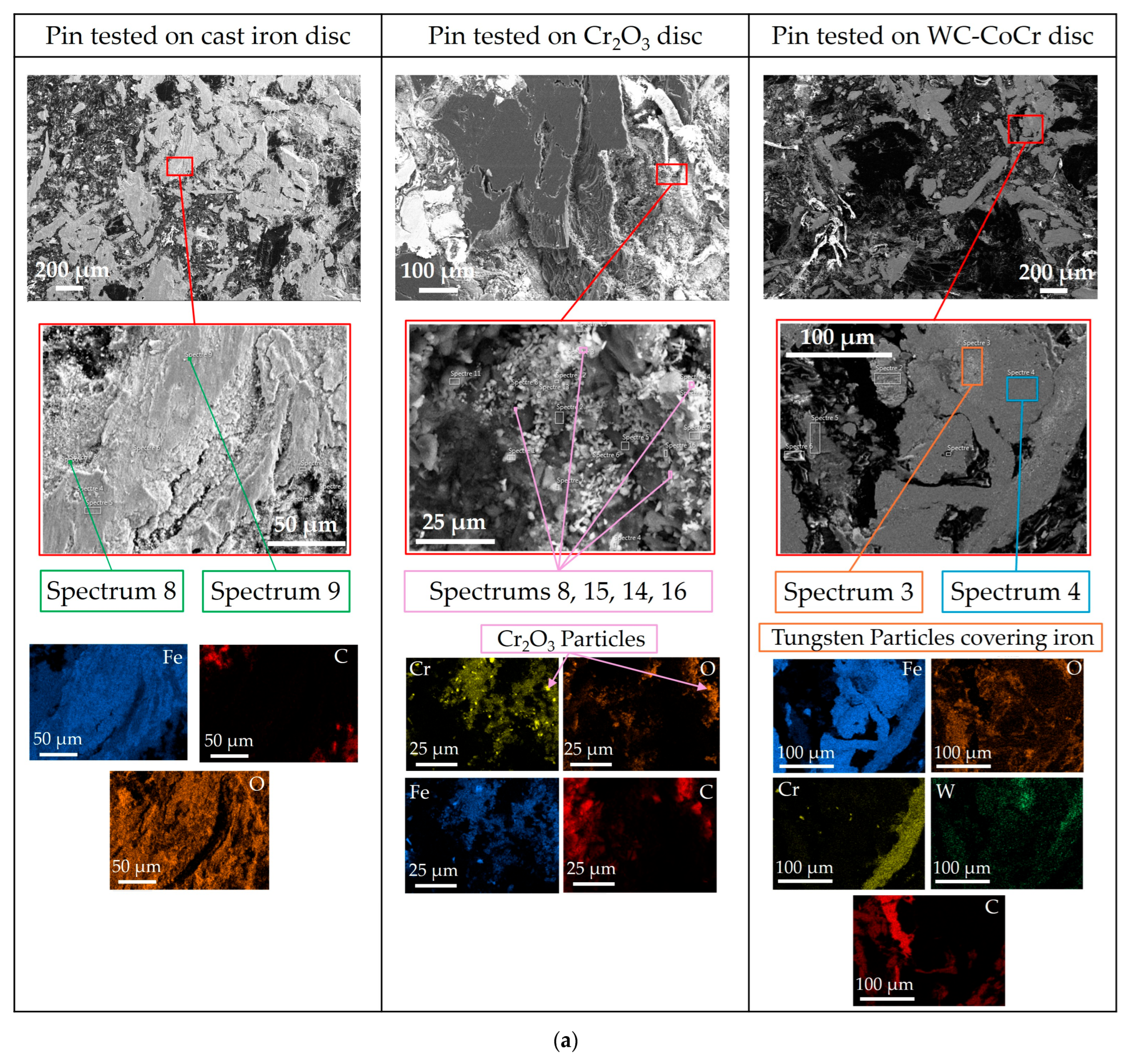
Figure 9 shows magnified views of the images shown in Figure 8. Five chemical elements were of particular interest in the study: carbon, iron, oxygen, chromium, and tungsten.
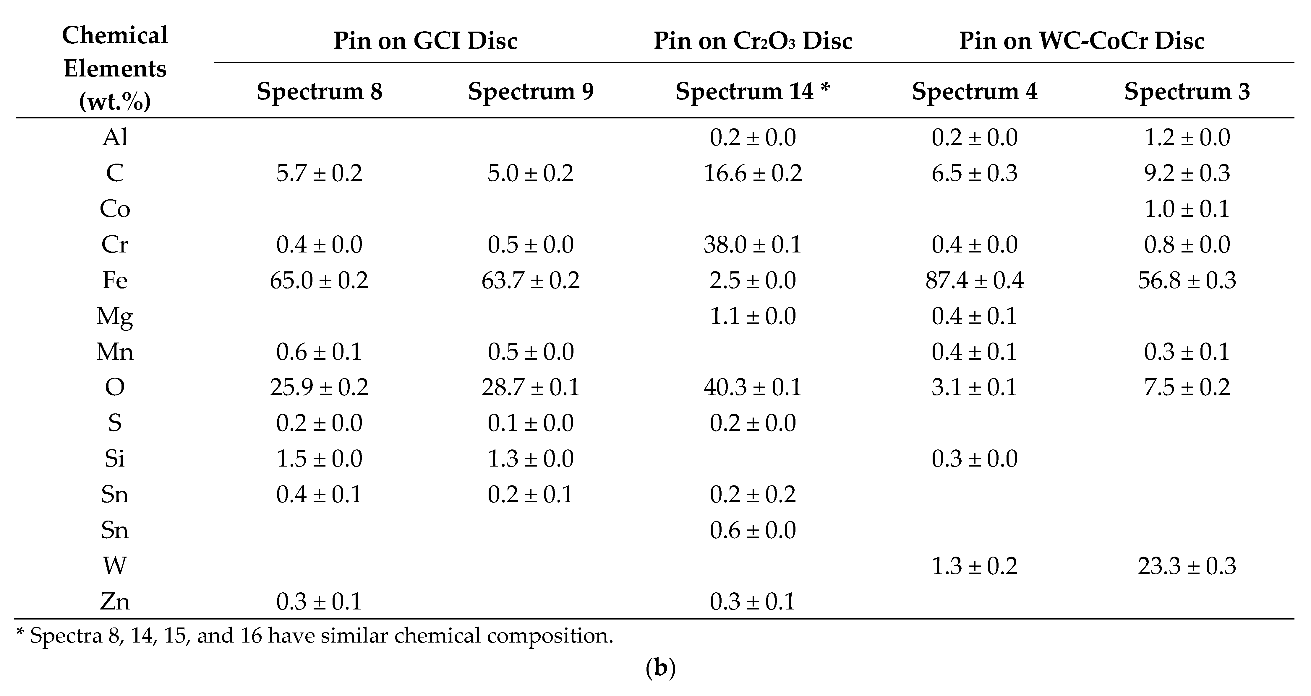
Table 12 presents the weight percentage of the five chemical elements (carbon, iron, oxygen, chromium, and tungsten) measured at the surface of the pins after testing and observed in the SEM images of Figure 8a.
Seven main observations emerge from the SEM images and EDXS mappings presented in Figure 8 and Figure 9, Table 12, and Supplementary Figure S2:
  • On the surface of the new pin, the steel fibers that make up the friction material are not oxidized (Figure 8b).
  • The presence of contact plateaus on the surface of the pin tested against the cast iron disc is identifiable in relation to the pins tested against coated discs (Figure 8b).
  • On the surface of the pin tested against the cast iron disc, the iron and oxygen contents, 25.6 ± 0.1 wt.% and 22.3 ± 0.1 wt.%, respectively, are higher than those observed on the surface of the new pin, 18.3 ± 0.1 wt.% and 14.2 ± 0.1 wt.%, respectively. On the other hand, the carbon content is lower on the surface of the pin tested against the cast iron disc, with a value of 44.9 ± 0.1 wt.%, than on the surface of the new pin, with a value of 57.7 ± 0.1 wt.% (Table 12).
  • On the pins tested against the Cr2O3-coated disc and WC-CoCr-coated disc, the surface contents of iron and oxygen are lower than those of the pin tested against the cast iron disc. On the other hand, the carbon content is higher on the surface of the pins tested against coated discs (Table 12).
  • Elementary mappings of the pin tested against the Cr2O3-coated disc (Figure 9) show the presence of particles composed of oxygen and chromium in the porosities of the pin. In addition, the surface of this pin has the highest chromium content, at 1.8 ± 0.0 wt.% (Table 12). These results suggest the presence of chromium oxide particles (Cr2O3) from the brake disc coating, generated during the loading sequences.
  • Elementary mappings of the pin tested against the WC-CoCr-coated disc show the presence of tungsten particles that cover iron particles (Figure 9). A paper from the literature highlights the same observation, showing that the secondary plateaus of the pin tested against the WC-CoCr-coated disc, composed of tungsten particles, were partially covering the primary plateaus composed of steel fibers [20].
  • The presence of tungsten particles on the surface of the pin suggests that tungsten carbide particles tear off the brake disc coating and then settle on the surface of the steel fibers of the friction material. The WC-CoCr-coated disc therefore shows signs of wear, as does the Cr2O3-coated disc.

4. Discussion

4.1. Wear Mechanisms and Microscopy Analysis

SEM-EDXS analyses performed on the discs and pins in this study made it possible to describe the main tribological mechanisms involved in the pin/disc friction and to understand the differences in particle number and mass emission, particle size distribution, and friction coefficient observed with the three types of discs.
Optical images from Figure 6 have shown different aspects of the three discs after testing. The GCI disc presents some dark deposits whose color may vary. The observed color variations can give an indication of the thickness of these deposits: from experiment; it is assumed that the darker the deposit, the thicker the deposit. The Cr2O3-coated rotor is covered with some deposits looking like agglomerates. The WC-CoCr-coated rotor is covered with unevenly distributed deposits. The appearance of the three brake discs after testing is similar to the appearance of three equivalent discs (cast iron, WC-CoCr, and Cr2C3-NiCr) tested in the literature [20].
SEM images of the cast iron disc in Figure 10 show the presence of holes and scratches on the surface of the disc, characteristic of an abrasion wear mechanism, as observed in the literature [43]. This SEM image also shows the presence of gray deposits on the surface of the disc, formed by tribo-oxidation during friction [20,43].
Our study highlighted similarities between the elementary mappings of iron and oxygen elements of the pin tested against the cast iron disc (Figure 9), suggesting the formation of contact plateaus composed of iron oxides on the surface of the pin [29,44]. Indeed, the cast iron discs would contribute to the formation of wear debris composed of iron, which oxidizes during friction [29]. These iron oxides would participate in the formation of secondary plateaus on the surface of the brake pads [44].
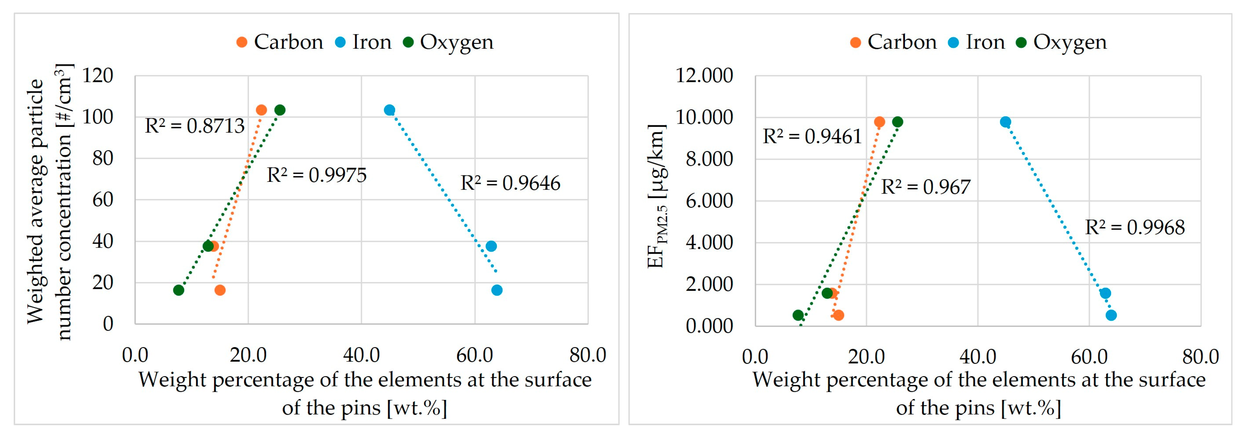
Elementary mappings of the pins tested against the Cr2O3-coated disc and WC-CoCr-coated disc showed lower iron and oxygen contents than those of the pin tested against the cast iron disc (Table 12), as well as different iron and oxygen element mappings (Figure 8b), suggesting that the steel fibers on the surface of these two pins are only slightly oxidized, unlike the steel fibers of the pin tested against the cast iron disc. In the literature, the iron contents of the secondary plateaus observed by SEM-EDXS at the surface of pins tested against coated discs (WC-CoCr and Cr2C3-NiCr), at room temperature and at 300 °C, were also lower than against the cast iron disc. However, the oxygen contents are similar between their three pins [20]. The same trend was observed with a WC-CoCr-coated disc by other authors [21]. These authors mention that with coated discs, the amount of wear debris provided by the discs is not sufficient to form large and well-compacted secondary plateaus. The decrease in oxygen content on the surface of the pins tested against the coated discs observed in our study is therefore probably related to the decrease in iron oxide formation during friction. According to these authors, with coated discs, the secondary plateaus are mainly composed of debris from the friction material. In our study, we have shown that the average particle number concentration is correlated with the iron, oxygen, and carbon concentrations observed at the surface of the used pins (after testing), as well as with the PM2.5 emission factor (Figure 10).
In our study, the elementary mappings of the pin tested against the WC-CoCr-coated disc show the presence of tungsten particles covering the iron particles (Figure 9). In SEM images of a pin tested against the WC-CoCr-coated disc, an author from the literature also observed that the secondary plateaus, composed of tungsten particles, partially covered the primary plateaus, mainly composed of steel fibers [20]. The presence of tungsten particles on the surface of the pin suggests that tungsten carbide particles are torn off from the brake disc coating and then built up on the steel fibers of the friction material. Detachments of tungsten carbide particles from the coating, forming holes on the disc surface, were also observed in another study [23].

4.2. Particle Emissions per Number and Mass
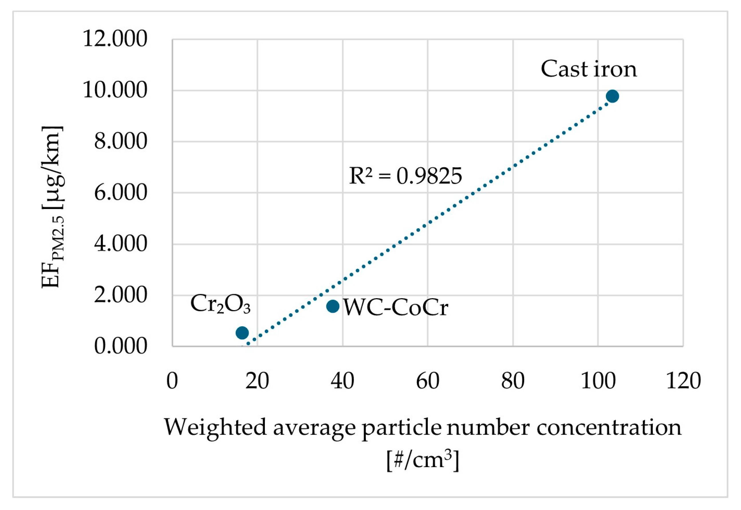
This study shows that both coated discs, one coated with chromium oxide and the other with tungsten–chromium–cobalt carbide, significantly reduce the brake particle number emissions by 84% and 64%, respectively, and the corresponding particle mass emissions by 95% and 84%, respectively. Some correlations have been observed with the particle number and are described below.
The test results show a correlation between the emission factor and the average particle number concentration (Figure 11): the particle mass emission increases with the particle number emission.
Figure 11. Weighted average particle number concentration vs. EFPM2.5.
Environments 12 00341 g011
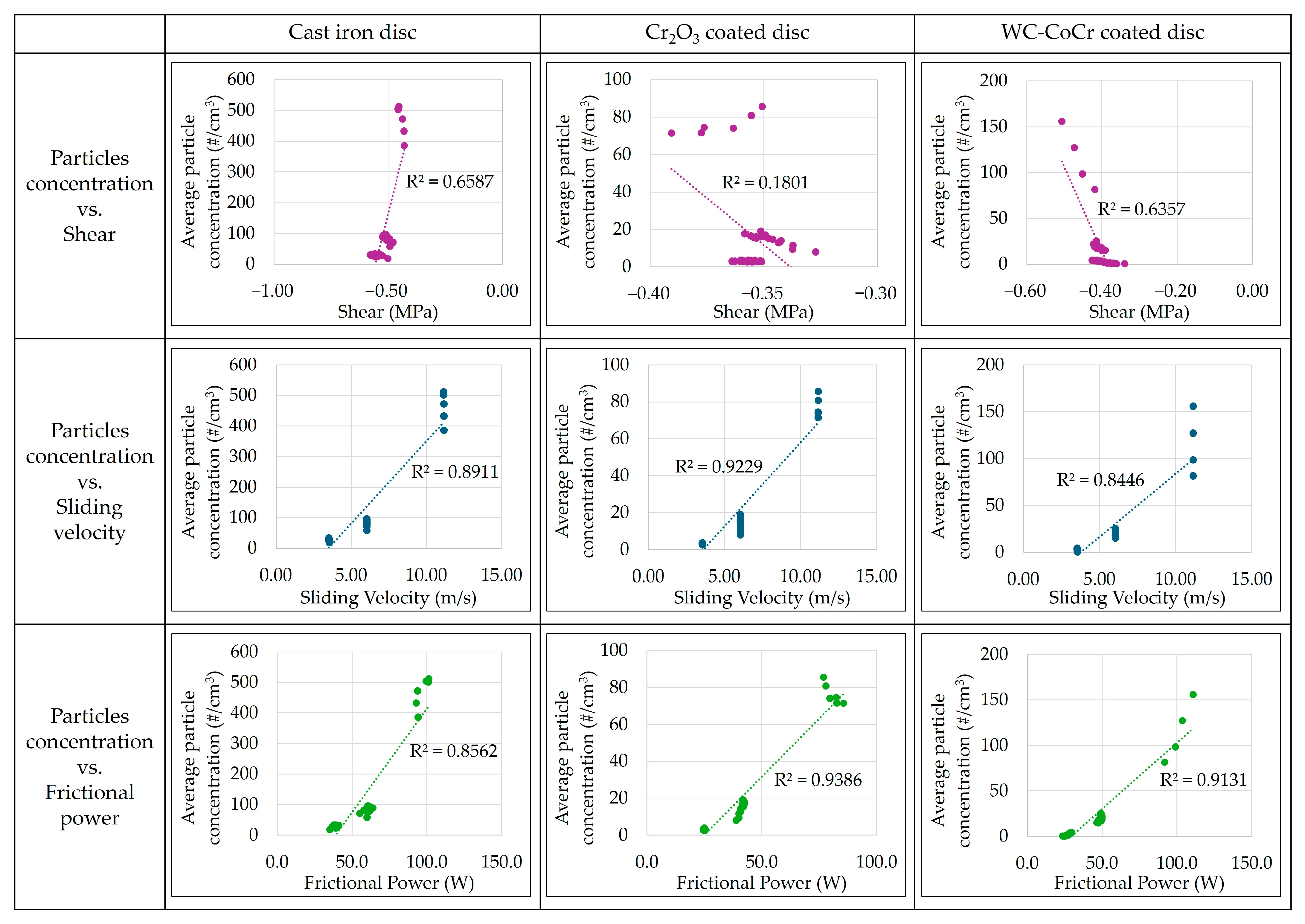
Figure 12. Effect of shear, sliding velocity, and frictional power on particle number concentration.
Environments 12 00341 g012
The frictional power generated during the 50 loading sequences of each test was calculated using Equation (2). The frictional power (in watts) is a function of μ, the friction coefficient (unitless); FN, the normal force (N); and v, the sliding speed (m/s). The friction coefficient μ is a function of the normal force FN (N) and the tangential force FT (N).
P = µ F N v     ;   µ = a b s F T F N
Figure 12 shows the average particle number concentration of each loading sequence as a function of shear, or sliding speed, or frictional power. The test with the WC-CoCr-coated disc was plotted without sequences 49 and 50. A correlation between the average particle number concentration and the sliding speed was observed with the three discs: as the sliding speed increases, the average particle number concentration increases. This result agrees with some data in the literature [25,45,46]. However, the results presented here highlight that these correlations are also observed with coated disc surfaces. As a result, these correlations seem to be independent of the type of disc surface and could be explained by the increased surface in contact per unit time due to an increased sliding speed, which consequently causes higher particle emissions. A correlation between the average particle number concentration and the frictional power was also observed with the three discs: as the frictional power increased, the average particle number concentration increased. The correlation between frictional power and particulate emissions while testing on a pin-on-disc bench was also observed by other authors [25,27,45].
On the other hand, no correlation between the mean shear stress values (and the friction coefficient) and the average particle number concentration appears.
Several reasons have been identified for reducing brake wear particle emissions, such as the hardness, porosity, roughness, and oxidation of the discs.
The hardness of the coated discs (1100 HV0.3) is much higher than that of the cast iron disc, by about 235 HV10 [47]; the abrasion wear of the coated discs by the brake pads is therefore more difficult.
The porosity of the Cr2O3 coating is about 5%, and that of the WC-CoCr coating is less than 1%, while the porosity of the cast iron disc is zero. A porous material has closed cavities (at depth) that become open porosities as it wears out. In this study, the use of porous disc coatings could thus promote the transfer of material from the pin to the disc as the brake disc wears out. The light microscope images of both used coated discs (Figure 6) suggest that a transfer of wear debris from the friction material to the cavities of the disc coatings has occurred. SEM-EDXS analyses will therefore have to be performed on the coated discs in order to determine the composition of these material deposits observed on the surface of these discs, as well as in the cavities of the coatings. The presence of friction material debris in the cavities of the WC-CoCr and Cr2C3-NiCr coatings was observed in the literature [23]. A negative wear of the WC-CoCr-coated disc was measured in the literature, showing that a transfer of material from the pin to the disc had occurred [9].
The roughness and relative load length ratio (Rmr) of the discs (ratio between the number of valleys and the number of peaks) could also impact the wear behavior of friction pairs. The higher these two parameters, the smaller the contact surface between the pin and the disc, thus increasing the contact pressure. In this case, abrasive wear prevails over adhesive wear [34].
Oxidation of the disc: the chemical reactivity (oxidation) forming a layer of oxides, in particular iron oxides, at the interface between the pin and the disc is different depending on the chemical nature of the disc: the iron and oxygen contents on the surface of the three pins suggest that the chemical reactivity is different depending on the friction pairs: LS/GCI > LS/WC-CoCr > LS/Cr2O3. The decrease in the oxygen content on the surface of the pins tested against the coated discs is probably related to the decrease in the formation of iron oxides during friction. In addition, the cast iron disc would contribute to the formation of wear debris composed of iron, which oxidizes during friction [34]. These iron oxides participate in the formation of secondary plateaus on the surface of the brake pads [44]. On the other hand, the authors mention that with coated discs, the amount of wear debris provided by the discs is not sufficient to form large, well-compacted secondary plateaus. With coated discs, these plateaus are mainly composed of debris from the friction material.

4.3. Peak Emission with WC-CoCr-Coated Disc

There are three reasons why the peak emission measured at 110 km/h with the WC-CoCr-coated disc can be found. First, the roughness of the coated disc may not be suitable for this type of tribology test, carried out on a pin-on-disc bench with a 5 mm diameter pin. Indeed, the presence of machining grooves after testing suggests that the roughness of the disc is too high for such a small pin, or that the friction material is mechanically too weak to wear the disc. It would be interesting to carry out a test on a dynamometer test, in accordance with the Euro 7 standard, to see if machining grooves are still observable after the test by using a larger friction material surface than the pin, thus generating higher mechanical and thermal stresses than on a pin-on-disc bench. Secondly, there can be a tearing off of material (friction material) due to poor compatibility between the friction material and the coated disc. This is because the tungsten carbide grains in the disc coating are harder than some brake pad components, which could make it easier to pull them off. If this case were verified, then the friction material would be mechanically too weak for this type of brake disc. Finally, the peak in emissions could also be due to the deterioration of the coating itself. The CoCr matrix can wear out, and tungsten carbide particles are automatically released when the matrix wears out.

4.4. Chemical Composition of the Particles

The study showed that the particles collected on the PM2.5 filter were mainly composed of iron. A study carried out with cast iron discs and a disc coated by the Laser Cladding process also mentioned this observation [43].
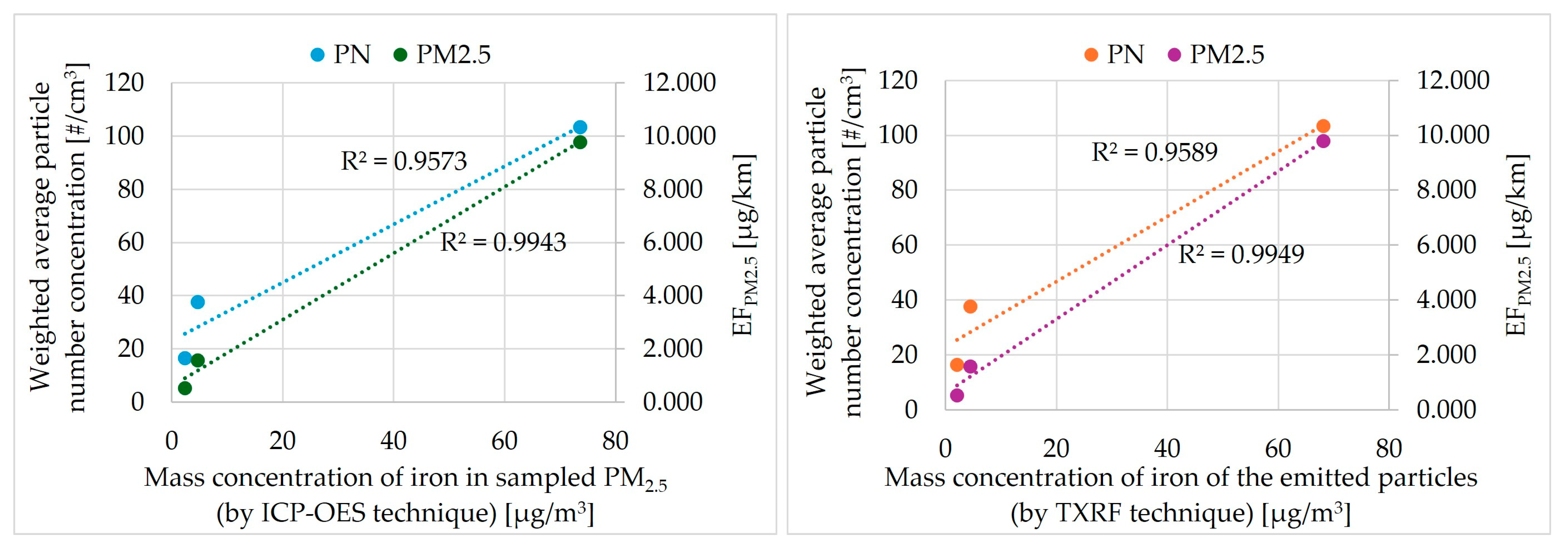
In our study, a correlation was observed between the average particle number concentration, the emission factor EFPM2.5, and the iron mass concentration of PM2.5 collected on the filters (Figure 13, left). Thus, the higher the iron content in PM2.5, the higher the emissions in number and mass. The number and mass of emitted particles were also observed to be correlated with the iron content of particles collected at the source of the pin-on-disc contact, ranging in size from 10 nm to 4.5 μm (Figure 13, right).

4.5. Friction Coefficient

In this study, the friction coefficient of the friction material tested against the Cr2O3-coated disc is stable throughout the test, but lower than the friction coefficient of the friction material tested against the cast iron disc. The results of our study carried out on a pin-on-disc bench corroborate the results of [19], which compared two friction pairs tested on a dynamometer according to the SAE J2430 procedure. Its results show that regardless of the section of the SAE J2430 test, the friction coefficient of the friction material tested against a Cr2O3-2%TiO2-coated disc is lower than that of the friction material tested against a cast iron disc.
In this study, the friction coefficient of the tested friction material against the WC-CoCr-coated disc is lower than the friction coefficient of the tested friction material against the cast iron disc when the contact pressure is 1.2 MPa and the sliding speeds are 3.6 m/s (equivalent vehicle speed of 35 km/h) or 6.1 m/s (equivalent vehicle speed of 60 km/h). However, at 11.2 m/s (equivalent vehicle speed of 110 km/h), the friction coefficient with the WC-CoCr-coated disc is higher than with the cast iron disc. The latter result, obtained for a sliding speed of 11.2 m/s and a contact pressure of 1.2 MPa, corroborates the observations found in the literature [20,21]. A low-steel friction material was tested against a WC-CoCr-coated disc at a contact pressure of 0.65 MPa and a sliding speed of 5 m/s [21]. The authors measured a higher friction coefficient with the WC-CoCr-coated disc than with the cast iron disc. A slight increase in the friction coefficient with their WC-CoCr-coated disc tested against a low-steel material at a contact pressure of 1 MPa and a sliding speed of 1.57 m/s was observed in another study [20]. The increase in the friction coefficient observed with their WC-CoCr-coated discs is due to the increase in abrasive mechanisms in the presence of hard particles (tungsten carbides) on the disc surface [20,21]. Furthermore, the decrease in the adhesive part is also due to the decrease in the formation of iron oxide particles formed by tribo-oxidation and transferred to the surface of the pin to form the secondary plateaus. Unlike our study, both of those studies were carried out at constant sliding speed and contact pressure.
To understand the decrease in the friction coefficient observed with the use of coated discs at 35 km/h and 60 km/h, quantification of the carbon content on the surface of the pins using SEM-EDX could help us. Indeed, the decrease in the friction coefficient with coated discs could be due to an increase in the carbon content on the surface of the pins during the tests. In the field of friction materials, carbon is known to have lubricant properties, thus helping to reduce the friction coefficient between the brake pad and the disc. The increase in the carbon content on the surface of the pins could be due to a spreading of the raw materials containing carbon (present in the friction material), the carbonization of organic matter during friction, or the reduction in the formation of secondary plateaus composed of iron oxides. To understand this phenomenon, chemical analyses must be carried out after each phase of the test: at 35 km/h, at 60 km/h, and at 110 km/h, to quantify the evolution of the carbon content during the test. This idea comes from the observations made with SEM-EDX on the pins after the test (Table 12) and from the correlations observed between the emission of particles (number and mass) and the carbon content on the surface of the pins after the test (Figure 10). The emission of particles decreases when the carbon content on the surface of the pins (after the test) increases. However, these correlations were made from observations made on pins whose final state results from the last loading sequence between the pin and the disc, carried out at 110 km/h. Furthermore, the instability of the friction coefficient observed during the 110 km/h phase with the WC-CoCr-coated disc does not allow this hypothesis to be validated since the friction coefficient of the WC-CoCr-coated disc exceeds that of the cast iron disc at the end of the test (at 110 km/h).

4.6. Particle Size Distribution

The main modes obtained with the coated brake discs are slightly lower, between 250 nm and 285 nm, compared to the main modes obtained with the cast iron disc, between 330 nm and 350 nm. These results are in line with the literature. A study showed particle size distribution modes close to ours, around 200 nm, for three types of tested discs (grey cast iron, HVOF WC-CoCr, and Laser Cladding Fe-based) [21].
Two reasons have been identified that may justify this slight change in the particle size distribution in our study: the reduction in iron particle emission, and the pin/disc contact temperature.
The iron element is the main chemical tracer found in the brake particle emissions measured in this study, regardless of the type of disc (cast iron disc, WC-CoCr-coated disc and Cr2O3-coated disc) (Table 11). Thus, to verify the first hypothesis, it would be necessary to perform TEM (Transmission Electron Microscopy) analyses to determine the morphology and size of the iron particles collected on the PM2.5 filters [48,49].
The literature shows that the number of ultrafine particles increases as the brake disc temperature increases [50,51,52,53]. To verify the second hypothesis, defining the thermal conductivity of each brake disc could be an interesting avenue to follow because it would allow us to evaluate the ability of the discs to dissipate the heat generated during braking. Installing a device on the pin-on-disc bench to measure the disc temperature would thus help to measure the temperature differences between the discs.

5. Conclusions

As brake disc/brake pad friction pairs are a significant source of air pollution, the study of the composition of brake discs is an interesting avenue for reducing particle emissions into the environment. The objectives of this study were to investigate the influence of the composition of three brake discs (cast iron disc, Cr2O3-coated disc, and WC-CoCr-coated disc) tested against a single friction material of the low-steel family on the emission of particulate matter in number and mass, and on particle size, and to understand some wear mechanisms involved in particle emissions.
The Cr2O3-coated disc and the WC-CoCr-coated disc reduced the brake particle number emissions by 64% and 84%, respectively, compared to the uncoated cast iron disc, as well as the particle mass emission by 95% and 84%, respectively. The main modes of particle size distribution obtained with the coated brake discs are slightly lower, between 250 nm and 285 nm, compared to the main modes obtained with the cast iron disc, between 330 nm and 350 nm.
Several correlations were observed between the emission of particles in number or mass and the test parameters, the chemical composition of the surface of the friction materials, or the chemical composition of the airborne particles. A correlation was established between the particle number concentration and
-
The EFPM2.5 emission factor;
-
The mass concentration of iron in the particles generated;
-
The concentration of iron, oxygen, and carbon on the surface of the used pins;
-
Frictional power and sliding speed.
A correlation was also established between the emission factors and
-
The mass concentration of iron in the particles generated;
-
The concentration of iron, oxygen, and carbon on the surface of the used pins.
Analyses carried out by light microscopy and SEM-EDXS show that the tribological mechanisms are different depending on the nature of the brake disc. Morphological and chemical differences were observed on the surface of the pins and of the three types of brake discs. The chemical composition of the surface of the pins after testing is different depending on the disc used. The carbon content is higher on the pins tested against the coated discs, compared to that tested against the cast iron disc. On the other hand, the iron and oxygen contents are lower on the pins tested against the coated discs than with the cast iron disc. It therefore seems that the presence of a layer of iron oxides (formation of large and well-compacted secondary plateaus) on the surface of the friction pair, partially made of the cast iron material of the brake disc, seems to be at the origin of the high emissivity of the friction pair (cast iron disc/low-steel friction material). So, the wear mechanisms involved with GCI discs are tribo-oxidation and abrasion, which generate high brake emissions. Even though the microscopic analyses showed the proof of disc coating wear, it seems that the wear debris goes into the cavities of the coated discs (due to their high porosity) and the pins. Furthermore, the amount of wear debris is too low to form large and well-compacted secondary plateaus mainly made of iron oxides.

6. Perspectives

Additional SEM-EDXS analyses of the two coated discs will be required to validate all hypotheses. The study of the effect of the hardness, porosity, and roughness of the coated discs on the emissions is also an interesting avenue.
Comparison tests on a dynamometer are envisaged, according to the GTR No.24 procedure mentioned by the Euro 7 emission standard, both to verify the effect of the coated discs on the reduction in particulate emissions and to verify whether the machining grooves observed on the WC-CoCr-coated disc are still present after the test. At the end of these tests, the coated discs can be analyzed using SEM-EDXS to better understand the tribological mechanisms behind particle emission.
Among the avenues for further study, the instrumentation of devices to measure temperature during the tests would make it possible to discriminate against thermal effects, as the thermal conductivity of the three discs is different.
Finally, it would be interesting to analyze the surface condition of the pins and discs after each test phase (35 km/h, 60 km/h, and 110 km/h) to determine both the iron, oxygen, and carbon contents on the surface of the pins and to better understand the effect of speed on particle emissions and the friction coefficient (as the friction coefficient is rather low with coated discs). An alternative way to increase the friction coefficient would be to create new friction materials, for example, by decreasing the content of carbon-containing raw materials, since the content of carbon observed at the surface of the pins tested against the coated discs is high (as the carbon is considered as a lubricant).
The use of coated discs is recommended to reduce the PM emission factor of friction pairs (brake pad/brake disc), especially for internal combustion engine vehicles that are not equipped with regenerative braking.

Supplementary Materials

The following supporting information can be downloaded at https://www.mdpi.com/article/10.3390/environments12100341/s1, Figure S1: Enlarged evolution of the particle number concentration of the three friction pairs; Figure S2: Chromium and Tungsten EDXS mapping from a new pin and the three pins after testing.

Author Contributions

Conceptualization, M.H., Y.-M.C., M.M. and C.B.; methodology, M.H., Y.-M.C., M.M. and C.B.; validation, M.H. and Y.-M.C.; formal analysis, M.H.; investigation, M.H. and L.M.; resources, M.H., Y.-M.C., M.M., L.M. and C.B.; data curation, M.H.; writing—original draft preparation, M.H.; writing—review and editing, M.H., Y.-M.C., M.M. and C.B.; visualization, M.H.; supervision, Y.-M.C., M.M. and C.B.; project administration, M.M.; funding acquisition, Y.-M.C., M.M. and C.B. All authors have read and agreed to the published version of the manuscript.

Funding

This research was supported by the French Agency for Ecological Transition (ADEME), grant number [2166D0017], and by the National Association of Research and Technology (ANRT), grant number [2022/0336].

Data Availability Statement

The original contributions presented in this study are included in the article/Supplementary Materials. Further inquiries can be directed to the corresponding author(s).

Acknowledgments

The authors acknowledge their institutions for making this project possible. The authors also acknowledge their funders, the French Agency for Ecological Transition (ADEME) funding AQACIA project D-brake [2166D0017], the National Association of Research and Technology [2022/0336], and the French Minister for Ecology (MIV32 Program). The authors would like to thank David Cazé (Cetim, Senlis) for helping in the realization of the pin-on-disc tests.

Conflicts of Interest

Author Marie Hoff was employed by the company MAT Friction Noyon SAS. The remaining authors declare that the research was conducted in the absence of any commercial or financial relationships that could be construed as a potential conflict of interest.

References

  1. Xing, Y.-F.; Xu, Y.-H.; Shi, M.-H.; Lian, Y.-X. The impact of PM2.5 on the human respiratory system. J. Thorac. Dis. 2016, 8, 69–74. [Google Scholar] [CrossRef]
  2. Geiser, M.; Rothen-Rutishauser, B.; Kapp, N.; Schurch, S.; Kreyling, W.; Schulz, H.; Semmler, M.; Im Hof, V.; Heyder, J.; Gehr, P. Ultrafine particles cross cellular membranes by nonphagocytic mechanisms in lungs and in cultured cells. Environ. Health Perspect 2005, 113, 1555–1560. [Google Scholar] [CrossRef] [PubMed]
  3. Oberdorster, G.; Oberdorster, E.; Oberdorster, J. Nanotoxicology: An emerging discipline evolving from studies of ultrafine particles. Environ. Health Perspect 2005, 113, 823–839. [Google Scholar] [CrossRef] [PubMed]
  4. European Environment Agency. Air Quality in Europe 2022; European Environment Agency: Copenhagen, Denmark, 2022. [Google Scholar]
  5. Milojević, S.; Džunić, D.; Marić, D.; Skrúcaný, T.; Mitrović, S.; Pešić, R. Tribological Assessment of Aluminum Cylinder Material for Piston Compressors in Trucks and Buses Brake Systems. Teh. Vjesn.-Tech. Gaz. 2021, 28, 1268–1276. [Google Scholar] [CrossRef]
  6. Timmers, V.R.J.H.; Achten, P.A.J. Non-exhaust PM emissions from electric vehicles. Atmos. Environ. 2016, 134, 10–17. [Google Scholar] [CrossRef]
  7. Gagnepain, L. Emissions des Véhicules Routiers—Les Particules Hors Échappement; La librairie (ADEME): Angers, France, 2022. [Google Scholar]
  8. The European Parliament and the Council of the European Union. Regulation (EU) 2024/1257 of the European Parliament and of the Council of 24 April 2024; European Union: Brussels, Belgium, 2024. [Google Scholar]
  9. Wahlström, J.; Lyu, Y.; Matjeka, V.; Söderberg, A. A pin-on-disc tribometer study of disc brake contact pairs with respect to wear and airborne particle emissions. Wear 2017, 384–385, 124–130. [Google Scholar] [CrossRef]
  10. Perricone, G.; Matějka, V.; Alemani, M.; Valota, G.; Bonfanti, A.; Ciotti, A.; Olofsson, U.; Söderberg, A.; Wahlström, J.; Nosko, O.; et al. A concept for reducing PM 10 emissions for car brakes by 50%. Wear 2018, 396–397, 135–145. [Google Scholar] [CrossRef]
  11. Cai, R.; Zhang, J.; Nie, X.; Tjong, J.; Matthews, D.T.A. Wear mechanism evolution on brake discs for reduced wear and particulate emissions. Wear 2020, 452–453, 203283. [Google Scholar] [CrossRef]
  12. Dizdar, S.; Lyu, Y.; Lampa, C.; Olofsson, U. Grey Cast Iron Brake Discs Laser Cladded with Nickel-Tungsten Carbide—Friction, Wear and Airborne Wear Particle Emission. Atmosphere 2020, 11, 621. [Google Scholar] [CrossRef]
  13. Seo, H.; Joo, B.; Park, J.; Kim, Y.C.; Lee, J.J.; Jang, H. Effect of disc material on particulate matter emissions during high-temperature braking. Tribol. Int. 2021, 154, 106713. [Google Scholar] [CrossRef]
  14. Hesse, D.; Hamatschek, C.; Augsburg, K.; Weigelt, T.; Prahst, A.; Gramstat, S. Testing of Alternative Disc Brakes and Friction Materials Regarding Brake Wear Particle Emissions and Temperature Behavior. Atmosphere 2021, 12, 436. [Google Scholar] [CrossRef]
  15. Babu, P.S.; Sen, D.; Jyothirmayi, A.; Krishna, L.R.; Rao, D.S. Influence of microstructure on the wear and corrosion behavior of detonation sprayed Cr2O3-Al2O3 and plasma sprayed Cr2O3 coatings. Ceram. Int. 2018, 44, 2351–2357. [Google Scholar] [CrossRef]
  16. Cellard, A.; Garnier, V.; Fantozzi, G.; Baret, G.; Fort, P. Wear resistance of chromium oxide nanostructured coatings. Ceram. Int. 2009, 35, 913–916. [Google Scholar] [CrossRef]
  17. Rastegar, F.; Craft, A.E. Piston ring coatings for high horsepower diesel engines. Surf. Coat. Technol. 1993, 61, 36–42. [Google Scholar] [CrossRef]
  18. Güney, B.; Mutlu, I. Tribological Properties of Brake Discs Coated with Cr2O3–40% TiO2 by Plasma Spraying. Surf. Rev. Lett. 2019, 26, 1950075. [Google Scholar] [CrossRef]
  19. Mutlu, I.; Güney, B.; Erkurt, I. Investigation of the effect of Cr2O3-2% TiO2 coating on braking performance. Int. J. Automot. Eng. Technol. 2020, 9, 29–41. [Google Scholar] [CrossRef]
  20. Federici, M.; Menapace, C.; Moscatelli, A.; Gialanella, S.; Straffelini, G. Pin-on-disc study of a friction material dry sliding against HVOF coated discs at room temperature and 300 °C. Tribol. Int. 2017, 115, 89–99. [Google Scholar] [CrossRef]
  21. Lyu, Y.; Sinha, A.; Olofsson, U.; Gialanella, S.; Wahlström, J. Characterization of ultrafine particles from hardfacing coated brake rotors. Friction 2022, 11, 125–140. [Google Scholar] [CrossRef]
  22. Hoff, M.; Chen, Y.-M.; Meunier, L.; Bressot, C.; Morgeneyer, M. Effect of Friction Material on Vehicle Brake Particle Emissions. Atmosphere 2025, 16, 1075. [Google Scholar] [CrossRef]
  23. Wahlstrom, J.; Soderberg, A.; Olander, L.; Jansson, A.; Olofsson, U. A pin-on-disc simulation of airborne wear particles from discbrakes. Wear 2010, 268, 763–769. [Google Scholar] [CrossRef]
  24. Sanders, P.G.; Xu, N.; Dalka, T.M.; Maricq, M.M. Airborne brake wear debris: Size distributions, composition, and a comparison of dynamometer and vehicle tests. Environ. Sci. Technol. 2003, 37, 4060–4069. [Google Scholar] [CrossRef]
  25. Candeo, S.; Leonardi, M.; Gialanella, S.; Straffelini, S. Influence of contact pressure and velocity on the brake behaviour and particulate matter emissions. Wear 2023, 514–515, 204579. [Google Scholar] [CrossRef]
  26. Dridi, B.; Hjelm, R.; Lattanzi, L.; Awe, S.; Pagels, J.; Wahlström, J.; Lyu, Y. On the influence of carbides in laser-cladded coating on friction, wear, and airborne particle emissions of disc brakes. Wear 2025, 576–577, 206107. [Google Scholar] [CrossRef]
  27. Philippe, F. Measure and Characterization of Braking Particles Emitted from Cars on a Pin-in-Disc Bench. Ph.D. Thesis, Université de Technologie de Compiègne, Compiègne, France, 2021. Available online: https://theses.fr/2021COMP2615 (accessed on 16 September 2025).
  28. Philippe, F.; Xiang, M.; Bressot, C.; Chen, Y.; Guingand, F.; Charles, P.; Loigerot, J.; Morgeneyer, M. Relevance of pin-on-disc and inertia dynamometer bench experiments for braking emission studies. J. Phys. Conf. Ser. 2019, 1323, 012025. [Google Scholar] [CrossRef]
  29. Philippe, F.; Morgeneyer, M.; Xiang, M.; Manokaran, M.; Berthelot, B.; Chen, Y.-m.; Charles, P.; Guingand, F.; Bressot, C. Representativeness of airborne brake wear emission for the automotive industry: A review. Proc. Inst. Mech. Eng. Part D J. Automob. Eng. 2021, 235, 2651–2666. [Google Scholar] [CrossRef]
  30. Motellier, S.; Lhaute, K.; Guiot, A.; Golanski, L.; Geoffroy, C.; Tardif, F. Direct quantification of airborne nanoparticles composition by TXRF after collection on filters. J. Phys. Conf. Ser. 2011, 304, 012009. [Google Scholar] [CrossRef]
  31. NF-EN-14385; Stationary Source Emissions—Determination of the Total Emission of As, Cd, Cr, Co, Cu, Mn, Ni, Pb, Sb, TI and V. Association Française de Normalisation: La Plaine Saint-Denis, France, 2024.
  32. NF-EN-17294-2; Water Quality—Application of Inductively Coupled Plasma Mass Spectrometry (ICP-MS)—Part 2: Determination of Selected Elements Including Uranium Isotopes. Association Française de Normalisation: La Plaine Saint-Denis, France, 2023.
  33. NF-EN-ISO-11885; Water quality—Determination of Selected Elements by Inductively Coupled Plasma Optical Emission Spectrometry (ICP-OES). Association Française de Normalisation: La Plaine Saint-Denis, France, 2009.
  34. Federici, M.; Menapace, C.; Moscatelli, A.; Gialanella, S.; Straffelini, G. Effect of roughness on the wear behavior of HVOF coatings dry sliding against a friction material. Wear 2016, 368–369, 326–334. [Google Scholar] [CrossRef]
  35. Abbasi, S.; Wahlström, J.; Olander, L.; Larsson, C.; Olofsson, U.; Sellgren, U. A study of airborne wear particles generated from organic railway brake pads and brake discs. Wear 2011, 273, 93–99. [Google Scholar] [CrossRef]
  36. Federici, M.; Perricone, G.; Gialanella, S.; Straffelini, G. Sliding Behaviour of Friction Material Against Cermet Coatings: Pin-on-Disc Study of the Running-in Stage. Tribol. Lett. 2018, 66, 53. [Google Scholar] [CrossRef]
  37. Lyu, Y.; Wahlström, J.; Tu, M.; Olofsson, U. A Friction, Wear and Emission Tribometer Study of Non-Asbestos Organic Pins Sliding Against AlSiC MMC Discs. Tribol. Ind. 2018, 40, 274–282. [Google Scholar] [CrossRef]
  38. Metinoz, I.; Matejka, V.; Alemani, M.; Wahlström, J.; Perricone, G. Could pin-on-disc tribometers be used to study the friction/wear performance of disc brake materials? In Proceedings of the Eurobrake 2016, Milan, Italy, 13–15 June 2016. [Google Scholar]
  39. Philippe, F.; Xiang, M.; Morgeneyer, M.; Chen, Y.-M.; Charles, P.; Guingand, F.; Bressot, C. Emission rate assessment of airborne brake particles by characterization of the pad and disc surfaces from a pin-on-disc tribometer. Toxicol. Res. Appl. 2020, 4, 2397847320977782. [Google Scholar] [CrossRef]
  40. Wahlström, J.; Söderberg, A.; Olander, L.; Olofsson, U.; Jansson, A. Airborne wear particles from passenger car disc brakes: A comparison of measurements from field tests, a disc brake assembly test stand, and a pin-on-disc machine. Proc. Inst. Mech. Eng. Part J J. Eng. Tribol. 2009, 224, 179–188. [Google Scholar] [CrossRef]
  41. UNECE. UN GTR No.24—Laboratory Measurement of Brake Emissions for Light-Duty Vehicles (17/07/2023); UNECE: Geneva, Switzerland, 2023. [Google Scholar]
  42. Neukirchen, C.; Saraji-Bozorgzad, M.R.; Mader, M.; Mudan, A.P.; Czasch, P.; Becker, J.; Di Bucchianico, S.; Trapp, C.; Zimmermann, R.; Adam, T. Comprehensive elemental and physical characterization of vehicle brake wear emissions from two different brake pads following the Global Technical Regulation methodology. J. Hazard. Mater. 2025, 482, 136609. [Google Scholar] [CrossRef]
  43. Lyu, Y.; Varriale, F.; Malmborg, V.; Ek, M.; Pagels, J.; Wahlström, J. Tribology and airborne particle emissions from grey cast iron and WC reinforced laser cladded brake discs. Wear 2024, 556–557, 205512. [Google Scholar] [CrossRef]
  44. Eriksson, M.; Jacobson, S. Tribological surfaces of organic brake pads. Tribol. Int. 2000, 33, 817–827. [Google Scholar] [CrossRef]
  45. Alemani, M.; Wahlström, J.; Olofsson, U. On the influence of car brake system parameters on particulate matter emissions. Wear 2018, 396–397, 67–74. [Google Scholar] [CrossRef]
  46. Hagino, H.; Oyama, M.; Sasaki, S. Airborne brake wear particle emission due to braking and accelerating. Wear 2015, 334–335, 44–48. [Google Scholar] [CrossRef]
  47. Candeo, S.; Varriale, F.; Nogueira, A.P.; Gialanella, S.; Straffelini, G. Performance of a cast-iron and WC Co-free iron-based coated disc under mild and severe brake conditions. Wear 2024, 548–549, 205369. [Google Scholar] [CrossRef]
  48. Xiang, M.; Morgeneyer, M.; Aguerre-Chariol, O.; Lefebvre, C.; Philippe, F.; Meunier, L.; Bressot, C. A Quantitative Method for Characterizing of Structures’ Debris Release. Eng 2025, 6, 157. [Google Scholar] [CrossRef]
  49. Xiang, M.; Morgeneyer, M.; Philippe, F.; Bressot, C. Airborne nanoparticle (Nanoaerosol) sampling efficiency analysis based on filtration on TEM grid. J. Phys. Conf. Ser. 2019, 1323, 012002. [Google Scholar] [CrossRef]
  50. Nosko, O.; Alemani, M.; Olofsson, U. Temperature effect on emission of airborne wear particles from car brakes. In Proceedings of the EuroBrake 2015, Dresden, Germany, 4–6 May 2015. [Google Scholar]
  51. Nosko, O.; Olofsson, U. Effective density of airborne wear particles from car brake materials. J. Aerosol Sci. 2017, 107, 94–106. [Google Scholar] [CrossRef]
  52. Kukutschová, J.; Roubíček, V.; Malachová, K.; Pavlíčková, Z.; Holuša, R.; Kubačková, J.; Mička, V.; MacCrimmon, D.; Filip, P. Wear mechanism in automotive brake materials, wear debris and its potential environmental impact. Wear 2009, 267, 807–817. [Google Scholar] [CrossRef]
  53. Nosko, O.; Vanhanen, J.; Olofsson, U. Emission of 1.3–10 nm airborne particles from brake materials. Aerosol Sci. Technol. 2016, 51, 91–96. [Google Scholar] [CrossRef]
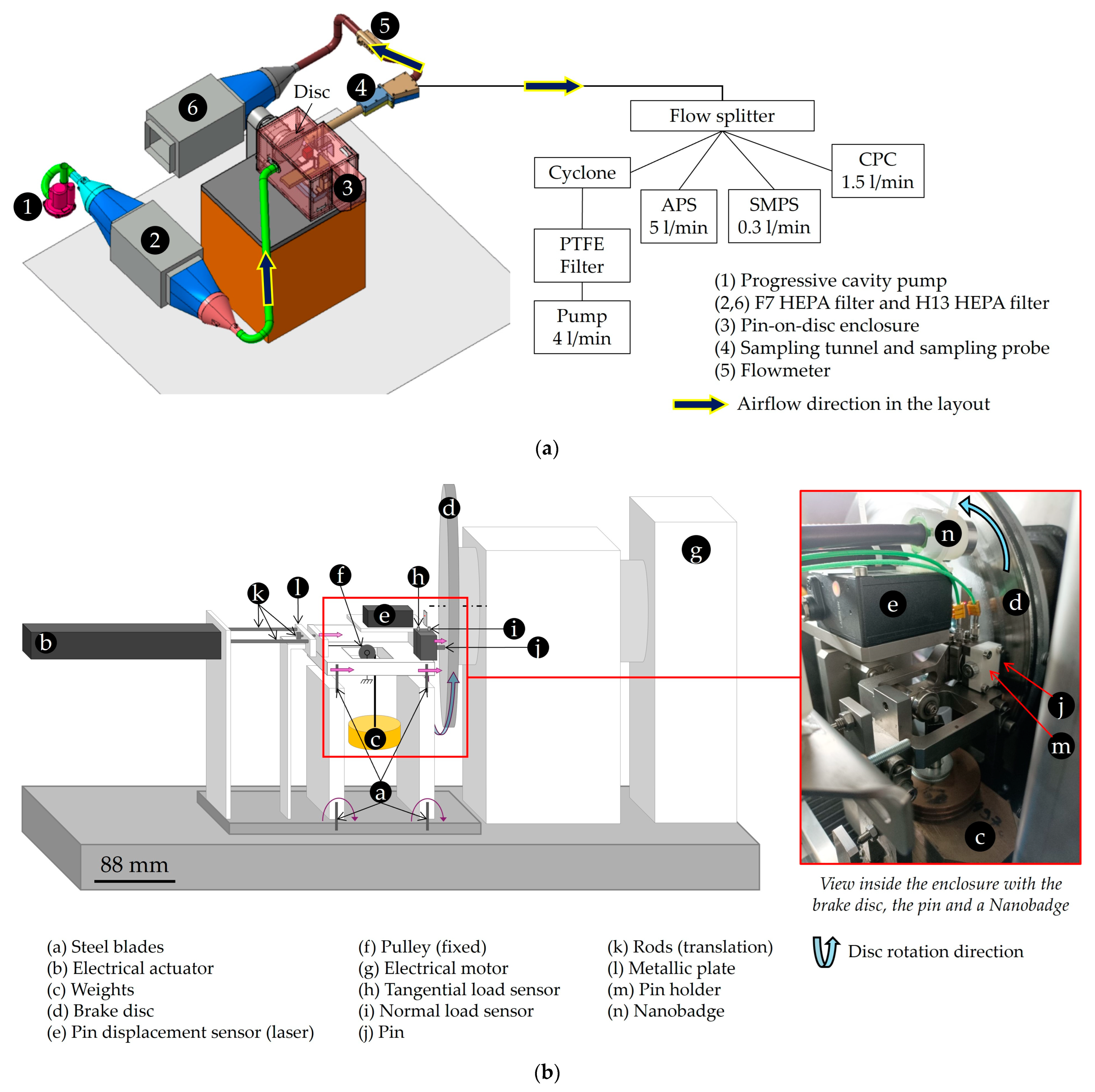
Figure 1. Scheme of the pin-on-disc bench: (a) the set-up for brake particle measurements; (b) inside the enclosure (mechanical part).
Environments 12 00341 g001
Figure 2. Evolution of the particle number concentration during testing with (a) GCI disc, (b) Cr2O3-coated disc, and (c) WC-CoCr-coated disc.
Environments 12 00341 g002
Figure 3. Average friction coefficient per test sequence.
Environments 12 00341 g003
Figure 4. Comparison of the particle number concentration at identical frictional power.
Environments 12 00341 g004
Figure 5. Particle size distribution of the 3 friction pairs, with cast iron disc, Cr2O3-coated disc, and WC-CoCr-coated disc.
Environments 12 00341 g005
Figure 6. Optical microscopies of the discs before and after testing; the friction direction is represented by a yellow arrow.
Environments 12 00341 g006
Figure 7. SEM image and EDXS mappings of the cast iron disc after testing.
Environments 12 00341 g007
Figure 8. Friction material pins observed before and after testing: (a) SEM images; (b) EDXS mappings.
Environments 12 00341 g008
Figure 9. Pins observed in detail after testing: (a) SEM images and EDXS mappings; (b) chemical composition of the spectra.
Environments 12 00341 g009aEnvironments 12 00341 g009b
Figure 10. Correlation between the chemical composition at the surface of the pins after testing and (left) the average particle number concentration and (right) the PM2.5 emission factor.
Environments 12 00341 g010
Figure 13. Average particle number concentration and PM2.5 emission factor as a function of (left) iron mass concentration in sampled PM2.5 emissions and (right) iron mass concentration of particles emitted at the pin-on-disc contact.
Environments 12 00341 g013
Table 1. Characteristics of the particle measurement and collection devices.
InstrumentCPCSMPSAPSFilterNanobadge
ModelTSI 3775TSI 3082TSI 3321
Measurable particle diameter range, nm4–300014–700520–20,000<250010–4500
Aerosol inlet flow rate, L/min1.50.35.04.01.0
Table 2. Chemical composition of the friction materials and grey cast iron disc.
Elementary Composition [wt.%]
ElementLSGCI DiscElementLSGCI Disc
Al9.62≤0.015Ni 0.047
C 3.37P 0.037
Ca0.34 S4.340.065
Cr1.190.18Si0.502.06
Cu0.020.32Sn3.840.048
Fe34.28RestTi 0.013
Mg37.43≤0.010Zn7.68
Mn 0.72Zr0.01
Mo0.090.016Other0.66
Table 3. Characteristics of the three types of disc.
Disc TypeSurface CompositionSurface
Porosity
HardnessRoughness (Ra)Relative Load Length Ratio (Rmr)
GCI 93% Fe, 3.37% C, 2.06% Si, main elements0%
Cr2O3>99.6% of Cr2O35%1100 HV0.30.528 µm≈80%
WC-CoCr86% WC, 10% Co, 4% Cr<1%1100 HV0.30.133 µm≈50%
Table 4. Test procedure for the pin-on-disc bench.
Test PhasesCycle NameNumber of
Sequences
Loading
Sequences’
Duration (s)
Break Between Each Loading
Sequence (s)
Contact
Pressure (MPa)
Sliding
Velocity (m/s)
Vehicle Speed (km/h)
1Bedding5010601.28.280
2Emission2510601.23.635
3Emission1910601.26.160
4Emission610601.211.2110
Table 5. Vehicle and pin-on-disc parameters.
Vehicle ParametersPin-on-Disc Parameters
Test Inertia (WLTP) (kg.m2)Rolling
Radius
(mm)
Effective
Radius
(mm)
Brake Piston Diameter (mm)Brake Pad Surface (mm2)Test
Radius
(mm)
Pin
Diameter (mm)
55.68295108.5544510108.55
Table 6. Average particle concentration per vehicle speed; the values calculated without sequences 49 and 50 are shown in parentheses.
Cast IronCr2O3WC-CoCr
Average particle concentration at 35 km/h, #/cm32932
Average particle concentration at 60 km/h, #/cm3861520
Average particle concentration at 110 km/h, #/cm346877242 (115)
Weighted average particle concentration *, #/cm31031638 (22)
* Calculated with a weight of 50% at 35 km/h, 38% at 60 km/h, and 12% at 110 km/h.
Table 7. Minimum, maximum, and average friction coefficient values.
Cast IronCr2O3WC-CoCr
Min value0.360.280.29
Max value0.510.320.46
Average 35 km/h0.480.300.33
Average 60 km/h0.440.290.34
Average 110 km/h0.380.310.42
Table 8. Particle size distribution modes.
Cast IronCr2O3WC-CoCr
First modeWhole test330 nm250 nm285 nm
35 km/h330 nm265 nm265 nm
60 km/h330 nm250 nm285 nm
110 km/h350 nm250 nm285 nm
Second modeWhole test50 nm<14 nm (suspected)<14 nm (suspected)
35 km/h15 nm20 nm<14 nm (suspected)
60 km/h<14 nm (suspected)<14 nm (suspected)<14 nm (suspected)
110 km/h<14 nm (suspected)<14 nm (suspected)<14 nm (suspected)
Table 9. Emission factor of the 3 friction pairs.
Cast IronCr2O3WC-CoCr
Filter mass [mg]0.0370.0020.006
Total distance [km]53.02253.12653.128
qm/qp ratio14.01913.99913.944
EFPM2.5 [μg/km]9.780.531.58
Table 10. Chemical composition of PM2.5 particles (by ICP techniques).
Chemical Elements (µg/m3)
BNaMgAlTiCrFeZnSn
Cast iron 0.36 0.5273.670.600.50
Cr2O30.750.040.160.300.080.702.410.590.14
WC-CoCr 0.29 0.214.680.790.30
Table 11. Main chemical composition of generated particles (Nanobadge/TXRF).
Chemical Elements (µg/m3)
FeZn
Cast iron68.060.38
Cr2O32.140.53
WC-CoCr4.530.40
Table 12. Weight percentage (wt.%) of elements at the surface of the pins presented in Figure 8b.
New PinPin Tested
on Cast Iron Disc
Pin Tested on Cr2O3-Coated DiscPin Tested on WC-CoCr-Coated Disc
Carbon57.744.963.962.9
Iron18.325.67.712.9
Oxygen14.222.315.013.8
Chrome0.00.61.81.0
Tungsten0.00.00.01.5
Disclaimer/Publisher’s Note: The statements, opinions and data contained in all publications are solely those of the individual author(s) and contributor(s) and not of MDPI and/or the editor(s). MDPI and/or the editor(s) disclaim responsibility for any injury to people or property resulting from any ideas, methods, instructions or products referred to in the content.