Next Article in Journal
Geotectonic Controls on CO2 Formation and Distribution Processes in the Brazilian Pre-Salt Basins
Next Article in Special Issue
Formation of the Yamal Crater in Northern West Siberia: Evidence from Geochemistry
Previous Article in Journal
Preservation of Cultural Heritage and Resources Threatened by Climate Change
Previous Article in Special Issue
Methane in Gas Shows from Boreholes in Epigenetic Permafrost of Siberian Arctic
 
 
Comment published on 2 September 2019, see Geosciences 2019, 9(9), 384.
Article

Understanding the Permafrost–Hydrate System and Associated Methane Releases in the East Siberian Arctic Shelf

1
Institute of Natural Resources, National Tomsk Research Polytechnic University, 30 Prospect Lenina, Tomsk 634050, Russia
2
International Arctic Research Center, University Alaska Fairbanks, Akasofu Building, Fairbanks, AK 99775-7320, USA
3
Pacific Oceanological Institute, Russian Academy of Science, 41 Baltiiskaya Street, Vladivostok 690022, Russia
4
Moscow Institute of Physics and Technology, 9 Institutskiy per., Dolgoprudny, Moscow Region 141701, Russia
5
Science and Education Center, Northern (Arctic) Federal University, Naberezhnaya Severnoy Dvini, 17, Arkhangelsk 163002, Russia
6
Skolkovo Institute of Science and Technology (Skoltech), 3, Nobel st., Innovation Center Skolkovo, Moscow 121205, Russia
*
Author to whom correspondence should be addressed.
Geosciences 2019, 9(6), 251; https://doi.org/10.3390/geosciences9060251
Submission received: 4 April 2019 / Revised: 14 May 2019 / Accepted: 3 June 2019 / Published: 5 June 2019
(This article belongs to the Special Issue Gas and Gas Hydrate in Permafrost)

Abstract

:
This paper summarizes current understanding of the processes that determine the dynamics of the subsea permafrost–hydrate system existing in the largest, shallowest shelf in the Arctic Ocean; the East Siberian Arctic Shelf (ESAS). We review key environmental factors and mechanisms that determine formation, current dynamics, and thermal state of subsea permafrost, mechanisms of its destabilization, and rates of its thawing; a full section of this paper is devoted to this topic. Another important question regards the possible existence of permafrost-related hydrates at shallow ground depth and in the shallow shelf environment. We review the history of and earlier insights about the topic followed by an extensive review of experimental work to establish the physics of shallow Arctic hydrates. We also provide a principal (simplified) scheme explaining the normal and altered dynamics of the permafrost–hydrate system as glacial–interglacial climate epochs alternate. We also review specific features of methane releases determined by the current state of the subsea-permafrost system and possible future dynamics. This review presents methane results obtained in the ESAS during two periods: 1994–2000 and 2003–2017. A final section is devoted to discussing future work that is required to achieve an improved understanding of the subject.

1. Introduction

The Arctic is warming dramatically, with potentially catastrophic impacts on climate through rapid mobilization of the labile reservoirs of carbon sequestered in permafrost [1]. The top candidate to move substantial amounts of carbon from land and ocean to atmosphere on decadal–century timescales is thawing permafrost in the Arctic [2,3,4]. One possible feedback is release of previously produced methane (CH4) preserved within seabed deposits, such as natural gas fields and coal beds, and collapse of the CH4 hydrates underlying the Arctic seabed [5,6]. The lack of understanding of this process creates some of the largest uncertainties in climate research related to cryosphere–climate–carbon couplings [7,8,9].
Significant reserves of CH4 are held in the Arctic seabed [10], but the release of CH4 to the overlying ocean and, subsequently, to the atmosphere has been believed to be restricted by impermeable subsea permafrost, which has sealed the upper sediment layers for thousands of years [11]. In the regions where permafrost exists, hydrate-bearing sediment deposits can reach a thickness of 400 to 800 m [12,13]. Shallow hydrate deposits are predicted to occupy ~57% (1.25 × 10⁶ km2) of the East Siberian Arctic Shelf (ESAS) seabed [14]. It has been suggested that destabilization of shelf Arctic hydrates could lead to large-scale enhancement of aqueous CH4, but this process was hypothesized to be negligible on a decadal–century time scale [15].Consequently, the continental shelf of the Arctic Ocean (AO) has not been considered as a possible source of CH4 to the atmosphere until very recently [16,17,18].
The key area of the AO for atmospheric venting of CH4 is the East Siberian Arctic Shelf (ESAS). The ESAS covers greater than two million square kilometers (equal to the areas of Germany, France, Great Britain, Italy, and Japan combined). This vast yet shallow region has recently been shown to be a significant modern source of atmospheric CH4, contributing annually no less than terrestrial Arctic ecosystems [19,20]; but unlike terrestrial ecosystems, the ESAS emits CH4 year-round due to its partial openness during the winter when terrestrial ecosystems are dormant [21]. Emissions are determined by and dependent on the current thermal state of the subsea permafrost and environmental factors controlling permafrost dynamics [21,22]. Releases could potentially increase by 3–5 orders of magnitude, considering the sheer amount of CH4 preserved within the shallow ESAS seabed deposits and the documented thawing rates of subsea permafrost reported recently [22]. The purpose of this paper is to introduce the ESAS permafrost–hydrates system, which is largely unfamiliar to scientists, by highlighting the specific processes that determine and control its dynamics.

2. Major Components of the ESAS Permafrost–Hydrate System

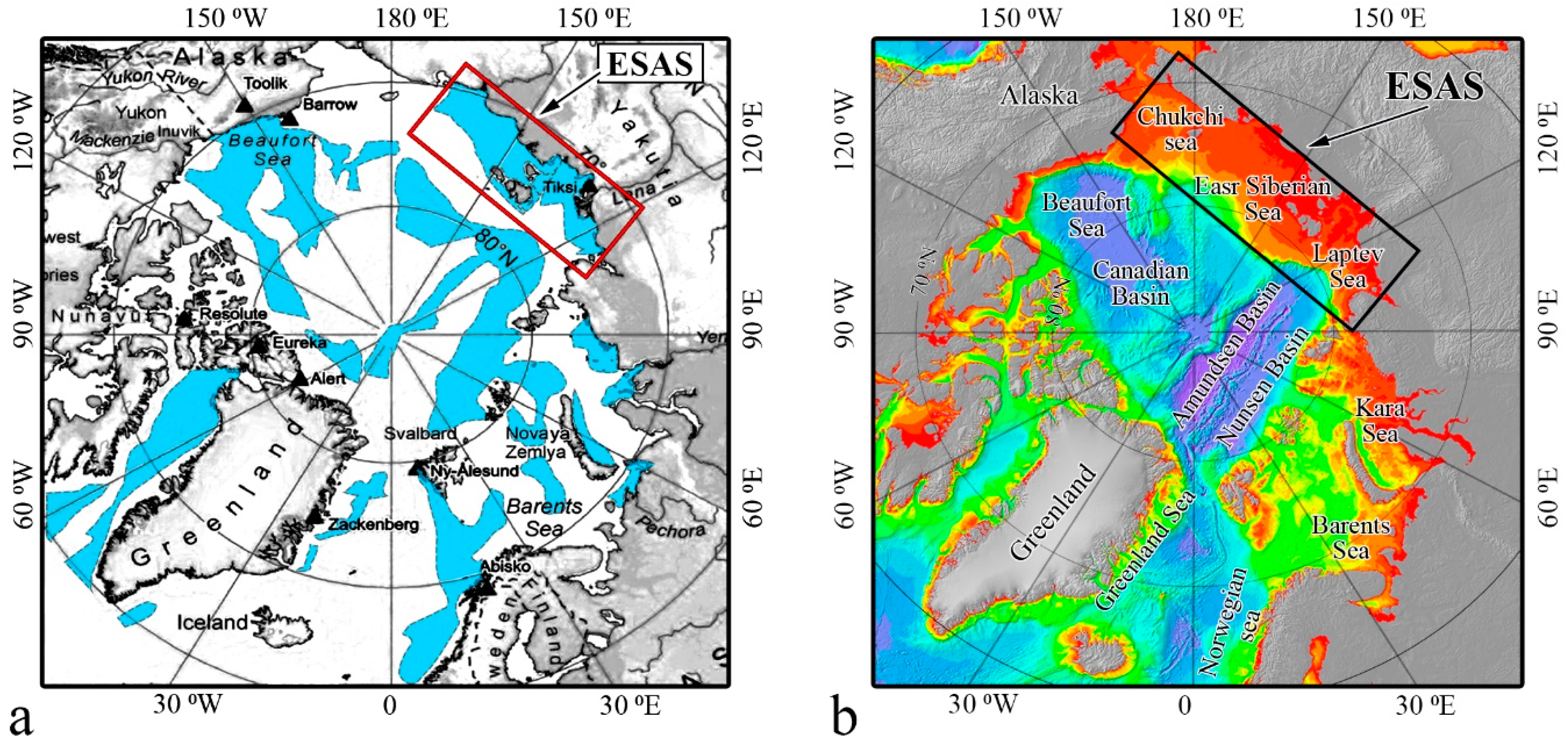
2.1. Specific Features of the ESAS Environment

The ESAS is the most extensive (2.1 × 10⁶ km2) continental shelf in the World Ocean (WO); the ESAS is composed of the Laptev Sea, the East Siberian Sea, and the Russian part of the Chukchi Sea. Because of its shallowness (mean depth is ~50 m, Figure 1a) and location, the ESAS has a unique climatological history; due to sea level variations caused by glaciation in cold climate epochs or by glacier melt during warm epochs, the entire area of the ESAS is periodically subjected to dry (terrestrial) or to submerged (marine) conditions [23].
The ESAS near-shore zone is highly affected by riverine runoff, which causes significant warming of the shelf water: the mean annual temperature of bottom water is documented to be ˃0 °C and has shown a tendency to increase during the last few decades [20,25]. Heat flux from river bodies can cause formation of thawed sediments deep beneath riverbeds, which could occur below both existing rivers and paleo rivers [26]. Sedimentation on the ESAS is determined by combined input of Arctic river (Lena, Yana, Indigirka, Kolyma) fluvial sediment discharge, coastal sediment input (coastal erosion), and subsea permafrost ‘bottom thermo-abrasion’ [27,28]. Sedimentation flow varies significantly, and sedimentation rates vary by orders of spatial and temporal magnitude throughout the year; it was suggested that ˃20 Tg of terrigenous organic carbon (Corg) is delivered to the ESAS each year [29]. Sedimentary basins on the ESAS, which result from these high levels of sedimentation, are predicted to reach up to 15 km in thickness (Figure 2), providing favorable conditions for CH4 production in the seabed [30]. As a result, large amounts of CH4 accumulate in the ESAS seabed [5].

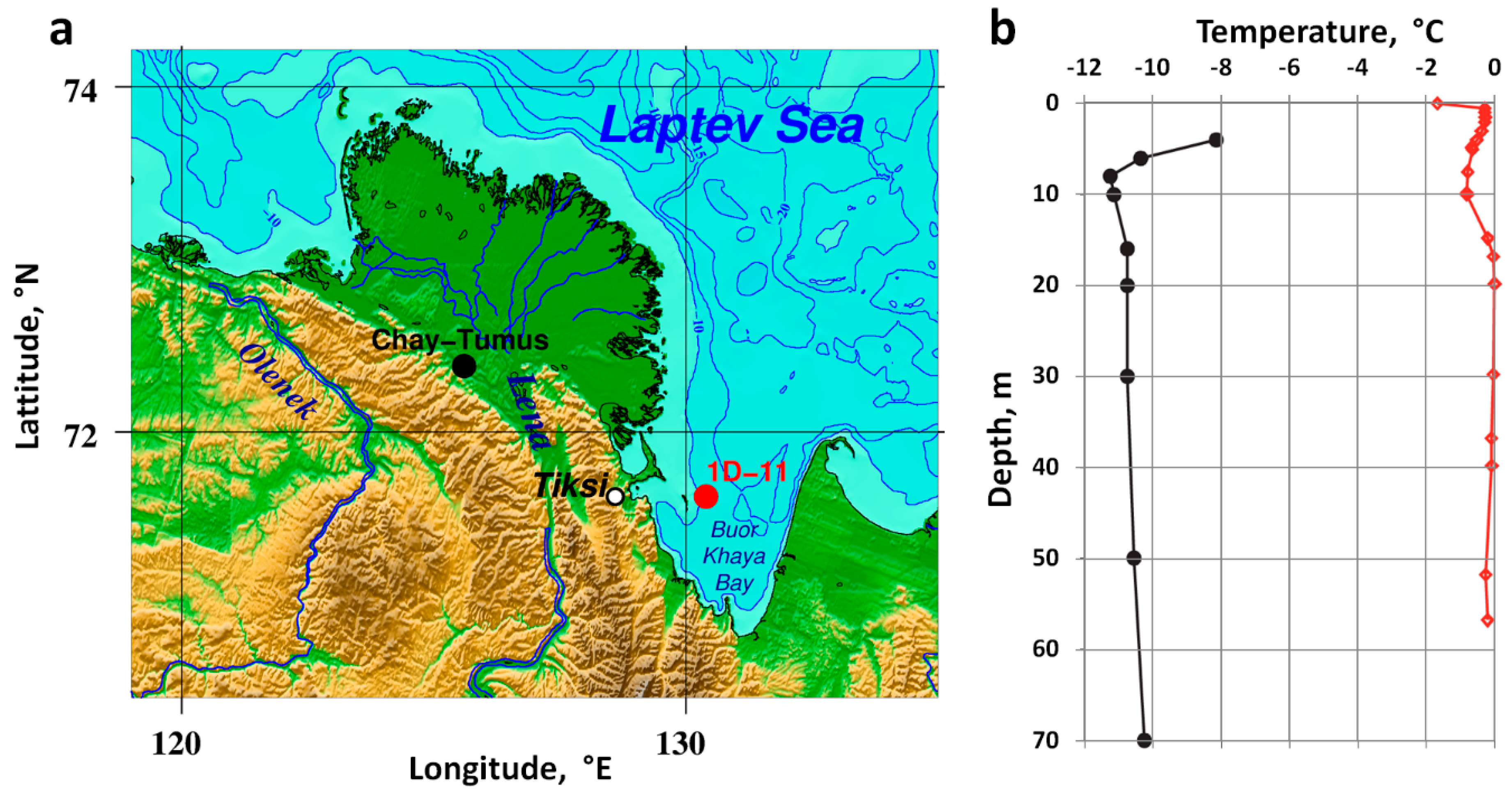
2.2. Current State of Subsea Permafrost

ESAS permafrost stability is the key to whether pre-formed CH4 sequestered in hydrate deposits escapes to the overlying strata. Warming of the ESAS began >12 thousand years (kyr) ago at the beginning of the Holocene after the ESAS was inundated by sea water due to rising sea level. Terrestrial permafrost in the Holocene Arctic experienced a change in its thermal regime caused by a 6–7 °C mean annual air temperature increase since the last glacial maximum [31]. Subsea permafrost has been subjected to additional warming induced by sea water; in the ESAS, sea water is much warmer than air (mean annual air temperature of −10 °C vs. mean annual sea water temperature of −1 °C). Consequently, the subsea permafrost has warmed by up to 17 °C during the last 12 kyrs [23,32]. It has been suggested that the following factors determine the evolution of subsea permafrost after inundation: duration of submergence compared to duration of previous exposure above the sea surface; thermal state and thickness of permafrost before inundation; coastal morphology and hydro- and lithodynamics; shoreline configuration and retreat rate; pre-existing thermokarst (thermokarst is the process by which characteristic landforms result from the thawing of ice-rich permafrost or the melting of massive ice) accompanied by formation of thaw lakes; bottom water temperature and salinity; and sediment composition, including ice content [5,11,22,28,33,34].
Until very recently, understanding of the current thermal state and stability of the subsea permafrost–hydrate system in the ESAS was primarily based on modeling results [11,23,26,35,36,37]. Two basic mechanisms based on numerical modeling were proposed to explain permafrost dynamics after inundation: the so-called “upward degradation” under geothermal heat flux in the areas underlain by fault zones [23], and the so-called “downward degradation” under the warming effect of large river bodies [26]. The latter is accelerating due to sea-ice loss and increasing warm riverine water input and contributes to warming subsea permafrost [20,25,35,36]. As a result, the thermal regime of subsea permafrost is up to 10 °C warmer than that of the same permafrost body remaining on land (Figure 3).
By the time of inundation, thermokarst caused formation of pronounced thermokarst features and development of numerous thaw lakes underlain by taliks [11]. A talik is a layer or body of unfrozen ground in a permafrost area, in which the temperature is above 0 °C due to the local thermal regime of the ground [39]. It has long been accepted that the Arctic bottom seawater (T < 0 °C) would halt further thermokarst development and cause taliks to freeze by creating a negative temperature profile in the sediments [11,28,40]. However, recent observational data collected from the near-shore area of the ESAS showed that submerged thaw-lake taliks may not freeze; instead, they may keep developing, creating pathways for ascending gas [21,22].
Trying to explain the possible survival of former thaw-lake taliks after inundation, some authors suggested that salt transport into the sediments could be orders of magnitude greater than heat conduction from the surface, altering the freezing point of sediment pore water and preventing freezing of the submerged thaw-lake taliks even in ice-bonded permafrost [41,42,43]. A significant area of the ESAS is affected by paleo-river valleys; therefore, heat flux from large rivers was also suggested to cause deep talik formation beneath riverbeds [26,44].
Destructive processes associated with coastal ice-complexes, such as thermo-denudation, thermo-abrasion, and chemical- and current-induced seafloor erosion, could also advance the development of top-down permafrost degradation [45,46,47]. In the areas underlain by the faults, groundwater flow through coastal sediments could be another possible mechanism for preventing taliks from freezing and/or causing so-called tectono-genic talik formation [22,48].
These taliks could be identified by groundwater discharge that could be manifested as large point sources, which are temporally and spatially variable and could have a significant impact on the geochemical parameters of coastal waters [49]. Releases of groundwater, including intra-permafrost water, might lead to formation of taliks within subsea permafrost, as was observed in the near-shore area of the ESAS by [22]. Based on results of the first comprehensive scientific re-drilling, it was shown that subsea permafrost in the near-shore area of the ESAS has exhibited downward ice-bonded permafrost table (IBPT) movement of ~14 cm y−1 during the last 30 years vs. ~6 cm y−1 in earlier years since inundation [22]. These rates indicate significant enhancement of the permafrost disintegration process during the last three decades. The temperature of the sediment core extracted from the subsea borehole varied from −3 °C to +1 °C [22]. In one sediment core, drilled in 2011 down to 57 m below the sea floor, the surface sediment layer exhibited the lowest temperature of −1.8 °C, but was entirely unfrozen due to very high salt content. Lower sediment layers were also unfrozen despite the low level of mineralization in the sediments. For comparison, an on-land sediment core obtained from the Chay-Tumus borehole was 8–12 °C colder than that recovered in our study [22,38].

3. Arctic Hydrates in the ESAS

3.1. History of the Topic

A question about the possible existence of gas accumulations within permafrost in other than free gas form was first raised in the mid-1950s, when gas blowouts occurred during exploration of natural resources in permafrost areas of Russia that hurt people, damaged equipment, and became a real problem [45,50]. Later, the results of larger-scale exploration consisting of eight campaigns performed across the Russian north became partially available to scientists. Tens of boreholes were drilled in each of eight areas where exploration of different types of natural resources had taken place. Similar gas blowouts were reported in Alaska and in the Arctic regions of Canada [51,52,53]. Scientists were intrigued by specific features of these gas blowouts. (1) Gas was released from shallow depths, starting from as shallow as 20 m [52,54]; (2) gas blowouts occurred in areas where no remarkable gas/oil resources were predicted to exist beneath the permafrost [50]; (3) gas blowouts were discharged from sediments of different ages, from modern to ancient, and from sediments of different types, sand, silt, and clay [55]; and (4) volumes of gas released during blowouts exceeded by many times the volume of pores, which were entirely filled with ice [52,53].
The thickness of permafrost at all eight sites was more than a few hundred meters, which excluded the possibility that blowout-feeding gas traveled to the wells from gas accumulations preserved beneath the permafrost; ice-bonded permafrost is considered nearly impermeable for gases. Analysis revealed that the sampled gas consisted of 78.3–99.8% CH4; heavier hydrocarbons were detected at two of the eight sites (0.01–0.07%) [56]. The isotope signature of CH4 in the majority of samples indicated biogenic (microbial) gas (δ13C from −70.4‰ to −74.6‰); in some samples, thermogenic CH4 was identified by the presence of heavier hydrocarbons such as ethane (2–5%), propane and butane (0.5–3%), and bitumen [57]. Gas blowouts were followed by continuing gas flows measured at from 5 × 10² to 5 × 10⁵ m3 d−1 which lasted up to seven months in some areas. In one observed well 5 × 10⁷ m3 (2.1 Tg) of CH4 was released over 11 months [57]. It was suggested that the gas blowouts resulted from hydrate breakdown caused by the decrease in pressure accompanied by hydrate exposure to warmer conditions resulting from drilling.

3.2. Mechanism of Arctic Hydrate Origination

Observational data became a subject for theoretical and experimental work starting from the 1980–1990s. Experimentally it was shown that hydrates formed at T << 0 °C are stable at P << 25 atm [52]. Such pressure could occur in the inter-pore space during ground/sediment freezing. A four-step mechanism was proposed to explain how inter-pore hydrates form within permafrost when pore water in sediments freezes: (1) The temperature of ground/sediments exposed to low temperatures drops below 0 °C; (2) as pore water freezes growing crystals occupy the entire pore space; (3) dissolved gas, along with minerals, is ejected from the ice due to limited inter-pore space; (4) the resulting inter-pore space pressure increases many fold; and 4) when pressure reaches the thermodynamic threshold, inter-pore hydrates form within permafrost [52].
It was suggested that these processes could occur in permafrost on a wide scale but could be restricted by lack of water or gas in sediments. Inter-pore hydrates are considered metastable, because they form outside of the conventional hydrate stability zone (HSZ) of Arctic hydrates, which in permafrost areas on-land usually is usually located at the lower boundary of permafrost; only there do sediments remain unfrozen (T ≥ 0 °C) and free gas from accumulations formed beneath the permafrost converts into hydrates [52,56,58,59]. Unlike the hydrates within the conventional HSZ, permafrost-related hydrates are energetically more efficient because the amount of energy required to form/destabilize hydrates at T ˂ 0 °C is only one third of the amount required to form/destabilize hydrates at T ˃ 0 °C (18.1 ± 0.3 kJ M−1 vs. 54.2 ± 0.3 kJ M−1, [60]). Inter-pore and relic hydrates were observed at ground depths as shallow as 20 m [61,62], but were shown to survive better in permafrost at depths ˃60 m [63].
Relic hydrates form as a result of “self-preservation”, a term first introduced by Russian scientists after they observed that hydrate dissociation slowed and stopped after hydrate particles became coated with ice films. The self-preservation phenomenon was described in works by [52,55,58,62]. During the last two decades, research has focused on studying the self-preservation phenomenon and the kinetics of metastable (relic) and porous hydrates at temperatures below 0 °C [64,65,66]. These studies showed that self-preservation in porous hydrates depends on host sediment properties, hydrate structure and saturation, salt and ice content of pore water, etc. [67,68]. Stability of these hydrates in the ESAS is determined by the dynamics of coupled pressure/temperature (P/T) conditions, which change drastically during the repeated freeze–thaw cycles experienced by a permafrost–hydrates system in glacial–interglacial epochs.
A change in the thermal regime of a permafrost–hydrate system after its submergence would lead to partial thawing of permafrost, causing destabilization of intra-permafrost hydrates; this would be manifested as patchy (mosaic, spotty) gas releases over the destabilized areas [5,14,15,21,68]. The fraction of intra-permafrost hydrates was suggested to not only survive the thawing cycle due to the self-preservation phenomenon, but also to become denser and more saturated owing to recrystallization caused by repeated freeze–thaw cycles [69]. On the other hand, salt propagating into the permafrost as brine increases the content of unfrozen water, which is unfavorable for metastable hydrates stability [69]. Specific features of Arctic hydrates include: (1) Occurring three times more frequently offshore than onshore [13]; (2) high spatial concentration and thick layers (up to 110 m); (3) extremely high pore saturation, up to 100% of pore space [13]; and (4) higher sensitivity to warming and lower sensitivity to pressure change [63,70].

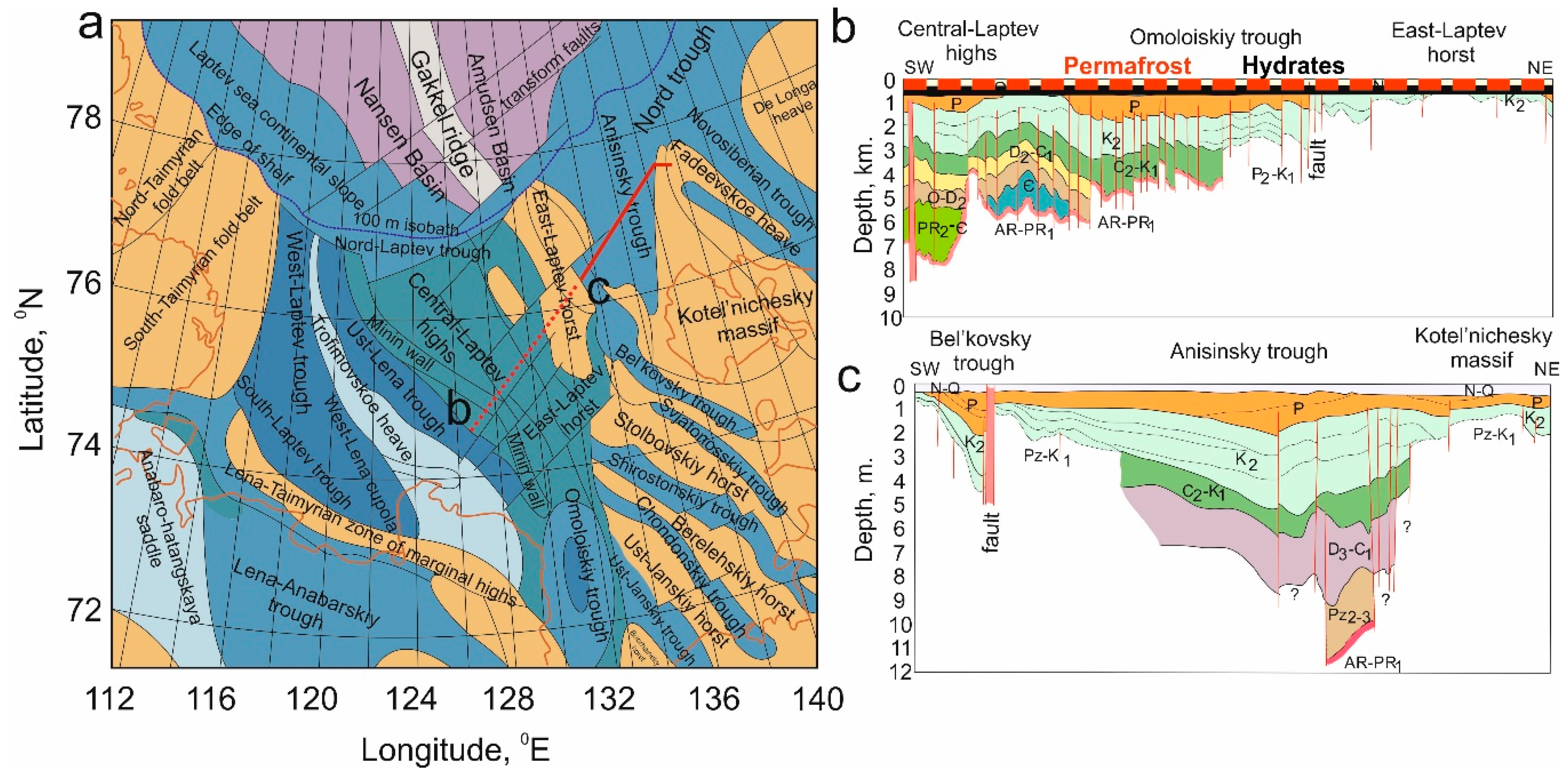
3.3. Principal Scheme of the Permafrost–Hydrates System

As was shown above, the subsea permafrost–hydrate system in the ESAS formed as a result of repetitive transfers from a dry to a submerged position caused by sea level drop-rise as glacial–interglacial climate epochs alternated. Initially, the ESAS was a part of the continental shelf of the AO. Like on other continental shelves, in the ESAS seabed hydrate deposits can originate where gas supply and P/T conditions allow stability of these deposits within the so-called HSZ (Figure 4a). The major misunderstanding is that hydrostatic pressure (pressure created because a water column exerts downward force) alone is responsible for providing the P conditions required for an HSZ to form in the marine environment; from this it follows that an HSZ might form only in shelf areas, where water depth is ˃250 m, which creates P ˃ 25 atm (if T ≤ 0 °C). According to [5,14], the lack of hydrostatic pressure created by a water column ˂250 m deep could be compensated for by geostatic pressure, pressure created by the sediment column overlying the HSZ. This implies that the water depth in the shallow shelf determines how deep beneath the sea floor the upper boundary (UB) of the HSZ can occur. If the water depth is 200–250 m and the T ≤ 0 °C, the UB of the HSZ would occur at the sea floor; if the water depth is shallower, then the UB of the HSZ would occur as deep below the sea floor as is required to meet the required P/T conditions. For example, if the water depth in the ESAS is ~50 m, the UB of the HSZ would occur at ~100 m below the sea floor (if sediment density is ~2 g cm3) [5,14].
Permafrost (frozen ground with a two-year mean subzero temperature) and associated permafrost-related Arctic hydrates in the ESAS first originated during cold climate periods, when sea level dropped more than 100 m lower than it is today; consequently, the coastline extended as much as 1000 km further north, exposing the entire shelf area above the sea surface and, thus, increasing the area of the Siberian coastal accumulative plain by a factor of five [11]. Exposed to the low Arctic surface temperatures, marine sediments were subjected to a drastic change in their thermal regime—cooling by as much as −28 °C [28]. This led to freezing of the uppermost few hundred meters of sediments; as a result permafrost formed, covering the upper few hundred meters of the sedimentary drape with an impermeable cap (Figure 4b). Additionally, freezing of marine sediments and formation of permafrost caused a change in the P/T conditions of previously originated hydrates; shelf hydrates had existed in marine conditions before the shelf was exposed above the sea. As a result of this drastic change in thermal regime shelf hydrates and gaseous CH4 pre-formed in marine sediments gradually turned into permafrost-related hydrates (or Arctic hydrates), which might exist within the HSZ (conventional Arctic hydrates, Figure 4b) and/or outside the HSZ (inter-pore, porous, and/or relic hydrates, Figure 4b), and which may partially survive freeze–thaw cycles during the alternating glacial–interglacial climate periods [63].
After a sea level rise during the inter-glacial climate epochs by up to 120 m, the entire area of the ESAS was submerged (Figure 4c); the last replacement of the cold epoch by the current warm epoch (Holocene) led to permafrost inundation about 12 kyr ago [66]. Inundated together with permafrost, which became subsea permafrost after inundation, the Arctic hydrates (of terrestrial origin) became the unique shallow Arctic shelf hydrates—that is, hydrates existing where the water depth in the Arctic shelf is <200 m. Since the time of inundation, the permafrost–hydrate system has been forced to undergo transformations determined by drastic changes in the thermal regime of the surrounding environment. Indeed, due to inundation, permafrost, with a mean annual temperature upon origination of around −17 °C, achieved a new mean annual temperature under seawater of ≥−1.8 °C [10,11], reaching a new quasi-stationary temperature equilibrium with the surrounding environment [5,6].
Different ESAS areas required different times to reach this equilibrium, depending on shelf floor relief, duration of inundation, and duration of preceding exposure above sea level; these factors determined permafrost thickness, and permafrost thermal regime as well as stability and capacity of associated hydrate deposits [5,14]. In response to warming under seawater, the permafrost–hydrate system started destabilizing. This destabilization is manifested by shrinkage in the HSZ near the subsea permafrost bottom and partial decay of inter-pore hydrates due to change in P/T conditions. Some gaseous CH4 converted from inter-pore hydrates started its upward movement but the major fraction was converted back to so-called metastable relic hydrates, which accumulate at depths <100 m due to the self-preservation phenomenon. This preservation allowed hydrates to survive during the short thaw cycles until inter-glacial epochs were replaced by glacial epochs. However, in places where geothermal heat flux was greater than on the rest of the shelf area and where permafrost was affected by thermokarst before inundation, partial destabilization of these hydrates was possible, allowing CH4 release to the overlying strata (Figure 4d).
Alternating glacial–interglacial epochs led to repetitive changes in the thermal regime of the permafrost–hydrate system, with corresponding changes in system stability and integrity; such alternations are known to exist within at least four of the last climate cycles, or for ~400 kyrs [1]. During a normal climate cycle, like the Eemian which began about 130,000 years ago and ended about 115,000 years ago, the interglacial thermal maximum and associated high sea level stand usually lasted 1–2 kyrs, not long enough for permafrost to reach thermal equilibrium with the surrounding environment and start losing its integrity. This enabled the permafrost–hydrate system in the ESAS to return from state (c) to state (b) (Figure 4). The current inter-glacial epoch (Holocene) exhibits continuing warming associated with a long-lasting sea level high stand (˃5 kyrs) [1,71]. Because approaching the phase-transition point (thawing) can only be possible after permafrost reaches an equilibrium state with the surrounding environment, which requires ˃˃1–2 kyrs, the additional duration of the warming effect of seawater makes a critical contribution to the process of permafrost–hydrate system destabilization [5].
As a result, continuing warming causes not only advanced deepening of the IBPT but also thaw-through disintegration of the permafrost body at places such as fault zones, paleo-rivers, areas affected by thaw lakes, freshwater seepages into shelf sediments, and so-called pingo-like features, which provide subsea permafrost with heat and create migration pathways for CH4 that is released from destabilizing hydrates [72,73,74]. A pingo is a mound of sediment-covered ice. The HSZ continues to shrink and forces deeply buried CH4, long preserved in hydrates, to be released as overly-pressurized free gas, which escapes to the overlying strata as bubble plumes [21] and ascending gas fronts [22], and could reach the atmosphere. In addition, propagating heat and salt from cryopegs causes breakdown of metastable hydrates; this breakdown releases bubbles of CH4 to the water column. A cryopeg is a layer that remains unfrozen due to high salt content. Emissions from the ESAS to the atmosphere could therefore be increasing (Figure 4e). A return from the state described in panel 4(d) to the state described in panel 4(c) is only possible if warming is replaced by cooling. Returning to the state shown in 4(a) is impossible, because the state shown in 4(a) remains hypothetical—this implies returning to the state when the ESAS was never exposed above sea level and, thus, was never subjected to conditions that allow the existence of specific types of hydrates that exist exclusively in the Arctic shallow shelf region.

4. Specific Features of CH4 Releases in the ESAS (1994–2017)

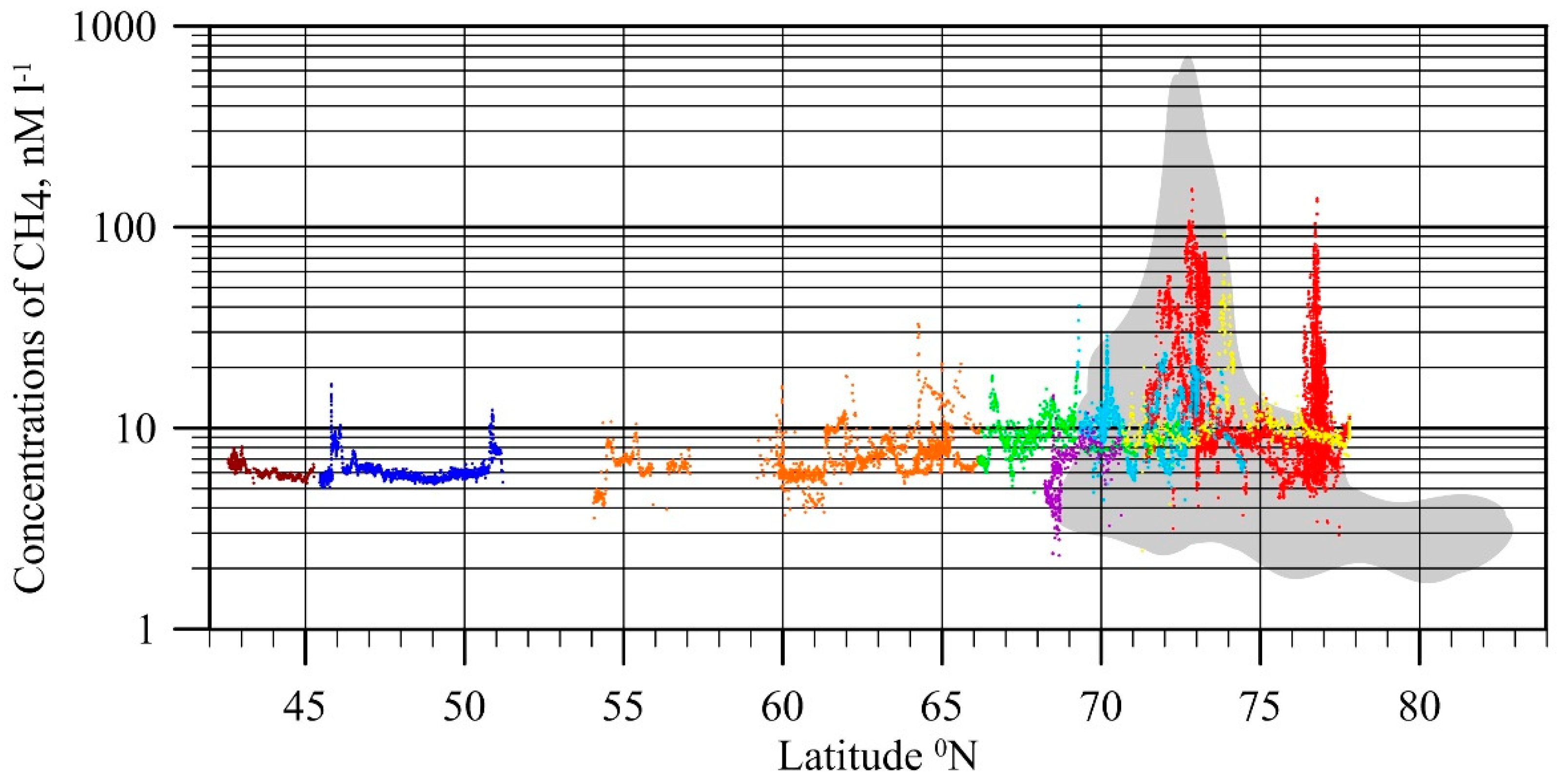
4.1. Flux Assessment Based on Observational Data

The initial phase of dissolved CH4 studies in the ESAS took place from 1994 to 2000. In 1994–1996, the study area was limited to the vicinity of the Lena Delta; in 2000, a summer cruise was conducted along the coast from the White Sea through the Kara Sea to the ESAS. The analytical techniques employed during that period had a detection limit of about 15 nM of dissolved CH4 in seawater [27]. Due to this limit, no CH4 was detected in most of the >400 seawater samples that were analyzed during three cruises. The dissolved CH4 concentration in only one sample, collected in the near-shore area of Buor-Khaya Bay, was measured to be >20 µM. Therefore, despite that single outlier, it was concluded that shelf water did not serve as a source of CH4 to the atmosphere [27].
From 2003 to 2016, seasonal expeditions to the ESAS were performed annually in summer; in addition, in 2007 and from 2011–2015 winter drilling campaigns were complemented with oceanographic surveys performed from the fast ice in the near-shore area of the Laptev Sea. Continuous measurements of dissolved CH4 along the ship’s track were made in the surface water, not only in the ESAS but also in the surface water of other Russian Arctic and sub-Arctic seas including the Barents Sea, the Kara Sea, the Laptev Sea, the East Siberian Sea, the Chukchi Sea, the Bering Sea, the Sea of Okhotsk, and the Sea of Japan [75]. These data fall within the range of previously reported concentrations of dissolved CH4 measured in the water samples collected by Niskin bottle as described in [16,19]. The combined data set shows that surface waters of the ESAS generally were supersaturated with dissolved CH4 as compared to other seas (Figure 5).
Based on the initial data set (2003–2008) and preliminary understanding of the factors controlling annual emissions, an attempt was made to estimate the total annual CH4 flux from the ESAS [19]. Six separate components of the total flux budget were considered to account for differences in ice coverage (summer versus winter) and mechanism of CH4 transport in the water column (diffusive versus ebullition) integrated over the areal extent of the two regions with different source strengths (background versus hotspots) [19]. The total annual venting flux of ~8 Tg C–CH4 from the ESAS to the atmosphere was calculated, which did not include ebullition from the seep fields, because understanding the role and contribution of bubble-borne CH4 at that time was insufficient due to lack of observations. A general change in focus to investigating ebullition occurred in 2009, after we hydro-acoustically recorded several flare-like structures that stemmed from the sediments, creating subsurface CH4 maxima in the seawater [20,21].
During expeditions in two consecutive years (2009 and 2010) we confirmed a storm ventilation mechanism, i.e., storm-driven water column and atmospheric boundary layer CH4 reservoir depletion, followed by rapid replenishment; this pointed to an intrinsically strong seabed CH4 source which releases CH4 to the water and atmosphere via ebullition [20]. By combining estimated seep intensity and density class emission rates, we estimated 290 mg m−2 d−1 ebullition-induced flux (ranging from 100–630 mg m−2 d−1). This mean flux is >10 times greater than was previously suggested for ESAS hotspots [19]. These observations provided an opportunity to constrain the bubbling CH4 flux from shallow ESAS hotspots. Given that the study area covered ~10% of the ESAS hotspots, storm-caused and bubbling CH4 flux from ESAS hotspots to the atmosphere were estimated at 9 Tg CH4 annually, increasing the estimate of total ESAS CH4 emissions to the atmosphere to 17 Tg yr−1 [20].
To quantify CH4 fluxes conveyed by bubbles being released from the seafloor, in 2011–2012 we implemented a down-scale-to-up-scale approach, in which we aimed to combine the advantage of the accuracy that was achieved by evaluating CH4 flux using direct seep observations, with the advantage of the wide area coverage that was achieved by collecting bubble-imagery sonar data. To interpret sonar data, we performed an in situ calibration that aimed to establish a relationship between the backscattering strength of CH4 bubbles and gas flux rate. Results achieved by use of in situ calibration were validated by comparing these results with those obtained based on direct in situ observations of CH4 bubble flow [21]. By detecting >700 individual seeps, including large bubble streams continuously rising through the water column (that is, flares), and analyzing >1000 records of bubbles, the radii of which varied from 1 mm to 10 mm, and assuming steady flux was maintained ~50% of the time, we estimated a mean flux of 0.044 mmol-CH4 s−1, corresponding to 3.4 mol-CH4 d−1 or 54.4 g d−1 from one outlet.
This implies that areal flux would vary many fold or even by orders of magnitude depending on the number of outlets within the seepage area [21]. We calculated mean CH4 fluxes from small, medium, and large flare seep fields to be 30.8 g CH4 m−2 d−1, 88 g CH4 m−2 d−1, and 176 g CH4 m−2 d−1, respectively. In October 2013 we performed observations in the southernmost part of the Laptev Sea, in Ivashkina Lagoon, which has been progressively inundated during the last ~100–500 years, replacing a former thermokarst lake. Bubble release occurred from narrow, steep depressions aligned parallel to the lagoon’s northern edge. Backscattering cross-sections of the bubbles emitted from 17 seeps observed in Ivashkina Lagoon were recorded for 36 hours using portable single-beam sonar, which was calibrated in situ during the same campaign. In Ivashkina Lagoon, CH4 fluxes observed in October 2013 ranged from 5 to 24 g m−2 d−1 [21].

4.2. Flux Attribution to Permafrost State and Source Contribution

To attribute CH4 fluxes to the current state of subsea permafrost, we aimed to induce the range of modern fluxes, observed over the ESAS shallow-, mid-, and outer-shelf areas. It was important to incorporate fluxes from the outer ESAS shelf with water depth >50 m, where permafrost has presumably degraded the most, because seawater started to submerge this area ˃12 thousand years ago at the beginning of the Holocene [11]. Thus, it was logical to assume that CH4 flux from this area would represent the maximum possible CH4 flux in the ESAS and indicate the potential for flux increase if ESAS permafrost thawing progresses. Data accumulated in the ESAS over the last 15 years show very high variability of CH4 fluxes (3–5 orders of magnitude) in the ESAS (Figure 6). This supports the hypothesis that CH4 fluxes depend on the current state of subsea permafrost rather than on rates of modern methanogenesis, because concentrations of Corg in the surface sediments of the ESAS vary only by a factor of four while CH4 fluxes vary by orders of magnitude (Figure 6).
The range of modern CH4 emissions serves as a baseline for monitoring future dynamics in CH4 fluxes from the ESAS. We suggest that within the entire range of observed fluxes, the lowest rates (≤3 mg m−2 d−1) are associated with an initial degree of subsea permafrost thawing observed in the shallow- and mid-shelf outside the areas affected by faults, rivers, and pre-existing thermokarst (Figure 6). These fluxes are likely fueled by modern methanogenesis occurring within sediment accumulations of Holocene age, which have never been frozen, and/or within partially-thawed older sediments beneath them; these fluxes are usually attenuated by CH4 oxidation in the uppermost layers of sediments within the sulfate-reduction zone. The isotopic signature of this biogenic CH4 that originated from Corg of Holocene/pre-Holocene age is rather specific for the Arctic region. Initial δ13C could vary from −120‰ to −90‰, implying that fractionation occurs at very low temperatures; however, the resultant isotopic signature of sampled CH4 could be altered by numerous processes (mixing, oxidation, transportation, dilution, etc.), to which released CH4 is subjected during its lifetime in the sediment–water environment [74,76,77].
The medium rates (3–30 mg m−2 d−1) are determined by modern methanogenesis combined with partial release of pre-formed CH4 from inter-pore and/or relic hydrates preserved within the permafrost. At places where subsea permafrost thawing in the ESAS occurs in the areas affected by faults, rivers, and pre-existing thermokarst, and where occurrence of deep/open taliks could be expected, CH4 would be released from a partially destabilized HSZ, where CH4 could equally be of thermogenic and biogenic origin. The isotopic signature of this CH4 would most likely represent a mixture of both—possibly thermogenic CH4 released from the HSZ (a minor fraction), biogenic CH4 released from inter-pore space and/or relic hydrates originating from old Corg of Pleistocene age, and modern CH4 originated from Holocene Corg: δ13C from −50‰ to −75‰. Again, alteration of isotopic signature is possible during the lifetime in the sediment–water environment [77].
The highest rates (30–176 g m−2 d−1) likely represent the maximum emissions currently taking place from the outer shelf, which include a combination of modernly-produced CH4 of Holocene age, long-accumulated pre-formed CH4 escaping from inter-pore and/or relic hydrates, originated from old Corg of Pleistocene age. Resultant isotopic signatures would trend towards heavier numbers (δ13C ˃ −50‰) and, depending on longevity and intensity of the altering processes, could even be unusual. The observed range in CH4 emissions associated with different degrees of subsea permafrost disintegration implies substantial and potent emission enhancement in the ESAS as the process of subsea permafrost thawing progresses coastward with time. While it is still unclear how quickly CH4 flux rates will change, the current process of Arctic warming and associated sea ice loss will accelerate this process.

4.3. Factors Controlling CH4 Emissions

Sea ice serves as a natural physical barrier that restricts CH4 emissions from the ESAS during the ice-covered period. Because temperature in the Arctic has increased at twice the rate as in the rest of the globe, and the region is expected to increase an additional 8 °C in the 21st century [1], longer periods of open water and shorter ice-covered periods will become the norm [78,79]. Considering that during the winter ice-covered period the majority of CH4, which in summer escapes directly to the atmosphere, accumulates beneath the ice, and that the ice-covered period is ~3 times longer than the open water period, CH4 flux during ice break-up could be substantial. This flux could be slightly attenuated due to CH4 oxidation within the water column. It was shown that CH4 oxidation time could vary from 36 days near the Lena Delta [80] to up to 1000 days further offshore [21]. Fall convection in late September and early October is particularly important because at this time, the probability of convection penetrating down to the seafloor can reach 40–50% over the total area of the ESAS; in shallow waters (<20 m) such probability can reach 100% [20,81]. This implies not only that CH4 which has accumulated in the surface water layer could be released to the atmosphere, but also that the amount of CH4 which has accumulated within the entire water column during the summer could be released to the atmosphere.
Increasing periods of open water implies an increasing number of storm events, when wind speed increases to ≥15 m s−1 and the boundary between sea surface and air increases many fold due to deep water mixing. Such events have the potential to rapidly ventilate bubble-transported and dissolved CH4 from the water column, producing high emission rates to the atmosphere. Because >75% of the total ESAS area is <50 m in depth, the water column provides bubbles with a very short conduit to the atmosphere. Storms enable more CH4 release because they destroy shallow water stratification and increase the boundary between sea surface and air, thus increasing gas exchange across phase boundaries. As a result, storm-induced CH4 “pulses” force a greater fraction of CH4 to bypass aqueous microbial filters and reach the atmosphere [20].
In addition, about 10% of the ESAS remains open water in winter due to formation of flaw polynyas. Formed simultaneously with land-fast ice in November, flaw polynyas propagate out of fast ice hundreds of kilometers north [82]. Flaw polynyas provide pathways for CH4 escape to the atmosphere during the arctic winter [17]. Areas of flaw polynyas in the ESAS increased dramatically (by up to five times) during the last decades [83], and now exceed the total area of Siberian wetlands [84] (Figure 7). This implies that the ESAS remains an active source of CH4 to the atmosphere year-round, even in the winter when terrestrial Arctic systems are dormant. Increasing storminess and rapid sea-ice retreat causing increased CH4 fluxes from the ESAS are possibly new climate-change-driven processes. Continuing warming of the AO will strengthen these processes, and the role of the ESAS as a year-round contributor to global CH4 emissions will grow over time. The ESAS is a tectonically and seismically active area of the WO [85,86]. During seismic events, a large amount of over-pressurized gas can be delivered to the water column, not only via existing gas migration pathways, but also through permafrost breaks that can occur within otherwise continuous permafrost or pingo-like structures observed over the Arctic shelf [73].

4.4. Contribution of the ESAS to Global Hydrate Pool

The potential for the release of substantial amounts of CH4 from the ESAS region has important implications not only for atmospheric CH4 concentrations but also, given CH4’s potency as a greenhouse gas, for global climate. Because the ESAS contains the largest and arguably most vulnerable stores of subsea CH4 in the world, inclusion of the ESAS source in global climate models should be considered a high priority. However, there is a perception that the amount of Corg preserved in the ESAS is too insignificant [87] to cause any noticeable disturbance to the climate system [8]; this point of view requires further clarification for several reasons. First, even though the AO composes only 4% of the WO’s area, its continental shelf comprises ˃20% of the WO continental shelf. Up to 90% of Corg, which provides a substrate for CH4 production, is located on the WO continental shelf [88].
Sediments and incorporated Corg, which determine areal occurrence of hydrate deposits, are not distributed equally over the WO. The sediment drape in the pelagic area of the WO is only ~1 km thick, while on the continental shelves it reaches ~3–4 km; concentrations of Corg vary over the WO sediments by a factor of 10, with the lowest levels found over the pelagic area of the WO (~80% of the WO) and the highest levels found in the sediments on the continental shelf of the AO (Figure 8). Among all the continental shelves of the WO, the ESAS is the largest and its sedimentary drape reaches up to 15 km thick with high concentrations of Corg distributed throughout. Because the ESAS composes ~8% of the WO continental shelf, its sedimentary drape area- and thickness-weighted fraction alone could contain 15 to 20% of global Corg inventory; Corg provides the substrate for CH4 production. The entire Arctic shelf could contribute two- or three-fold more Corg than does the ESAS.
Anywhere in the WO where P/T conditions permit the existence of an HSZ, there are generally no impediments to the HSZ’s release of excessive CH4 to the overlying strata during the life time of the HSZ; it is known that an HSZ is a dynamic system that allows gases to flow in and out [89]. In the areas of the WO where the upper layers of the sediment drape are preserved within permafrost, this subsea permafrost seals the underlying sediments so that the gas outflow from the HSZ and underlying sediments, where free gas accumulations could exist, is severely restricted due to the relative impermeability of permafrost for gases. This implies that gas accumulations within permafrost and below permafrost in the HSZ remain preserved for a long time (for duration of the glacial epochs).
The ESAS is the region of the WO where ˃80% of the world’s predicted subsea permafrost and associated permafrost-related hydrates exist. It was suggested that ˃1400 Gt of CH4 could be preserved in the seabed of the ESAS [90]. The current annual emission of CH4 to the atmosphere was calculated to be between 8 and 17 Tg annually [19,20]; this implies, conservatively, that equal amounts could have been potentially released annually during the previous climate epochs if permafrost had not restricted CH4 flux. Therefore, due to such restriction, during the time of one glacial period (~100 kYrs) ˃800 Gt of CH4 could have accumulated in the ESAS seabed as postponed potential fluxes. This amount of pre-formed gas preserved in the ESAS suggests a potential for possible massive/abrupt release of CH4, whether from destabilizing hydrates or from free gas accumulations beneath permafrost; such a release requires only a trigger.

5. Discussion and Outlook

It has been two decades since investigations of CH4 emissions from the ESAS began [19,27] and slightly over a decade since the topic of the possible role of degrading subsea permafrost and Arctic shelf hydrates in CH4 emissions from the ESAS was introduced to the scientific community [16]. Since that time, only one group of scientists has been studying this topic on a regular basis. Over a 15-year period more than 40 annual expeditions were conducted, including marine cruises in summer and oceanographic expeditions/drilling from the fast ice in winter. Thousands of water, sediment, and gas, and countless air samples were collected and analyzed to evaluate the variability of dissolved and atmospheric CH4 in different areas of the ESAS and to assess the isotopic signature of contributing sources using triple-isotope analysis (13C, D, and 14C). As a result of this effort an unprecedented data set was accumulated; it provides the best coverage ever reported for any area of the WO (Figure 9).
Some experimental work has been performed to investigate subsea permafrost physics, establishing the basis for improved modeling of subsea permafrost and associated processes. Nevertheless, the remaining gaps in our knowledge of the physical and chemical processes occurring within subsea permafrost, combined with a lack of factual data for model calibration, restricts further improvements of ESAS subsea permafrost modeling [22]. There is a need to accomplish experiments on bubble propagation in the water column to enable quantifying the fraction of CH4 that could reach the atmosphere from different water depths. To understand the current state and future dynamics of the subsea permafrost–hydrate system, we must develop methods that allow us to distinguish between frozen and unfrozen sediments, hydrates within frozen sediments (porous, inter-pore, relic), gas migration paths, and taliks.
This is challenging, because to date there are no reliable geophysical methods available to accomplish this task. The position of the IBPT and rates of permafrost degradation could be evaluated by assessing changes in the permafrost table position relative to the seafloor. In the ESAS, the permafrost table position has been investigated using seismic techniques [91,92]. However, there are numerous problems due to high attenuation of the reflected seismic signal where sediments contain gas [93] and/or due to variability in permafrost properties in frozen vs. unfrozen permafrost zones [94]. Methods based on electrical properties of frozen vs. unfrozen ground were shown to be applicable in shallow coastal water, but results of these surveys require thorough validation by observational data [22,95]. Recently reported results [68] presented evidence for widespread occurrence of gas hydrates across water depths of 60–100 m on the shelf of the Canadian Beaufort Sea using 3D and 2D multichannel seismic data. However, any interpretation of data obtained using any methods should be validated by recovered sediment core analysis; this implies that widespread scientific drilling is required over the entire Arctic shelf, not only in the ESAS, in order to recover a sufficient number of sediment cores representative of different types of sediments and geological settings. Microbiological studies and multi-dimensional isotope analyses of released CH4 is one avenue to follow in order to apportion the CH4 sources (including different types of hydrates) and to constrain the flux attenuation due to microbial oxidation of CH4.
Because this topic is rather new, some methodological issues should be taken into consideration by those performing or planning to perform investigations of the topic. We will present examples of what we view as flawed methodologies in the following section.
One methodological issue regards the knowledge and expertise limitations that affect conclusions delivered by some authors. For example, in [96], the authors made two major methodological mistakes. First, they reported CH4 oxidation without presenting actual data (either direct or indirect) to prove oxidation; they only referred to a change in the values of a stable isotope (δ13C) in CH4. However, δ13C-CH4 in sediments can vary due to numerous reasons, among which the most important is the natural variability of the 13C isotope signature of end-members, which could vary even within the same type of CH4 (biogenic or thermogenic) in a similar type of environment. Indeed, δ13C of biogenic CH4 produced in Siberian wetlands under different thermal regimes can vary from −59‰ to −110‰ [76,97]. The δ13C of thermogenic CH4 in Siberia yields a range from −15‰ to −52‰ [52]. Clearly, even a mixture of CH4 from end-members with different isotope signatures can produce numerous variations of the resultant signatures.
In addition, the δ13C of CH4 can be altered due to oxidation, transportation, dilution, cracking of heavier hydrocarbons, and other processes. For example, the observed δ13C-CH4 value of −75‰ measured in a sample could be: (1) the isotope signature of a biogenic CH4 end-member; (2) the result of a 1:1 mixture of two biogenic sources with the isotope signature of end-members equal to −60‰ and −90‰; (3) the result of CH4 oxidation with the isotope signature of an end-member equal to −110‰; (4) the result of a 1:1 mixture of biogenic CH4 with an isotope signature of −110‰ and thermogenic CH4 with an isotope signature of −40‰. These are only a few simple examples; numerous possible compositions can result from different processes and factors. To claim variability in δ13C-CH4 due to oxidation, one must present a study of actual microbiological processes or at least use indirect methods as reported in [80].
Some researchers may be unaware of the specifics associated with working with frozen/unfrozen sediment cores while performing drilling of the boreholes followed by extraction of the sediment cores. For example, in [96], the authors extracted the sediment core from the tubing with the use of an air compressor. Subsequently, to explain the difference in CH4 concentration in the frozen vs. the thawed sediment core fractions, they hypothesized that oxidation had occurred; in fact, gas had been lost because the tubing was not sealed during the extraction. Their resulting conclusion—that CH4 production mostly occurs in the frozen sediments while oxidation dominates in the thawed sediments—sounds revolutionary to any biogeochemist working in the field, because it is common sense that the thawing of permafrost would evoke CH4 production. The emitted CH4 fluxes would naturally be attenuated by CH4 oxidation in the uppermost layers of the shelf sediments, if CH4 is dissolved in the pore water and propagates by diffusion. It is important to realize that gaseous CH4 propagating within sediments as bubbles would not be consumed by methanotrophs because they only digest dissolved CH4 [98,99].
One more issue regards the level of data representativeness and the statistics applied to the analyzed data sets to enable conclusions to be drawn. Very often scientists use statistics of the most common probability distribution, a normal (Gaussian) data distribution. Sometimes they even apply these statistics as filters while collecting data without investigating the nature of the raw data first. As a result, they set a data range by removing outliers; sometimes that can be like throwing the child out with the bath water. Indeed, when one sets 1 SD (or 1 σ) as a data filter, this means that all outliers are removed and only 68% of the data is taken into consideration. Many years ago, when we started our investigation, we collected a limited data set; dissolved CH4 was not detected in most samples due to low instrument precision, and in only one sample did we measure a very high concentration of dissolved CH4 (20 µM). Following the mainstream, we removed this sample from our data set and, as a result, we lost at least five years of expertise, because, as we learned later, that single sample was from a hot spot, which we identified in that location five years later. Other authors have made the same mistake as we did, and removed outliers from the analysis [80,100]. We suggest that no statistical filters be set while collecting the raw data; this allows researchers to consider every data point when investigating the nature of the raw data. Before applying any statistics to a raw data set, it is reasonable to test the data using variable statistical tools and available software to understand which distribution fits best and what statistics is appropriate to apply. When measured values vary many fold or even by orders of magnitude, instead of removing the outlying values, it would be appropriate to divide the data into sub-populations and apply other than normal distribution statistics to the data [19].
For example, in [100] the authors reported data from a single data set collected on the joint Russian–Swedish expedition onboard Ice Breaker Oden in 2014 (Figure 9). Based on applied methodology, and despite clearly observed ebullition, they suggested that diffusive fluxes alone can explain observed atmospheric mixing ratios that are slightly elevated in some areas but much less than those reported for shallow inshore areas. However, from the presented data it follows that in the investigated areas of the ESAS all measured concentrations of atmospheric CH4 were above the latitude specific monthly mean of 1.85 ppm and concentrations of CH4 in a majority of the surface water samples were above the saturation level, reaching up to 250 ppm of CH4 (≈400 nM). One of the authors of the current paper participated in the 2014 IB Oden expedition, and all participating researchers began to write the paper later published by [100]. The published authors of [100] reported the atmospheric and aqueous CH4 data sets that were treated in accordance with the authors’ methodology, the shortcomings of which are described below.
This methodology was flawed in the following ways. (1) Methods used to measure both atmospheric mixing ratios and concentrations of dissolved CH4 were not calibrated; that is, they did not estimate the time required for sample equilibration before determining the measurement frequency. Because time of equilibration was longer than the time between measurements, they measured unequilibrated samples, and measured levels were lower than they would have been if samples had been allowed to equilibrate. (2) While collecting the raw data, 1 SD from the mean was set as a data filter; as a result, all outliers, which are values of major interest when studying ebullition, were removed and only 68% of the observed values were used for analysis. This corrupted the data range and the applied statistics, because the atmospheric mixing ratios of CH4 in fact varied by up to 4.2 ppm, but the authors only reported variation by up to 2.5 ppm. (3) They interpolated a very limited data set (collected on just one expedition) obtained under very specific conditions—mostly ice-covered water, collected in the outer-shelf area (deep water), along a single ship’s track (which exists in two-dimensional space)—to the entire shelf area (which is a three-dimensional space). After all these questions were raised, the co-author from our team was asked to leave the authors’ team.
In [80], the authors reported CH4 distribution and oxidation around the Lena Delta in summer 2013 based on water and sediment samples collected during a single seven-day expedition. In collected samples, the authors measured dissolved CH4 and applied an indirect method to assess oxidation rates and turnover time of CH4 in the shelf water. They confirmed that CH4 sinks in the present-day water column of the Lena Delta are rather weak and that only 1% of CH4 would oxidize per day while about 8% of CH4 would diffuse to the atmosphere. But they did not study ebullition, which, in our opinion, is the major contributor to sea–air fluxes, which we have demonstrated in our papers. Instead, the authors concluded that ebullition did not take place because no increased levels of dissolved CH4 were measured on the pycnocline. This statement cannot be supported. No physics exists to explain enhanced concentrations of dissolved CH4 on the pycnocline; otherwise, no increased levels of dissolved CH4 would have been measured in the surface water in the areas where ebullition was documented by direct observations [21]. Increased levels of aqueous CH4 on the pycnocline could be found in deep waters where the pycnocline deepens to ≥100 m; such depth allows accumulation of an appropriate amount of organic substrate, from which CH4 could be produced under anaerobic conditions within organic pellets. However, concentrations of dissolved CH4 in such areas have never been reported higher than 9 nM [99]. This is incompatible with observed concentrations of dissolved CH4 in the ESAS of up to 20 µM [21,27].
To further improve estimates of CH4 emissions from the ESAS, multi-level and multi-seasonal investigations should be performed, aimed at quantifying different components of annual emissions and defining the factors controlling them. There are several flux components that await incorporating into the annual CH4 flux budget: flux during ice break up; flux during deep fall convection; flux during storm events; flux through winter polynyas; non-gradual flux by strong ebullition caused by mass wasting, seismic/tectonic events, and sediment settlement/adjustment caused by releases of pre-formed gas from seabed deposits (different types of hydrates) [22]. To assess whether sudden, large-scale CH4 releases are likely to occur in the future, there exists a need to investigate the characteristics of migration pathways and to identify the factors controlling CH4 vertical flux from the seabed, through the water column, and into the atmosphere. A new challenge is the unknown scale of the ice scouring mechanism of CH4 release; this mechanism could unroof an ascending gas front in the upper sediment layers, opening gas-migration pathways for underlying gas [22]. The relative importance of the various flux components should also be independently evaluated by detailed observations of atmospheric mixing ratios throughout the year. In this regard, establishing a monitoring network (including non-coastal observatories, satellites, unmanned aircraft, helicopter surveys, and summer cruises) over the entire area of the ESAS is of critical importance.

Author Contributions

Conceptualization, N.S.; organization and coordination of all ESAS marine expeditions, N.S. and I.S.; leading field work, I.S.; experimental methodology, N.S., I.S.; calculation methodology, N.S.; supervision, N.S., I.S.; writing manuscript and editing, N.S., I.S., and E.C.

Funding

This work was supported by the Russian Scientific Foundation (grant # 15-17-20032), the Russian government (#14, Z50.31.0012/03.19.2014), NSF (OPP #1023281 and # 0909546), NOAA (NA08OAR4600758), the Russian Ministry of Science and Education, the International Arctic Research Center of the University of Alaska Fairbanks, the Far Eastern Branch of Russian Academy of Sciences, and the Russian Foundation for Basic Research.

Conflicts of Interest

The authors declare no conflict of interest.

References

  1. IPCC. The Scientific Basis; Cambridge University Press: New York, NY, USA, 2007; 640p. [Google Scholar]
  2. Gruber, N. Warming up, turning sour, losing breath: Ocean biogeochemistry under global change. Philos. Trans. R. Soc. A 2011, 369, 1980–1996. [Google Scholar] [CrossRef] [PubMed]
  3. Friedlingstein, P.; Cox, P.; Betts, R.; Bopp, L.; von Bloh, W.; Brovkin, V.; Cadule, P.; Doney, S.; Eby, M.; Fung, I.; et al. Climate–carbon cycle feedback analysis: Results from the C4MIP model intercomparison. J. Clim. 2006, 19, 3337–3353. [Google Scholar] [CrossRef]
  4. Koven, C.D.; Ringeval, B.; Friedlingstein, P.; Ciais, P.; Cadule, P.; Khvorostyanov, D.; Krinner, G.; Tarnocai, C. Permafrost carbon-climate feedbacks accelerate global warming. Proc. Natl. Acad. Sci. USA 2011, 108, 14769–14774. [Google Scholar] [CrossRef] [PubMed] [Green Version]
  5. Soloviev, V.A.; Ginzburg, G.D.; Telepnev, E.V.; Mikhaluk, Y.N. Cryothermia and Gas Hydrates in the Arctic Ocean; Sevmorgeologia: Leningrad, Russia, 1987; 150p, (Published in Russian). [Google Scholar]
  6. Kvenvolden, K.A. Methane hydrates and global climate. Glob. Biogeochem. Cycles 1988, 2, 221–229. [Google Scholar] [CrossRef] [Green Version]
  7. Thornton, B.F.; Wik, M.; Crill, P.M. Double-counting challenges the accuracy of high-latitude methane inventories. Geophys. Res. Lett. 2016, 43, 12569–12577. [Google Scholar] [CrossRef]
  8. Ruppel, C.D.; Kessler, J.D. The interaction of climate change and methane hydrates. Rev. Geophys. 2017, 55, 126–168. [Google Scholar] [CrossRef]
  9. Pohlman, J.W.; Greinert, J.; Ruppel, C.; Silyakova, A.; Vielstädte, L.; Casso, M.; Mienert, J.; Bünz, S. Enhanced CO2 uptake at a shallow Arctic Ocean seep field overwhelms the positive warming potential of emitted methane. Proc. Natl. Acad. Sci. USA 2017, 114, 5355–5360. [Google Scholar] [CrossRef]
  10. Gramberg, I.S.; Kulakov, Y.N.; Pogrebitskiy, Y.Y.; Sorokov, D.S. Arctic Oil and Gas Super Basin; X World Petroleum Congress: London, UK, 1983; pp. 93–99. [Google Scholar]
  11. Romanovskii, N.N.; Hubberten, H.-W.; Gavrilov, A.V.; Eliseeva, A.A.; Tipenko, G.S. Offshore permafrost and gas hydrate stability zone on the shelf of East Siberian Seas. Geo-Mar. Lett. 2005, 25, 167–182. [Google Scholar] [CrossRef] [Green Version]
  12. Romanovskii, N.N.; Hubberten, H.-W.; Gavrilov, A.V. Thermokarst and land-ocean interaction, Laptev Sea region, Russia. Permafr. Periglac. Process. 2000, 11, 137–152. [Google Scholar] [CrossRef]
  13. Hyndman, R.D.; Dallimore, S.R. Natural gas hydrates studies in Canada. Recorder 2001, 26, 11–20. [Google Scholar]
  14. Soloviev, V.A. Gas-hydrate-prone areas of the ocean and gas-hydrate accumulations. In Proceedings of the Sixth International Conference on Gas in Marine Sediments, St. Petersburg, Russia, 5–9 September 2000. [Google Scholar]
  15. Kvenvolden, K.A.; Lilley, M.D.; Lorenson, T.D.; Barnes, P.W.; McLaughlin, E. The Beaufort Sea continental shelf as a seasonal source of atmospheric methane. Geophys. Res. Lett. 1993, 20, 2459–2462. [Google Scholar] [CrossRef]
  16. Shakhova, N.; Semiletov, I.; Panteleev, G. The distribution of methane on the East Siberian Arctic shelves: Implications for the marine methane cycle. Geophys. Res. Lett. 2005, 32, L09601. [Google Scholar] [CrossRef]
  17. Damm, E.; Schauter, U.; Rudels, B.; Haas, C. Excess of bottom-released methane in an Arctic shelf sea polynya in winter. Cont. Shelf Res. 2007. [Google Scholar] [CrossRef]
  18. Westbrook, G.K.; Thatcher, K.E.; Rohling, E.J.; Piotrowski, A.M.; Pälike, H.; Osborne, A.H.; Nisbet, E.G.; Minshull, T.A.; Lanoisellé, M.; James, R.H.; et al. Escape of methane gas from the seabed along the West Spitsbergen continental margin. Geophys. Res. Lett. 2009, 36, L15608. [Google Scholar] [CrossRef]
  19. Shakhova, N.; Semiletov, I.; Salyuk, A.; Yusupov, V.; Kosmach, D.; Gustafsson, O. Extensive methane venting to the atmosphere from the sediments of the east Siberian Arctic Shelf. Science 2010, 327, 1246–1250. [Google Scholar] [CrossRef] [PubMed]
  20. Shakhova, N.; Semiletov, I.; Leifer, I.; Sergienko, V.; Salyuk, A.; Kosmach, D.; Chernykh, D.; Stubbs, C.; Nicolsky, D.; Tumskoy, V.; et al. Ebullition and storm-induced methane release from the East Siberian Arctic Shelf. Nat. Geosci. 2014, 7. [Google Scholar] [CrossRef]
  21. Shakhova, N.; Semiletov, I.; Sergienko, V.; Lobkovsky, L.; Yusupov, V.; Salyuk, A.; Salomatin, A.; Chernykh, D.; Kosmach, D.; Panteleev, G.; et al. The East-Siberian Arctic Shelf: Towards further assessment of permafrost-related methane fluxes and role of sea ice. Philos. Trans. R. Soc. A 2015, 373, 20140451. [Google Scholar] [CrossRef] [PubMed]
  22. Shakhova, N.; Semiletov, I.; Gustafsson, O.; Sergienko, V.; Lobkovsky, L.; Dudarev, O.; Tumskoy, V.; Grigoriev, M.; Mazurov, A.; Salyuk, A.; et al. Current rates and mechanisms of subsea permafrost degradation in the East Siberian Arctic Shelf. Nat. Commun. 2017, 8, 15872. [Google Scholar] [CrossRef]
  23. Romanovskii, N.N.; Hubberten, H.-W. Results of permafrost modeling of the lowlands and shelf of the Laptev Sea region, Russia. Permafr. Periglac. Process. 2001, 12, 191–202. [Google Scholar] [CrossRef]
  24. Jakobsson, M. Hypsometry and volume of the Arctic Ocean and its constituent seas. Geochem. Geophys. Geosyst. 2002, 3, 1029. [Google Scholar] [CrossRef]
  25. Shakhova, N.; Semiletov, I. Methane release and coastal environment in the East Siberian Arctic shelf. J. Mar. Syst. 2007, 66, 227–243. [Google Scholar] [CrossRef]
  26. Delisle, G. Temporal variability of subsea permafrost and gas hydrate occurrences as a function of climate change in the Laptev Sea, Siberia. Polarforschung 2000, 68, 221–225. [Google Scholar]
  27. Semiletov, I.P. On aquatic sources and sinks of CO2 and CH4 in the Polar Regions. J. Atmos. Sci. 1999, 56, 286–306. [Google Scholar] [CrossRef]
  28. Overduin, P.P.; Hybberten, H.-W.; Rachold, V.; Romanovskii, N.; Grigoriev, M.; Kasymskaya, M. The evolution and degradation of coastal and offshore permafrost in the Laptev and East Siberian Seas during the last climate cycle. In Coastline Changes: Interrelation of Climate and Geological Processes; Harff, J., Hay, W.W., Tetzlaff, D.M., Eds.; Geological Society of America Special Paper; Geological Society of America: Boulder, CO, USA, 2007; Volume 426, pp. 97–111. [Google Scholar]
  29. Vonk, J.E.; Sánchez-García, L.; van Dongen, B.E.; Alling, V.; Kosmach, D.; Charkin, A.; Semiletov, I.P.; Dudarev, O.V.; Shakhova, N.; Roos, P.; et al. Activation of old carbon by erosion of coastal and subsea permafrost in Arctic Siberia. Nature 2012, 489, 137–140. [Google Scholar] [CrossRef] [PubMed]
  30. Khain, V.E.; Filatova, N.I.; Polyakova, I.D. Tectonics, Geodynamics, and Gas-Oil Perspectives in the East-Arctic Seas and Their Continental Margin; Proceedings of the Geologocal Institute of the Russian Academy of Sciences, Nauka Publishing Co.: Moscow, Russia, 2009; 227p, (Published in Russian). [Google Scholar]
  31. Frenzel, B.; Pécsi, M.; Velichko, A. (Eds.) Atlas of Paleoclimates and Paleoenvironments of the Northern Hemisphere: Late Pleistocene-Holocene; Gustav Fischer: Stuttgart, Germany, 1992; 153p. [Google Scholar]
  32. Kim, B.; Grikurov, G.; Soloviev, V. High Resolution Seismic Studies in the Laptev Sea Shelf: First Results and Future Needs. In Land-Ocean System in the Siberian Arctic; Kassens, H., Bauch, H.A., Dmitrenko, I.A., Eicken, H., Hubberten, H.W., Melles, M., Thiede, J., Timokhov, L.A., Eds.; Springer: Berlin, Germany, 1999; pp. 683–692. [Google Scholar]
  33. Taylor, A.; Dallimore, S.; Outcalt, S. Late quaternary history of the Mackenzie-Beaufort region, arctic Canada, from modeling of permafrost temperatures. 1. The onshore–offshore transition. Can. J. Earth Sci. 1996, 33, 52–61. [Google Scholar] [CrossRef]
  34. Overduin, P.; Wetterich, S.; Günther, F.; Grigoriev, M.N.; Grosse, G.; Schirrmeister, L.; Hubberten, H.W.; Makarov, A.S. Coastal dynamics and submarine permafrost in shallow water of the central Laptev Sea, East Siberia. Cryosphere 2016, 10, 1449–1462. [Google Scholar] [CrossRef] [Green Version]
  35. Shakhova, N.E.; Nicolsky, D.; Semiletov, I.P. On the current state of sub-sea permafrost in the East-Siberian Shelf testing of modeling results by observational data. Trans. Russ. Acad. Sci. (Dokl. Earth Sci.) 2009, 429, 1518–1521, (translated in English by Springer). [Google Scholar] [CrossRef]
  36. Nicolsky, D.; Shakhova, N. Modeling sub-sea permafrost in the East-Siberian Arctic Shelf: The Dmitry Laptev Strait. Environ. Res. Lett. 2010, 5. [Google Scholar] [CrossRef]
  37. Nicolsky, D.; Romanovsky, V.; Romanovskii, N.; Kholodov, A.; Shakhova, N.; Semiletov, I. Modeling sub-sea permafrost in the East Siberian Arctic Shelf: The Laptev Sea region. J. Geophys. Res. 2012, 117, F03028. [Google Scholar] [CrossRef]
  38. Grigoriev, N.F. Mnogoletnemerzlie Porodi Primorskoy zoni Yakutii; Nauka: Moscow, Russia, 1986; 123p, (Published in Russian). [Google Scholar]
  39. Van Everdinger, R.O. Multi-Language Glossary of Permafrost and Related Ground-Ice Terms; International Permafrost Association, The Arctic Institute of North America, The University of Calgary: Calgary, AB, Canada, 2005. [Google Scholar]
  40. Grigoriev, M.N.; Razumov, S.O.; Kunitsky, V.V.; Spektor, V.B. Dynamics of the Russian East Arctic coast: Major factors, regularities and tendencies. Earth Cryosphere 2006, 10, 74–94. Available online: http://www/izdatgeo.ru/pdf/krio/2006-4/74 (accessed on 4 April 2019).
  41. Harrison, W.D.; Osterkamp, T.E. Heat and mass transport processes in subsea permafrost 1. An analysis of molecular diffusion and its consequences. J. Geophys. Res. 1978, 83, 4707–4712. [Google Scholar] [CrossRef]
  42. Baker, G.C.; Osterkamp, T.E. Implications of salt fingering processes for salt movement in thawed coarse-grained subsea permafrost. Cold Reg. Sci. Technol. 1988, 5, 45–52. [Google Scholar] [CrossRef]
  43. Baker, G.C.; Osterkamp, T.E. Salt redistribution during freezing of saline sand column at constant rates. Wat. Resour. Res. 1989, 25, 1825–1831. [Google Scholar] [CrossRef]
  44. Frederick, J.M.; Buffett, B.A. Taliks in relic submarine permafrost and methane hydrate deposits: Pathways for gas escape under present and future conditions. J. Geophys. Res. Earth Surf. 2014, 119. [Google Scholar] [CrossRef]
  45. Are, F.E. Shore face of the Arctic seas—A natural laboratory for subsea permafrost dynamics. In Permafrost; Phillips, M., Springman, S.M., Arenson, L.U., Eds.; Swets & Zeitlinger: Lisse, The Netherlands, 2003; pp. 27–32. [Google Scholar]
  46. Slagoda, E.A. Cryolithogenic Deposits of the Laptev Sea Coastal Lowland: Lithology and Micro-Morphology (Bykovsky Peninsula and Moustach Island); Express: Tyumen, Russia, 2004; 122p, (Published in Russian). [Google Scholar]
  47. Gunter, F.; Overduin, P.P.; Yakushina, I.A.; Opel, T.; Baranskaya, A.V.; Grigoriev, M.N. Observing Moustakh disappear: Permafrost thaw subsidence and erosion of a ground-ice-rich island in response to arctic summer warming and sea ice reduction. Cryosphere 2015, 9, 151–178. [Google Scholar] [CrossRef]
  48. Kim, G.; Lee, K.K.; Park, K.S.; Hwang, D.W.; Yang, H.S. Large submarine ground discharge (SGD) from volcanic island. Geophys. Res. Lett. 2003, 30, 2098. [Google Scholar] [CrossRef]
  49. Burnett, W.C.; Aggarwal, P.K.; Aureli, A.; Bokuniewicz, H.; Cable, J.E.; Charette, M.A.; Kontar, E.; Krupa, S.; Kulkarni, K.M.; Loveless, A.; et al. Quantifying submarine ground discharge in the coastal zone via multiple methods. Sci. Total Environ. 2006, 367, 498–543. [Google Scholar] [CrossRef] [PubMed]
  50. Melnikov, P.I.; Melnikov, V.P.; Tsarev, V.P.; Degtiarev, B.V.; Mizulina, N.B.; Popov, A.P.; Berezniakov, A.I.; Svetchnikov, A.M. On hydrocarbon generation in permafrost places. Izvestiya AN SSSR (Proc. Sov. Acad. Sci. Geol. Sect) 1989, 2, 118–128. [Google Scholar]
  51. Dallimore, S.R.; Collett, T.S. Interpermafrost gas hydrates from a deep core hole in the Mackenzie Delta, Northwest Territories, Canada. Geology 1995, 23, 527–530. [Google Scholar] [CrossRef]
  52. Istomin, V.A. Gas hydrates in the permafrost zone. Gas Ind. Russ. 2006, 4, 16–27. [Google Scholar]
  53. Yakushev, V.S.; Collett, T.S. Gas hydrates in Arctic regions: Risk to drilling and production. In Proceedings of the Second International Offshore and Polar Engineering Conference, San-Francisco, CA, USA, 14–19 June 1992; Volume 1, pp. 669–673. [Google Scholar]
  54. Ravdonikas, O.V. Main Results of Hydrogeological Studies of Oil Regions in the Northern West Siberia; Proceedings of NIIGA; Gosgeoltekhizdat: Moscow, Russia, 1962; Volume 129, 194p, (Published in Russian). [Google Scholar]
  55. Yershov, E.D.; Lebedenko, Y.R.; Chuvilin, E.M.; Istomin, V.S. Features of gas hydrate occurrence in permafrost. USSR Acad. Sci. 1991, 321, 788–791. (in Russian). [Google Scholar]
  56. Yakushev, V.S.; Chuvilin, E.M. Natural gas and hydrate accumulation within permafrost in Russia. Cold Reg. Sci. Technol. 2000, 31, 189–197. [Google Scholar] [CrossRef]
  57. Istomin, V.A.; Kwon, V.G.; Rodger, P.M. Aspect of gas hydrates decomposition kinetics and their environmental impacts. Gas Ind. Russ. 2009, 113, 21–27. [Google Scholar]
  58. Dallimore, S.R.; Chuvilin, E.M.; Yakushev, V.S. 2001. Natural gas in permafrost of northern Canada and Russia: Genesis and forms of existence. In Proc. 2nd Conference of Russian Geocriological Scientists; Moscow State University Press: Moscow, Russia, 2001; Volume 3, pp. 289–294. [Google Scholar]
  59. Chuvilin, E.M.; Guryeva, O.M. Experimental study of self-preservation effect of gas hydrates in frozen sediments. In Proceedings of the 9th International Conference on Permafrost, Fairbanks, AK, USA, 28 June–3 July 2008; pp. 1–5. [Google Scholar]
  60. Handa, Y.P. Calorimetric determination of the composition, enthalpies of dissociation and heat capacity in the range 85 to 270 K for clathrate hydrates of xenon and krypton. J. Chem. Thermodyn. 1986, 18, 891–902. [Google Scholar] [CrossRef]
  61. Dallimore, S.R.; Chuvilin, E.M.; Yakushev, V.S.; Grechishev, V.S.; Ponomarev, E.S.; Pavlov, V.A. Field and laboratory chrakterization of interpermafrost gas hydrates, Mackenzie delta, N.W.T., Canada. In Proceedings of the 2nd International Conference on Natural Gas Hydrates, Toulouse, France, 2–6 June 1996; pp. 525–531. [Google Scholar]
  62. Chuvilin, E.M.; Yakushev, V.S.; Petrova, E.V. Gas and possible gas hydrates in the permafrost of Bovanenkovo Gas Field, Yamal Peninsula, West Siberia. Polarforschung 2000, 68, 215–219. [Google Scholar]
  63. Chuvilin, E.; Buchanov, B.; Davletshina, D.; Grebenkin, S.; Istomin, V. Dissociation and Self-Preservation of Gas Hydrates in Permafrost. Geosciences 2018, 8, 431. [Google Scholar] [CrossRef]
  64. Chuvilin, E.M.; Lupachik, M.V.; Guryeva, O.M. Kinetics research of ice transition into gas hydrates in porous media. In Physics and Chemistry of Ice; Furukawa, Y., Sazaki, G., Uchida, T., Watanabe, N., Eds.; Hokkaido University Press: Sapporo, Japan, 2011; pp. 127–132. [Google Scholar]
  65. Kwon, T.-H.; Cho, G.-C.; Santamarina, J.C. Gas hydrates dissociation in sediments: Pressure-temperature evolution. Geochem. Geophys. Geosyst. 2008, 9, Q03019. [Google Scholar] [CrossRef]
  66. Hachikubo, A.; Takeya, S.; Chuvilin, E.; Istomin, V. Preservation phenomena of methane hydrate in porous space. Phys. Chem. Phys. 2011, 13, 17449–17452. [Google Scholar] [CrossRef]
  67. Takeya, S.; Yoneyama, A.; Ueda, K.; Mimachi, H.; Takahashi, M.; Sano, K.; Hyodo, K.; Takeda, T.; Gotoh, Y. Anomalously preserved clathrate hydrate of natural gas in pellet form at 253 K. J. Phys. Chem. 2012, 116, 13842–13848. [Google Scholar] [CrossRef]
  68. Riedel, M.; Brent, T.; Taylor, G.; Taylor, A.E.; Hong, J.K.; Jin, Y.K.; Dallimore, S.R. Evidence for gas hydrate occurrences in the Canadian Arctic Beaufort Sea within permafrost-associated shelf and deep-water marine environments. J. Mar. Pet. Geol. 2017, 81, 66–78. [Google Scholar] [CrossRef] [Green Version]
  69. Chuvilin, E.; Bukhanov, B.; Cheverev, V.; Motenko, R.; Grechishcheva, E. Effect of ice and hydrate formation on thermal conductivity of sediments. In Impact of Thermal Conductivity on Energy Technologies; Shahzad, A., Ed.; IntechOpen: London, UK, 2018; pp. 115–132. [Google Scholar]
  70. Makogon, Y.F.; Holditch, S.A.; Makogon, T.Y. Natural gas-hydrates—A potential energy source for the 21st Century. J. Pet. Sci. Eng. 2007, 56, 14–31. [Google Scholar] [CrossRef]
  71. Fleming, K.; Johnston, P.; Zwartz, D.; Yokoyama, Y.; Lambeck, K.; Chappell, J. Refining the eustatic sea-level curve since the last glacial maximum using far- and intermediate-field sites. Earth Planet. Sci. Lett. 1998, 163, 327–342. [Google Scholar] [CrossRef]
  72. Gwiazda, R.; Paull, C.K.; Dallimore, S.R.; Melling, H.; Jin, Y.K.; Hong, J.K.; Riedel, M.; Lundsten, E.; Anderson, K.; Conway, K. Freshwater seepage into sediments of the shelf, shelf edge and continental slope of the Canadian Beaufort Sea. Geochem. Geophys. Geosyst. 2018. [Google Scholar] [CrossRef]
  73. Paull, C.K.; Ussler, W.; Dallimore, S.R.; Blasco, S.; Lorenson, T.D.; Melling, H.; Medioli, B.; Nixon, F.M.; McLaughlin, F.A. Origin of pingo-like features on the Beaufort Sea shelf and their possible relationship to decomposing methane gas hydrates. Geophys. Res. Lett. 2007, 34. [Google Scholar] [CrossRef] [Green Version]
  74. Shakhova, N.; Sergienko, V.; Semiletov, I. Carbon Cycle in the East Siberian Arctic Seas; Part 1: Methane: Initial Results 1994–2010; Dal’nauka Press: Vladivostok, Russia, 2018; ISBN 978-5-8044-1682-0. 239p, (Published in Russian). [Google Scholar]
  75. Kosmach, D.; Sergienko, V.; Dudarev, O.; Kurilenko, A.; Gustafsson, O.; Semiletov, I. Methane in the surface waters of the Northern Eurasian seas. Dokl. Chem. 2015, 465, 281–285. [Google Scholar] [CrossRef]
  76. Sapart, C.J.; Shakhova, N.; Semiletov, I.; Jansen, J.; Szidat, S.; Kosmach, D.; Dudarev, O.; van der Veen, C.; Egger, M.; Sergienko, V.; et al. The origin of methane in the East Siberian Arctic Shelf unraveled with triple isotope analysis. Biogeosciences 2017, 14, 2283–2292. [Google Scholar] [CrossRef] [Green Version]
  77. Galimov, E.M. The causes of the global variations of carbon isotopic composition in the biosphere. Geochem. Int. 1999, 37, 699–713. [Google Scholar]
  78. Notz, D. The future of ice sheets and sea ice: Between reversible retreat and unstoppable loss. Proc. Natl. Acad. Sci. USA 2009, 106, 20590–20595. [Google Scholar] [CrossRef] [Green Version]
  79. Wadhams, P. Arctic ice cover, ice thickness and tipping points. Ambio 2012, 41, 23–33. [Google Scholar] [CrossRef]
  80. Bussmann, I.; Hackbusch, S.; Schaal, P.; Wichels, A. Methane distribution and oxidation around the Lena Delta in summer 2013. Biogeosciences 2017, 14, 4985–5002. [Google Scholar] [CrossRef] [Green Version]
  81. Kulakov, M.; Stanovoy, V.; Kirillov, S. Oceanography of the ESS, paper presented at ESSS Workshop. In Proceedings of the ESSS Workshop 2003, Malaga, Spain, 11–18 October 2003; International Arctic Research Center: Fairbanks, AK, USA, 2003. [Google Scholar]
  82. Smolyanitsky, V.; Karelin, I.; Karklin, V.; Ivanov, B. Sea ice of the Eastern Siberian Sea: Ice conditions, albedo, surface contamination and ice mass exchange. In Proceedings of the Oceanography of the ESS. Paper presented at ESSS Workshop 2003, Malaga, Spain, 11–18 October 2003; International Arctic Research Center: Fairbanks, AK, USA, 2003. [Google Scholar]
  83. Zakharov, J.M. 2003 Changes of the Arctic sea ice extent in XX century. Meteorol. Gidrol. 2003, 5, 75–86. [Google Scholar]
  84. Kremenetski, K.V.; Velichko, A.A.; Borisova, O.K.; MacDonald, G.M.; Smith, L.C.; Frey, K.E.; Orlova, L.A. 2003 Peatlands of the Western Siberian lowlands: Current knowledge on zonation, carbon content and Late Quaternary history. Quat. Sci. Rev. 2003, 22, 703–723. [Google Scholar] [CrossRef]
  85. Drachev, S.S.; Kaul, N.; Beliaev, V.N. Eurasia spreading basin to Laptev Shelf transition: Structural pattern and heat flow. Geophys. J. Int. 2003, 152, 688–698. [Google Scholar] [CrossRef]
  86. Cramer, B.; Franke, D. Indications for an active petroleum system in the Laptev Sea, NE Siberia. J. Pet. Geol. 2005, 28, 369–384. [Google Scholar] [CrossRef]
  87. Ruppel, C. Permafrost-Associated Gas Hydrate: Is It Really Approximately 1% of the Global System? J. Chem. Eng. Data 2015, 60, 429–436. [Google Scholar] [CrossRef]
  88. Vetrov, A.A.; Romankevich, E.A. Carbon Cycle in the Russian Arctic Seas; Springler: Berlin/Heidelberg, Germany, 2004; 233p. [Google Scholar]
  89. Ginsburg, G.D.; Soloviev, V.A. Submarine Gas Hydrates; VNllOkeangeologia: St. Petersburg, Russia, 1994; 199p, (Published in Russian). [Google Scholar]
  90. Shakhova, N.; Semiletov, I.; Leifer, I.; Rekant, P.; Salyuk, A.; Kosmach, D. Geochemical and geophysical evidence of methane release from the inner East Siberian Shelf. J. Geophys. Res. 2010, 115. [Google Scholar] [CrossRef]
  91. Hinz, K.; Delisle, G.; Block, M. Seismic evidence for depth extent of permafrost in shelf sediments of the Laptev Sea, Russian Arctic. In Proceedings of the Seventh International Conference on Permafrost, Yellowknife, NT, Canada, 23–27 June 1998; Collection Nordicana No. 55. pp. 453–457. [Google Scholar]
  92. Kleiber, H.; Niessen, F. Late Pleistocene paleorivers channels on the Laptev Sea Shelf—Implications from sub-bottom profiling. In Land-Ocean System in the Siberian Arctic; Kassens, H., Bauch, H.A., Dmitrenko, I.A., Eicken, H., Hubberten, H.W., Melles, M., Thiede, J., Timokhov, L.A., Eds.; Springer: Berlin/Heidelberg, Germany, 1999; pp. 657–665. [Google Scholar]
  93. Taylor, D.I. Near-shore shallow gas around the UK coast. Cont. Shelf Res. 1992, 12, 1135–1144. [Google Scholar] [CrossRef]
  94. Bellefleur, G.; Riedel, M.; Huang, J.; Saeki, T.; Milkereit, B.; Ramachandran, K. Seismic characterization of gas hydrate accumulations in a permafrost environment: Lessons learned from Mallik, Northwest Territories, Canada. In Scientific Results from the JOGMEC/NRCan/Aurora Mallik 2007–2008 Gas Hydrate Production Research Well Program, Mackenzie Delta, Northest Territories, Canada; Dallimore, S.R., Yamamoto, K., Wright, J.F., Bellefleur, G., Eds.; Geological Survey of Canada Bulletin; Geological Survey of Canada: Ottawa, ON, Canada, 2012; Volume 601, pp. 1–17. [Google Scholar]
  95. Hauck, C.; Bach, M.; Hilbich, C. A 4-phase model to quantify subsurface ice and water content in permafrost regions based on geo-physical datasets. In Proceedings of the Ninth International Conference on Permafrost; Kane, D.L., Hinkel, K.M., Eds.; Institute of Northern Engineering, University Alaska: Fairbanks, AK, USA, 2008; Volume 1, pp. 675–680. [Google Scholar]
  96. Overduin, P.P.; Liebner, S.; Knoblauch, C.; Günther, F.; Wetterich, S.; Schirrmeister, L.; Hubberten, H.-W.; Grigoriev, M.N. Methane oxidation following submarine permafrost degradation: Measurements from a central Laptev Sea shelf borehole. J. Geophys. Res. Bbogeosci. 2015, 120, 965–978. [Google Scholar] [CrossRef] [Green Version]
  97. Rivkina, E.; Shcherbakova, V.; Laurinavichius, K.; Petrovskaya, L.; Krivushin, K.; Kraev, G.; Pecheritsina, S.; Gilichinsky, D. Biogeochemistry of methane and methanogenic archaea in Permafrost. FEMS Microbiol. Ecol. 2007, 61, 1–15. [Google Scholar] [CrossRef]
  98. Reeburgh, W.S. Oceanic methane biogeochemistry. Chem. Rev. 2007, 107, 486–513. [Google Scholar] [CrossRef]
  99. Sasakawa, M.; Tsunogai, U.; Kameyama, S.; Nakagawa, F.; Nojiri, Y.; Tsuda, A. Carbon isotopic characterization for the origin of excess methane in subsurface seawater. J. Geophys. Res. 2008, 113, CO3012. [Google Scholar] [CrossRef]
  100. Thornton, B.F.; Geibel, M.C.; Crill, P.M.; Humborg, C.; Mörth, C.-M. Methane fluxes from the sea to the atmosphere across the Siberian shelf seas. Geophys. Res. Lett. 2016, 43, 5869–5877. [Google Scholar] [CrossRef] [Green Version]
Figure 1. Maps of the Arctic Ocean (AO) highlighting specific features of the East Siberian Arctic Shelf (ESAS): (a) Predicted areas of hydrate deposits over the AO, including the shallow ESAS, shown in blue (after [14]); (b) bathymetry of the AO; red color refers to depth <50 m [24]. As seen from the panels, the ESAS represents a major fraction of the AO shallow continental shelf.
Geosciences 09 00251 g001
Figure 2. Geological structure and sedimentary drape on the ESAS. (a) Major geological structures defined in the ESAS; red dotted line marked b corresponds to position of the transect presented in panel (b); red solid line marked c corresponds to positions of the transects presented in panel (c). (b) Example of the structure and thickness of the sedimentary drape (over the Central–Laptev highs, Omolonskiy trough, and East Laptev horst) and comparable thickness of permafrost and associated hydrates (including hydrate stability zone, HSZ) shown as dotted red and solid black lines. (c) Example of the structure and thickness of the sedimentary drape (over the Belkovsky and Anisimov troughs and Kotel’nichevsky massif; other examples as well as detailed descriptions of terms and legends used can be found in [30]).
Geosciences 09 00251 g002
Figure 3. An example of the difference in thermal regimes of terrestrial and subsea permafrost in the coastal zone of the ESAS. (a) The position of the borehole performed in the Lena Delta (Chay-Tumus) is marked by a black dot; a borehole in the near-shore zone (Buor-Khaya Bay, borehole 1D-11) is marked by a red dot. (b) The black curve shows sediment temperatures at different horizons of the Chay-Tumus sediment core [38]; the red curve shows sediment core temperatures obtained in Buor-Khaya Bay. As seen from panel B, sediments in the 1D-11 borehole are much warmer (from −2 °C to 0 °C) than terrestrial Chay-Tumus sediments (from −8 °C to −11.5 °C), modified from [20].
Geosciences 09 00251 g003
Figure 4. Schematic diagram presenting current understanding of the subsea permafrost–hydrate system existing in the ESAS. (a) Prior to exposure to atmosphere; (b) permafrost formation; (c) the ESAS is submerged; (d) destabilizing hydrates allow CH4 release; (e) increasing CH4 emissions from ESAS to atmosphere. Detailed explanations are found in the text.
Geosciences 09 00251 g004
Figure 5. Distribution of dissolved CH4 in the surface water of the ESAS and other northern/far-eastern seas collected in 2004–2012 using two different types of sampling. Levels of dissolved CH4 permanently measured in the surface water along the ship’s track in particular seas in 2011 and 2012 are shown in different colors; brown—Sea of Japan; dark blue—the Sea of Okhotsk; orange—the Bering Sea; green—the Chukchi Sea; purple—the Barents Sea; light blue—the East Siberian Sea; yellow—The Kara Sea, red—the Laptev Sea; the gray shadow presents the combined data set obtained in the surface water of the Laptev and the East Siberian seas in September–October 2004–2012 by sampling using a Niskin bottle (modified after [75]).
Geosciences 09 00251 g005
Figure 6. Distribution of total organic carbon (Corg) in the surface sediments vs. current state of subsea permafrost and CH4 fluxes from the sea floor/sea surface in the ESAS. (a) The percentage of Corg in the surface sediments over the East Siberian Arctic Shelf (ESAS); (b) rates of CH4 fluxes observed in the ESAS vs. results of permafrost modeling. Areas marked in coral represent areas where subsea permafrost is predicted to be exhibiting the most advanced stages of degradation due to duration of inundation; areas marked in yellow represent areas of modeled taliks developing due to geological factors (faults) and the warming effect of river discharge; areas marked in blue represent the areas where subsea permafrost presumably remains the least disintegrated. Grey color shows the land modified from [21].
Geosciences 09 00251 g006
Figure 7. Increase in the areas of flaw polynyas (km2) composing the Great Siberian Polynya observed over two decades: ESZ—Eastern Severnaya Zemlya polynya, NT—Northeastern Taimyr polynya, T—Taimyr polynya, AL—Anabar Lena polynya, WNS—Western New Siberian polynya, NS—New Siberian polynya, after [83]. An area of the Siberian wetlands is shown as a red dotted line [84].
Geosciences 09 00251 g007
Figure 8. Distribution of Corg in the surface sediments of the World Ocean (WO) (after [88]). Blue dots mark the position of discovered or predicted hydrate deposits.
Geosciences 09 00251 g008
Figure 9. Distribution of oceanographic stations conducted over the ESAS from 1999–2017. Oceanographic stations performed by the authors (n > 2700) are shown as red dots; the ship’s track of IB Oden (2014) is shown as a solid black line; oceanographic stations performed by the cruise participants onboard IB Oden (leg 1, n = 67) are shown as red dots superimposed on the black line.
Geosciences 09 00251 g009

