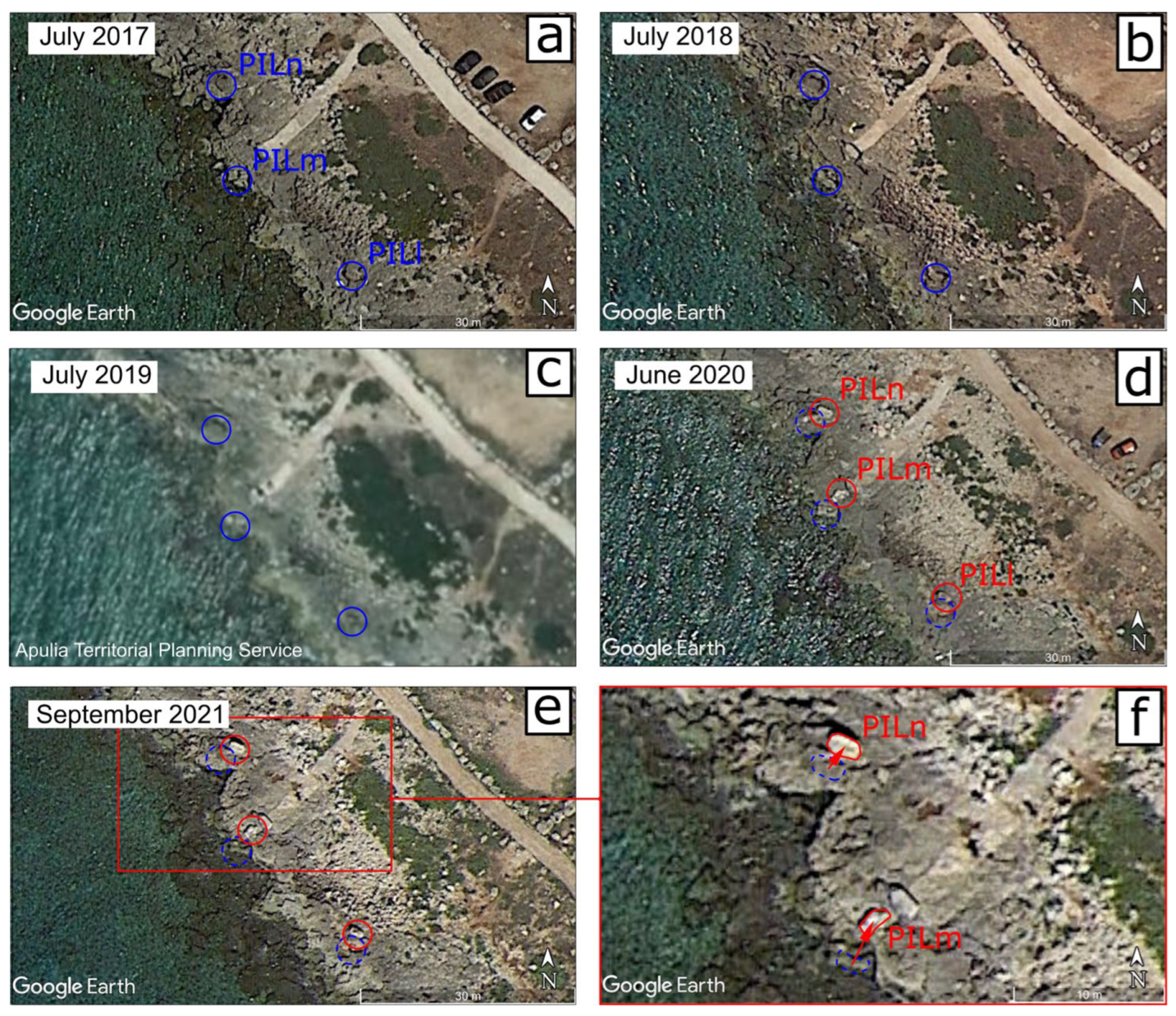
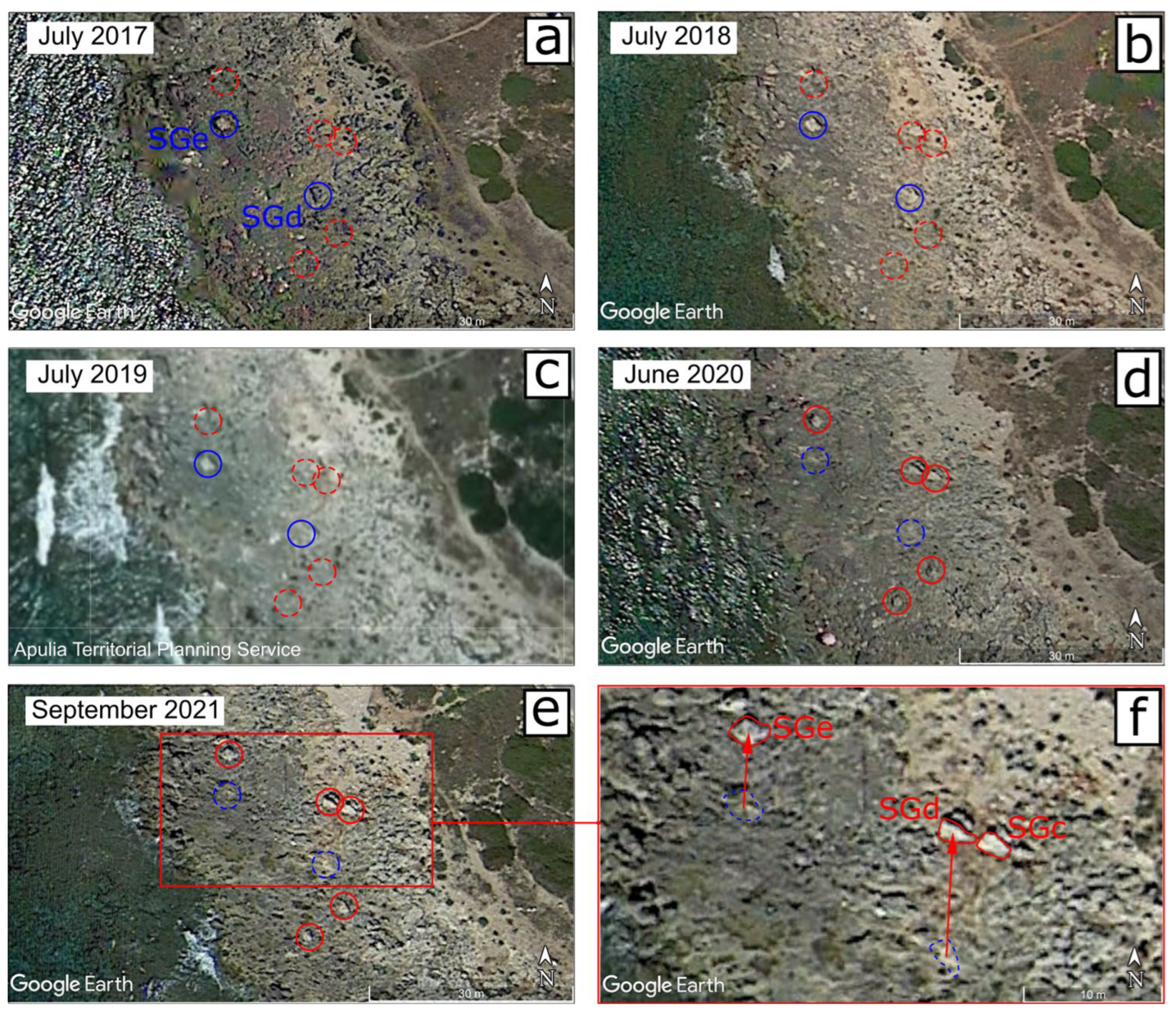
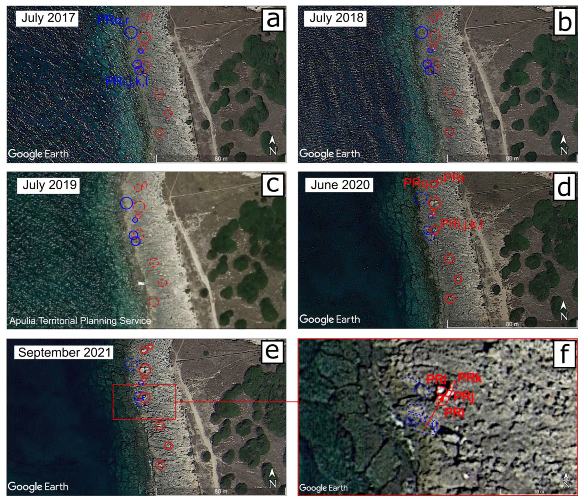
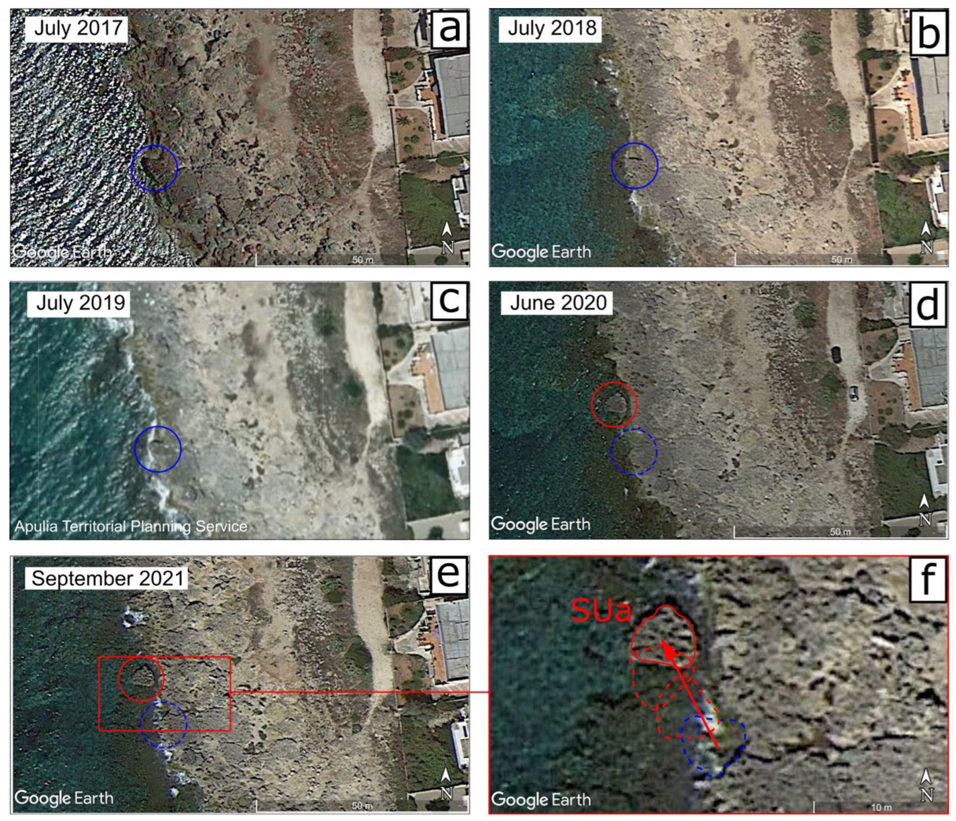
Appendix A
The data of the detected displaced boulders retrieved from remote sensing resources (see
Section 2 and
Section 3) together with morphometric features determined by on-site investigation are reported below (
Table A1,
Table A2,
Table A3,
Table A4,
Table A5,
Table A6,
Table A7 and
Table A8). Geographical coordinates and TD were taken from the September 2021 GE image. In the course of the field survey, the inclination to the horizontal position of the boulders
I and the dimensions of their axes (
af, major;
bf, middle;
cf, minor) were measured and the lithology (Li) of the boulders (which, in turn, allows us to determine ρ
s) established.
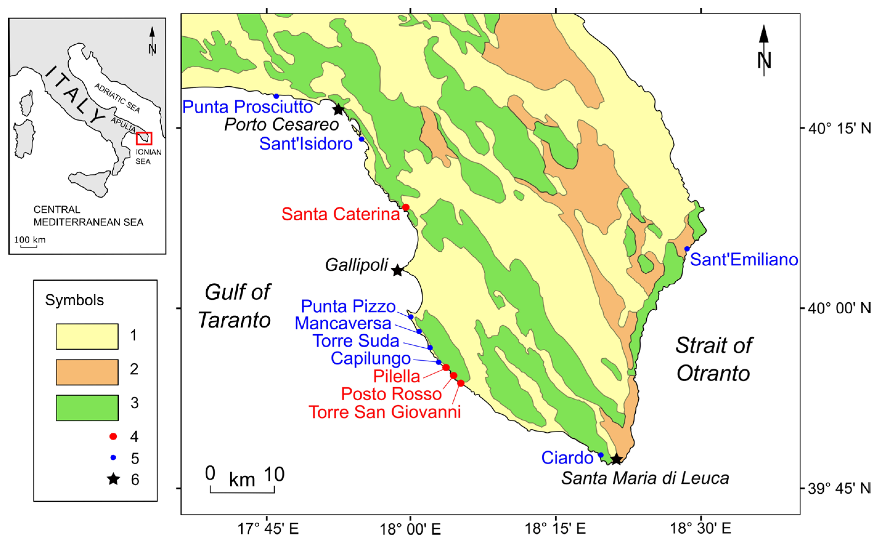
The PTS refers to some physical conditions (scenario) of the boulder before the displacement. The boulder can be isolated (sub-aerial, SA, or submerged, SB), laterally limited by joints (joint-bounded, JB), or located at the cliff edge (CE) [
1,
71]. These scenarios determine the possible three MTs (saltation/lifting, sliding, and overturning/rolling) during boulder displacement. SA and SB boulders can be lifted, slid, or rolled by the water flow; due to the movement constraints, JB boulders can only be lifted, while CE boulders can be lifted or rolled [
54,
56].
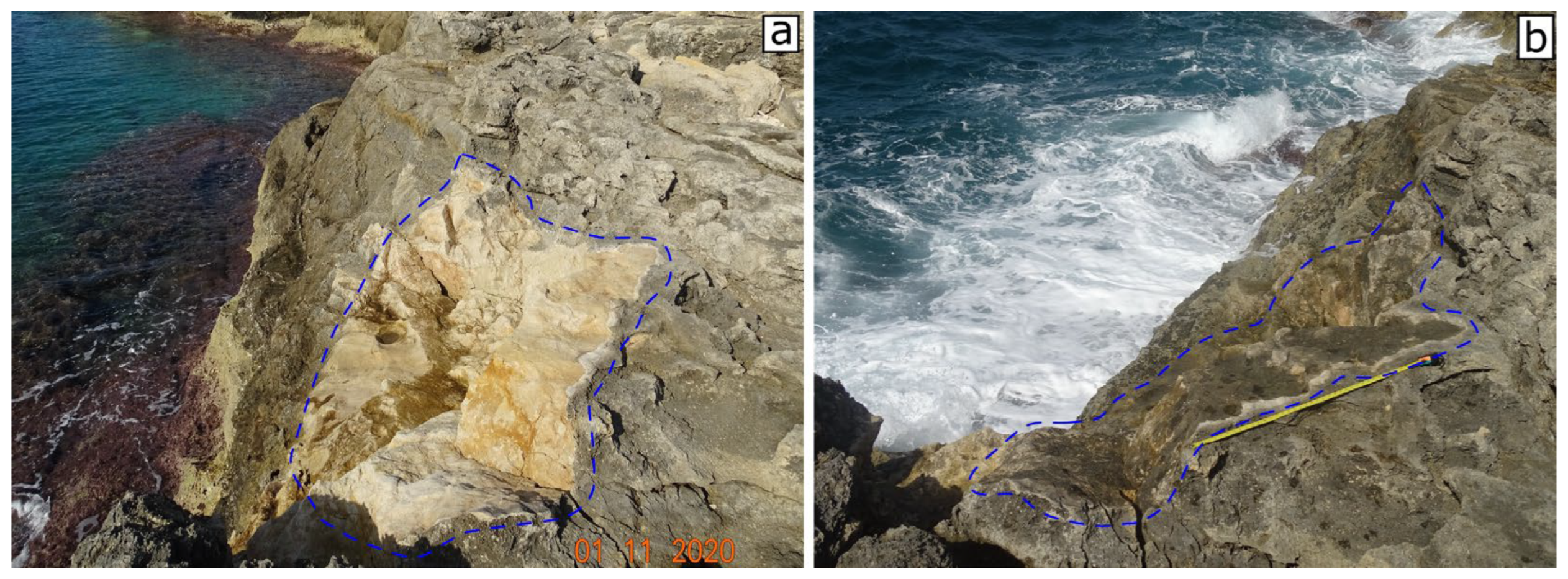
Figure A1 shows the socket left on the parent rock by the SCa boulder (
Section 3.1). The socket was ephemeral, so that a few years after its formation, it has become almost indistinguishable from its rock parent (
Figure A1a,b). The pre-transport setting of this boulder is “cliff edge” (CE) (see ref. [
56]). All the other boulder detected in the present work are “sub-aerial” (SA) or “submerged” (SB) (see
Table A2,
Table A4,
Table A6 and
Table A8).
Figure A1.
Santa Caterina site; the socket left by the SCa boulder (2.5 m over the sea level); (
a) after about 1 year from the detachment (the image was taken 1 November 2020), the rock surface is fresh and not weathered; (
b) after about 4 years from the detachment (the image was taken 22 September 2023, with 1 m long tape measure for scale), the rock surface is almost indistinguishable from the parent rock (see
Figure 2d,e).
The post-transport position of SCa in unknown (
Table A1). It was not recognized from GE images or in the field, and probably, SCa fell into the sea after detaching from its initial position.
Table A1.
Initial (pre-displacement) and final (post-displacement) geographical coordinates of the storm-displaced boulders at Santa Caterina coast; ind., indeterminable; A.I., annual interval in which the displacement occurred (see
Table 3).
Table A1.
Initial (pre-displacement) and final (post-displacement) geographical coordinates of the storm-displaced boulders at Santa Caterina coast; ind., indeterminable; A.I., annual interval in which the displacement occurred (see
Table 3).
| | Initial Position | Final Position | |
|---|
| ID | Latitude | Longitude | Latitude | Longitude | A.I. |
|---|
| SCa | 40°08′17.09″ N | 17°59′19.21″ E | ind. | ind. | 3 |
| SCb | 40°08′18.36″ N | 17°59′18.47″ E | 40°08′19.03″ N | 17°59′18.85″ E | 3 |
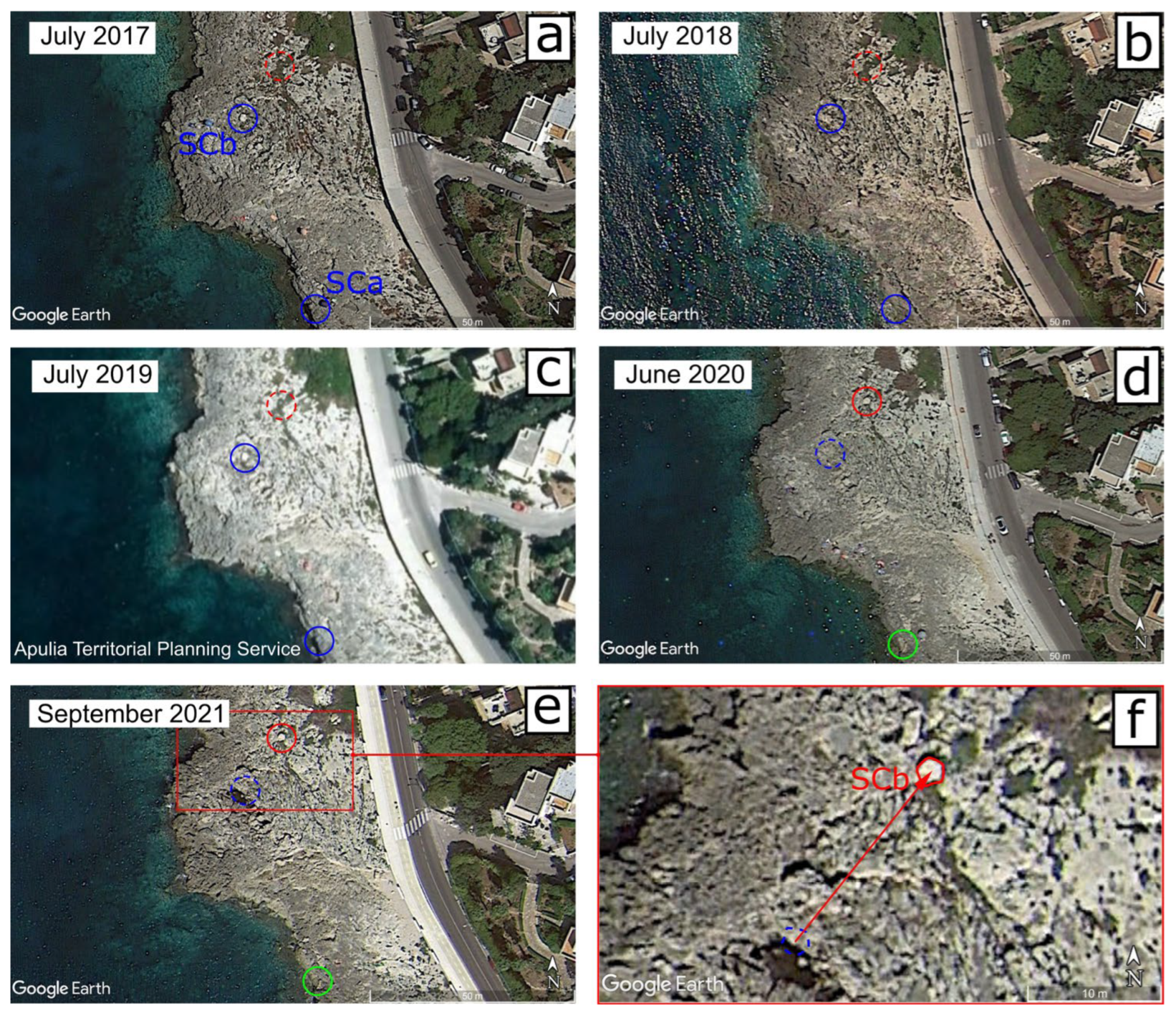
Differently from the socket of SCa, due to the different distance to the coastal cliff (
Table A2), the surface of the SCb boulder is still fresh and unaltered (
Figure A2). Moreover, since SCb lies in a shrub vegetation area, it is easily recognizable in remote sensing images (
Figure 2d,e).
Figure A2.
Santa Caterina site; the SCb boulder after the displacement occurred between July 2019 and September 2020 (the image was taken 22 September 2023, with 1 m long tape measure for scale). The whitish surface of SCb is uncovered by lichen and therefore still easily detectable in the field as well as by remote sensing images (see
Section 3.1).
Table A2.
Main features of the storm-displaced boulders at Santa Caterina coast; major and middle axes measured on GE remote sensing imagery:
ar and
br (in m); dimensions of the axes taken in the field:
af,
bf, and
cf (in m); inclination on the ground
I; initial distances from the coastline
xi; final distances from the coastline
xf (in m). TD, transport distance (in m); Li, lithology: C, calcarenite, L, limestone; Sh, shape: O, oblate (
b/
a > 0.6,
c/
b < 0.6); E, equant (
b/
a > 0.6,
c/
b > 0.6); B, bladed (
b/
a < 0.6,
c/
b < 0.6); P, prolate (
b/
a < 0.6,
c/
b > 0.6). FI, flatness index; PTS, pre-transport setting: JB, joint-bounded; SA, sub-aerial; SB, submerged; CE, cliff edge. MT, movement type: ST, saltation; SL, sliding; OV, overturning. ind., indeterminable. Note: Abbreviations are the same for
Table A4,
Table A6 and
Table A8.
| ID | ar | br | af | bf | cf | I | xi | xf | TD | Li | Sh | FI | PTS | MT |
|---|
| SCa | 3.3 | 1.2 | - | - | - | - | 0.8 | ind. | - | C | - | - | CE | - |
| SCb | 1.8 | 1.5 | 1.8 | 1.6 | 0.7 | 5° | 18.8 | 21.6 | 15.4 | C | O | 2.5 | SA | OV |
Table A3.
Initial (pre-displacement) and final (post-displacement) geographical coordinates of the storm-displaced boulders at the Pilella coast. Note: See caption of
Table A1 for abbreviations.
Table A3.
Initial (pre-displacement) and final (post-displacement) geographical coordinates of the storm-displaced boulders at the Pilella coast. Note: See caption of
Table A1 for abbreviations.
| | Initial Position | Final Position | |
|---|
| ID | Latitude | Longitude | Latitude | Longitude | A.I. |
|---|
| PILa | 39°55′22.66″ N | 18°03′35.76″ E | 39°55′22.72″ N | 18°03′35.80″ E | 3 |
| PILb | 39°55′22.60″ N | 18°03′35.42″ E | 39°55′22.68″ N | 18°03′35.51″ E | 3 |
| PILc | 39°55′22.27″ N | 18°03′34.62″ E | 39°55′22.35″ N | 18°03′34.66″ E | 3 |
| PILd | 39°55′22.24″ N | 18°03′34.49″ E | 39°55′22.33″ N | 18°03′34.50″ E | 3 |
| PILe | ind. | ind. | 39°55′23.54″ N | 18°03′32.43″ E | 3 |
| PILf | 39°55′23.83″ N | 18°03′31.60″ E | 39°55′23.88″ N | 18°03′31.63″ E | 3 |
| PILg | 39°55′23.97″ N | 18°03′31.61″ E | 39°55′24.11″ N | 18°03′31.72″ E | 3 |
| PILh | ind. | ind. | 39°55′24.08″ N | 18°03′30.58″ E | 3 |
| PILi | 39°55′24.39″ N | 18°03′31.08″ E | 39°55′24.49″ N | 18°03′31.12″ E | 3 |
| PILj | 39°55′25.09″ N | 18°03′27.70″ E | 39°55′25.10″ N | 18°03′27.78″ E | 3 |
| PILk | 39°55′25.38″ N | 18°03′27.86″ E | ind. | ind. | 3 |
| PILl | 39°55′26.41″ N | 18°03′27.20″ E | 39°55′26.49″ N | 18°03′27.26″ E | 3 |
| PILm | 39°55′26.86″ N | 18°03′26.56″ E | 39°55′26.96″ N | 18°03′26.64″ E | 3 |
| PILn | 39°55′27.29″ N | 18°03′26.47″ E | 39°55′27.32″ N | 18°03′26.54″ E | 3 |
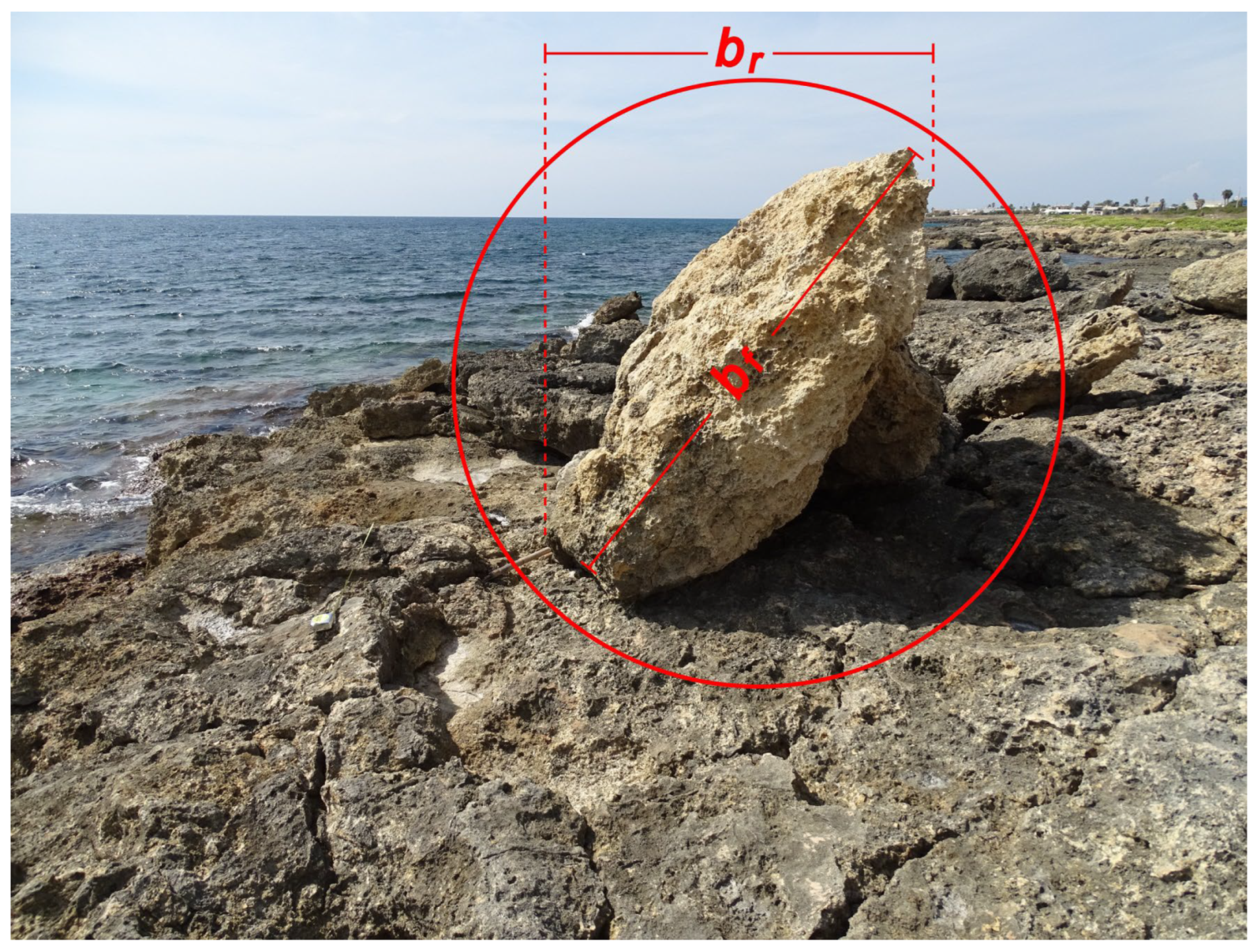
Several displaced boulders show a high value of
I. As an example, the PILn boulder (
Figure A3) is inclined of about 55° with respect to the ground (
Table A4). Such an arrangement can cause the underestimation of the horizontal dimensions of the boulders from remote sensing imagery (
Section 3).
Figure A3.
Pilella site; the PILn boulder lies on a smaller boulder and forms an angle of about 55° with respect to the ground. Note the difference in length between
br and
bf (see the caption of
Table A2 for symbols).
Figure A3.
Pilella site; the PILn boulder lies on a smaller boulder and forms an angle of about 55° with respect to the ground. Note the difference in length between
br and
bf (see the caption of
Table A2 for symbols).
As mentioned in
Section 2.3, after estimating the center point of the boulders at the initial and final positions, several TDs were verified onsite by means of a measuring tape. At the Pilella coast, the measurements taken almost never differed more than 5% from those detected in the remote sensing images (see also
Appendix B in ref. [
9]). As an example, for the PILm boulder, 3.4 m was measured in the field against 3.7 m in the image.
Table A4.
Main features of the storm-displaced boulders at the Pilella coast. Note: See caption of
Table A2 for abbreviations.
Table A4.
Main features of the storm-displaced boulders at the Pilella coast. Note: See caption of
Table A2 for abbreviations.
| ID | ar | br | af | bf | cf | I | xi | xf | TD | Li | Sh | FI | PTS | MT |
|---|
| PILa | 1.6 | 0.9 | 1.6 | 1.0 | 0.5 | 0–5° | 10.8 | 12.4 | 3.6 | C | O | 2.6 | SA | OV |
| PILb | 2.0 | 1.0 | 1.8 | 1.0 | 0.4 | 0–5° | 9.4 | 10.5 | 4.1 | C | B | 3.5 | SA | OV |
| PILc | 1.5 | 1.0 | 1.5 | 0.9 | 0.4 | ~20° | 12.4 | 14.7 | 2.5 | C | B | 3 | SA | OV |
| PILd | 2.0 | 1.2 | 1.9 | 1.0 | 0.6 | 0–5° | 13.6 | 15.6 | 2.6 | C | B | 2.4 | SA | OV |
| PILe | 2.3 | 1.6 | 2.5 | 1.5 | 0.3 | ~15° | ind. | 13.2 | - | C | O | 6.7 | SB | ST,OV |
| PILf | 2.2 | 1.5 | 2.4 | 1.2 | 0.5 | ~60° | 10.9 | 12.5 | 1.5 | C | B | 3.6 | SA | SL |
| PILg | 1.7 | 1.4 | 1.5 | 1.3 | 0.6 | ~10° | 10.6 | 15.5 | 4.8 | C | O | 2.3 | SA | OV |
| PILh | 2.2 | 1.0 | 1.9 | 1.0 | 0.5 | 5° | ind. | 3.9 | - | L | B | 2.9 | SB | ind. |
| PILi | 1.9 | 1.1 | 2.2 | 1.1 | 0.4 | 5° | 18.8 | 20.4 | 2.6 | C | B | 4.1 | SA | ST,OV |
| PILj | 3.1 | 1.9 | 3.0 | 1.8 | 0.6 | 5° | 0.7 | 1.9 | 1.6 | C | O | 4 | SB | SL |
| PILk | 2.0 | 1.4 | - | - | - | - | 6.9 | ind. | - | - | - | - | SA | - |
| PILl | 2.0 | 1.1 | 2.1 | 1.1 | 0.8 | 0–5° | 7.0 | 8.9 | 3.3 | L | P | 2 | SA | OV |
| PILm | 2.1 | 1.1 | 2.0 | 1.0 | 0.4 | 0–5° | 1.1 | 3.7 | 3.2 | C | B | 3.7 | SA | OV |
| PILn | 2.2 | 1.2 | 2.1 | 1.8 | 0.4 | ~55° | 4.4 | 6.2 | 1.9 | C | O | 4.9 | SA | OV |
Most of the boulders examined at Pilella clearly show fresh and not weathered surfaces, while the surfaces covered by lichen and with karst dissolution features are in contact with the ground. They must be considered as SA overturned boulders.
The initial position of both the PILe and PILh boulders was not detected in the time series remote sensing images (
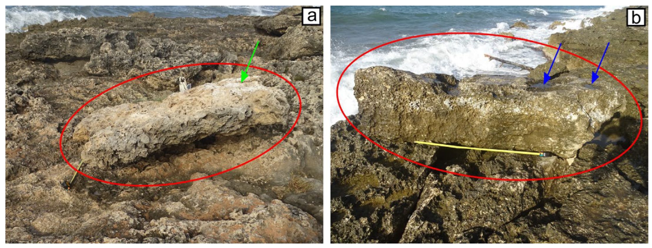
Table A4). At its final position, the upper surface of PILe is whitish and is covered by decaying marine plants (
Figure A4a). This suggests that it was below sea level before the transport. PILh is currently just over the edge of the cliff, and it presents some solution pans over its upper surface (
Figure A4b). Before the displacement, it was roughly at the sea level. For the PILf and PILj boulders, some tracks referable as drag marks were observed along their trajectory, and consequently, their type of movement is considered SL (
Table A4). For the remaining boulders, no elements useful to define with good confidence the MT were identified.
Figure A4.
Pilella site; (a) the PILe boulder (green arrow indicates decaying marine plants); (b) the PILh boulder (blue arrows indicate solution pans).
Figure A4.
Pilella site; (a) the PILe boulder (green arrow indicates decaying marine plants); (b) the PILh boulder (blue arrows indicate solution pans).
Table A5.
Initial (pre-displacement) and final (post-displacement) geographical coordinates of the storm-displaced boulders at the Posto Rosso coast. Note: See caption of
Table A1 for abbreviations.
Table A5.
Initial (pre-displacement) and final (post-displacement) geographical coordinates of the storm-displaced boulders at the Posto Rosso coast. Note: See caption of
Table A1 for abbreviations.
| | Initial Position | Final Position | |
|---|
| ID | Latitude | Longitude | Latitude | Longitude | A.I. |
|---|
| ROa | 30°54′45.53″ N | 18°04′20.88″ E | 30°54′47.70″ N | 18°04′20.99″ E | 3 |
| ROb | 30°54′46.19″ N | 18°04′20.51″ E | 30°54′46.21″ N | 18°04′20.55″ E | 3 |
| ROc | 30°54′46.87″ N | 18°04′20.58″ E | 30°54′46.90″ N | 18°04′20.69″ E | 3 |
| ROd | 30°54′47.88″ N | 18°04′18.76″ E | 30°54′48.03″ N | 18°04′18.79″ E | 3 |
| ROe | ind. | ind. | 30°54′48.30″ N | 18°04′17.88″ E | 3 |
| ROf | 30°54′48.40″ N | 18°04′17.90″ E | 30°54′48.45″ N | 18°04′17.96″ E | 3 |
| ROg | ind. | ind. | 30°54′48.39″ N | 18°04′17.57″ E | 3 |
| ROh | ind. | ind. | 30°54′48.43″ N | 18°04′17.54″ E | 3 |
| ROi | 30°54′48.38″ N | 18°04′17.34″ E | 30°54′48.44″ N | 18°04′17.36″ E | 3 |
| ROj | 30°54′48.40″ N | 18°04′17.44″ E | 30°54′48.51″ N | 18°04′17.47″ E | 3 |
| ROk | 30°54′48.45″ N | 18°04′17.59″ E | 30°54′48.52″ N | 18°04′17.37″ E | 3 |
| ROl | ind. | ind. | 30°54′48.79″ N | 18°04′17.15″ E | 4 |
| ROm | 30°54′49.29″ N | 18°04′16.85″ E | 30°54′49.40″ N | 18°04′16.95″ E | 3 |
| ROn | 30°54′49.02″ N | 18°04′15.97″ E | 30°54′48.48″ N | 18°04′16.41″ E | 3 |
| ROo | ind. | ind. | 30°54′49.68″ N | 18°04′16.38″ E | 3 |
| ROp | ind. | ind. | 30°54′49.71″ N | 18°04′16.43″ E | 3 |
Many coarse boulders were detected at the Posto Rosso site (
Section 3.1,
Table A6). The ROa boulder was detached and overturned (
Figure A5a). The boulder ROl also appears to have been overturned (
Figure A5b). The ROn boulder, despite its large size, was transported for 17.5 m due to the water flow (
Figure A5c,d). This measure, taken using a measuring tape, differs from the one detected in the remote sensing image by less than 0.5 m (
Table A6). In
Figure A5c, one phase of estimating the position of the geometric center of the boulder before the movement can be observed. Again, ROn is not overturned, and no drag marks are observed over the platform surface. Thus, it appears to have undergone a saltation movement.
Figure A5.
Posto Rosso site; (
a) the overturned ROa boulder and (in the foreground) its socket (with 1 m long tape measure for scale); (
b) the geomorphological arrangement of ROl boulder that was displaced during the 2020–2021 CW season (see
Section 3.1); (
c) the socket of the ROn boulder; (
d) the ROn boulder was detached from its initial position and displaced 17–17.5 m inland (see text).
Table A6.
Main features of the storm-displaced boulders at the Posto Rosso coast. Note: See caption of
Table A2 for abbreviations.
Table A6.
Main features of the storm-displaced boulders at the Posto Rosso coast. Note: See caption of
Table A2 for abbreviations.
| ID | ar | br | af | bf | cf | I | xi | xf | TD | Li | Sh | FI | PTS | MT |
|---|
| ROa | 2.7 | 1.4 | 2.7 | 1.3 | 0.8 | 0–5° | 12.3 | 18.5 | 5.8 | C | P | 2.5 | SA | OV |
| ROb | 2.8 | 1.3 | 2.9 | 1.4 | 0.6 | 0–5° | 5.7 | 6.7 | 1.9 | C | B | 3.6 | SA | SL |
| ROc | 1.6 | 1.3 | 1.7 | 1.4 | 0.5 | 0–5° | 15.9 | 18.2 | 2.5 | C | O | 3.1 | SA | ST,OV |
| ROd | 2.5 | 1.9 | 2.4 | 1.5 | 0.7 | ~20° | 10.4 | 14.7 | 4.5 | C | O | 2.8 | SA | OV |
| ROe | 2.1 | 1.6 | 2.3 | 1.6 | 0.5 | 0–5° | ind. | 11.2 | - | C | O | 3.9 | SB | ind. |
| ROf | 1.8 | 1.4 | 1.7 | 1.4 | 0.7 | 0–5° | 13.6 | 15.8 | 2.1 | C | O | 2.2 | SA | ST,OV |
| ROg | 1.5 | 0.9 | 1.3 | 0.9 | 0.4 | ~25° | ind. | 14.6 | - | C | B | 2.7 | SB | ST |
| ROh | 1.6 | 0.9 | 1.7 | 0.9 | 0.7 | 0–5° | ind. | 14.4 | - | C | P | 1.8 | SB | ST,OV |
| ROi | 2.8 | 1.3 | 2.7 | 1.4 | 0.7 | ~10° | 11.1 | 12.6 | 1.9 | C | B | 2.9 | SA | ST,OV |
| ROj | 2.6 | 1.5 | 2.4 | 1.7 | 0.8 | ~20° | 14.4 | 16.7 | 3.1 | C | B | 2.6 | SA | OV |
| ROk | 1.7 | 1.2 | 1.7 | 1.3 | 0.7 | ~15° | 14.2 | 16.1 | 2.1 | C | O | 2.1 | SA | OV |
| ROl | 1.8 | 1.3 | 1.9 | 1.2 | 0.3 | ~20° | ind. | 9.3 | - | C | O | 5.2 | SB | OV |
| ROm | 1.5 | 0.8 | 1.4 | 0.8 | 0.5 | 0–5° | 20.3 | 25.2 | 4.8 | C | P | 2.2 | SA | ST,OV |
| ROn | 3.1 | 1.8 | 2.8 | 2.1 | 0.5 | ~20° | 4.2 | 20.7 | 17.1 | C | O | 4.9 | SA | ST |
| ROo | 1.3 | 0.9 | 1.4 | 0.9 | 0.5 | ~10° | ind. | 25.3 | - | C | B | 2.3 | SB | ST,OV |
| ROp | 1.5 | 0.8 | 1.7 | 1.1 | 0.5 | ~25° | ind. | 26.4 | - | C | O | 2.8 | SB | ST,OV |
Table A7.
Initial (pre-displacement) and final (post-displacement) geographical coordinates of the storm-displaced boulders at the Torre San Giovanni coast. Note: See caption of
Table A1 for abbreviations.
Table A7.
Initial (pre-displacement) and final (post-displacement) geographical coordinates of the storm-displaced boulders at the Torre San Giovanni coast. Note: See caption of
Table A1 for abbreviations.
| | Initial Position | Final Position | |
|---|
| ID | Latitude | Longitude | Latitude | Longitude | A.I. |
|---|
| SGa | ind. | ind. | 39°54′03.86″ N | 18°05′09.25″ E | 3 |
| SGb | ind. | ind. | 39°54′03.99″ N | 18°05′09.47″ E | 3 |
| SGc | ind. | ind. | 39°54′04.46″ N | 18°05′09.50″ E | 3 |
| SGd | 39°54′04.18″ N | 18°05′09.34″ E | 39°54′04.49″ N | 18°05′09.38″ E | 3 |
| SGe | 39°54′04.52″ N | 18°05′08.72″ E | 39°54′04.73″ N | 18°05′08.76″ E | 3 |
| SGf | 39°54′05.57″ N | 18°05′08.45″ E | 39°54′05.61″ N | 18°05′08.53″ E | 3 |
Several of the displaced boulders are rather flat (e.g., PILe and SGd; see
Table A4 and
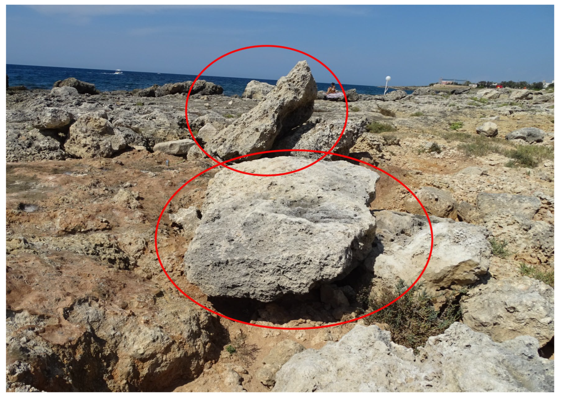
Table A8, respectively). The flat SGd boulder (FI = 6;
Figure A6) was transported almost 10 m from an initial position more than 20 m away from the coastline.
For the SGd, SGe, and SGf boulders, the TD was verified onsite. Again, these measures do not differ by more than 5% from those detected in the remote sensing images.
Figure A6.
Torre San Giovanni site; SGc (in the foreground) and SGd boulders. As a result of the water flow transport, they formed two imbricated clusters together with other small boulders.
Figure A6.
Torre San Giovanni site; SGc (in the foreground) and SGd boulders. As a result of the water flow transport, they formed two imbricated clusters together with other small boulders.
Table A8.
Main features of the storm-displaced boulders at the Torre San Giovanni coast. Note: See caption of
Table A2 for abbreviations.
Table A8.
Main features of the storm-displaced boulders at the Torre San Giovanni coast. Note: See caption of
Table A2 for abbreviations.
| ID | ar | br | af | bf | cf | I | xi | xf | TD | Li | Sh | FI | PTS | MT |
|---|
| SGa | 1.5 | 0.9 | 1.4 | 1.1 | 0.4 | 0–5° | ind. | 14.9 | - | C | O | 3.1 | SB | ST,OV |
| SGb | 1.8 | 1.1 | 1.8 | 1.0 | 0.3 | 0–5° | ind. | 22.3 | - | C | B | 4.7 | SB | ST,OV |
| SGc | 1.9 | 1.1 | 1.8 | 1.2 | 0.3 | 0–5° | ind. | 31.4 | - | C | O | 5 | SB | ST,OV |
| SGd | 2.1 | 0.9 | 2.3 | 1.3 | 0.3 | ~45° | 22.8 | 28.6 | 9.5 | C | B | 6 | SA | ST,OV |
| SGe | 2.4 | 1.7 | 2.2 | 1.7 | 0.7 | 0–5° | 13.8 | 18.2 | 6.5 | C | O | 2.8 | SA | ST,OV |
| SGf | 1.6 | 0.8 | 1.5 | 1.2 | 0.6 | ~30° | 10.4 | 11.7 | 2.4 | C | O | 2.2 | SA | OV |
When both the initial and final positions of the detected boulders were established, the transport distance was calculated (
Section 4.1 and
Section 4.2). In
Table A9 and
Table A10, a list of these 84 boulders is given.
Table A9.
Displaced boulders detected in this study for which TD was calculated and whose position changed between July 2019 and June 2020.
Table A9.
Displaced boulders detected in this study for which TD was calculated and whose position changed between July 2019 and June 2020.
| Site | Boulder ID 1 |
|---|
| Santa Caterina | SCb |
| Pilella | PILa, PILb, PILc, PILd, PILf, PILg, PILi, PILj, PILl, PILm, PILn |
| Posto Rosso | ROa, ROb, ROc, ROd, ROf, ROi, ROj, ROk, ROm, ROn |
| Torre San Giovanni | SGd, SGe, SGf |
Table A10.
Displaced boulders detected by [
9] whose position results changed between July 2019 and June 2020 and for which TD was calculated.
Table A10.
Displaced boulders detected by [
9] whose position results changed between July 2019 and June 2020 and for which TD was calculated.
| Site | Boulder ID 1 |
|---|
| Punta Prosciutto | PRa, PRb, PRc, PRd, PRe, PRf, PRi, PRj, PRk, PRl, PRm, PRq, PRr |
| Sant’Isidoro | SIf, SIg |
| Punta Pizzo | PIa, PIb, PIc, PId, PIe, PIg, PIh, PIj, PIm, PIn, PIo, PIp, PIr |
| Mancaversa | MAa, MAb, MAc, MAf, MAg, MAh, MAi, MAj, MAk, MAl, MAm, MAn |
| Torre Suda | SUa, SUe, SUf, SUh, SUi, SUj, SUk, SUl, SUn |
| Capilungo | CAa, CAb, CAc, CAd, CAe, CAf |
| Ciardo | CIa, CIb, CIc, CId |
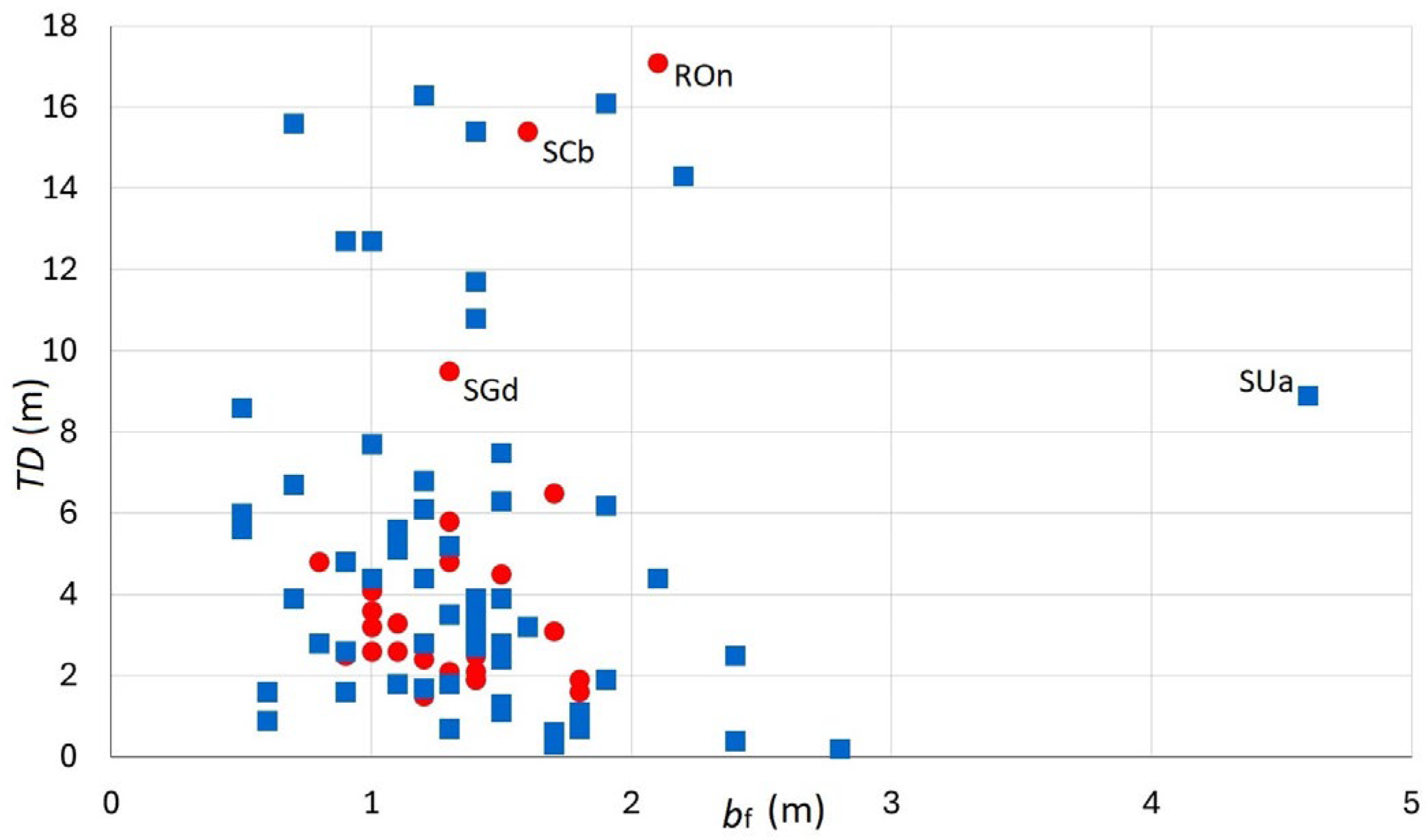
Based on the above sets of data, it can be deduced that more than 65% of medium-to-coarse boulders were moved less than 5 m, while less than 15% were moved more than 10 m, including the SCb and ROn boulders (
Figure A7;
Table A1,
Table A2,
Table A5 and
Table A6 for morphometric data). This result agrees with those of other studies performed with different methods on Mediterranean coasts [
72,
73].
Figure A7.
Transport distance (TD) vs. middle axis measured in the field (
bf). Red circles, boulders detected in the present study; blue squares, boulders detected in the previous study [
9].
Figure A7.
Transport distance (TD) vs. middle axis measured in the field (
bf). Red circles, boulders detected in the present study; blue squares, boulders detected in the previous study [
9].
As reported in
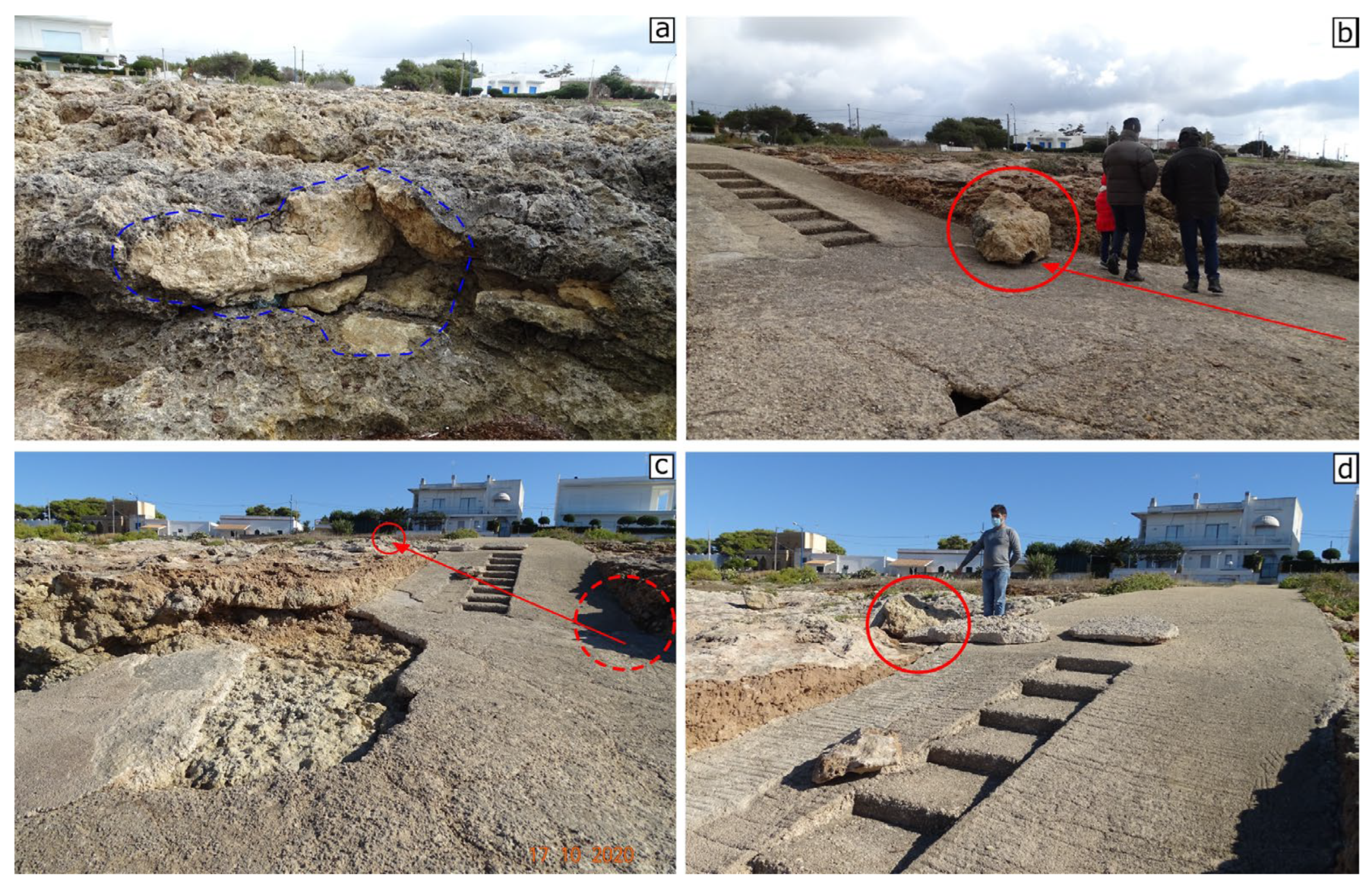
Section 3, two boulders underwent two displacements during 2017–2021. In the case of the SUi boulder (
Section 3.2), this singular mobility can be due to a slipway ramp that channels the water flows (
Figure A8).
Figure A8.
Torre Suda site; (a) the socket of the SUi boulder (image taken the 23 February 2019); (b) SUi boulder lying on a slipway ramp after the first movement (image taken 23 February 2019); (c,d) SUi boulder displaced from the ramp due to the second movement (images taken 17 October 2020).
Figure A8.
Torre Suda site; (a) the socket of the SUi boulder (image taken the 23 February 2019); (b) SUi boulder lying on a slipway ramp after the first movement (image taken 23 February 2019); (c,d) SUi boulder displaced from the ramp due to the second movement (images taken 17 October 2020).
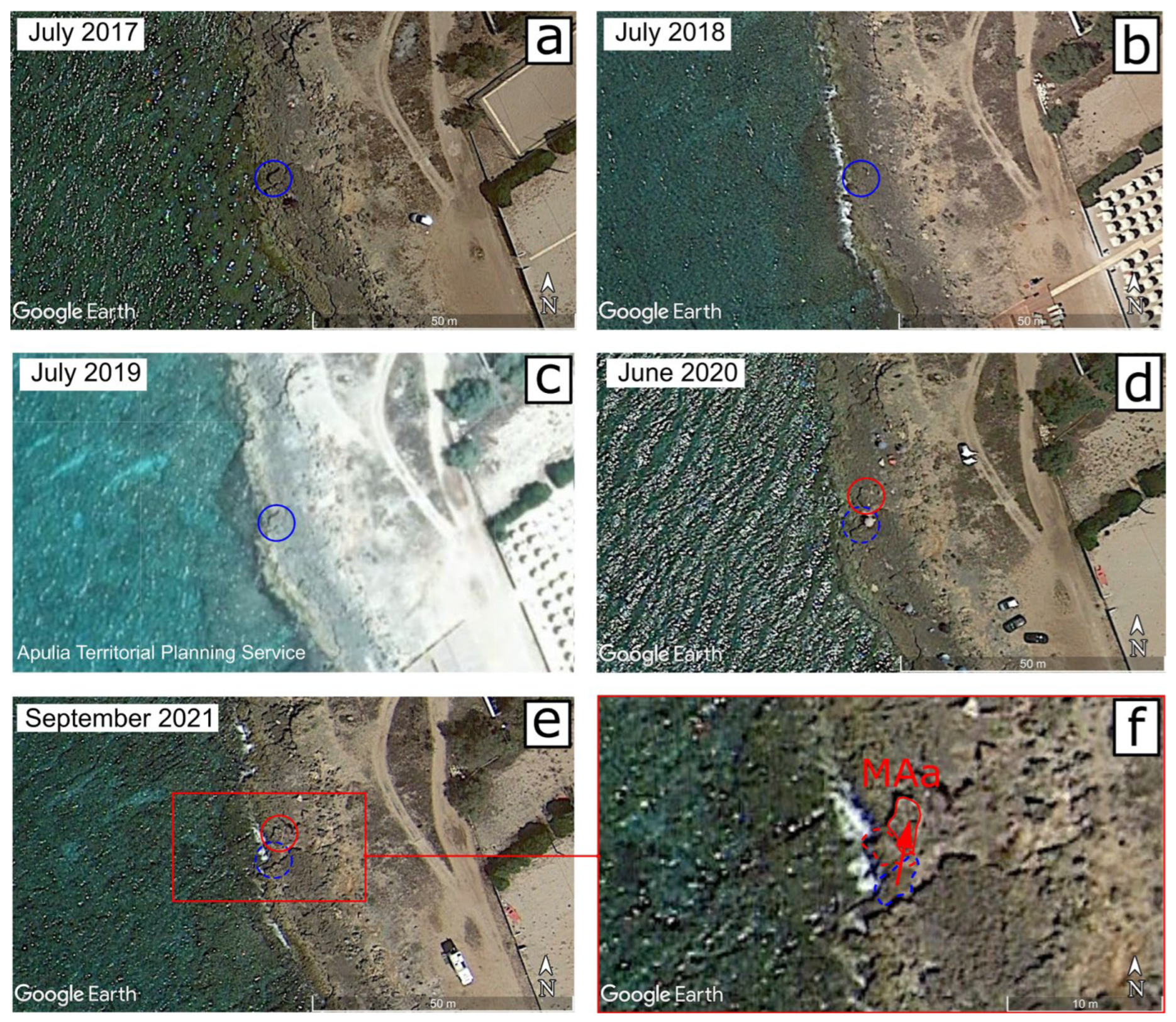
The PTS of the MAa boulder was considered as joint-bounded (JB) in the previous work [
9]. It was detached from the parent rock along a vertical joint system, leaving a small step on the ground surface (
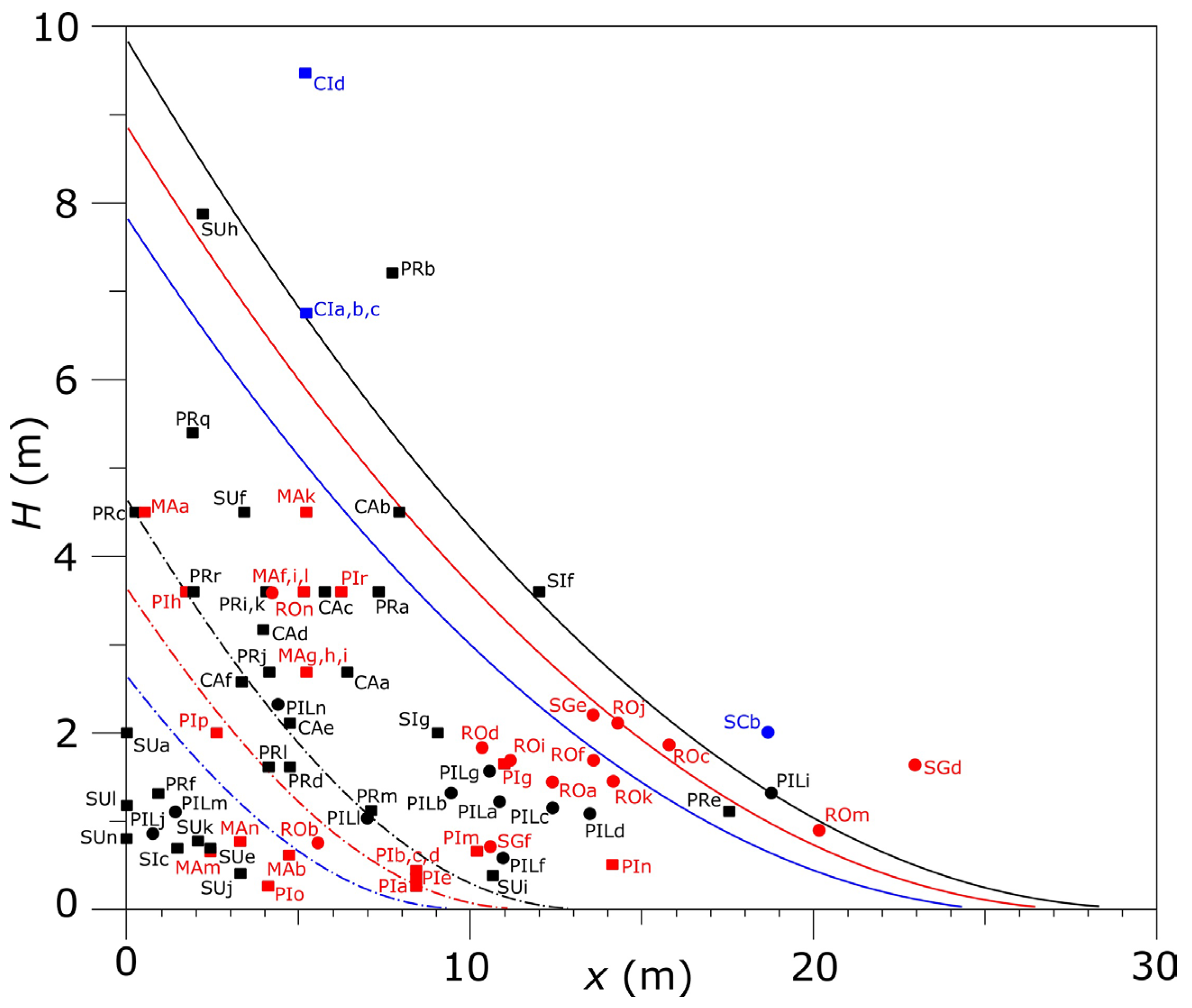
Figure A9). In any case, MAa did not jump over the step, as it was moved in opposite direction. The boulder could therefore be considered SA. Since the slope angle (θ) is zero, the minimum wave height calculated by the Equations (A4) and (A7) (
Appendix B) is the same (
Hm = 4.5 m; see
Figure 10).
Figure A9.
Mancaversa site; the MAa boulder lying about 4.5 m from its initial position (in the foreground); rock joints are indicated by green arrows (see text).
Figure A9.
Mancaversa site; the MAa boulder lying about 4.5 m from its initial position (in the foreground); rock joints are indicated by green arrows (see text).
For the MAa boulder, the TD was verified onsite. Again, this measure does not differ by more than 5% from that detected in the remote sensing image.
Appendix B
As mentioned in
Section 2.3, the windstorm characteristics (duration
R, length of the fetch over the sea surface
F, fetch direction
D, and wind speed
U) determined by the forecast map archive of the BOLAM-MOLOCH model [
53] were used to calculate the spectral peak wave height from the similarity relation equations [
74,
75]. They relate
T (wave period),
H0, and
R to the wind speed at 10 m height offshore
U and to the fetch over the sea
F:
where
g is the gravity acceleration. This procedure has already been used in previous works [
9].
The duration
R of stability of wind conditions, estimated from the wind maps, was used as a limiting factor to calculate an effective fetch
F for Equations (A1) and (A2) whenever the actual geometric fetch appears to be longer. It must be noted that
H0 is nearly equivalent to the significant wave height [
76,
77].
Data of wind gauge stations placed along the coast (
Figure 1) have been used to infer the nearshore wind conditions during storms presumed to be responsible for changes in boulder position. Due to the incompleteness and inhomogeneity of the datasets, these conditions can be only partially defined. The Santa Maria di Leuca and Gallipoli stations are managed by the Apulia Civil Protection that publishes comprehensive annual reports (named
Annali Idrologici, Hydrological Annals) [
78,
79,
80,
81,
82]. These report the daily average and maximum together with four 30 min averages at four selected hours of the day (00, 06, 12, and 18). However, the Gallipoli station has been in operation only since November 2020. The Porto Cesareo station belongs to the Apulia Meteomarine Network (
SIMOP,
Sistema Informativo Meteo Oceanografico delle Coste Pugliesi, in Italian); its data are publicly available online and consist of 15 min measures of wind speed and direction [
83]. The Porto Cesareo station has been in operation since February 2019.
The displacement of boulders due to wave impact on the coast starts when the hydrodynamics forces exceed the resistance forces of net friction [
54,
55]. Nandasena et al. [
1,
71] and Nandasena [
56] elaborated a set of equations to calculate the minimum wave height (
Hm) required to set in motion and cause onshore transport of the boulders, depending on PTS and MT. For SA and SB boulders moved by saltation/lifting, sliding, and rolling,
Hm is as follows, respectively:
For JB boulders moved by saltation/lifting,
Hm is as follows:
For CE boulders moved by saltation/lifting and rolling,
Hm is as follows, respectively:
In the Equations (A4)–(A9):
b = b-axis length (m);
c = c-axis length (m); ρ
s = density of boulder (kg m
−3); ρ
w = density of seawater (kg m
−3); θ = bed slope angle (degrees); μ = coefficient of static friction along the ground surface; C
L = lift coefficient; C
D = drag coefficient. As is known, the values of the coefficients C
D and C
L are crucial in determining the reliability of the results [
61,
84,
85]. Their correct determination would require considering the influence of environmental factors like the substrate roughness and flow turbulence and performing hydrodynamic site-specific measurements. Considering that, in the present work, the use of the above equations is simply aimed at a comparison with the results of the previous work [
9], the values of 1.95 for C
D, 0.178 for C
L, and 0.7 for μ were used (see, e.g., refs. [
1,
9,
48,
86,
87]). Again, based on the local geology, the following values of density (ρ
s) were used: 1.8 kg m
−3 for calcarenite; 2.2 kg m
−3 for limestone.
To estimate the decrease in wave height over the shore, say the effective wave height
H impacting the boulder at the distance
x from the shoreline, the equation of Cox and Machemehl [
60] was used:
In Equation (A10): x = distance from the coastline (m); g = gravity acceleration; T was estimated by Equation (A1); the breaking wave height R was directly estimated as its minimum value H0 from Equation (A2); the average coastline height above the mean sea level Hc was corrected by the total sea level increase (storm surge + tide) Hs.
Appendix D
By using the storm power index (SPI) introduced by Dolan and Davis [
90], the intensity of the storms reported in
Table 2 can be calculated. SPI is defined as the “
storm’s duration times the square of maximum significant wave height” [
90]. A number of studies have shown a strong correlation between SPI and the wave impact on the coasts (see, e.g., [
91,
92,
93]). Considering that
H0 is nearly equivalent to the significant wave height [
76,
77], the storm intensities can be assessed as reported in
Figure A14.
Figure A14.
Storm power index (in m
2 h) of the storms in
Table 2. Annual intervals of
Table 3 are reported in the upper side.
Figure A14.
Storm power index (in m
2 h) of the storms in
Table 2. Annual intervals of
Table 3 are reported in the upper side.
Considering the obtained values of SPI, the quite different ability of the two most severe storms to determine geomorphological signatures in the study area is surprising. It can be guessed that the interplay between wind speed and length and duration in time of the fetch involved can determine a sort of threshold-like behavior between storms that do not cause massive changes (including Vaia) and the most intense one (Detlef). Some insights into the reasons for the different effects of the two storms on the studied coast were discussed in Delle Rose and Martano [
4] and Delle Rose et al. [
9].
As stated above (
Section 4.3), some boulders displaced during the interval 3 (
Table 3) could be caused by the storms that occurred between 24 November 2019 and 2 March 2020 (
Figure 10). Considering
Figure A14, the storm that occurred on 22 December 2019 (SPI about 580) seems to be the main suspect. However, considering that storm Vaia (SPI about 1570) was able to move only one of the detected boulders (
Section 3.2), this probability is rather low. On the other hand, the 3 December 2020 storm can be considered the most probable cause for the two displacements that occurred during the interval 4 (
Table 3).
The strong power of storm Detlef on the eastern coast of the Gulf of Taranto is supported also by the resulting damage [
17,
21]. Promenade walls were destroyed and breakwater blocks displaced toward the coastal roads. The most affected places were Porto Cesareo, Santa Caterina, and Gallipoli (
Figure 1). In the last town, several boats sunk, and numerous infrastructures along the seafront were destroyed. Differently, no damage was reported for the other considered storms.
A quantitative comparison with other phenomena of boulder displacements can help to better understand the work caused by storm Detlef on the studied coast. Several authors used the minimum flow velocity
V to set the boulders in motion [
1,
71] as a measure of the nearshore wave energy (see, e.g., [
48,
86,
94]). For the biggest displaced boulders herein considered,
V ranges from 2.7 to 8.1 m/s (
Table A12).
Table A12.
Minimum flow velocity (
V) (in m/s) required to set the boulders in motion;
af, bf, cf, x
i, and TD (in m).
V was computed with the equations of Nandasena et al. [
1,
71]. Note: See caption of
Table A2 for abbreviations.
Table A12.
Minimum flow velocity (
V) (in m/s) required to set the boulders in motion;
af, bf, cf, x
i, and TD (in m).
V was computed with the equations of Nandasena et al. [
1,
71]. Note: See caption of
Table A2 for abbreviations.
| Boulder ID | Size (af × bf × cf) | xi | TD | PTS | MT | V |
|---|
| PRq 1 | 2.7 × 1.4 × 0.4 | 1.9 | 11.7 | SA | ST | 5.9 |
| SIg 1 | 1.7 × 1.5 × 0.5 | 9 | 2.4 | SA | OV | 4.4 |
| SCb | 1.8 × 1.6 × 0.7 | 18.8 | 15.4 | SA | OV | 5.4 |
| PIh 1 | 3.1 × 2.2 × 0.4 | 1.7 | 14.3 | SA | ST | 5.9 |
| MAa 1 | 3.4 × 2.1 × 0.5 | 0.6 | 4.4 | SA | SL | 2.8 |
| SUa 1 | 5.4 × 4.6 × 1.9 | 0 | 8.9 | SB | SL | 4.4 |
| CAd 1 | 2.6 × 2.4 × 0.9 | 3.9 | 2.5 | SA | OV | 5.6 |
| PILj | 3.0 × 1.8 × 0.6 | 0.7 | 1.6 | SB | SL | 2.7 |
| ROd | 2.4 × 1.5 × 0.7 | 10.4 | 4.5 | SA | OV | 4.3 |
| ROn | 2.8 × 2.1 × 0.5 | 4.2 | 17.1 | SA | ST | 6.6 |
| SGe | 2.2 × 1.7 × 0.7 | 13.8 | 6.5 | SA | ST | 7.8 |
| CIc 1 | 2.2 × 1.4 × 0.5 | 5.2 | 3.3 | SA | ST | 8.1 |
Values of
V up to 14 m/s were calculated to explain boulder displacements due to inundation events driven by typhoons in the Asia-Pacific region [
39,
79,
94,
95,
96]. Instead, for the Mediterranean region,
V values up to 12 m/s are reported in the literature to displace SA or SB boulders by severe storms [
1,
48]. Therefore, the values in
Table A12 appear consistent (in terms of order of magnitude) with those found in the literature.
