Article

Vs30 Mapping of the Greater Montreal Region Using Multiple Data Sources

Department of Civil Engineering, McGill University, Montreal, QC H3A 0C3, Canada
*
Author to whom correspondence should be addressed.
Geosciences 2023, 13(9), 256; https://doi.org/10.3390/geosciences13090256
Submission received: 23 June 2023 / Revised: 14 August 2023 / Accepted: 18 August 2023 / Published: 23 August 2023
(This article belongs to the Special Issue Seismic Hazard Assessment and Earthquake Risk Mitigation)

Abstract

:
The metropolitan community of Montreal (MMC) is located in Eastern Canada and included in the western Quebec seismic zone characterized by shallow crustal earthquakes and moderate seismicity. Most of the urbanized areas are settled close to the Saint-Lawrence River and its tributaries and within the region, delimiting the extension of the clay deposits from the Champlain Sea. The influence of these recent and soft deposits on seismic waves has been observed after the 1988 M5.8 Saguenay earthquake and has proven to be crucial in seismic hazard analysis. The shear-wave velocity Vs averaged over the 30 m of soil, abbreviated Vs30, is one of the most used parameters to characterize the site condition and its influence on seismic waves. Since 2000, a site condition model has been developed for the municipalities of Montreal and Laval, combining seismic and borehole data for risk mitigation purposes. The paper presents an extended version of the Vs30 mapping for the entire region of the MMC, which accounts for half of the population of Quebec, including additional ambient noise recordings, recently updated borehole datasets, geological vector map and unpublished seismic refraction data to derive Vs profiles. The estimated Vs30 values for thousands of sites are then interpolated on a regular grid of 0.01 degrees using the inverse distance weighted interpolation approach. Regions with the lowest estimated Vs30 values where site amplification could be expected on seismic waves are in the Northeastern part and in the Southwest of the MMC. The map expresses in terms of site classes is compared with intensity values derived from citizen observations after recent felt. In general, the highest reported intensity values are found in regions with the lowest Vs30 values on the map. Areas where this rule does not apply, should be investigated further. This site condition model can be used in seismic hazard and risk analysis.

1. Introduction

The urbanized area of Montreal (Canada) is located in Southeastern Canada, a region with a moderate seismic hazard [1,2]. The city experienced its largest historical earthquake on September 16, 1732 (M5.8), when 300 houses were reported heavily damaged [3]. At that time, the population was only 3000 inhabitants and houses were all located in the old port area. The current population of the Montreal Metropolitan Community (MMC) is around 4 million in an urbanized area of more than 4370 km2. In the event of a repetition of the 1732 earthquake, Rosset et al. [4] have estimated that 12% of the residential buildings could expect extensive to complete damage. The repair and replacement costs could reach 12% of the total portfolio value in Montreal and 0.04% in surrounding municipalities, with non-structural damage accounting for 80% of the total damage on average. The national seismic risk model for Canada recently proposed by Hobbs et al. [5] concludes that Montreal is the first city at risk in Canada after Vancouver. In both analyses, it is noted that the distribution of the soil conditions partially influences the distribution of damage, especially in regions with glacial deposits and recent soft soil deposition, such as the MMC.
Near-surface soft soil deposits, such as clay or sand, can amplify or de-amplify seismic waves, and the velocity contrast between two layers can result in amplification and shortening of the shear-wave wavelength as it passes from one layer to another.
The spatial resolution of the seismic hazard and risk study can be a factor in determining the level of detail required for the site characterization. Studies performed at the national or regional scale have often relied on proxy models, such as the USGS topographic slope-based site classification [6]. However, such models have been shown to perform poorly in regions of past glaciation, such as the Montreal region (e.g., [7,8]). In the latter case, several methods of surface wave analysis have been developed to estimate site-specific shear-wave velocity profiles or Vs30 (e.g., guidelines by Foti et al. [9]). The choice of methods is a function of the desired level of detail, time and budget.
In the region of Montreal, the surface geology is composed of sand from the Saint-Lawrence River, marine clay from the Champlain Sea, glacial tills from three separate glaciation periods and bedrock (limestone and shale) from the Cambrian–Ordovician period. The thickness of post-glacial deposits is highly variable within the MMC and can reach depths up to 50 m in the Northeastern part of the region. The Leda clay originates from the Champlain Sea and is very sensitive to ground motions [10]. Amplification effects of the clay have been observed during the M5.8 1988 Saguenay earthquake and from the analysis of felt reports for recent earthquakes near Montreal [11].
In 2001, a seismic microzonation project was initiated in the Montreal region by compiling data from boreholes, seismic surveys, and ambient noise recordings analyzed using the Horizontal-to-Vertical Spectral Ratio (HVSR) method [12,13]. In Canada, a similar approach was followed by Motazedian et al. [14] for the Ottawa region using shear-wave seismic data in 15 cased boreholes, 686 sites investigated using the refraction-reflection seismic method, and recorded ambient noise at about 400 sites when soft-soil thickness exceeded 10 m. Of these, 185 were collocated in sites investigated using the former methods. Over 25 km of continuous seismic sections with Vs30 measurements were obtained using the 24–48 channel streamer of horizontal geophones mounted on sleds behind a horizontally polarized swept-frequency vibrator source (Minivib). Recordings from 16 local small earthquakes at soil and bedrock stations complemented the field measurements. A 3D geological model was constructed from the three surficial geological units (clays, sand and till) identified in each of the 21,000 boreholes in the database. Molnar et al. [15] have a similar project in Vancouver based on field measurements and the development of a high-resolution 3D model for later use in numerical simulations of wave propagation. In Europe, Oliveira et al. [16] took a different approach to the microzonation of Lisbon by first compiling a dataset of more than 8000 boreholes with N30 (the average Standard Penetration Test for the first 30 m) as a proxy for VS30. The 1:10,000 scale geological map was then used to refine the map, which was finally validated by non-invasive field surveys (surface wave seismic and HVSR methods).
These microzonation are based on VS30, which is the average shear-wave velocity from the ground surface to a depth of 30 m. The calculation of VS30 is as follows:
V S 30 = 30 Z i V s i + 30 Z i V Srock  
where Zi is the thickness and averaged Vsi is the shear-wave velocity over the layer i. VSrock is Vs for the rock if it is present in the first 30 m of the profile. The National Building Code of Canada [17] groups this parameter into site classes corresponding to different soil types, as shown in Table 1.
The approach, first applied on the island of Montreal (Figure 1), is being extended to the region of the MMC with the benefit of open access data from public institutions in Quebec and newly investigated sites with ambient noise records. Section 2 describes the past and new data collected to perform the mapping in the MMC, as Section 3 details the procedures adopted to calculate Vs30, which depends on the source of collected data. The results of their interpolated values using the inverse distance weighted method are proposed considering a similar weight for the different sources of data. The resulting Vs30 maps are discussed in regard to the newly acquired felt reports from citizens after weak earthquakes in the region. The resulting map is used to incorporate the site conditions into the seismic hazard that is calculated from the national probabilistic models or scenario earthquakes.

2. Compiled Data to Estimate Vs

2.1. Seismic Measurements

Over the last 20 years, 2653 sites were investigated with ambient noise records in order to estimate the predominant resonance frequency estimated using the Horizontal to Vertical Spectral Ratio (HVSR) method [18]. The locations were typically selected on the basis of the surface geology and favored areas with clay, peat and sand deposits with fewer measurements in zones with tills and rock outcrops. Three different configurations of 24-bit digitizers connected to 3-component velocimeters were used: ORION from Nanometrics Ltd. (Kanata, ONT, Canada). Connected to a Guralp CMG-40T/30 s, CityShark from LEAS connected to a LENNARTZ LE-3D/5s, and Tromino® stations. A clear peak could be interpreted as the predominant resonance frequency for about two-thirds of the sites investigated using the SESAME methodology [19]. The analysis for the remaining sites was more complex and required identifying the frequency peak corresponding to the thickness of soft layers at the closest borehole sites. Rosset et al. [12] described the acquisition procedure and the adopted parameters for the analysis. The sites in the municipalities outside Montreal, Laval and Longueuil were predominantly selected in urbanized zones with a thicker layer of clay based on existing borehole data (as explained in Section 2.2). A set of 13 High-Resolution Multichannel Seismic Reflection profiles using the Minivib System, a mobile “landstreamer” consisting of 48 receivers on small metal sleds (HRSR, see for more details [20]) was done in collaboration with Natural Resources Canada to estimate shear-wave velocity Vs. Multi Acquisition Seismic Waves (MASW) surveys were performed at 29 sites with an acquisition system connected to 24 vertical low-frequency (4.5 Hz) geophones deployed on a line at regular spacing. Vertical stacking of eight impacts with a sledgehammer on a metallic plate was used to generate a seismic image, including Rayleigh waves propagating at the surface. A minimum of two active MASW field records were collected at each site with different source offsets and receiver spacing. Passive recordings were also used to improve the analysis at low frequencies and the dispersion image [21]. Finally, two sites with boreholes were selected to calculate Vs profiles using the downhole seismic method described by Hunter and Crow [22]. The sites were selected because of the availability of cased boreholes at the time of the field campaigns (two of them are distant less than 300 m). The map of Figure 1 locates the investigated sites with different methods.

2.2. Borehole and Geological Data

A borehole and geological data have been collected to complement the direct and indirect Vs measurements. The map in Figure 2 shows the location of the data grouped by sources as follows:
-
Our own dataset was built from borehole reports collected in the cities of Montréal, Laval and Longueuil.
-
The dataset of the Ministère des Transports Québec (MTQ) includes P-wave seismic refraction (SR) profiles in 1584 sites within the MMC [23]. Each profile provides with thickness and depth of the soil layers. 36% of the sites have a profile with a layer indicated as “unknown type”, which overlays a clay layer or another layer with an unknown type of a higher thickness and a different Vp value. The conversion of Vp to S-wave velocity Vs is performed in order to calculate Vs30 using Equation (1) (see Section 2.3).
-
The MTQ dataset also includes thousands of digitized borehole reports geographically located [23].
-
The dataset of the hydrological information system from the Ministère de l’Environnement et de la Lutte contre les Changements Climatiques (MELCC) includes digitized wells reports, as well as a database providing the thickness and soil types along the borehole (donneesquebec.ca).
-
The location of the outcropping bedrock from the digital version of the 1:2,000,000 geological map of Quebec was updated in 2022 [24].
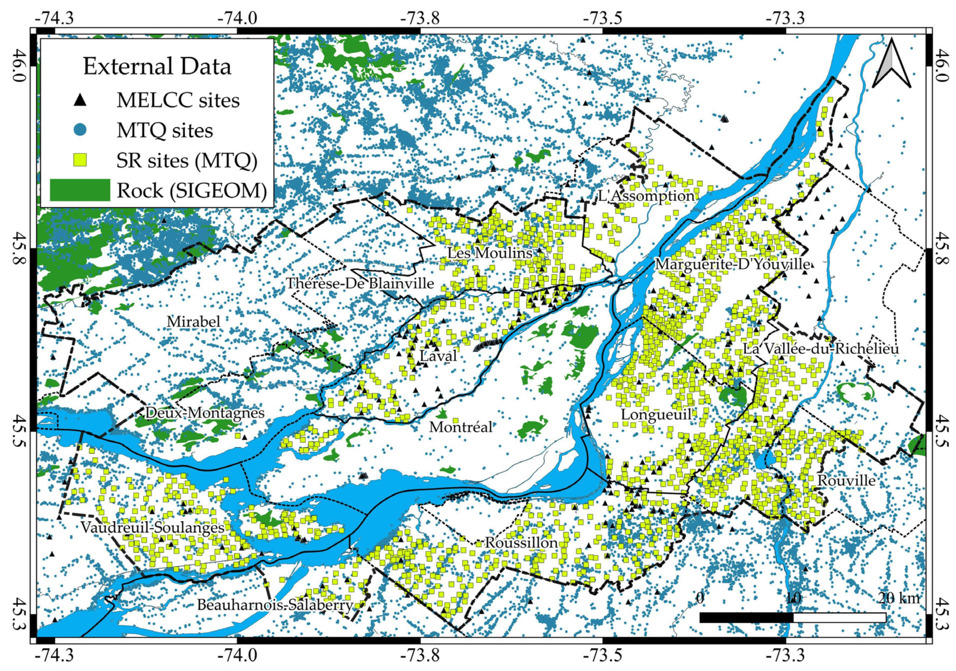
Figure 2. New borehole and geological data used in this study. Yellow squares locate seismic refraction data, and grey dots are boreholes from the Ministère des Transports Québec (MTQ). The black triangles are the wells data from Environnement Quebec (MELCC). Areas where bedrock outcrops are filled in green (from SIGEOM [24]). A dashed black line delimits the Montreal Metropolitan Community.
Geosciences 13 00256 g002

2.3. Vs Derived from the Seismic Refraction Data

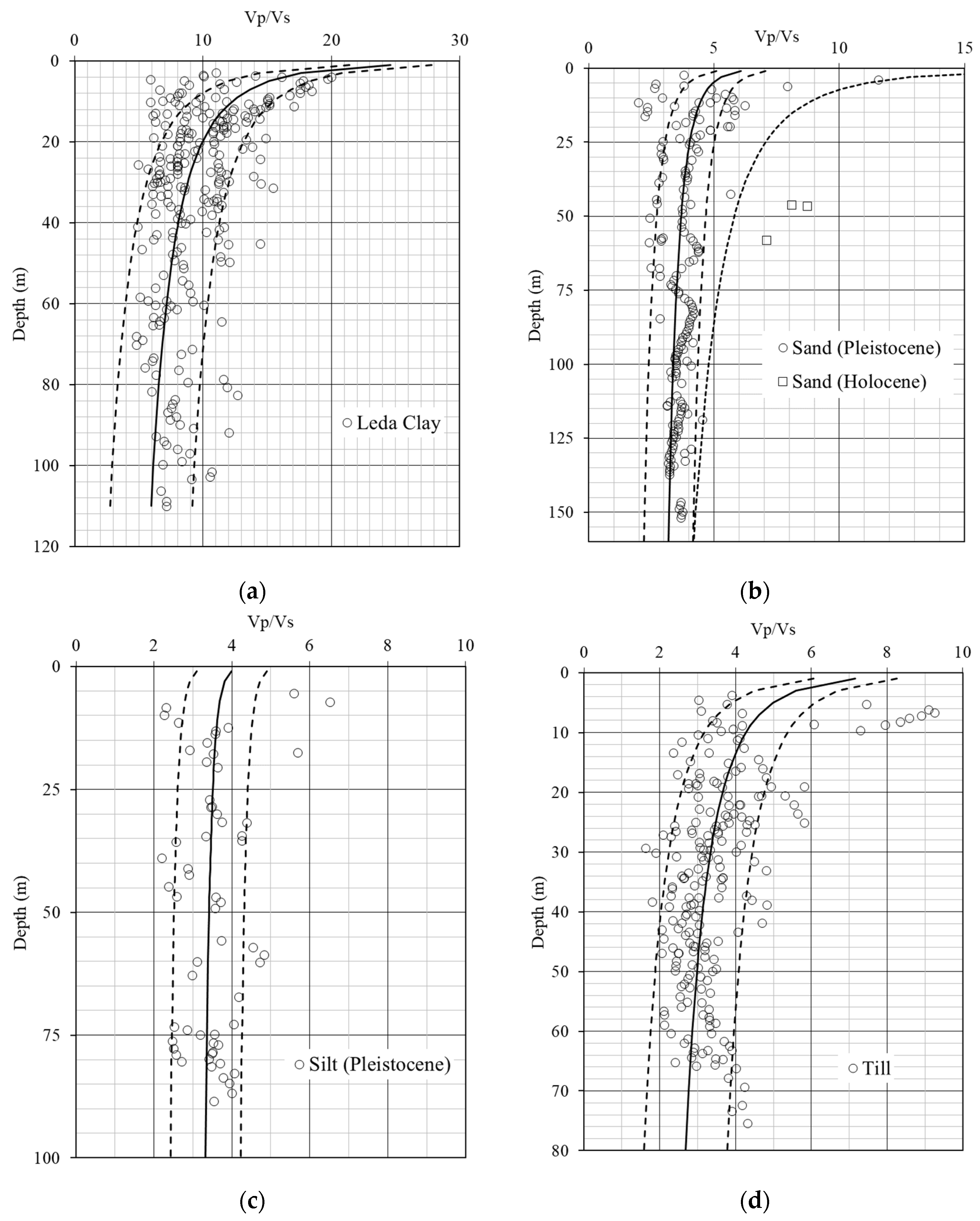
The SR data provide Vp profiles which need to be converted to Vs For that, the database from Hunter J. (unpublished, 2011), which compiles Vp and Vs velocities for different soil layers, is used. It includes data measured at different depths in several sites in Ontario for Leda clay, Pleistocene till (2.6 million to 11,700 years ago), as well as sand and silt of Pleistocene and Holocene (11,700 years to present) ages. These data are used to estimate a Vp/Vs relation with depth for each available soil type, as plotted in Figure 3.
The observations are fitted using a relation of the form:
V p V S = a ×   H b
where H is the depth in m. Table 2 lists the best-fitted parameters a and b, the standard deviation around the mean value, as well as the regression coefficient R2 for each soil type. The dataset for Holocene sand is not included in the table because it contains only four measurements, as shown in Figure 3.

2.4. Vs for Rock Using the Rock Quality Designation (RQD)

The Rock Quality Designation (RQD) is a parameter defining the degree of jointing in the rock and ranging from zero to 100%, the latter being the best quality rock. In order to consider this information when estimating Vs for rock, Talukder et al. [25] proposed a relationship as follows:
V Srock = 816.12 + 422 F
F is a value given for a range of RDQ percentage (1 for 0–20%, 2 for 20–40%, 3 for 40–60%, 4 for 60–80% and 5 for values higher than 80%). The average value of three is assumed when the RQD parameter is missing in borehole data (Vs30 = 2082 m/s).

3. Estimation of Vs30 from the Different Sources of Data

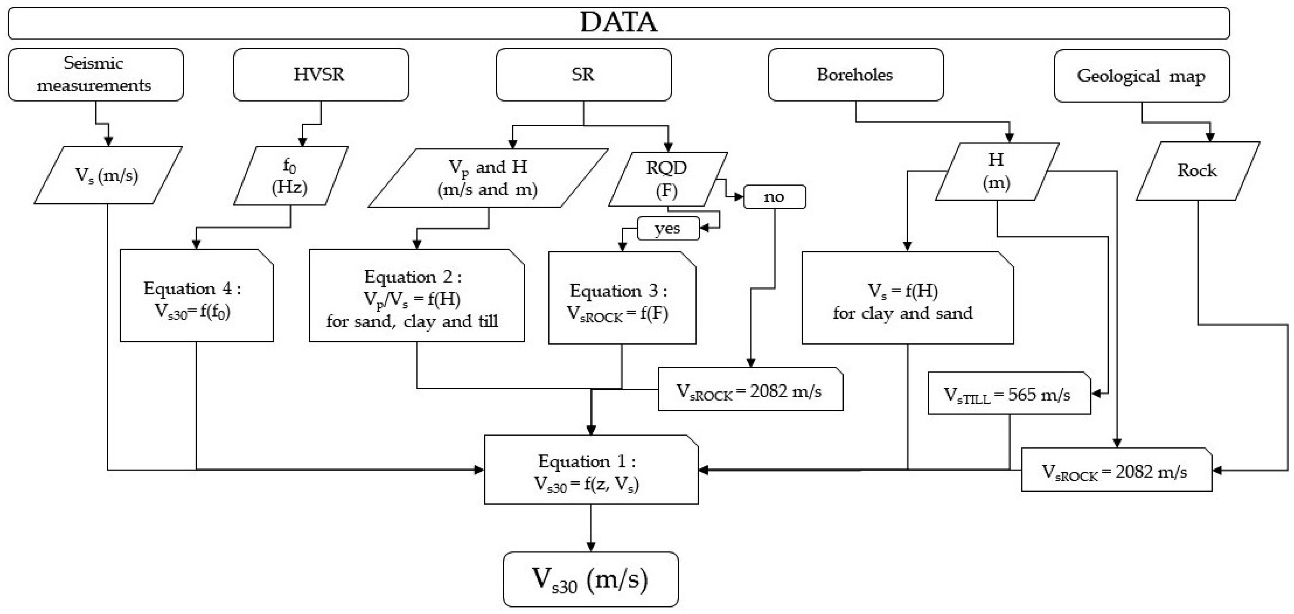
The proposed microzonation classifies local site response in site classes based on VS30, which is the averaged shear-wave velocity for the first 30 m of soil as calculated in Equation (1). It follows the classification used in the National Building Code of Canada (NBCC, [17]) and considers five classes from A to E defined by the Vs30 value (Table 1). Figure 4 is a flowchart describing the procedure used to calculate Vs30 for the different sources of data that are further detailed in this section.

3.1. Vs30 Estimates from Seismic Refraction Data

Vs30 is calculated using Equation (1) after converting Vp profiles to Vs using the relations Vp/Vs as described in Table 2 and Equation (2) for the rock. In several SR profiles, the soil type in one or two layers is undetermined (indicated as an unknown layer). Wherever possible, the unknown soil types were replaced with those identified in boreholes at similar depths and less than 250 m from the investigated site (a distance that corresponds to the maximum spatial correlation of Vs30). If no other sites are within 250 m, backfill material was assumed when Vp is lower than 750 m/s and sand when Vp is between 750 and 2000 m/s. The unknown layer with a Vp greater than 2000 m/s was assumed to be till, as this is the only type with high Vp values. A fixed Vs value of 155 m/s was assumed for backfill, as proposed by Rosset et al. [12].
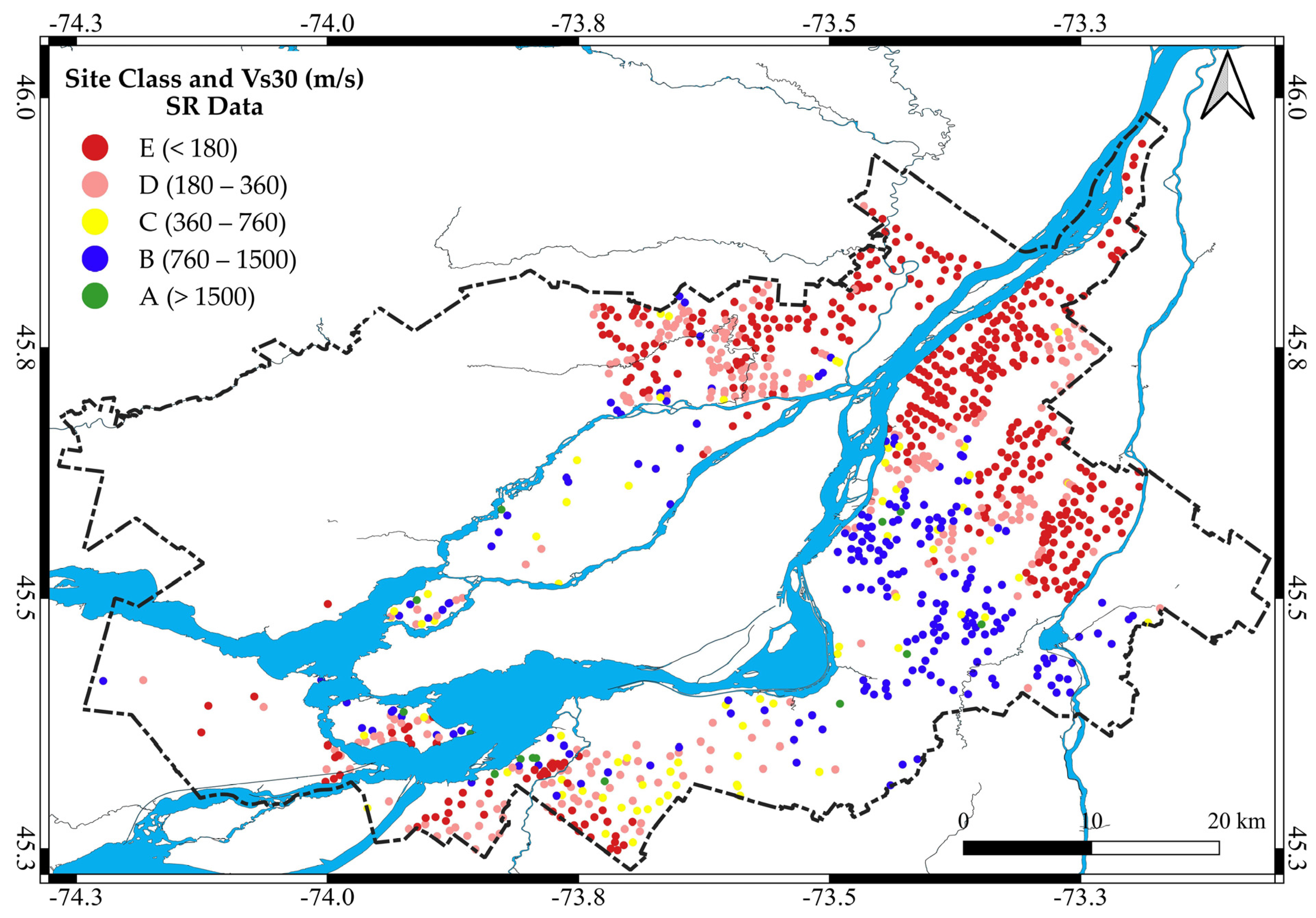
The large variability of Vp/Vs values for the Leda clay at shallow depths (5–10 m) in Figure 3a is largely influenced by the level of the groundwater table at the site. As this information is not available and is highly variable in time and space, the mean Vp/Vs value was chosen for all sites, as in Table 2. The sites with a clay layer in the upper 10 m represent 10% of the number of sites having a first layer as clay (which is less than 2% of the total number of SR sites). Vs varies between 60 and 100 m/s, values measured for clay at this depth by Mayne et al. [10] at the Canadian test site in Gloucester, Ontario. In total, VS30 is calculated for 1014 SR sites and classified into soil classes based on their values, as shown in the map of Figure 5.

3.2. Vs30 Estimates from Borehole Data

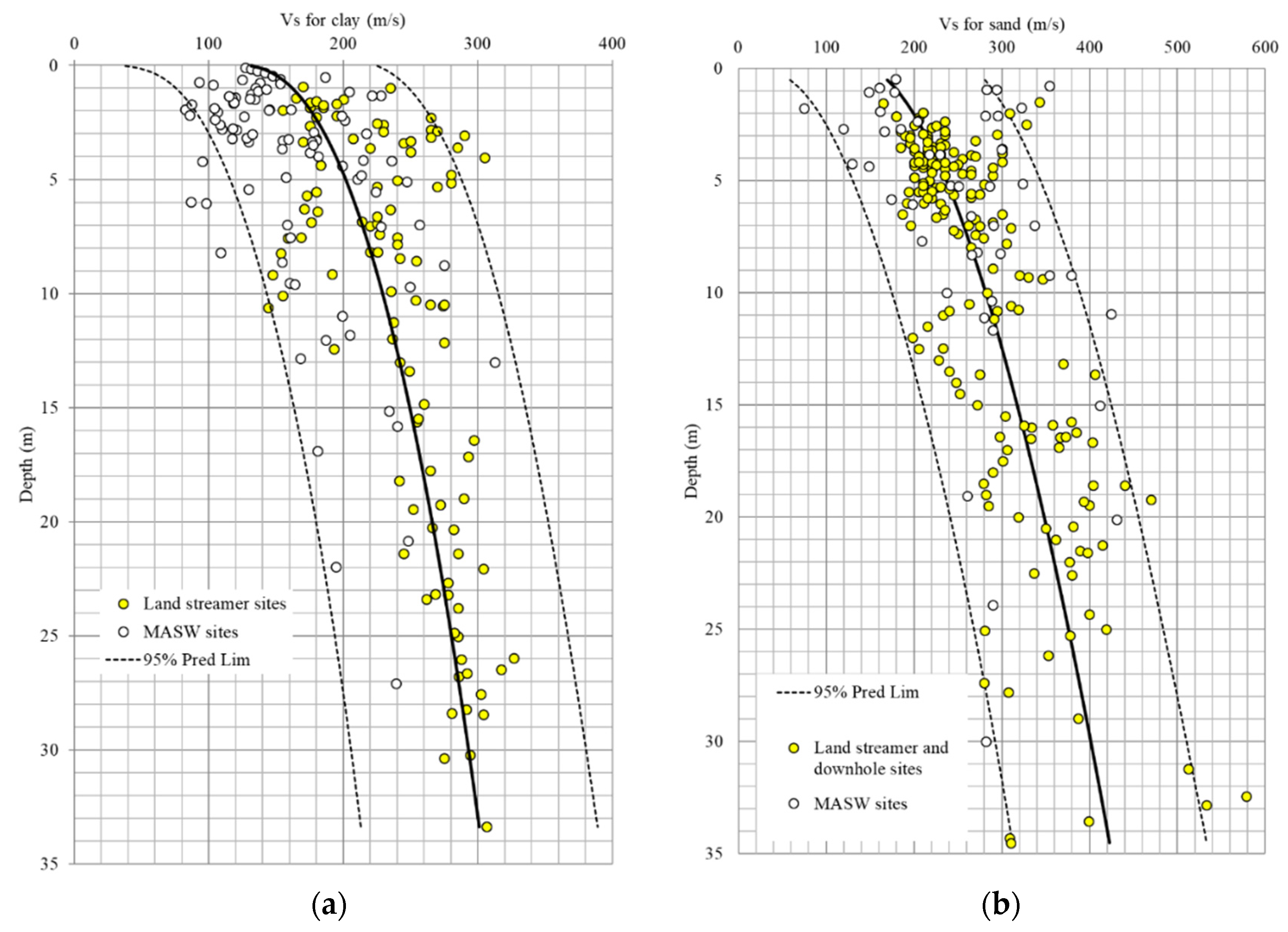
The two datasets of the MTQ and the MELCC are used to estimate VS30. Each selected borehole site includes information on the soil types, their relative thicknesses, as well as the RQD of bedrock. Vs values of the four main soil types (backfill, clay, sand and till) were estimated using the proposed Vs relation for the four prevalent soil layers in Montreal provided by Rosset et al. [12]. For clay and sand types, Vs profile with depth H is proposed combining various seismic measurements and borehole data. Table 3 lists the model coefficients, and Figure 6 show the data and model for sand and clay up to 35 m.
Vs values for tills range from 200 to 1300 m/s as given by MASW and downhole measurements. They are distributed in three groups of values that speculatively could be related to the differences in material composition correlated with the deposition history. However, due to the lack of till’s description in individual boreholes, the average value of 565 m/s with a standard deviation of 261 m/s is used. Bedrock in the MMC consists mainly of limestone and shale. Vs is calculated using Equation (2) when the RQD information is available or fixed at 2082 m/s corresponding to a median RQD of 40–60% for sites without RDQ values.
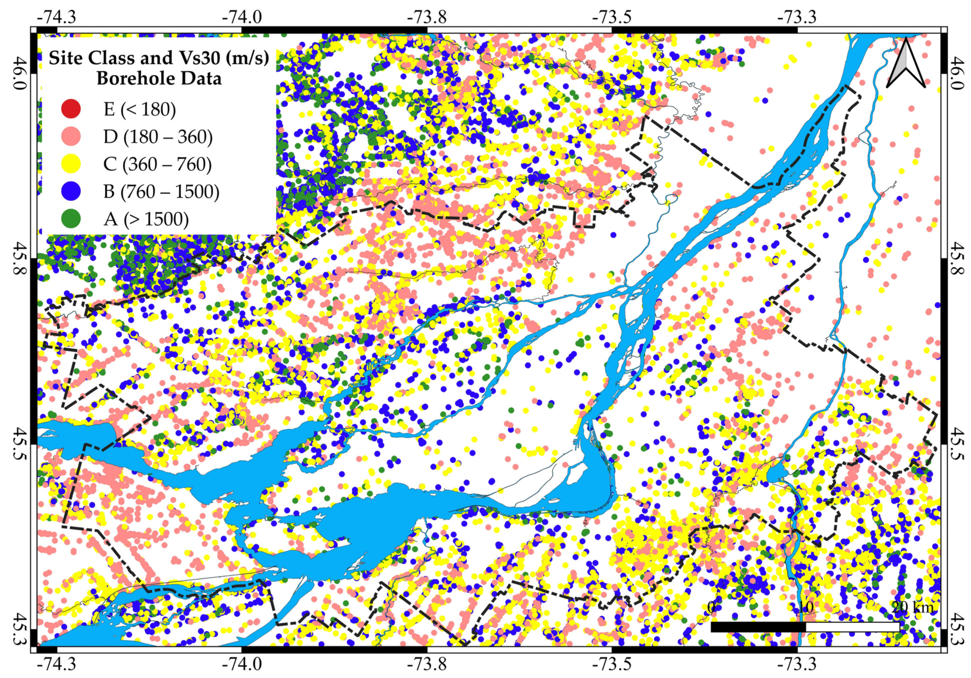
Within the MMC, Vs30 is calculated in 212,598 sites, as shown in the map of Figure 7 grouping sites in NBCC classes. In the Northwestern part of the MMC, the density of boreholes is high and clustered.

3.3. Vs30 Derived from HVSR Resonance Frequency

The HVSR method is a widely used analysis technique that estimates the fundamental frequency of a site through the calculation of the ratio of the Horizontal to Vertical Fourier (H/V) Spectra obtained from ambient noise or microtremor recordings. The influence of the soft soil thickness is correlated to the fundamental frequency (f0) by the general relationship f0 = Vs/4H where Vs and H are the shear-wave velocity and thickness of the soil layer. A three-component seismometer is used to record ambient noise for twenty-minute at a sampling rate of 128 Hz, which is sufficient to obtain stable, results [18]. Each ambient noise recording was analyzed with the Geopsy tool [26] in order to identify the frequency of the maximum amplitude peak of the HVSR.
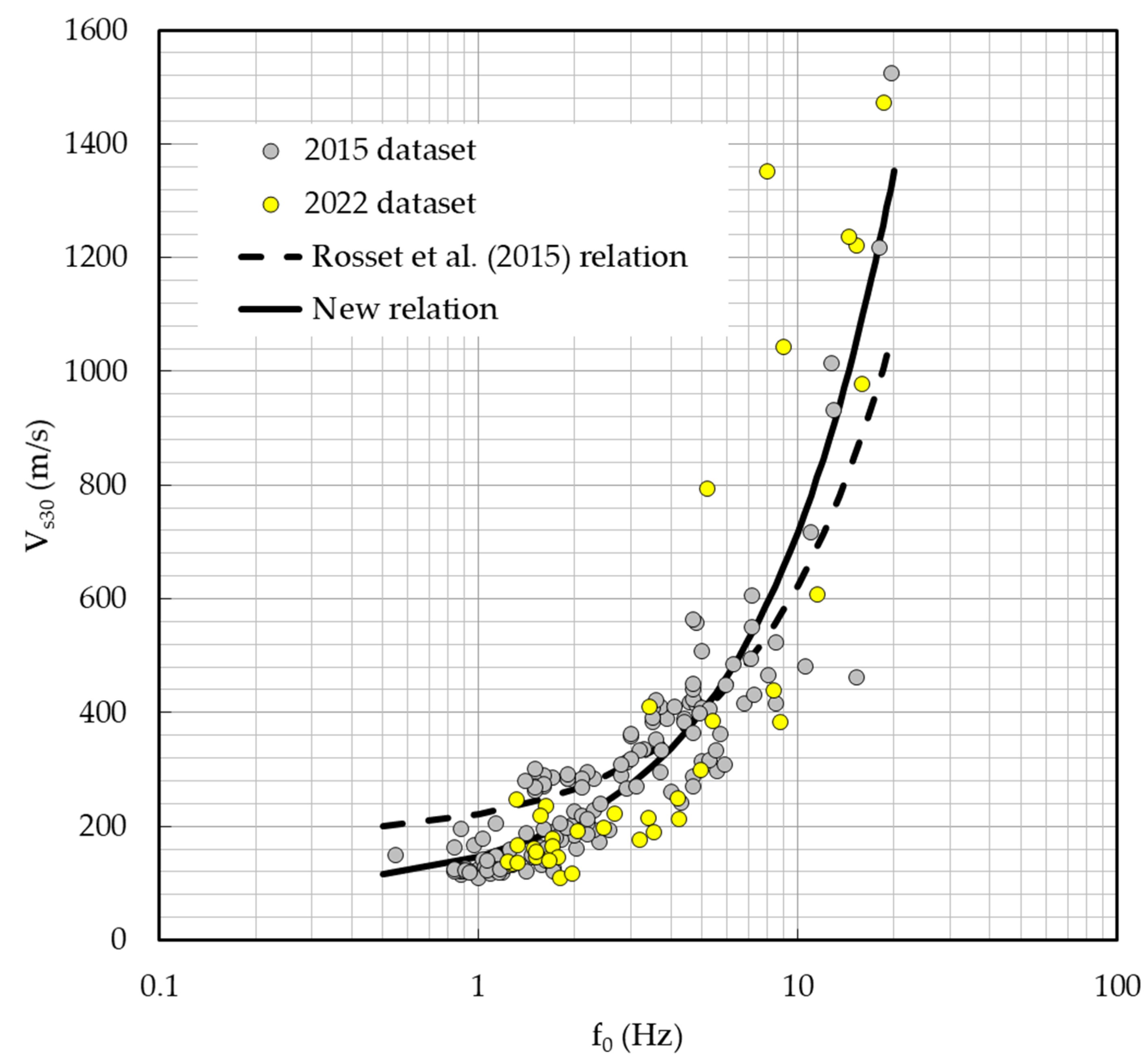
Most of the ambient noise recordings are from a 3-component sensor Tromino ®. The derived f0 is compared to the estimated Vs30 in sites at a distance less than 250 m of an HVSR site. Rosset et al. [12] developed a relation using 148 sites, mainly in Montreal, Laval and Longueuil, which is updated by 39 new sites acquired in 2022 in the neighborhood municipalities. The updated equation is of the form:
V S 30 = 63.454 f 0 + 83.479
The values of f0 and Vs30 at sites where both observations are available are plotted in Figure 8. The newly calculated regression equation (solid line) has a coefficient of determination R2 of 0.8 and a standard deviation of around 50 m/s. The dashed line shows the previous equation proposed by Rosset et al. [12].
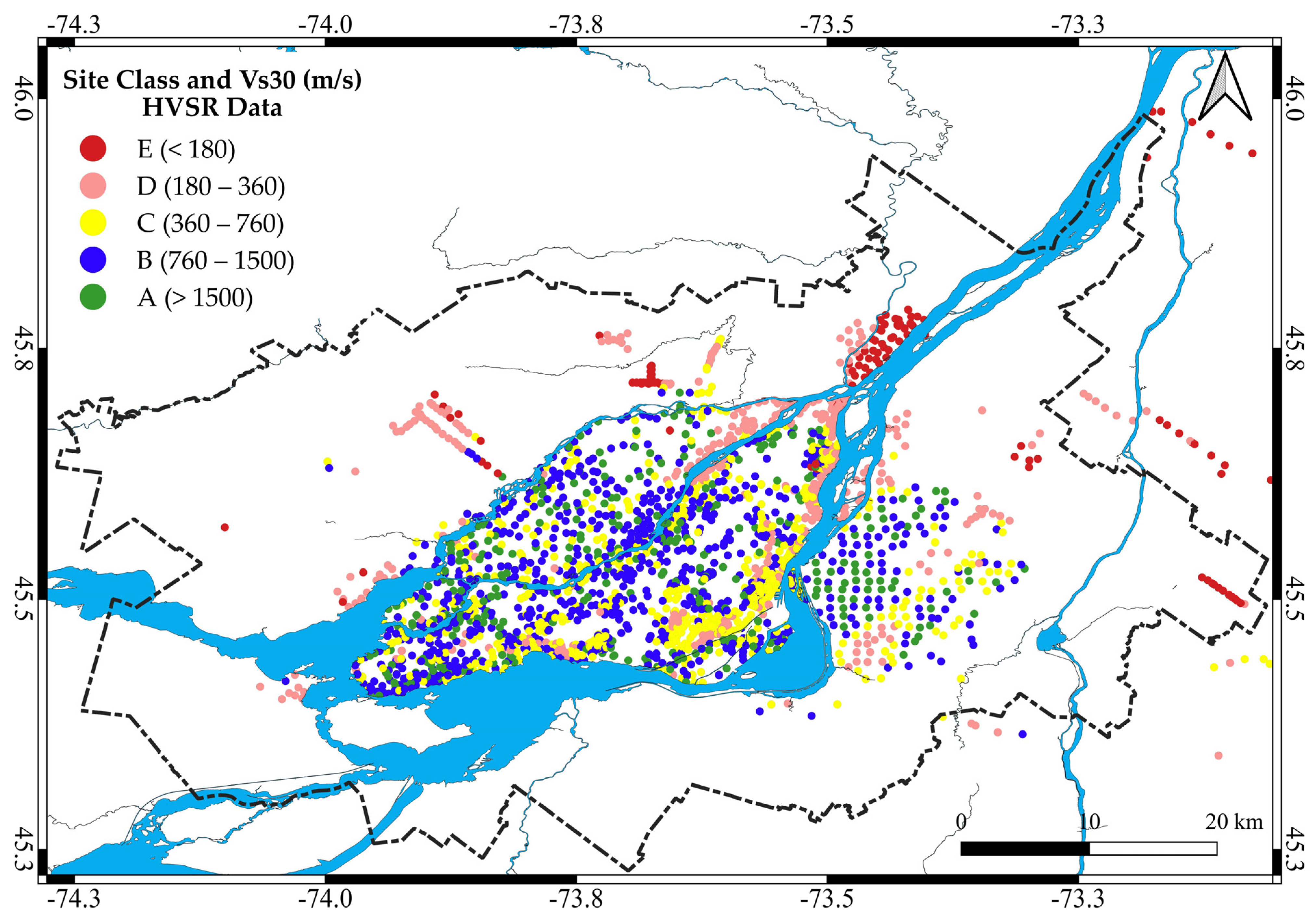
Vs30 value derived from f0 using Equation (3) is estimated for 2653 sites, as shown in the map in Figure 9. Among these sites, around 15% of them have a second frequency peak with lower H/V amplitude.

4. Microzonation in Terms of Vs30

A total of 229,387 sites where the Vs30 value is estimated from the different sources of data are used to produce a zonation map.
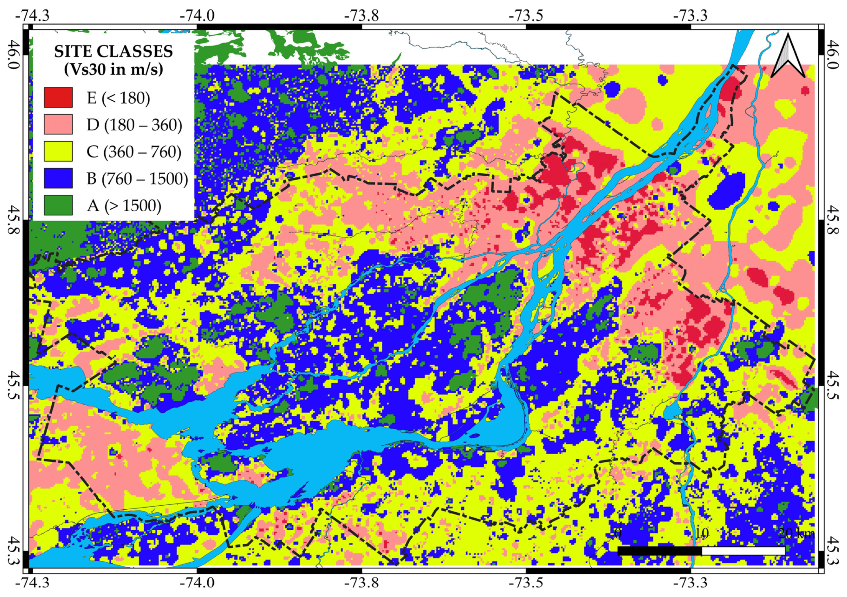
The values are interpolated in a grid of points equidistant of 0.01 degree in longitude and latitude (corresponding to a cell size of 300 m and 400 m, respectively) using the inverse distance weighted method [27] with the power parameter p fixed to 4. The selected region is a rectangle including the MMC with minimum and maximum coordinates (45.229° N, 74.268° W) and (45.984° N, 73.062° W). The interpolated Vs30 are grouped into ranges of values corresponding to the NBCC site classes shown in Table 1 (Figure 10). In addition, cells of the regular grid with outcropping bedrock are directly indicated as class A (Vs30 = 2082 m/s).
The results indicate that the Northeastern part of the MMC (Les Moulins, L’Assomption, Marguerite d’Youville and Vallée de Richelieu) is mainly in class D (Vs30 between 180 and 360 m/s) and E (<180 m/s) and are mainly derived from SR and HVSR data (Figure 5 and Figure 9, respectively). Vaudreuil-Soulanges, in the southwest part, is similar in class D from HVSR and borehole data (Figure 7). Thérèse de Blainville, in the north, is dominated by class D sites and derived mainly from borehole data (Figure 7).
Table 4 shows the distribution of site classes by data source. Site classes D and E predominate in the SR and field experiment data sets. For both of them, the selection of sites in zones where the thickest layer of soft soil was expected in Montreal Island is the first explanation for low Vs30 values. Borehole sites are mainly classified in classes B and C, with 21% of the sites in class A, while the HVSR data has 23% in class D and a relatively similar number in classes B and C. Again, the latter distribution is influenced by the selection of sites where soft soils were expected.

5. Discussion

In Figure 10, we propose the first Vs30 microzonation map for the region of Montreal using direct or indirect Vs profiles, borehole and geological data. It uses the approach developed earlier for the island of Montreal [12] by including a newly available online borehole dataset, unpublished seismic refraction data and additional sites investigated by the HVSR method. The latter is an effective non-invasive seismic survey method in terms of cost and time when sufficient data have been collected from MASW post-glacial sites to correlate the dominant frequency peak f0 with Vs30 (Equation (3)). Nevertheless, Motazedian et al. [14] indicate that in Ottawa, HVSR f0 underestimates the frequency based on the relation Vsav/4H, where Vsav is the average shear-wave velocity for postglacial sites with thicknesses greater than 50 m.
Seismic refraction profiles have three layers for which the soil type is not always specified. The data set of Vp/Vs values for similar soil types in Ontario helps us to convert the provided Vp values to Vs values for further calculation of Vs30. An improvement to refine the proposed regression equations in Table 2 could be to conduct seismic surveys at the location of multiple SR sites.
The borehole dataset is a useful complementary source of information when available but requires detailed information to correlate soil types and Vs estimates. In our case, the Vs30 uncertainty associated with this dataset is relatively high, and in several regions, the high density of sites could lead to a large discrepancy in the parameter, an indicator of the rapid spatial variability in the soil profiles. A preliminary analysis of the spatial correlation of Vs30 derived from borehole data indicates that only short correlation distances are significant. Future spatial interpolations should account for the spatial correlations and the uncertainties associated with Vs30 from each source and report best estimates, as well as their uncertainties as a function of location (Table 4).
The validation of the produced map is limited because the region of Montreal is rarely affected by earthquakes felt by many and by the lack of seismic instruments to record in several location weak motions. Nevertheless, Rosset et al. [11] have compared the distribution of site classes from three microzonation maps, including the one presented here, and the collected intensity data derived from the automatic Did You Feel It (DYFI) system operating since 2000 and from the reports collected on paper after the M5.8 1988 Saguenay earthquake. For the MMC, they used around 12,500 reports from 23 earthquake events (magnitude varying from 2.7 to 5.9) to estimate the mean felt intensity in a regular grid of cells considering the cells with more than four reports (400 cells over the 1865 cells with reports). They have shown that an increase in mean intensity of about 0.4 units with site class is observed in the MMC when moving from class A to E, suggesting that site conditions could influence the local perception of ground shaking [11]. The proposed site class’s distribution is superimposed on the calculated grid of felt intensity provided by Rosset et al. [11] in Figure 11.
In general, the cells with the highest values of intensity are located in site classes E (in red) and D (in purple) of the microzonation map (see [11] for further analysis). This is not true in some areas where site classes are B (in blue) or C (in yellow) and average intensity is higher than III. In other cases, low intensity is found in areas with site classes D to E, where we could expect site amplification. In both cases, these areas should be further investigated to confirm or infirm the citizen’s observations.

6. Conclusions

The next step, to account for the uncertainty associated with the different data sources, is to include a variable weight in the interpolation procedure and propose a second map showing the standard deviation. The high density of borehole data in certain regions will also be taken into account by averaging over a regular mesh the Vs30 values in order to consider the large spatial variability of the Vs30 value at short distances.
Table 5 gives an estimate of the standard deviation to be considered in the Vs30 calculation. For MASW, HRSR, and downhole sites, the estimate is fixed empirically at 30 m/s, as if the downhole method was expected to give more accurate results. For HVSR sites, the standard deviation calculated in Equation (4) is used. For SR and borehole data, the standard deviation is estimated by propagating the standard deviation given in the different equations in Section 2 and Section 3 in the calculation of Vs30. The standard deviation for the sites of the grid where the rock is identified from the digital geological map [24] is fixed at 100 m/s.
Information from Figure 11 will also be used to validate certain zones of the microzonation where reported intensities are not in line with expected trends, as has been done, for example, by Van Noten et al. [28] in the Anglo–Brabant Massif and the Lower Rhine Graben.
In addition, the deployment of NRCan strong motion instruments in the Montreal region as part of the National Earthquake Early Warning Network [29] will help to acquire new seismic records useful for comparing the distribution of site classes in Figure 10 and the spatial variability of their ground motion field.

Author Contributions

Conceptualization, P.R. and L.C.; methodology, P.R.; software, P.R. and A.T.; validation, P.R. and A.T.; formal analysis, P.R. and A.T.; investigation, P.R. and A.T.; writing—original draft preparation, P.R.; writing—review and editing, P.R.; project administration, L.C.; funding acquisition, L.C. All authors have read and agreed to the published version of the manuscript.

Funding

This research was funded by the NSERC, National Science and Engineering Research Council of Canada (grant ALLRP 567023-21), the Fonds de Recherche Nature et Technologie du Québec (Centre d’études interuniversitaire des structures sous charges extremes) and the Ministère de la Sécurité Publique du Québec (CPS 20-21-09). Participating students were supported by grants from the SURE program (Summer Undergraduate Research in Engineering) and from the Engineering Undergraduate Master Award of the University of McGill, Montreal.

Data Availability Statement

Data are available on demand.

Acknowledgments

The authors are grateful to all other contributors to field and laboratory data collection and interpretation since 2002, by alphabetic order; Adham Badran, Myriam Bour, Alejandro De La Puente, Jamil El Kazma, Majed Halawi, Brian Howard, Artur Kondrat’ev, Derek Kozak, Ricardo Mirando, Mona Qouqa, Salman Saeed, Graham Saunders, Christopher Schmelzle, Nuri Shrayer, Florence Sousha, Mohammad Talukder, Nicolas Truong, Keyan Yu and Alex Zahoruyko. We would like to thank the four reviewers and the editor for their constructive comments and suggestions. They have greatly improved the manuscript.

Conflicts of Interest

The authors declare no conflict of interest. The funders had no role in the design of the study; in the collection, analyses, or interpretation of data; in the writing of the manuscript; or in the decision to publish the results.

References

  1. Adams, J. A 65-year history of seismic hazard estimates in Canada. In Proceedings of the 12th Canadian Conference on Earthquake Engineering, Quebec City, QC, Canada, 17 June 2019; Available online: https://www.caee.ca/12CCEEpdf/192-cSSQ-149.pdf (accessed on 17 August 2023).
  2. Adams, J.; Allen, T.; Halchuk, S.; Kolaz, M. Canada’s 6th Generation Seismic Hazard Model, as Prepared for the 2020 National Building Code of Canada. In Proceedings of the 12th Canadian Conference on Earthquake Engineering, Quebec City, QC, Canada, 17 June 2019; Available online: https://www.caee.ca/12CCEEpdf/192-Mkvp-139.pdf (accessed on 17 August 2023).
  3. Leblanc, G. A closer look at the 16 September 1732, Montreal earthquake. Can. J. Earth Sci. 1981, 18, 539–550. [Google Scholar] [CrossRef]
  4. Rosset, P.; Chouinard, L.; Nollet, M.J. Consequences on Residential Buildings in Greater Montreal for a Repeat of the 1732 M5.8 Montreal Earthquake. In Proceedings of the Canadian Society of Civil Engineering Annual Conference 2021; CSCE 2021, Lecture Notes in Civil Engineering; Springer: Singapore, 2022; Volume 240, pp. 667–679. [Google Scholar] [CrossRef]
  5. Hobbs, T.E.; Journeay, J.M.; Rao, A.S.; Kolaj, M.; Martins, L.; LeSueur, P.; Simionato, M.; Silva, V.; Pagani, M.; Johnson, K.; et al. A National Seismic Risk Model for Canada: Methodology and Scientific Basis. Earthq. Spectra 2023, 39, 1410–1434. [Google Scholar] [CrossRef]
  6. Heath, D.C.; Wald, D.J.; Worden, C.B.; Thompson, E.M.; Smoczyk, G.M. A global hybrid VS30 map with a topographic slope–based default and regional map insets. Earthq. Spectra 2020, 36, 1570–1584. [Google Scholar] [CrossRef]
  7. Wu, W.; Liu, J.; Guo, L.; Deng, Z. Methodology and assessment of proxy based Vs30 estimation in Sichuan Province, China. Int. J. Disaster Risk Sci. 2020, 11, 133–144. [Google Scholar] [CrossRef]
  8. Rosset, P.; Zhu, H.; Chouinard, L. Influence of the Vs30 Mapping on the Residential Risk; Case Study of the Greater Montreal. In Proceedings of the Canadian Conference-Pacific Conference on Earthquake Engineering 2023, Vancouver, BC, Canada, 25–30 June 2023; Available online: https://az659834.vo.msecnd.net/eventsaircancprod/production-venuewest-public/6509145f89944833b174e9b568c5548b (accessed on 17 August 2023).
  9. Foti, S.; Hollender, F.; Garofalo, F.; Albarello, D.; Asten, M.; Bard, P.-Y.; Comina, C.; Cornou, C.; Cox, B.; Di Giulio, G.; et al. Guidelines for the good practice of surface wave analysis: A product of the InterPACIFIC project. Bull. Earthq. Eng. 2018, 16, 2367–2420. [Google Scholar] [CrossRef]
  10. Mayne, P.W.; Cargill, E.; Miller, B. Geotechnical characteristics of sensitive Leda clay at Canada test site in Gloucester, Ontario. AIMS Geosci. 2019, 5, 390–411. [Google Scholar] [CrossRef]
  11. Rosset, P.; Bent, A.; Halchuk, S.; Chouinard, L. Positive correlation of DYFI intensity data and microzonation in site classes for Ottawa, Quebec City and the metropolitan area of Montreal. Seismol. Res. Lett. 2022, 93, 3468–3480. [Google Scholar] [CrossRef]
  12. Rosset, P.; Bour-Belvaux, M.; Chouinard, L. Microzonation models for Montreal with respect to Vs30. Bull. Earthq. Eng. 2015, 13, 2225–2239. [Google Scholar] [CrossRef]
  13. Rosset, P.; Chouinard, L. Characterization of site effects in Montreal, Canada. Nat. Hazards 2009, 48, 295–308. [Google Scholar] [CrossRef]
  14. Motazedian, D.; Hunter, J.A.; Pugin, A.; Crow, H. Development of a Vs30 (NEHRP) map for the city of Ottawa, Ontario, Canada. Can. Geotech. J. 2011, 48, 458–472. [Google Scholar] [CrossRef]
  15. Molnar, S.; Assaf, J.H.; Sirohey, A.; Adhikari, S.R. Overview of local site effects and seismic microzonation mapping in Metropolitan Vancouver, British Columbia, Canada. Eng. Geol. 2020, 270, 105568. [Google Scholar] [CrossRef]
  16. Oliveira, L.; Teves-Costa, P.; Pinto, C.; Carrilho Gomes, R.; Almeida, I.M.; Ferreira, C.; Pereira, T.; Sotto-Mayor, M. Seismic microzonation based on large geotechnical database: Application to Lisbon. Eng. Geol. 2020, 265, 105417. [Google Scholar] [CrossRef]
  17. National Building Code of Canada; National Research Council of Canada. National Building Code of Canada; Canadian Commission on Building and Fire Codes: Ottawa, ON, Canada, 2015; Volume 1, 708p, Volume 2, 696p.
  18. Molnar, S.; Cassidy, J.F.; Castellaro, S.; Cornou, C.; Crow, H.; Hunter, J.A.; Matsushima, S.; Sánchez-Sesma, F.J.; Yong, A. Application of Microtremor Horizontal-to-Vertical Spectral Ratio (MHVSR) Analysis for Site Characterization: State of the Art. Surv. Geophys. 2018, 39, 613–631. [Google Scholar] [CrossRef]
  19. Bard, P.-Y.; Catello, A.; Aguacil, G.; Anastasiadis, A.; Atakan, K.; Azzara, R.M.; Basili, R.; Bertrand, E.; Bettig, B.; Blarel, F.; et al. Guidelines for the implementation of the H/V spectral ratio technique on ambient vibrations measurements, processing and interpretation. Bull. Earthq. Eng. 2008, 6, 1–2. [Google Scholar] [CrossRef]
  20. Pullan, S.E.; Pugin, A.J.; Hunter, J.A.; Cartwright, T.; Douma, M. Application of P-Wave Seismic Reflection Methods using the Landstreamer/Minivib system To Near-Surface Investigations. In Proceedings of the 21st EEGS Symposium on the Application of Geophysics to Engineering and Environmental Problems, Philadelphia, PA, USA, 6–8 April 2008. [Google Scholar]
  21. Park, C.B.; Miller, R.D.; Ryden, N.; Xia, J.; Ivanov, J. Combined use of active and passive surface waves. J. Environ. Eng. Geophys. 2005, 10, 323–334. [Google Scholar] [CrossRef]
  22. Hunter, J.A.; Crow, H.L. Shear Wave Velocity Measurement Guidelines for Canadian Seismic Site Characterization in Soil and Rock; Geological Survey of Canada, Open File; GEOSCAN: Ottawa, ON, Canada, 2012; pp. 1–227.
  23. Transport Quebec. Site D’Investigation Géotechnique. 2019. Available online: https://www.donneesquebec.ca/recherche/dataset/site-d-investigation-geotechnique/resource/7ba773b8-5b44-467e-ab39-5809f80d2c0a?inner_span=True (accessed on 17 August 2023).
  24. SIGEOM. SIGÉOM, Geomining Information System of Quebec, Gouvernment of Québec, Ministère de l’Énergie et des Ressources Naturelles. Available online: http://sigeom.mines.gouv.qc.ca (accessed on 17 August 2023).
  25. Talukder, M.K.; Rosset, P.; Chouinard, L. Reduction of Bias and Uncertainty in Regional Seismic Site Amplification Factors for Seismic Hazard and Risk Analysis. GeoHazards 2021, 2, 277–301. [Google Scholar] [CrossRef]
  26. Wathelet, M.; Chatelain, J.-L.; Cornou, C.; Di Giulio, G.; Guillier, B.; Ohrnberger, M.; Savvaidis, A. Geopsy: A User-Friendly Open-Source Tool Set for Ambient Vibration Processing. Seismol. Res. Lett. 2020, 91, 1878–1889. [Google Scholar] [CrossRef]
  27. Shepard, D. A two-dimensional interpolation function for irregularly-spaced data. In Proceedings of the 1968 ACM National Conference, New York, NY, USA, 27–29 January 1968; pp. 517–524. [Google Scholar] [CrossRef]
  28. Van Noten, K.; Lecocq, T.; Sira, C.; Hinzen, K.-G.; Camelbeeck, T. Path and site effects deduced from merged transfrontier internet macroseismic data of two recent M4 earthquakes in northwest Europe using a grid cell approach. Solid Earth 2017, 8, 453–477. [Google Scholar] [CrossRef]
  29. Cassidy, J.F.; Brillon, C.; Seywerd, H.; Kaya, Y.; Hassani, B. Updates on Canadian Strong Motion Monitoring and Data Access. In Proceedings of the Canadian Conference-Pacific Conference on Earthquake Engineering 2023, Vancouver, BC, Canada, 25–30 June 2023. [Google Scholar]
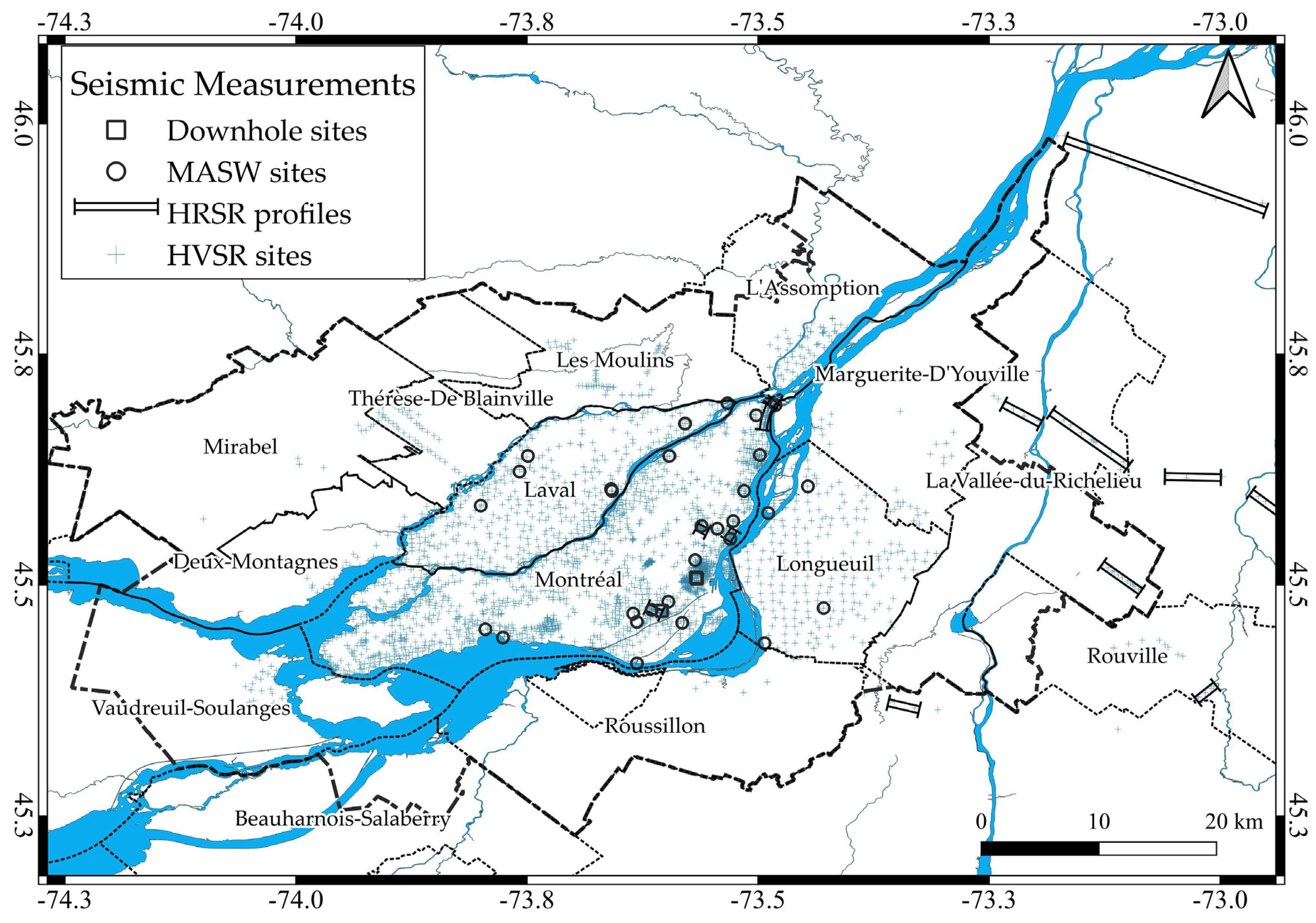
Figure 1. Sites with seismic measurements used in this study. Dashed black line delimits the Montreal Metropolitan Community and the municipalities are in thinner dashed lines with their name.
Geosciences 13 00256 g001
Figure 3. Vp/Vs relation with depth for the different soil deposits. (a) Clay, (b) Holocene sand with squares and Pleistocene with circles, (c) Pleistocene silt and (d) Till. Black lines are the fitted relation for each soil type, except for Holocene sand, which is a dashed line. Respective ± standard deviation curves are drawn with light dashed lines.
Geosciences 13 00256 g003
Figure 4. Flowchart of the proposed model to estimate Vs30 from the different sources of data. HVSR: Horizontal-to-Vertical Spectral Ratio; SR: Seismic Refraction. H is the depth, Vp and Vs are the seismic velocity for P and S-waves, respectively. Z is the thickness of the layer. RQD is the Rock Quality Designation. Table 2 gives the parameters of the Equation (2).
Geosciences 13 00256 g004
Figure 5. Vs30 value derived from seismic refraction (SR) sites grouped into site classes.
Geosciences 13 00256 g005
Figure 6. Shear-wave velocity relation with depth for (a) clay and (b) sand.
Geosciences 13 00256 g006
Figure 7. Vs30 values derived from new boreholes grouped into site classes.
Geosciences 13 00256 g007
Figure 8. Relation between f0 and VS30. The 2015 dataset is in grey dots, and the 2022 one is in yellow. A dashed line indicates the relation from Rosset et al. [12] and a solid line draws the new relation from Equation (4).
Geosciences 13 00256 g008
Figure 9. Vs30 estimate from Horizontal-to-Vertical Spectral Ratio (HVSR) sites grouped by site classes.
Geosciences 13 00256 g009
Figure 10. Vs30 map grouped in site classes (Table 1) using Inverse Distance Weighted interpolation procedure.
Geosciences 13 00256 g010
Figure 11. Comparison of average intensity from DYFI data and the site class’s microzonation using the uniform IDW procedure. The average MMI for cells with at least five reports is shown by circles with size proportional to the intensity. Values higher than III are written in the circle (from [11]).
Geosciences 13 00256 g011
Table 1. Seismic site categories based on VS30 as defined in [17].
Site ClassSoil TypeVs30 (m/s)
AHard rock>1500
BRock760–1500
CVery dense soil or soft rock360–760
DStiff soil180–360
ESoft soil<180
Table 2. Vp/Vs fitted parameters (Equation (2)) and regression coefficient for the different geological deposits.
Soil TypeGeological AgeabNumber of SitesStandard DeviationR2
ClayHolocene24.587−0.3022523.20.68
SandPleistocene6.0834−0.12821310.40
SiltPleistocene3.9935−0.04610.90.14
TillPleistocene7.1573−0.2243171.10.20
Table 3. Vs relation with depth H for clay and sand (from [12]).
Soil TypeRelationabcStandard DeviationR2
ClayVs = a + b H c121.240.80.43450.43
SandVs = a + b H c144.836.80.57540.49
a, b and c are the fitted parameters in the relation.
Table 4. Repartition of the sites by site classes and sources of data.
Site TypesABCDENumber of Sites
Boreholes21.1%31.1%33.6%14.1%-212,598
Geology100% 12,973
HVSR1.9%39.1%32.8%23.0%3.1%2653
SR1.2%20.4%6.4%27.0%45.0%1014
MASW, HRSR and downhole0.7%2.0%24.2%38.3%34.9%149
Table 5. The number of sites used in the Vs30 interpolation by sources of data and estimated associated standard deviation.
Sites TypeNumber of SitesSource of InformationEstimated Standard Deviation on Vs30 (in m/s)
MASW 29Field measurements30
HRSR 13Field measurements30
Downhole 3Field measurements30
HVSR 2653Field measurements50
SR 1014MTQ75
Boreholes212,598MTQ and MELCC100
Geology12,973SIGEOM100
Disclaimer/Publisher’s Note: The statements, opinions and data contained in all publications are solely those of the individual author(s) and contributor(s) and not of MDPI and/or the editor(s). MDPI and/or the editor(s) disclaim responsibility for any injury to people or property resulting from any ideas, methods, instructions or products referred to in the content.