Article

Updated Understanding of the Ripley Landslide Kinematics Using Satellite InSAR

Department of Civil and Environmental Engineering, University of Alberta, Edmonton, AB T6G 2R3, Canada
*
Author to whom correspondence should be addressed.
Geosciences 2022, 12(8), 298; https://doi.org/10.3390/geosciences12080298
Submission received: 22 June 2022 / Revised: 21 July 2022 / Accepted: 26 July 2022 / Published: 30 July 2022

Abstract

:
The Thompson River valley hosts 14 landslides along a 10 km section, which threaten the two major railroads connecting the Port of Vancouver and the interior provinces in Canada. The Ripley landslide is one of the active landslides in this section of the valley. Previous research at this site included an analysis of landslide deformations using satellite radar interferometry focusing on deformations measured in the line of sight between the satellite and the slopes, and average downslope displacement (deformations projected in the average downslope direction). Since then, further stratigraphic interpretation has provided an enhanced understanding of the Ripley landslide. In this update, the new stratigraphic interpretation is supplemented with satellite InSAR data from May 2015 to May 2017 to enhance the current understanding of the landslide kinematics. The results indicate that the Ripley landslide has been moving at a rate between 2 and 82 mm per year, corresponding to a very slow to slow landslide. It is also observed that the movements tend to be near-horizontal on areas closer to the toe of the landslide, while the vertical component of deformation increases near the scarp of the landslide. This, together with the interpreted stratigraphy, indicates the kinematics corresponds to a compound landslide. This is consistent with interpreted landslide kinematics of older, more mature landslides in the area that have shown episodes of retrogression and suggests the possibility of a similar future behaviour of the Ripley landslide.

1. Introduction

Geohazards threaten many infrastructures, as well as lives, all around the world. Historically, there are many reported cases of loss of life and damage to infrastructure in Canada as a consequence of landslides [1,2,3,4]. Since 1771 there have been hundreds of fatalities and damage to infrastructure caused by landslides in Canada, which have cost millions of dollars annually [5]. A recent reminder of the harmful potential of landslides in Canada was the four fatalities confirmed in a recent landslide on British Columbia’s Highway 99 in November 2021 (Simon Little, Global News, 20 November 2021). In addition, climate change and accelerated glacier melting and retreat can increase landslide activity in northern regions in Canada [3]; therefore, continued monitoring and understanding of landslide phenomena becomes important for resilience against climate change.
Identification of landslides and monitoring the terrain’s movement is one of the most effective risk management approaches for areas susceptible to landslides, particularly when stabilization or avoidance are technically or economically challenging. Monitoring can help to adapt to these landslide phenomena and inform adequate maintenance scheduling of infrastructures. Monitoring can also provide robust early warning systems [6,7]. Particularly, remote monitoring information can be used to increase our understanding of landslide kinematics and triggers, therefore enhancing landslide risk management strategies [8,9,10,11,12,13]. This paper presents an updated understanding of the landslide kinematics using satellite InSAR for the Ripley landslide in the province of British Columbia, Canada. The Ripley landslide has been studied by a number of researchers [14,15,16,17]. Previous research included an analysis of landslide deformations using satellite radar interferometry focusing on deformations measured in the line of sight between the satellite and the slopes and average downslope displacement (deformations projected in the average downslope direction) [16]. Since then, further stratigraphic interpretation has provided an enhanced understanding of the geometry of the shear surfaces in the Ripley [6,14,17,18,19]. In this update, the new stratigraphic interpretation is supplemented with satellite InSAR data from May 2015 to May 2017 (Sentinel 1) to enhance the current understanding of the landslide kinematics.

1.1. Landslide Remote Sensing and Satellite InSAR

New technologies facilitate geotechnical engineers’ real-time observation of a terrain’s movement. Remote sensing, GPS monitoring, geophysical imaging and geotechnical investigation are commonly applied for landslides characterization [20]. Remote sensing methods such as interferometric synthetic aperture radar (InSAR), light detection and ranging (LiDAR), and unmanned aerial vehicle (UAV) photogrammetry are applied to monitor cut slopes and natural slopes in current routine geohazard monitoring programs. These technologies help engineers to acquire data over large areas with high spatial resolution in comparison to in-place instruments such as slope inclinometers or survey monuments [7].
Interferometric synthetic aperture radar (InSAR) has been used in many worldwide applications to detect surface displacements of crustal deformation, glacier motion, infrastructure displacement and landslides in recent decades [21,22,23,24,25,26,27,28,29,30,31,32].
In this method, radar satellites carry SAR sensors that utilize wavelength information to calculate distance to the surface and that can be used for calculating relative change [24].
InSAR has become a reliable, accurate and near-real-time method to monitor potential landslide events and is particularly useful in remote areas where in-place ground monitoring instruments are technically or economically challenging. Although InSAR has been extensively used for monitoring landslides in the last three decades, particularly slow moving landslides, it is still challenging to find adequate data to generate InSAR calculations for rapid landslide acceleration. Other challenges include atmospheric noise, vegetation cover and seasonal effects, such as rainfall and snow cover [5]. Notwithstanding these limitations, the ability of InSAR to provide ground deformation measurements with high accuracy makes this method an effective technique in many applications focused on deformation phenomena that occur on the Earth’s surface [33]. Satellite InSAR has been proven to be an effective method for identifying and monitoring ground displacement of slow to extremely slow moving slopes. InSAR information can be used for enhanced understanding of landslide mechanisms when complemented with other monitoring information such as precipitation and ground water fluctuation. The resolution of InSAR monitoring (sub cm/year) and its significant ability to capture massive areas make it very useful for widespread surface monitoring of landslides. It is important to note that satellite revisiting times (now between 1 day and 1 week) limit the temporal resolution of InSAR monitoring. Ground-based InSAR can provide adequate high-frequency data for forecasting the rapid acceleration that develops in a window of hours. No sites will have more frequent access than a one-day revisiting time. In this regard, the information is valuable for identifying the initiation of ground displacements, changes in displacement trends and seasonal displacements; however, it would not provide adequate warning for failure modes that lead to rapid acceleration followed by collapse that develop in just a few days as the variability of monitoring points could mask reliable identification of acceleration [34].

1.2. The Thompson River Valley Landslides South of Ashcroft and the Ripley Landslide

The Thompson River valley south of Ashcroft hosts one of the most important transportation corridors in Canada. Both the Canadian Pacific Railway (CP) and Canadian National Railway (CN) use this corridor to transport goods between the Port of Vancouver and the rest of Canada (Clague and Evans, n.d.). The Thompson River valley became a monitoring priority for Natural Resources Canada (NRCAN), the Geological Survey of Canada (GSC) and Transport Canada (TC) because of its economic importance and effects on transportation services in Canada and it is considered essential to understand and manage the risks associated with the landslides that threaten the corridor [34].
The Thompson River valley was formed by a series of glaciations and later exposed to river erosion and incision. The valley is infilled with a complex sequence of a wide range of deposits, from poorly sorted sand and gravel to rhythmically interbedded silt and clay. This corresponds to multiple glacial advance and retreat intervals in the Pleistocene [16,35,36]. The extensive terrace that hosts several landslides was formed during postglacial times when the southward-flowing Thompson River down-cut 150 m of deposited sediments gradually along the valley [16,37]. In these landslides, the existence of steep internal shears and basal through-going shear surfaces, as well as the presence of multiple graben and horst features, confirms the presence of a weak silt and clay layer that is considered responsible for the instability of many of these landslides [16,35,38]. This weak layer contains pre-sheared surfaces with residual shear strengths characterized by no cohesion and friction angles between 9 and 16 degrees, according to landslide back-analyses [14].
Fourteen landslides have been identified in the Thompson River valley, 12 of them traversed by one or both railway companies. The first reported landslide dates to the 1860s and periodic reactivation and slope movements have occurred since then. The location and extents of the landslides are shown in Figure 1 [14].
Landslides in this valley have volumes between 0.75 million cubic meters (Ripley landslide—Figure 1) and 15 million cubic meters (north slide—Figure 1), and their movement velocity range between 10 mm/year (extremely slow) and reported accelerated episodes of up to 50 mm/s historically (very rapid) [16].
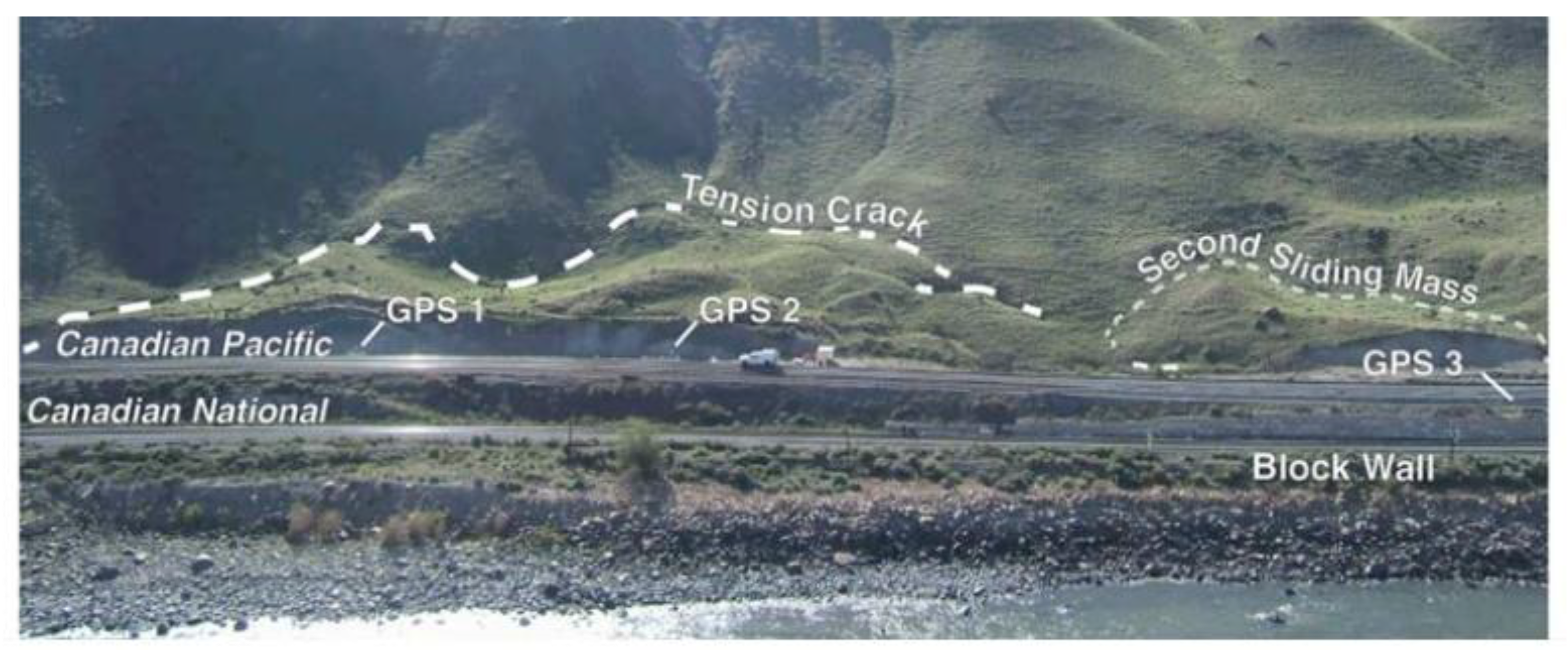
The Ripley landslide is approximately 200 m long, 40 m high and 300 m wide. A front view of the landslide is shown in Figure 2 [39]. The Ripley landslide was recognized by Charles Ripley in the 19th century by observation of an offset in a fence on the uphill side of CP railway tracks. Since then, the landslide has been inactive or moved slow enough that regular maintenance of track allows for continued operations of the CN and CP railways, which traverse this landslide. Shortly after construction of a section of track in 2005, the landslide showed some deformation and this movement was followed by the development of cracks and a scarp in 2007 [14]. Since then, the railway track and ballast has required adjustments at higher frequencies than for other sections of track [17]. The Ripley landslide is the only landslide currently being monitored at almost real-time, as it has become a field laboratory for novel investigation technology [6,14,15,16,17,18,40]. The other landslides in this area are being monitored with periodic slope inclinometer readings.
The Ripley landslide’s estimated volume of 750,000 m3 is relatively small in comparison to the other landslides in the Thompson River valley; however, it is one of the most active landslides with velocities between 25 and 180 mm/year (very slow, according to the classification by Cruden and Varnes [41].

2. Materials and Methods

2.1. Published Displacement Monitoring Data at the Ripley Landslide

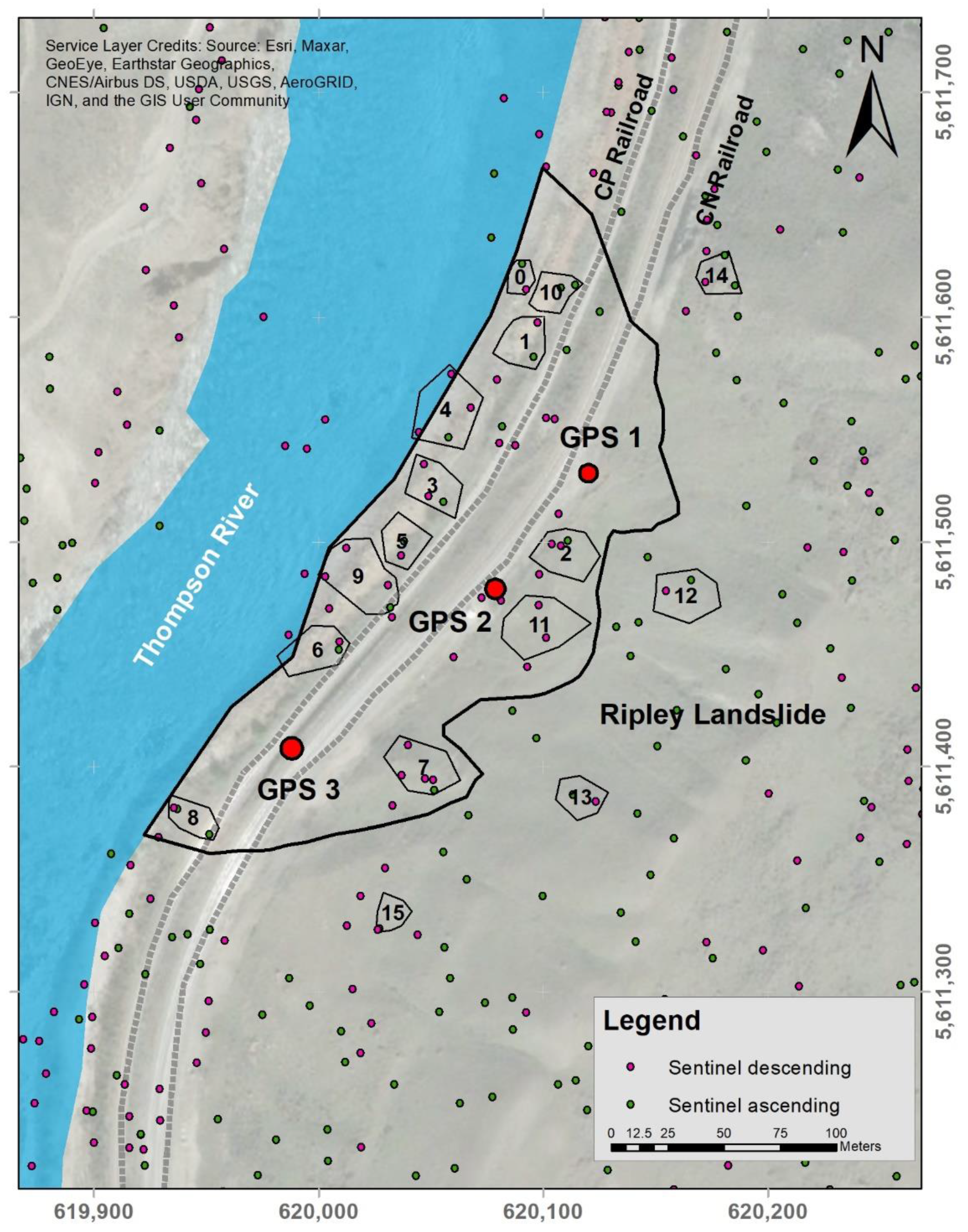
The GPS system monitoring data used in this paper was acquired through an installation by CP and analyzed by the University of Alberta under the Canadian Railway Hazard Research Program. The system consists of three GPS monitoring stations on the Ripley landslide, near the railway tracks and one reference station located on stable bedrock outside the unstable area. GPS stations are Leica single-phase receivers in a differential GPS mode, able to detect 12.5 mm of cumulative ground movement with a variability of ± 1 mm [15]. Lateral and vertical displacements are processed by the Leica GeoMOS software and information on the system’s latitude, longitude and vertical coordinates is provided at an hourly frequency. Hourly readings are used to calculate daily positioning of the GPS stations. The GPS displacement data in this paper corresponds to that published by Macciotta et al. [15] for the period between April 2008 and October 2014. (All three GPS started recording data in April 2008. GPS-1 and GPS-3 recorded data until 21 October 2014, while GPS-2 recorded data only until 29 April 2014. All three systems showed some data gaps associated with repairs and maintenance of the system.) These data are used to validate the landslide deformation trends (directionality) obtained by InSAR, assuming the landslide has not suffered changes in the direction of movement. Unfortunately, no displacement vector datasets coincide with the InSAR processing period in this paper. Positive values for horizontal movement show displacements in the downslope direction and negative vertical values show downward movement [15]. Figure 3 shows the proximate locations of each installed GPS system.

2.2. Satellite InSAR Displacement Data

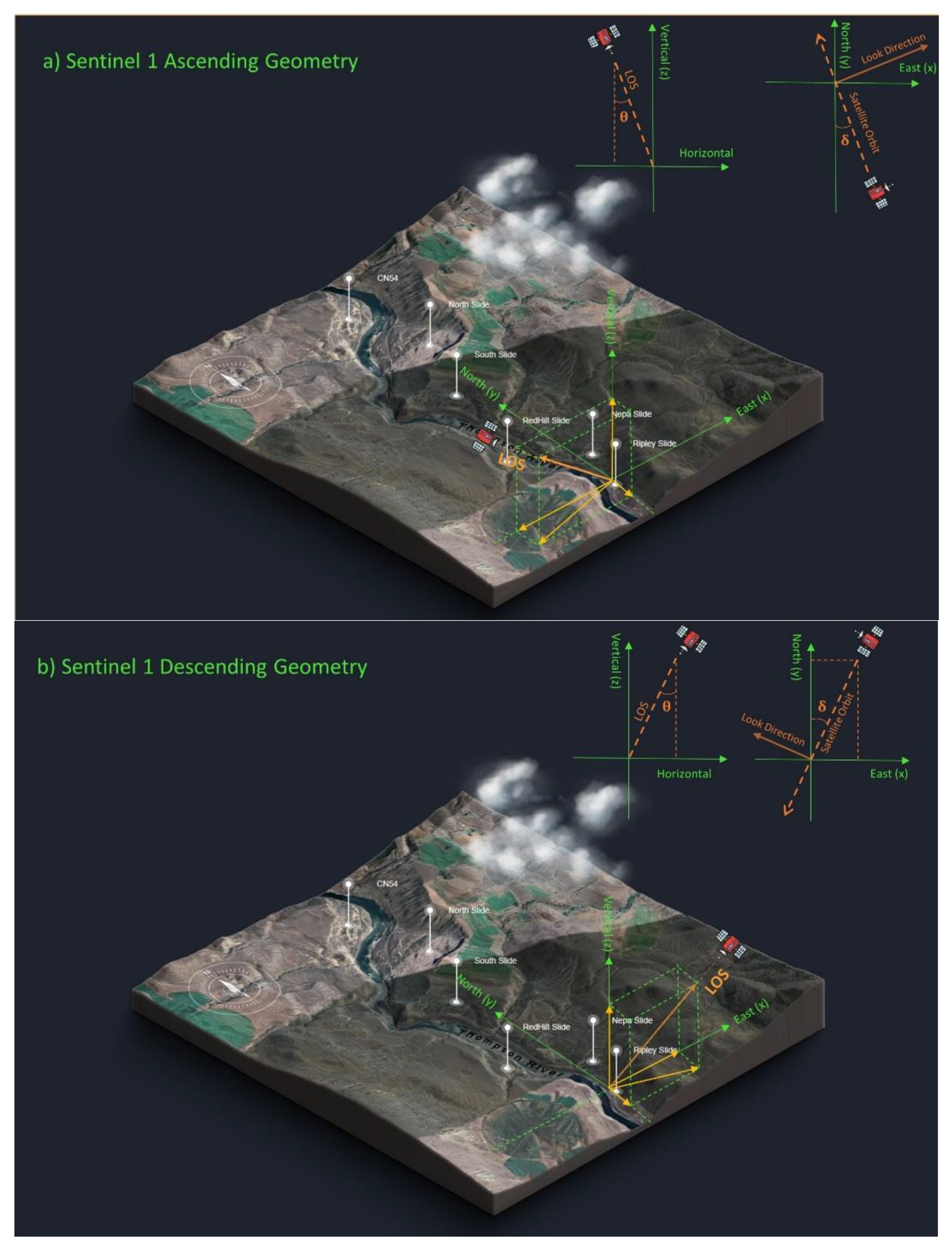
Satellite InSAR displacement data used in this paper were collected from Sentinel 1 and processed by TRE ALTAMIRA CLS Group Company. Processed information included displacements in the line-of-sight (LOS), which is the visual line between the satellite sensor and the points on the land being monitored between the end of 2014 to the Spring of 2018. The data with minimum gaps between May 2015 to May 2017 were selected to investigate the ground displacement of the Ripley landslide. The radar orbit is called ascending when a satellite moves from south to north and captures images, in our case, towards the east. The orbit is called descending when the satellite travels from north to south and captures images, in our case, to the west. There are two important angles for each satellite LOS to interpret the calculated displacements. These are the angle between the LOS and the vertical plane, or theta (θ), and the angle between each satellite’s orbit and the geographic north, or delta (δ). Figure 4 shows the typical angle layout for both ascending and descending satellite orbits.
Scatterers refer to data points that provide information for measuring the ground movement by LOS displacements. Permanent scatterers (PS) consist of some buildings, fences and other man-made structures and also some natural features such as rocks or exposed ground that are likely stable. Distributed scatterers (DS) correspond to large areas (up to hundreds of square meters) and were identified from exposed ground or fields. Although each DS presents an exact point for clarity of presentation, these points actually correspond to non-point features that are multiple pixels in size.
Table 1 illustrates a summary of properties of the data that were collected from each Sentinel orbit.
Both PS and DS data were provided by TRE using their SqueeSAR method, which incorporates PSInSAR processing methods.

Sentinel 1

Sentinel 1 was launched by the European Space Agency (ESA). Satellite images used in this study that cover the Ripley landslide were collected between 3 November 2014 and 17 March 2018 for the ascending orbit, and between 6 November 2014 and 1 April 2018 for the descending orbit. LOS angles are shown in Table 2.

2.3. Displacement Calculation at the Surface of the Ripley Landslide Based on InSAR LOS Displacements

In this paper, we propose a method for interpreting the geometry of the deformation based on the satellite InSAR, noting this should be complemented with a classical evaluation of the line-of-sight (LOS) deformations and velocities.
The LOS InSAR displacement is a projection of the true landslide surface displacement on its axis. The procedure followed in the paper aims at calculating a close approximation to these real displacements, although a few assumptions are required. For simplification, the calculated displacements are referred to as the “Real” displacement vectors (R), where “bold” represents a vector. Given the orbits of the satellites are sub-parallel to the north–south direction, resolving the north–south displacement component is not reliable. Therefore, a common assumption for landslide InSAR interpretation is to consider landslide motion in the downslope direction (azimuth and inclination) [16]. The work presented in this paper does not assume the directionality of movement in the vertical plane; however, it assumes movement in the horizontal plane with an azimuth parallel to the slope azimuth in the area of measurement. Therefore, knowing the topography of the landslide provides the assumed unit vector of the horizontal component of R. This can be accomplished by calculating the unit vector of R in the horizontal plane, considering the vertical component as an unknown, and projecting R to the LOS unit vectors (based on the satellite geometry). Knowing the LOS displacement magnitude, the vertical component of R and its magnitude can be solved.
The unit vectors of LOS are denoted by S a for Sentinel ascending and S d for Sentinel descending. The projections of R on these directions would be the measured LOS displacements and are denoted by vectors P a   and   P d , respectively, each with scalar magnitudes M a   and   M d . Therefore, Equation (1) presents the expression for P i , where i represents the ascending or descending orbits.
P i = ( R · S i )   S i = M i   S i
The components of R can be denoted as (x,y,z), and the components of the unit vectors of the LOS as S i = ( e , n , u ) . To find the LOS unit vectors, it is essential to use the angles between the LOS, the vertical plane and azimuth from Table 2 (Equations (2)–(4)).
u = cos θ
e = sin θ . sin δ
n = sin θ . cos δ
The coordinate system used in this paper corresponds to (east, north, up). The sign of u is positive and sign of n is negative for both orbits’ LOS, while the e sign is negative for the ascending orbit and it is positive for the descending orbit. The unit vectors are then calculated as:
S a = ( 0.613 , 0.123 , 0.781 )
S d = ( 0.692 , 0.095 , 0.716 )
Replacing Equations (5) and (6) into Equation (1) and solving for M a   and   M d provides the measured movements in the LOS in terms of the components of R (Equations (7) and (8)).
0.613 x 0.123 y + 0.781 z = M a
0.692 x 0.095 y + 0.716 z = M d
The third equation to resolve the components of R follows the assumption that the total horizontal vector component of R is parallel to the slope’s azimuth in the area of measurement (α) as follows:
x y = tan α
Equations (7)–(9) provide a system of three equations, three unknowns for estimating R. Scatterer locations for the different satellites and for different orbits are not the same. Therefore, this required selecting areas of the landslide where information from two orbits is available, and averaging all scatterers for each orbit within that area to calculate representative LOS displacements (Figure 5). The measurements are also not synchronous between orientations. Data from Sentinel ascending are gathered from November 2014 to March 2018 every 25 days while reported data is from November 2014 to April 2018 in 25-day intervals for Sentinel descending. This required the selection of relatively long periods of time for calculating average R (annual basis), such that differences of a few days would not have a meaningful impact on the results. The slope displacement rate of the Ripley landslide had been reported to be up to 150 mm/year (or 0.4 mm/day), suggesting that asynchronous measurements by less than two weeks for a total period of analysis of two years could represent approximately a 2% error.

3. Results

3.1. Satellite InSAR Results at the Ripley Landslide

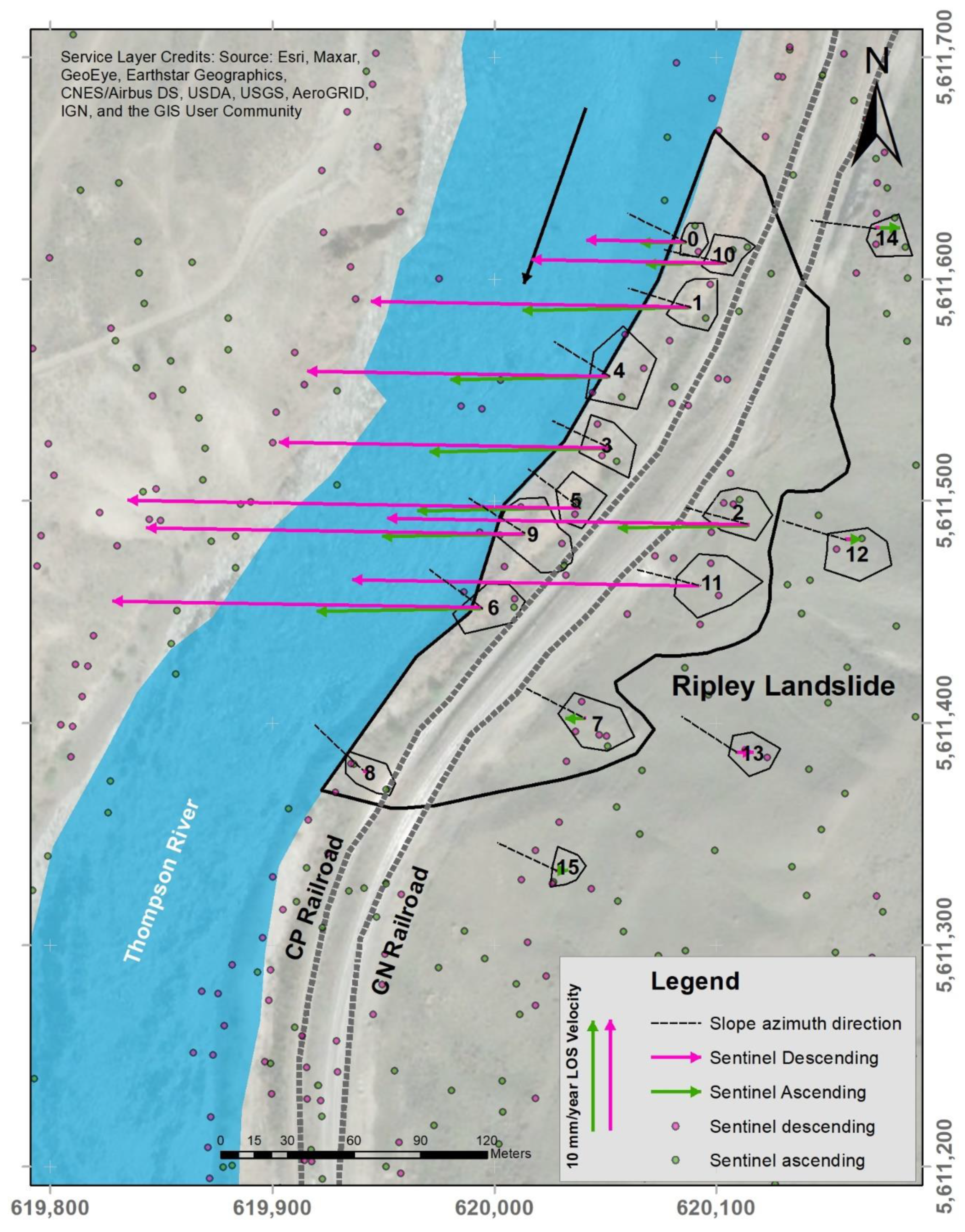
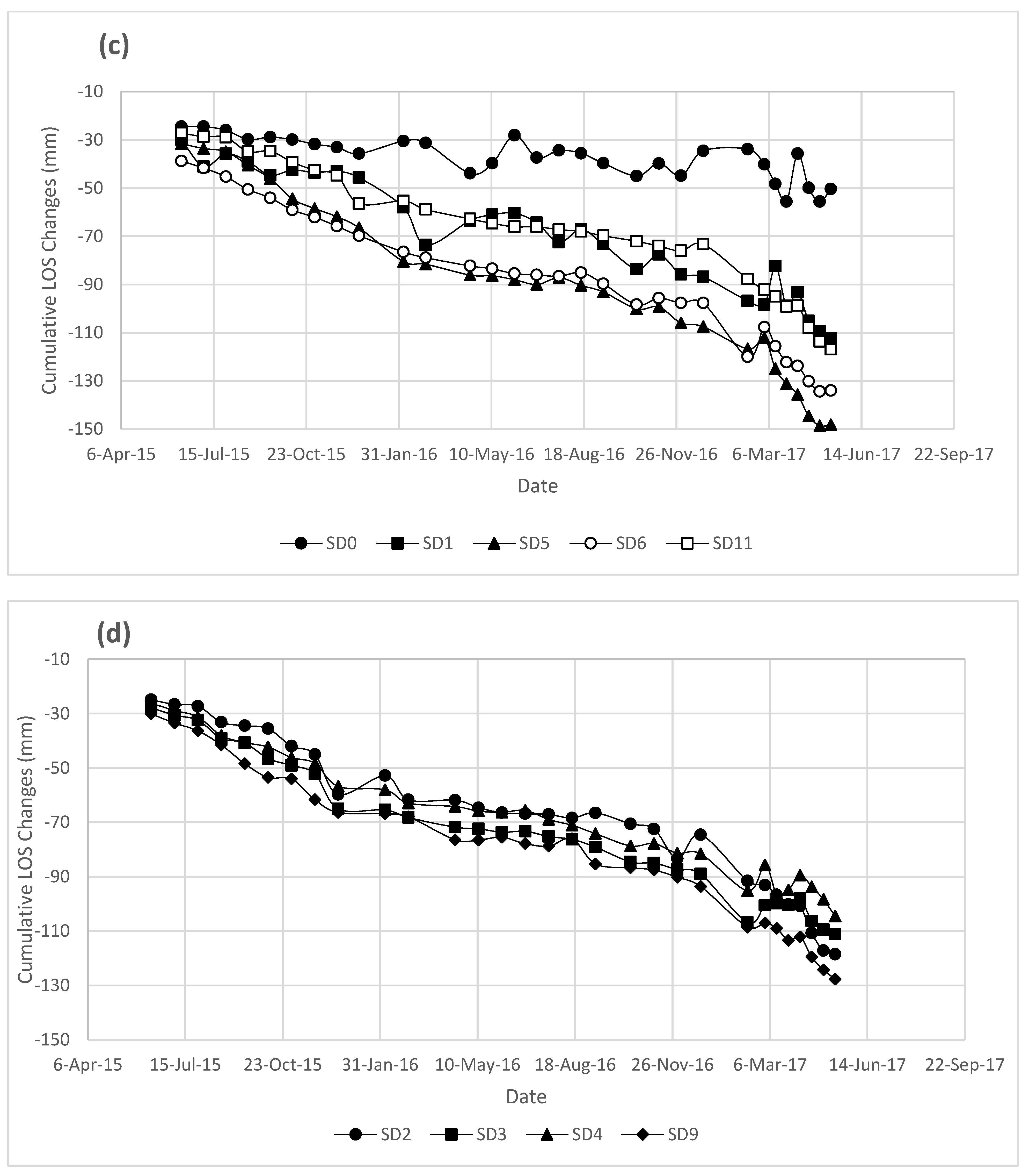
The LOS vectors in the horizontal plane for each area of analysis are shown in Figure 6. The magnitude and direction of LOS vectors for each area are located on the center of the area while it is representative of the average values for all captured points within the area. LOS directions for the same orbit are all parallel, given that LOS direction is defined by the orbit geometry. This figure also shows the direction of the average slope azimuth. It is observed that LOS magnitudes are large and of similar magnitude near the river, and significantly decrease near the back scarp of the landslide. Figure 7 shows the cumulative LOS deformations for each area for both Sentinel ascending and Sentinel descending orbits. Acceleration periods tend to start in the fall and deacceleration tends to start in the spring. These show clear episodes of acceleration and deceleration, consistent with previous observations [14,15,16]. In this published study the acceleration corresponds to the drawdown effect of the Thompson River on the Ripley landslide.
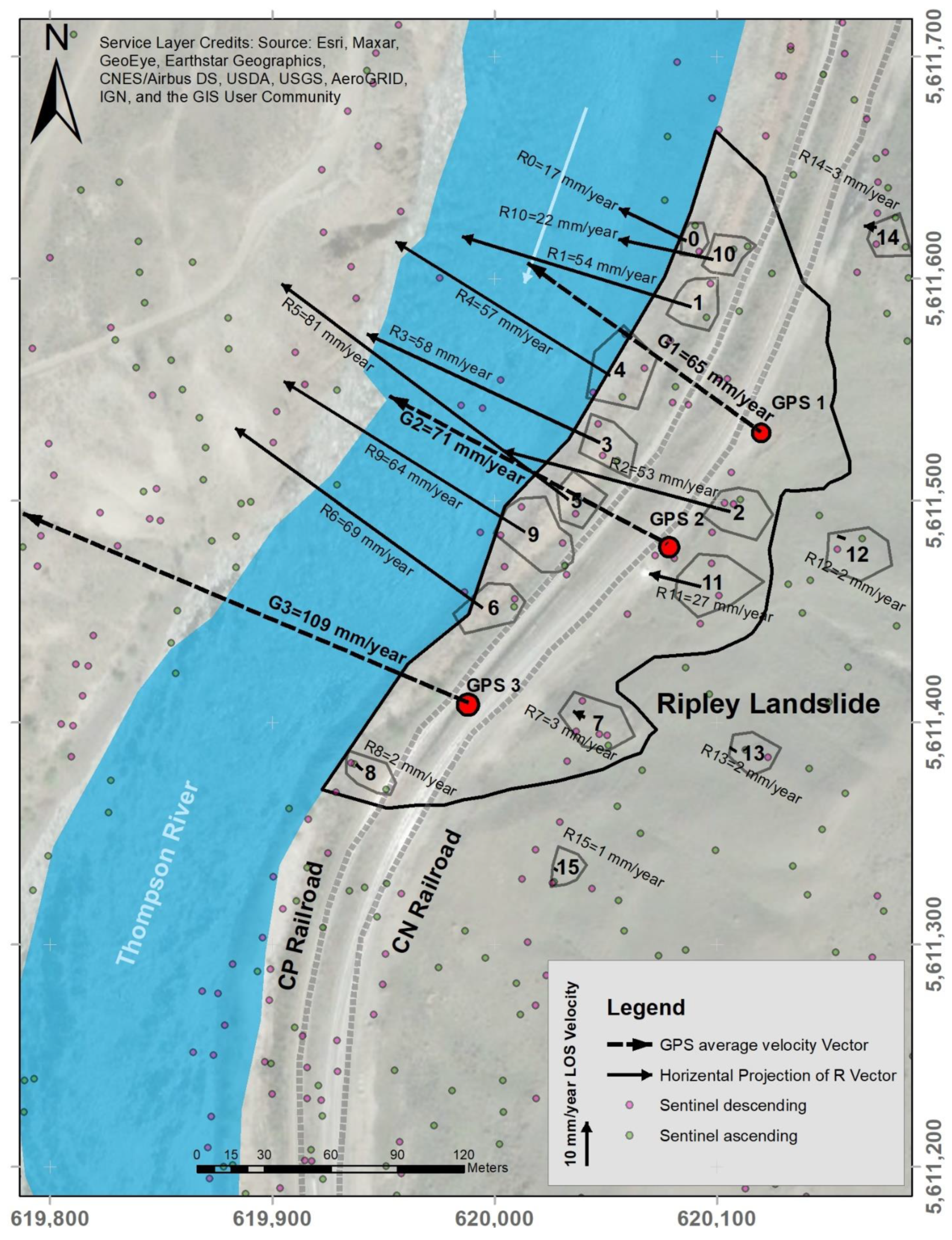
Figure 8 shows the plan view of the total horizontal component of the calculated R for the selected areas on the Ripley landslide. The satellite data used for calculating R correspond to the period between 26 May 2015 and 21 May 2017 for ascending orbit data and between 10 June 2015 and 12 May 2017 for descending orbit data to estimate annual displacement. The results are shown as average velocity of the real displacement vectors for each selected area in mm/year. Velocities are less than 3 mm/year behind the known back scarp and ranged between 12 and 53 mm/year at the back scarp within the landslide body, and up to 81 mm/year close to the river, which shows very slow to slow ground movement according to the velocity classification by [41,42]. These results are in agreement with the reported results by Huntely et al. [43], both in magnitudes and directions, which report displacements between 68 and 82 mm/year for different locations within the Ripley landslide body with the maximum ground movement occurring in the middle of the toe slide [43].
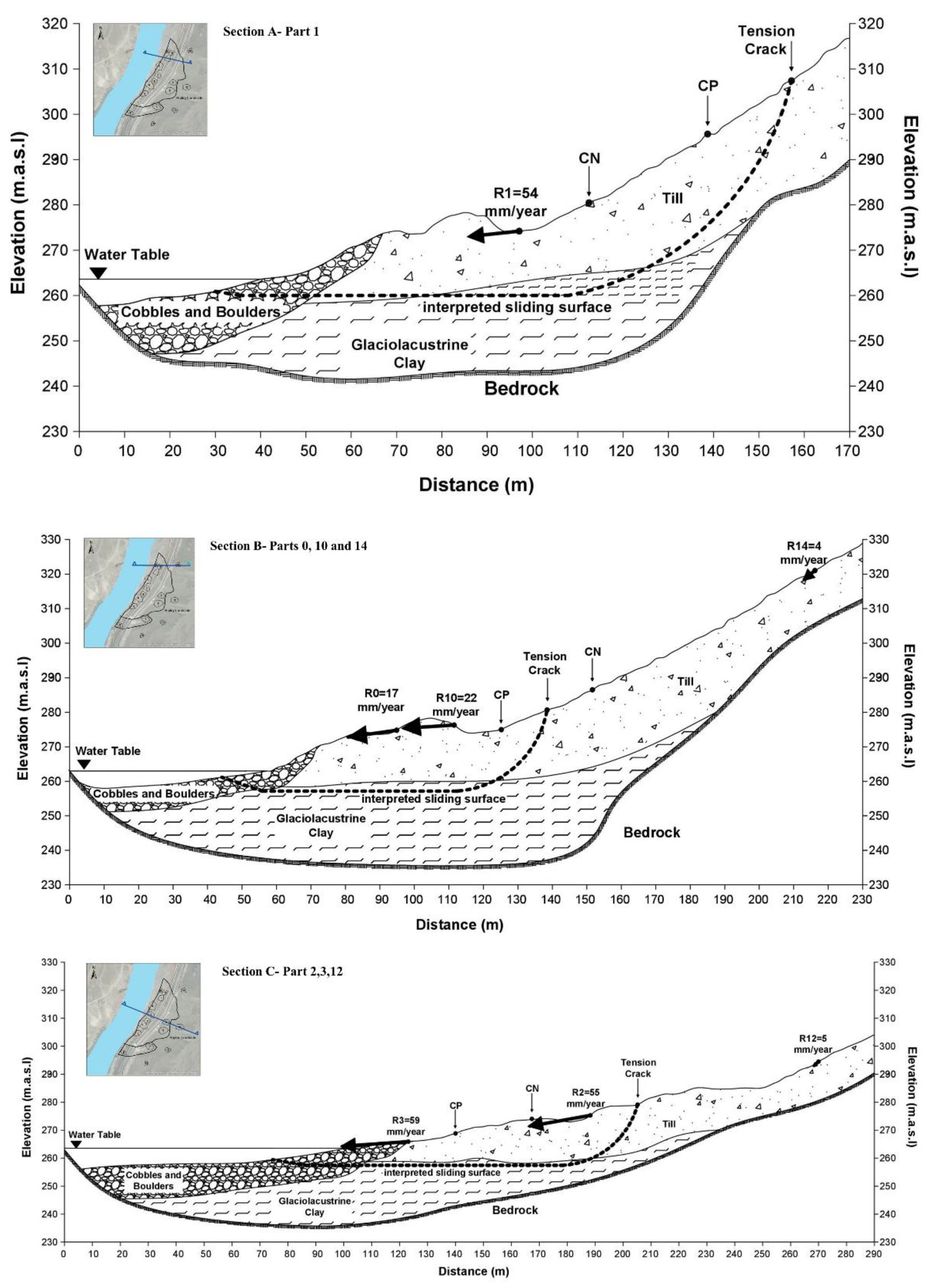
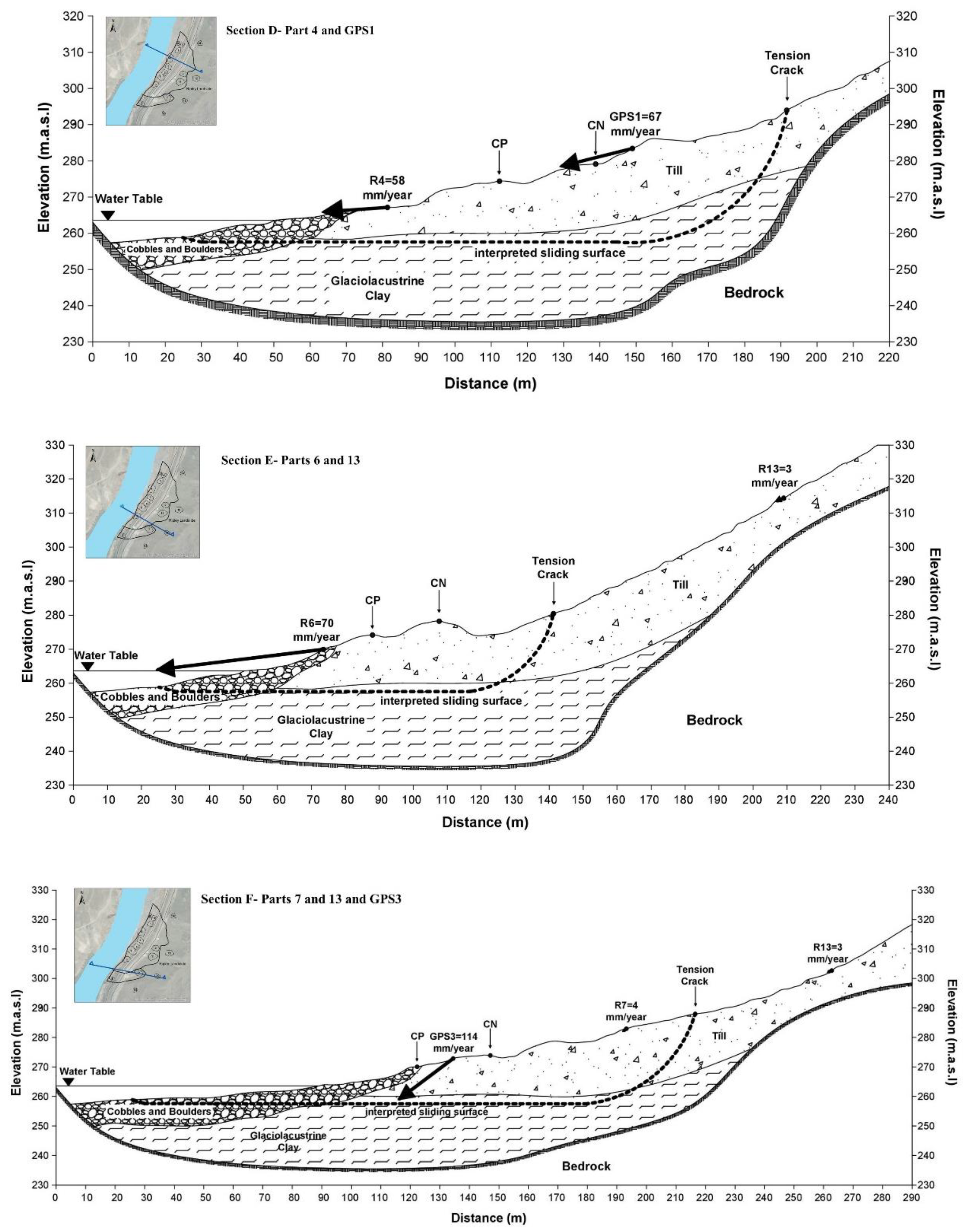
Figure 9 illustrates the ground movement velocities in section view on different cross-sections defined on the Ripley landslide. These sketched section views were inspired by previous research [14,18]. GPS average annual velocity vectors are also shown in the cross-sections intersecting the location of the GPS units. Table 3 presents the magnitudes of R, azimuth and horizontal angles (angle between R and the horizontal plane).

3.2. Comparison with in-Place Displacement Monitoring Instrumentation

Published GPS displacement results at the Ripley landslide were used to evaluate the validity of the estimated R.
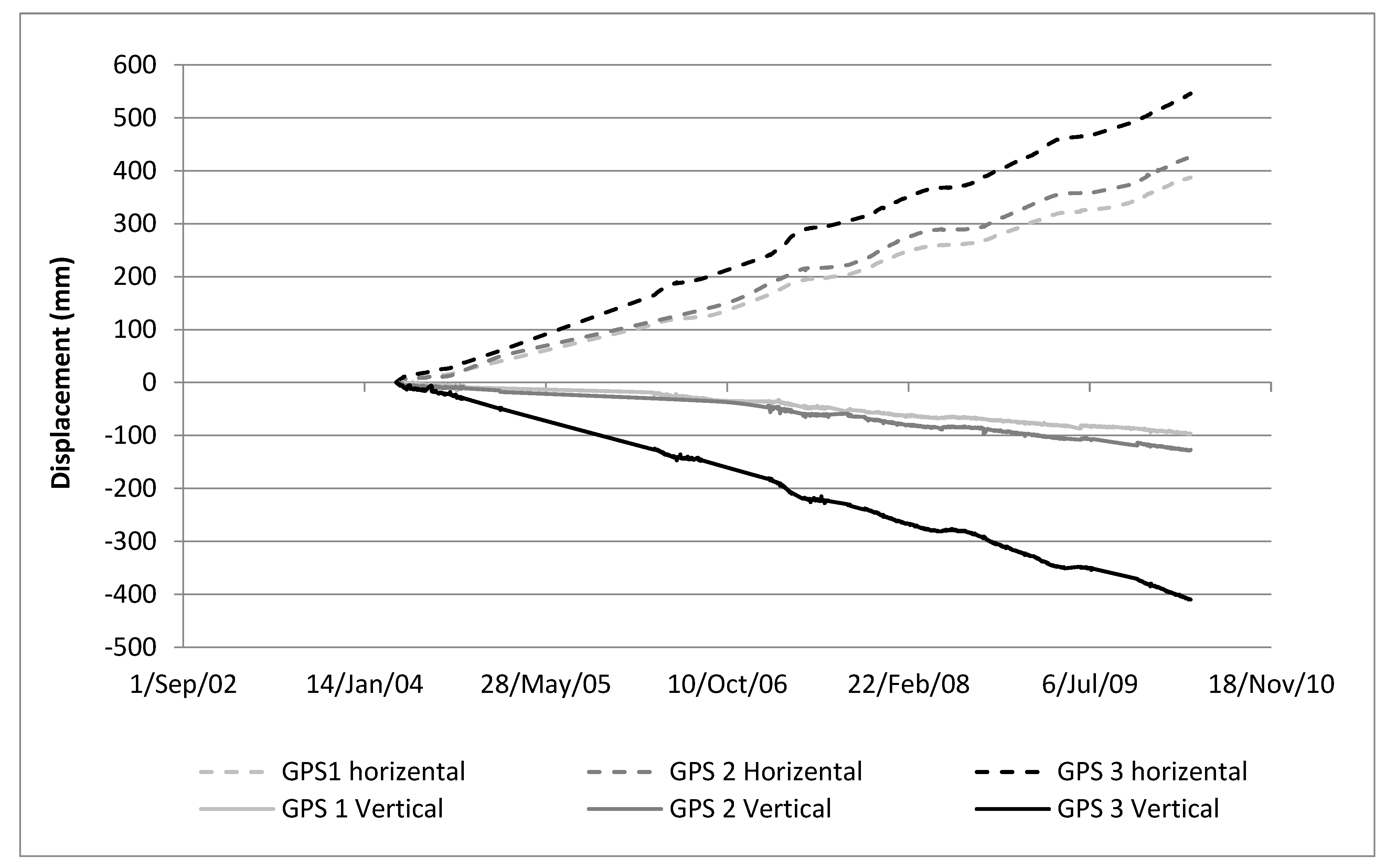
GPS data were selected between the installation day on 11 April 2008 and 11 April 2014. Annual results for the 6 years are averaged to get an estimated characteristic annual ground movement. In this regard, Macciotta et al. [15] showed that, in general, the acceleration and deceleration trend of the Ripley landslide measured by the GPS system was consistent for this period. The time series of GPS cumulative displacements in this period are presented as vertical and total horizontal components in Figure 10. Figure 11 shows each GPS horizontal displacement in plan-view together with the calculated R vectors. The summary of recorded displacement by each GPS is shown in Table 4. The GPS velocities in Table 4 are consistent with the calculated velocities for the R displacement vectors near the toe of the landslide.

4. Discussion

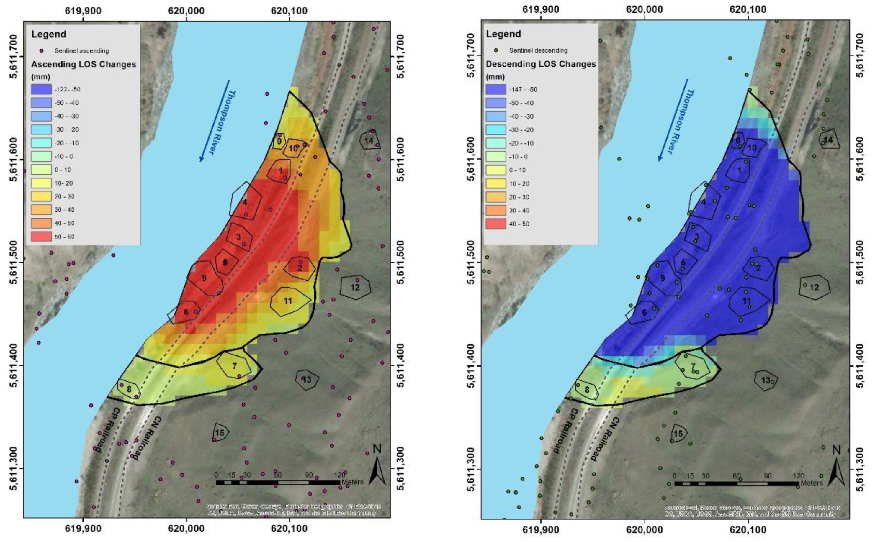
Figure 5 illustrated the scarcity of PS on the Ripley landslide from Sentinel ascending and descending orbits. Despite this low scatterer density, selected regions on the landslide did include scatterers for both satellite orientations so that an average R vector could be calculated. LOS results show faster deformations at the landslide’s toe and slowing towards the upper areas of the landslide. The LOS displacement for both satellite orientations is significantly lower outside the landslide extents to the north and south.
The fastest velocity was calculated in region 5 with 82 mm/year. This region is located near railway tracks on the center of the Ripley landslide as it is shown in Figure 8. The Ripley landslide is a very slow to slow moving landslide based on the velocity classification by [41,42]. Figure 7 indicates there are episodes in which the landslide is showing an accelerated rate of deformation as opposed to episodes in which the landslide moves slower. Although it is not as explicit as the seasonal trend of cumulative displacement of GPS data, which is shown in Figure 10, the cumulative LOS changes for both Sentinel ascending and descending satellites in Figure 7 introduces a faint trend in LOS changes that shows two acceleration seasons between October 2015 to May 2016 and November 2016 to the end of data, while they show deceleration between May 2016 and November 2016. This agrees with previous research that showed a correlation between ground movement and river water table fluctuation. Reductions in river flows (and drop in water head) has been associated with episodes on landslide acceleration [14,34]. The seasonal movement is more obvious for areas near the river, which showed more movement than other areas near the back scarp on the landslide body and also outside landslide boundaries. The inability of data to perform a strong trend can be referred to the relatively longer time intervals between InSAR readings for both satellites and seasonal impacts on InSAR results (e.g., vegetation growth, weather changes and ground moisture).
Calculated R vectors are in general good agreement with displacement measurements from GPS-1 and GPS-2 (Figure 10). The velocity for R4 is 58 mm/year with an azimuth of 302 degrees (Table 3), while the average velocity and azimuth angle are reported as 67 mm/year and 293 degrees, respectively, for GPS-1 in Table 4. For R5, the azimuth angle is 307 degrees (Table 3), which is consistent with GPS-2 in Table 4 (298 degrees), and the recorded ground displacement velocity by GPS-2 is 74 mm/year, compared to 82 mm/year for R5.
However, GPS-3 shows a faster landslide velocity and a larger vertical component as opposed to other locations near the track. Although there are no InSAR regions coincidental with GPS-3, this unit shows different displacement vector characteristics than the InSAR regions in the vicinity. It has been interpreted that the vertical movement of GPS-3 may be exaggerated because it is installed on a retaining structure that was built as part of track construction in 2005, and the weight of the structure over materials loosened by landslide deformations could lead to increased ground settlement [39].
Figure 8 shows that the magnitude of landslide displacements near the railway tracks and towards the river is significantly larger than deformations upslope, closer to the back scarp. It is illustrated in the cross sections in Figure 9 that the magnitude of R vectors tends to decrease with distance from the river; however, the vertical components of ground movement are greater at locations near the back scarp. Displacements near the railway tracks and closer to the river are predominantly sub-horizontal while the vertical component of calculated R vectors near the back scarp slightly increases in proportion to the total R magnitude. The magnitude of R vector velocities in Table 3 is between 17 and 82 mm/year and the angle with vertical plane is from 75 to 86 degrees near the landslide’s toe, while this angle is less than 60 degrees for the section near the back scarp. This would be consistent with the interpretation of the kinematics corresponding to a compound landslide, where a driving wedge in the upper section of the slope moves downslope pushing a passive wedge sliding over sub-horizontal shear surfaces. The vertical components of GPS displacements are also more notable than the vertical components of calculated R located on the landslide’s toe. The differences between displacement direction in section-view for GPS and InSAR results can be assigned to their different distances from the landslide’s back scarp.
Calculated R velocities were very small behind the back scarp of the landslide (between 2 and 5 mm/year). These values could suggest some initiation of movement behind the interpreted back scarp of the Ripley landslide; however, these small magnitudes could be within the limits of detection of the approach used, particularly when considering the assumptions required for the calculation of R. Any initiation of movement upslope from the known extents of the landslide could represent landslide retrogression, which is a common feature of most other landslides in the area. However, further monitoring would be required upslope from the known active area of the landslide to identify if retrogression of the landslide has initiated.

5. Conclusions

The Ripley landslide is a very slow moving landslide moving on a sub-horizontal weak clay layer. The landslide is located on an important transportation corridor in Canada along the Thompson River valley, and the two largest railway main lines traverse this landslide. This paper presents an update on the Ripley landslide displacement trends and kinematics using InSAR monitoring data. To obtain an improved understanding of InSAR displacement measurements, the landslide is divided into 12 areas that correspond to coverage from both Sentinel ascending and Sentinel descending orbits. A method is utilized where the horizontal component of movement is considered parallel to the slope azimuth to calculate the three-dimensional ground displacement vector. Ground displacement monitored with three GPS units on the landslide generally support the results from the method adopted.
Total InSAR LOS displacement velocities ranged between 2 mm/year and 82 mm/year, with faster sections near railroad tracks and the toe of the landslide, and slower sections at the back scarp of the landslide and upslope from the known active area. It is observed that landslide movement has a larger relative vertical component near the back scarp and becomes closer to horizontal direction near the railway tracks and near the toe. This would be consistent with the interpretation of the kinematics corresponding to a compound landslide, where a driving wedge in the upper section of the slope moves downslope pushing a passive wedge sliding over sub-horizontal shear surfaces.
Calculated ground velocities were very small behind the back scarp of the landslide (between 2 and 5 mm/year). These values could suggest some initiation of movement behind the interpreted back scarp of the Ripley landslide; however, these small magnitudes could be within the limits of detection of this approach, and further monitoring with in-situ instruments such as GPS, robotic total station and prisms to complement remote sensing techniques, e.g., satellite or ground-based InSAR, would be required upslope from the known active area of the landslide for identifying any potential landslide retrogression.

Author Contributions

Conceptualization, R.M. and A.S.; methodology, A.S.; software, A.S.; validation, A.S. and R.M.; formal analysis, A.S.; investigation, A.S.; resources, R.M.; data curation, A.S. and R.M.; writing—original draft preparation, A.S.; writing—review and editing, A.S. and R.M.; visualization, A.S.; supervision, R.M.; project administration, A.S.; funding acquisition, R.M. All authors have read and agreed to the published version of the manuscript.

Funding

This research is funded by the Natural Sciences and Engineering Research Council of Canada (NSERC), Canadian Pacific Railway, Canadian National Railway and Transport Canada and is a collaboration that incudes Queen’s University, the Canadian Geological Survey and the University of Alberta. The funding number for this research is ALLRP 549684-19.

Data Availability Statement

Not applicable.

Acknowledgments

The authors would like to acknowledge Canadian Pacific Railway (CP) and TRE Altamira for providing the InSAR monitoring results used in this study. This research was performed within the umbrella of the Railway Ground Hazards Research Program (RGHRP), which is funded by the Natural Sciences and Engineering Research Council of Canada (NSERC), Canadian Pacific Railway, Canadian National Railway, and Transport Canada and is a collaboration that incudes Queen’s University, the Canadian Geological Survey and the University of Alberta.

Conflicts of Interest

The authors declare they have no competing interest.

References

  1. Charrière, M.; Humair, F.; Froese, C.; Jaboyedoff, M.; Pedrazzini, A.; Longchamp, C. From the source area to the deposit: Collapse, fragmentation, and propagation of the Frank Slide. Geol. Soc. Am. Bull. 2020, 128, 332–351. [Google Scholar] [CrossRef]
  2. Cruden, D.M.; Martin, C.D. Before the Frank Slide. Can. Geotech. J. 2007, 44, 765–780. [Google Scholar] [CrossRef]
  3. Mei, S.; Poncos, V.; Froese, C. Mapping millimetre-scale ground deformation over the underground coal mines in the Frank Slide area, Alberta, Canada, using spaceborne InSAR technology. Can. J. Remote Sens. 2008, 34, 113–134. [Google Scholar] [CrossRef]
  4. Vallee, M. Falling in Place: Geoscience, Disaster, and Cultural Heritage at the Frank Slide, Canada’s Deadliest Rockslide. Space Cult. 2019, 22, 66–76. [Google Scholar] [CrossRef]
  5. Choe, B.-H.; Blais-Stevens, A.; Samsonov, S.; Dudley, J. Sentinel-1 and RADARSAT Constellation Mission InSAR Assessment of Slope Movements in the Southern Interior of British Columbia, Canada. Remote Sens. 2021, 13, 3999. [Google Scholar] [CrossRef]
  6. Huntley, D.; Bobrowsky, P.; Hendry, M.; Macciotta, R.; Best, M. Multi-technique Geophysical Investigation of a Very Slow-moving Landslide near Ashcroft, British Columbia, Canada. J. Environ. Eng. Geophys. 2019, 24, 87–110. [Google Scholar] [CrossRef]
  7. Rodriguez, J.; Macciotta, R.; Hendry, M.T.; Roustaei, M.; Gräpel, C.; Skirrow, R. UAVs for monitoring, investigation, and mitigation design of a rock slope with multiple failure mechanisms—A case study. Landslides 2020, 17, 2027–2040. [Google Scholar] [CrossRef]
  8. Deane, E.; Macciotta, R.; Hendry, M.; Grapel, C.; Skirrow, R. Leveraging historical aerial photographs and digital photo-grammetry techniques for landslide investigation—A practical perspective. Landslides 2020, 17, 1989–1996. [Google Scholar] [CrossRef]
  9. Macciotta, R.; Gräpel, C.; Skirrow, R. Fragmented Rockfall Volume Distribution from Photogrammetry-Based Structural Mapping and Discrete Fracture Networks. Appl. Sci. 2020, 10, 6977. [Google Scholar] [CrossRef]
  10. Woods, A.; Macciotta, R.; Hendry, M.; Stewart, T.; Marsh, J. Updated understanding of the deformation characteristics of the Checkerboard Creek rock slope through GB-InSAR monitoring. Eng. Geol. 2020, 281, 105974. [Google Scholar] [CrossRef]
  11. Lan, H.; Zhao, X.; Macciotta, R.; Peng, J.; Li, L.; Wu, Y.; Zhu, Y.; Liu, X.; Zhang, N.; Liu, S.; et al. The cyclic expansion and contraction characteristics of a loess slope and implications for slope stability. Sci. Rep. 2021, 11, 2250. [Google Scholar] [CrossRef] [PubMed]
  12. Rodriguez, J.; Deane, E.; Hendry, M.; Macciotta, R.; Evans, T.; Gräpel, C.; Skirrow, R. Practical evaluation of single-frequency dGNSS for monitoring slow-moving landslides. Landslides 2021, 18, 3671–3684. [Google Scholar]
  13. Macciotta, R.; Hendry, M.T. Remote Sensing Applications for Landslide Monitoring and Investigation in Western Canada. Remote Sens. 2021, 13, 366. [Google Scholar] [CrossRef]
  14. Hendry, M.T.; Macciotta, R.; Martin, C.D.; Reich, B. Effect of Thompson River elevation on velocity and instability of Ripley Slide. Can. Geotech. J. 2015, 52, 257–267. [Google Scholar] [CrossRef]
  15. Macciotta, R.; Hendry, M.; Martin, C.D. Developing an early warning system for a very slow landslide based on displacement monitoring. Nat. Hazards 2015, 81, 887–907. [Google Scholar] [CrossRef]
  16. Journault, J.; Macciotta, R.; Hendry, M.T.; Charbonneau, F.; Huntley, D.; Bobrowsky, P.T. Measuring displacements of the Thompson River valley landslides, south of Ashcroft, BC, Canada, using satellite InSAR. Landslides 2018, 15, 621–636. [Google Scholar] [CrossRef]
  17. Huntley, D.; Bobrowsky, P.; Hendry, M.; Macciotta, R.; Elwood, D.; Sattler, K.; Best, M.; Chambers, J.; Meldrum, P. Application of multi-dimensional electrical resistivity tomography datasets to investigate a very slow-moving landslide near Ash-croft, British Columbia, Canada. Landslides 2019, 16, 1033–1042. [Google Scholar] [CrossRef]
  18. Schafer, M. Kinematics and Controlling Mechanics of the Slow Moving Ripley Landslide. Master’s Thesis, University of Alberta, Edmonton, AL, Canada, 2016. [Google Scholar]
  19. Huntley, D.; Holmes, J.; Bobrowsky, P.; Chambers, J.; Meldrum, P.; Wilkinson, P.; Donohue, S.; Elwood, D.; Sattler, K.; Hendry, M.; et al. Hydrogeological and geophysical properties of the very slow-moving Ripley Landslide, Thompson River valley, British Columbia. Can. J. Earth Sci. 2020, 57, 1371–1391. [Google Scholar] [CrossRef]
  20. Xu, D.; Hu, X.-Y.; Shan, C.-L.; Li, R.-H. Landslide monitoring in southwestern China via time-lapse electrical resistivity tomography. Appl. Geophys. 2016, 13, 1–12. [Google Scholar] [CrossRef]
  21. Herrera, G.; Gutierrez, F.; Garcia-Davalilo, J.C.; Guerrero, J.; Notti, D.; Galve, J.P.; Fernandez-Merodo, J.A.; Cooksley, G. Multi-sensor advanced DInSAR monitoring of very slow landslides: The Tena Valley case study (Central Spanish Pyrenees). Remote Sens. Environ. 2012, 381–387, 08037. [Google Scholar]
  22. Colesanti, C.; Wasowski, J. Investigating landslides with space-borne Synthetic Aperture Radar (SAR) interferometry. Eng. Geol. 2006, 88, 173–199. [Google Scholar] [CrossRef]
  23. Vadivel, S.K.P.; Kim, D.J.; Kim, Y.C. Time-series InSAR Analysis and post-processing Using ISCE-StaMPS package for Meas-uring Bridge Displacements. Korean J. Remote Sens. 2020, 36, 527–534. [Google Scholar]
  24. Abe, T.; Iwahana, G.; Efremov, P.V.; Desyatkin, A.R.; Kawamura, T.; Fedorov, A.; Zhegusov, Y.; Yanagiya, K.; Tadono, T. Surface displacement revealed by L-band InSAR analysis in the Mayya area, Central Yakutia, underlain by continuous permafrost. Earth Planets Space 2020, 72, 138. [Google Scholar] [CrossRef]
  25. Motagh, M.; Shamshiri, R.; Haghighi, M.H.; Wetzel, H.-U.; Akbari, B.; Nahavandchi, H.; Roessner, S.; Arabi, S. Quantifying groundwater exploitation induced subsidence in the Rafsanjan plain, southeastern Iran, using InSAR time-series and in situ measurements. Eng. Geol. 2017, 218, 134–151. [Google Scholar] [CrossRef]
  26. Hooper, A.; Bekaert, D.; Spaans, K.; Arıkan, M. Recent advances in SAR interferometry time series analysis for measuring crustal deformation. Tectonophysics 2012, 514–517, 1–13. [Google Scholar] [CrossRef]
  27. Chen, B.; Li, Z.; Zhang, C.; Ding, M.; Zhu, W.; Zhang, S.; Han, B.; Du, J.; Cao, Y.; Zhang, C.; et al. Wide Area Detection and Distribution Characteristics of Landslides along Sichuan Expressways. Remote Sens. 2022, 14, 3431. [Google Scholar] [CrossRef]
  28. Liu, Y.; Yao, X.; Gu, Z.; Zhou, Z.; Liu, X.; Chen, X.; Wei, S. Study of the Automatic Recognition of Landslides by Using InSAR Images and the Improved Mask R-CNN Model in the Eastern Tibet Plateau. Remote Sens. 2022, 14, 3362. [Google Scholar] [CrossRef]
  29. Mastro, P.; Masiello, G.; Serio, C.; Pepe, A. Change Detection Techniques with Synthetic Aperture Radar Images Experimens with Random Forests and Sentinel-1 Observations. Remote Sens. 2022, 14, 3323. [Google Scholar] [CrossRef]
  30. Abdel-Hamid, A.; Dubovyk, O.; Greve, K. The potential of sentinel-1 InSAR coherence for grasslands monitoring in Eastern Cape, South Africa. Int. J. Appl. Earth Obs. Geoinf. 2021, 98, 102306. [Google Scholar] [CrossRef]
  31. Dumka, K.R.; SuriBabu, D.; Malik, K.; Prajapati, S.; Narain, P. PS-InSAR derived deformation study in the Kachchh, Western India. Appl. Comput. Geosci. 2020, 8, 100041. [Google Scholar] [CrossRef]
  32. Castellazzi, P.; Schmid, W. Interpreting C-band InSAR ground deformation data for large-scale groundwater management in Australia. J. Hydrol. Reg. Stud. 2020, 34, 100774. [Google Scholar] [CrossRef]
  33. Mancini, F.; Grassi, F.; Cenni, N. A Workflow Based on SNAP–StaMPS Open-Source Tools and GNSS Data for PSI-Based Ground Deformation Using Dual-Orbit Sentinel-1 Data: Accuracy Assessment with Error Propagation Analysis. Remote Sens. 2021, 13, 753. [Google Scholar] [CrossRef]
  34. Huntley, D.; Rotheram-Clarke, D.; Pon, A.; Tomaszewicz, A.; Leighton, J.; Cocking, R.; Joseph, J. Benchmarked RADARSAT-2, SENTINEL-1 and RADARSAT Constellation Mission Change-Detection Monitoring at North Slide, Thompson River Valley, British Columbia: Ensuring a Landslide-Resilient National Railway Network. Can. J. Remote Sens. 2021, 47, 635–656. [Google Scholar] [CrossRef]
  35. Clague, J.J.; Evans, S.G. Geologic Framework of Large Historic Landslides in Thompson River Valley, British Columbia. Environ. Eng. Geosci. 2003, 9, 201–212. [Google Scholar] [CrossRef]
  36. Huntley, D.H.; Bobrowsky, P.T. Surficial geology and monitoring of the Ripley Slide, near Ashcroft, British Columbia, Canada. Geol. Surv. Can. 2014, 7531, 21. [Google Scholar] [CrossRef]
  37. Porter, M.J.; Savigny, K.W.; Keegan, T.R.; Bunce, C.M.; MacKay, C. Controls on stability of the Thompson River landslides. In Proceedings of the 55th Canadian Geotechnical Conference, Niagara Falls, ON, Canada, 20–23 October 2002. [Google Scholar]
  38. Eshraghian, A.; Martin, C.D.; Cruden, D.M. Complex Earth Slides in the Thompson River Valley, Ashcroft, British Columbia. Environ. Eng. Geosci. 2007, 13, 161–181. [Google Scholar] [CrossRef]
  39. Macciotta, R.; Hendry, M.; Martin, D.; Eldwood, E.; Lan, H.; Huntley, D.; Bobrowsky, P.; Sladen, W.; Bunce, C.; Choi, E.; et al. Monitoring of the Ripley Slide in the Thompson River Valley, BC. In Proceedings of the Geohazards 6—6th Canadian Geohazards Conference, Kingston, ON, Canada, 15–18 June 2014. [Google Scholar] [CrossRef]
  40. Sattler, K.; Elwood, D.; Hendry, M.T.; Huntley, D.; Holmes, J.; Wilkinson, P.B.; Chambers, J.; Donohue, S.; Meldrum, P.I.; Macciotta, R.; et al. Quantifying the contribution of matric suction on changes in stability and displacement rate of a translational landslide in glaciolacustrine clay. Landslides 2021, 18, 1675–1689. [Google Scholar] [CrossRef]
  41. Cruden, D.M.; Varnes, D.J. Landslide Types and Processes, Transportation Research Board; U.S. National Academy of Sciences, Special Report, 247; National Academy of Sciences: Washington, DC, USA, 1996. [Google Scholar]
  42. Hungr, O.; Leroueil, S.; Picarelli, L. The Varnes classification of landslide types, an update. Landslides 2014, 11, 167–194. [Google Scholar] [CrossRef]
  43. Huntley, D.; Rotheram-Clarke, D.; Cocking, R.; Joseph, J.; Bobrowsky, P. Understanding Plateau and Prairie Landslides: Annual Report on Landslide Research in the Thompson River Valley, British Columbia, and the Assiniboine River Valley, Manitoba-Saskatchewan 2020–2021 to 2021–2022; Geological Survey of Canada: Ottawa, ON, USA, 2021.
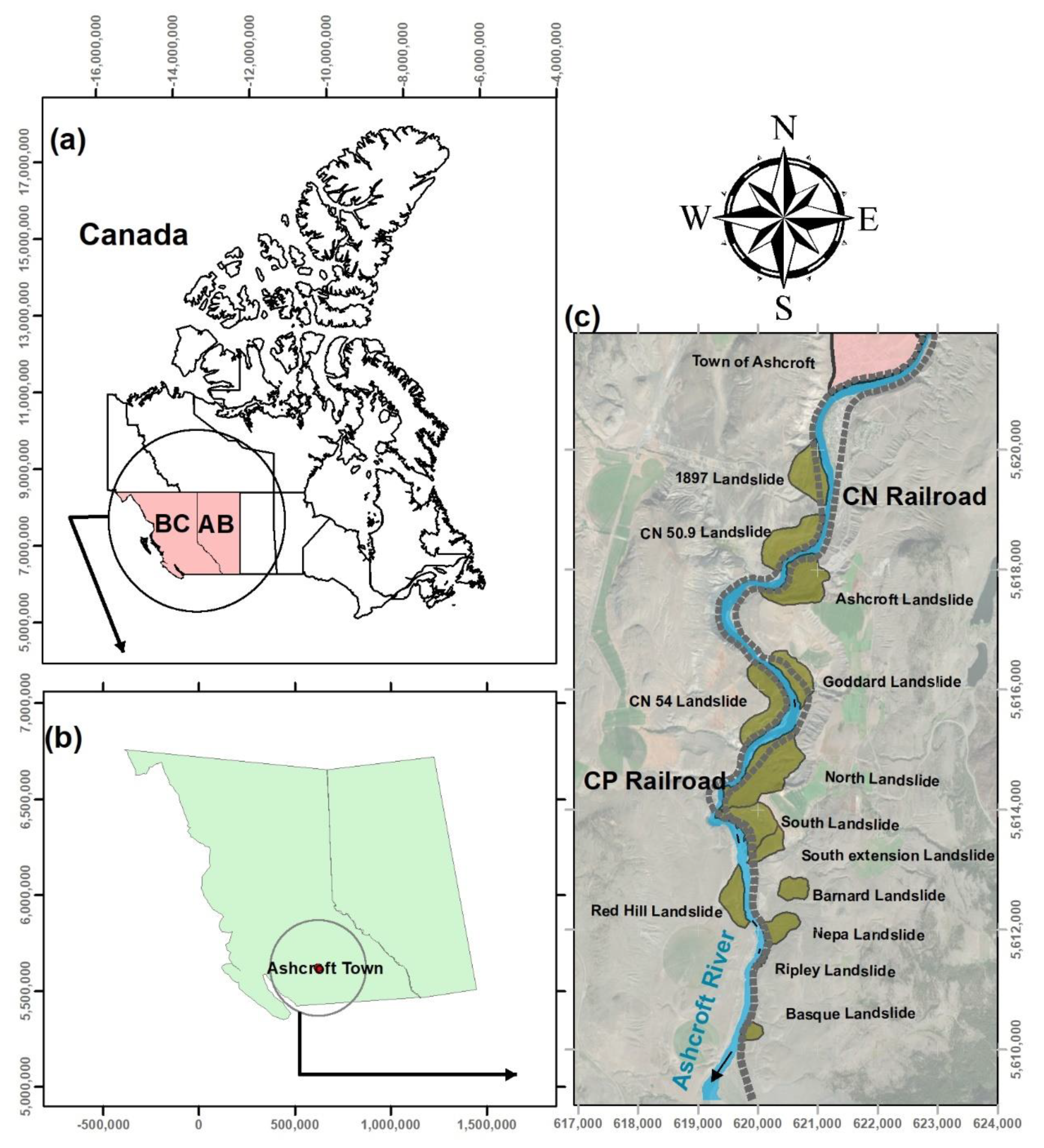
Figure 1. Thompson River valley location (a,b) plan-view and active landslides across the valley (c). Coordinates in UTM (units in meters for scale purposes). BC and AB in (a) correspond to the provinces of British Columbia and Alberta, respectively.
Geosciences 12 00298 g001
Figure 2. Ripley slide geometry including CN and CP railways and installed GPS on the site.
Geosciences 12 00298 g002
Figure 3. Location of installed GPS systems on Ripley landslide.
Geosciences 12 00298 g003
Figure 4. Geometry of the image acquisitions along the ascending (a) and descending (b) orbits (inspired by ground deformation InSAR analysis over the Thompson Canyon, British Columbia, Technical Details, August 2018, by TRE Group).
Geosciences 12 00298 g004
Figure 5. InSAR data coverage for both Sentinel ascending and descending orbits on the Ripley landslide and areas selected for analysis (containing LOS changes during the selected time frame).
Geosciences 12 00298 g005
Figure 6. LOS vectors projected on the horizontal plane for both Sentinel ascending and Sentinel descending orbits. The average direction of the slope azimuth is also shown.
Geosciences 12 00298 g006
Figure 7. Average cumulative LOS displacement for both Sentinel ascending and Sentinel descending orbits for specific areas within the Ripley landslide (SA for Sentinel ascending and SD for Sentinel descending). (a) SA 0,1,5,6,7,8,10,11 and SD 7,8,10—(b) SA 2,3,4,9,12,13,14,15 and SD 12,13,14,15—(c) SD 2,3,4,9—(d) SD 0,1,5,6,11.
Geosciences 12 00298 g007aGeosciences 12 00298 g007b
Figure 8. Calculated total horizontal component of deformation (R) in plan-view on Ripley landslide.
Geosciences 12 00298 g008
Figure 9. Real vectors (ground movement) in section view on Ripley landslide (sliding surfaces are drawn based on the position of tension tracks and interpreted shear surface by Hendry et al. [14] based on previous BH and SAA installation).
Geosciences 12 00298 g009aGeosciences 12 00298 g009bGeosciences 12 00298 g009c
Figure 10. Cumulative horizontal and vertical displacements of installed GPS systems on Ripley landslide.
Geosciences 12 00298 g010
Figure 11. R vectors and GPS average velocity vectors (mm/y) in plan-view.
Geosciences 12 00298 g011
Table 1. Details of the processed satellite InSAR data.
Radar Data Information
SatelliteSentinel 1Sentinel 1
Acquisition GeometryAscendingDescending
Period Covered by Imagery3 November 2014 to
17 March 2018
6 November 2014 to
1 April 2018
No. of Processed Images5159
Coordinate SystemWGS 1984WGS 1984
Area of Interest 869.2   Km 2 869.2   Km 2
Number of PS + DS194,083 (112,343 PS, 81,740 DS)178,396 (89,510 PS, 88,886 DS)
Sensor ModeIWIW
Image Resolution20 m × 5 m20 m × 5 m
Table 2. Satellite viewing (LOS) angles for the Sentinel and Radarsat-2 imagery.
SatelliteOrbit GeometryTrackSensor ModeSymbolAngle
(Degree)
SentinelAscending64IWθ
δ
38.66
11.33
SentinelDescending115IWθ
δ
44.29
7.79
Table 3. Magnitudes of R and direction.
AreaRecorded DateTotal Magnitude (mm/Year)Horizontal Component (mm/Year)Westward Magnitude (mm/Year)Northward Magnitude (mm/Year)Downward Magnitude (mm/Year)Azimuth Angle (Degree)Angle with Horizontal Plane (Degree)
R0May 2015
to
May 2017
171715722968
R1May 2015
to
May 2017
5454521662876
R2May 2015
to
May 2017
555351141428515
R3May 2015
to
May 2017
5958532542954
R4May 2015
to
May 2017
5857493043024
R5May 2015
to
May 2017
828165491330711
R6May 2015
to
May 2017
7069564173067
R7May 2015
to
May 2017
4321329737
R8May 2015
to
May 2017
2211031310
R9May 2015
to
May 2017
656455341130211
R10May 2015
to
May 2017
222222512824
R11May 2015
to
May 2017
34121133228443
R12May 2015
to
May 2017
5221428743
R13May 2015
to
May 2017
3221130324
R14May 2015
to
May 2017
4330227730
R15May 2015
to
May 2017
2111129535
Table 4. Movement Records of Installed GPS on Ripley Slide.
GPS
Name
Recorded
Dates
Westward
Movement
(mm)
Northward
Movement
(mm)
Downward
Movement
(mm)
Total
Movement
(mm)
Horizontal
Movement
(mm)
Angle
with
Horizontal Plane
(Degree)
Azimuth
Angle
(Degree)
Average
Velocity
(mm/year)
GPS111-Apr-08
to
11-Apr-14
355154973993871429367
GPS211-Apr-08
to
11-Apr-14
3771991274454261729874
GPS311-Apr-08
to
11-Apr-14
44331941068354637306114
Publisher’s Note: MDPI stays neutral with regard to jurisdictional claims in published maps and institutional affiliations.