Article

Stabilization of the Lower Jamuna River in Bangladesh—Hydraulic and Morphological Assessment

1
Inland Water System Unit, Deltares, 2600 MH Delft, The Netherlands
2
Northwest Hydraulic Consultants, Edmonton, AB T6X 0E3, Canada
3
Deltares Software Centre, Deltares, 2600 MH Delft, The Netherlands
4
Hydraulic Engineering Department, Delft University of Technology, 2600 GA Delft, The Netherlands
5
Bangladesh Water Development Board, Dhaka 1205, Bangladesh
*
Author to whom correspondence should be addressed.
Geosciences 2021, 11(9), 389; https://doi.org/10.3390/geosciences11090389
Submission received: 20 July 2021 / Revised: 3 September 2021 / Accepted: 8 September 2021 / Published: 14 September 2021
(This article belongs to the Special Issue Recent Advances on Sediment Transport and River Morphodynamics)

Abstract

:
This paper presents a hydraulic and morphological analysis of the Lower Jamuna in Bangladesh with a focus on two key bifurcations that are important for stabilization of the Lower Jamuna reach. We used ground measurements, historical data, multispectral satellite images from various sources as well as numerical models. We carried out hydraulic analyses of the changes and their peculiarities, such as flow distributions at the bifurcation and hysteresis of the stage–discharge relationships. We supplemented our analysis by using numerical models to simulate discharge distribution at the bifurcations under various flow and riverbed conditions. We developed an advanced and automated satellite image processing application for the Lower Jamuna, referred to as Morphology Monitor (MoMo), using the Google Earth Engine. MoMo was found to be an effective tool for a rapid assessment and analysis of the changes in deep-channel and sandbar areas. It is also useful for monitoring and assessing riverbank and char erosion and accretion, which is important not only for morphological but also ecological impact assessment. The application can be adapted as an operational tool as well. Furthermore, we assessed the evolution of deep channels at the bifurcations based on regularly and extensively measured bathymetry data. The analysis was carried out in complement with morphological modeling, particularly for short-term prediction. In this paper we present the major findings of the analysis and discuss their implications for adaptive river management.

1. Introduction

1.1. Background

The Brahmaputra River flows from the Himalayas through China, India and finally Bangladesh, before eventually debouching into the Bay of Bengal (Figure 1). The last 250 km of the reach in Bangladesh are referred to as the Jamuna. The banks of the Jamuna River are primarily composed of easily erodible loose, unconsolidated sandy soil, which, combined with the region’s powerful monsoon floods, causes large-scale devastation in this country with a population density of over 1200 people per square kilometer. It is estimated that erosion has displaced around 2.2 million people along the Jamuna and Padma rivers since the 1970s [1]. Additionally, unstable riverbanks can erode embankments, causing breaches and severe flooding.
The Flood and Riverbank Erosion Risk Management Investment Program (FRERMIP), funded by the Asian Development Bank [2], aims to stabilize the region’s major rivers through adaptive river management. As part of the stabilization efforts the program also intends to reclaim land from the river that increased its width by 50% since 1970. The program primarily depends on long, guiding revetments to protect eroding outer bends. These “bend control” structures are intended to work together to stabilize the channels, while at the same time leaving inner bends natural for ecological and economic considerations. By choosing opportune moments to construct the riverbank protection structures, closure dams, etc., the Bangladeshi people can work with the river to obtain a more stable environment. In turn, this will enable both social and economic development for the communities that live in the vicinity of the river. To support this stabilization, the study presented in this paper is a component of the FRERMIP, aimed at gaining a better understanding of the hydraulic and morphological features of the Lower Jamuna. The focus of this study is mainly on the bifurcations, i.e., the major bifurcation at about 17 km downstream of the Bangabandhu (Jamuna) Bridge and the Salimabad bifurcation (Figure 1), since understanding their hydraulic and morphodynamic behavior is important for river stabilization and adaptation plans.

1.2. Study Area

The Jamuna River is one of the largest sand-bed braided rivers in the world, with bankfull discharges estimated to be around 45,000 m³/s [3]. This study is focused on the Lower Jamuna, located between the Bangabandhu (Jamuna) Bridge and the Ganges confluence (Figure 1). The reach is approximately 60 km long, and contains the intake of the Hurasagar River and multiple offtakes of the Dhaleshwari River system. Approximately 17 km downstream of the Jamuna Bridge, the river bifurcates into two major anabranches. Desired stabilization measures within this reach include stabilization of the sediment and flow distribution at this bifurcation, reduction in bank erosion, as well as the closure of the Salimabad channel to enable land reclamation.

1.3. Literature Review

Rennell [4] carried out the earliest study of the Brahmaputra, mapping it as a braided river. The pioneering studies by Coleman [5] and Latif [6] include detailed analyses of channel processes and sediment transport in the Brahmaputra River. Coleman [5] reported that the most significant bankline migration occurs during the falling stages of the flood, when excess sediment is deposited as bars within the channel, causing flow redirection. In 1969 Latif [6] reported on how the river has widened at an average rate of 36 m or 0.49% per year over the previous 133 years. Bristow [7] monitored channel patterns and migration using satellite images and historical maps. After two successive record floods occurred in 1987 and 1988, a systematic study of the Jamuna was conducted in the 1990s within the Flood Action Plan [8,9]. During the Flood Action Plan various river training techniques were piloted and systematic monitoring of the river was realized. Erosion prediction tools were developed as well. Effective river stabilization began in the early 2000s, once cost-effective geobag revetments were developed [10]. The Center for Environmental and Geographic Information Services (CEGIS) furthered the erosion prediction tools of the Flood Action Plan [11,12,13]. The CEGIS studied bifurcations in the Jamuna River, including how downstream anabranch angles impact bifurcation dynamics [14], building upon earlier works dedicated to prediction of changes in the Jamuna River using deterministic, stochastic and statistical models as well as the problems with their predictability ([15,16,17,18] among others).
An important aspect of our study is related to hydraulic and morphological stability of a major bifurcation as well as branches at the Lower Jamuna. Several previous general studies provide us with fundamental insights into hydraulic and morphodynamic behavior of large rivers [19,20,21] and bifurcations, as well as guidelines for (quasi) stable bifurcations, anabranches and distributary offtakes. Using numerical modeling, Kleinhans et al. [22] found that bifurcation dynamics are dominated by gradient differences, upstream bends, width-to-depth ratios of the upstream approach channel (which determines the bar pattern), sediment sorting, local bank irregularities, bank erosion and accretion as well as scour holes or vortex bars just downstream from the bifurcation. Their model tests concluded that counteracting effects, such as an upstream bend and a downstream gradient, can offset one another and create a stable bifurcation. One of the main conclusions was that the transverse slope at a bifurcation can influence the sediment division because the gravitational effects can counteract the shear stress resulting from the flow velocities. Their study looked at a meandering, 500-m-wide channel; this effect does not play a large role in rivers with large width-to-depth ratios, such as the Jamuna [23].
Edmonds and Slingerland [24] addressed why asymmetrical bifurcations are more common in nature. The numerical modeling results found that, in a fine-grained cohesive bifurcation, the dominant mechanism of sediment division between the downstream branches is the variation in bed levels, causing non-uniform surface elevation at the entrance of the two branch channels. This study urged that asymmetrical bifurcations were more common in nature because perturbations, such as alternating side bars, river meandering, floods or planform advantages, cause asymmetry between the branches. Once a bifurcation becomes asymmetrical, the non-uniform water surface topography and the effect of the bed ramp on the flow field provide feedbacks that keep asymmetrical bifurcations dynamically stable. Schuurman and Kleinhans [25] used schematic models to study the evolution of bar dynamics and bifurcations in braided sand-bed rivers. They found that crossbar channelization, caused by water level differences between parallel branches, was the most frequent cause of the instigation of bifurcations. Furthermore, the study found that bifurcation closure was not dominated by one specific process. Bar movement was determined to have a notable influence on branch closure, particularly bar-tail limb expansion in minor branches and bar merging. The numerical simulations confirmed the finding of the CEGIS that bar-tail limbs are useful for predicting where the dominant flow occurs as well as predicting angle asymmetry that may lead to the closure of a branch. Lama and Kuroki [26] combined experimental and numerical investigations to assess the effect of alternating bars in the approach channel. The study showed that a pool zone in front of a branch entrance increased the quantity of sediment entering into the branch as opposed to a shallower area. More recently, Mosselman and Crosato [27] studied bar dynamics in alluvial rivers. These studies, except for Schuurman and Kleinhans [25], looked at bifurcations found in narrow, meandering rivers, as opposed to wide, shallow bifurcations found in a dynamic sand-bed braided river such as the Lower Jamuna. Giri et al. [28] demonstrate the importance of detecting deep-channel dynamics for large rivers. The present paper presents the application of various methods and tools to assess and analyze a complex real-world problem associated with the stabilization of the Lower Jamuna with a major bifurcation.

1.4. Objective of This Paper

The main objective of this paper is to present our observations and findings of the spatial and temporal variations in the hydraulic and morphological features of the Lower Jamuna with a focus on the major bifurcation and the Salimabad bifurcation. This paper outlines how various tools and data, including ground measurements, advanced satellite imagery analysis and numerical computations, were used to better understand the morphology of the Lower Jamuna. We include a discussion of our findings regarding: (i) hydraulic analysis of discharges and water levels including hysteresis effect at the Lower Jamuna, (ii) discharge distributions at the major bifurcation and the Salimabad bifurcation in addition to (iii) morphological changes, including deep-channel evolution and migration, revealing their importance for erosion management.

2. Hydraulic Analysis

2.1. Methodology

2.1.1. Ground Measurement

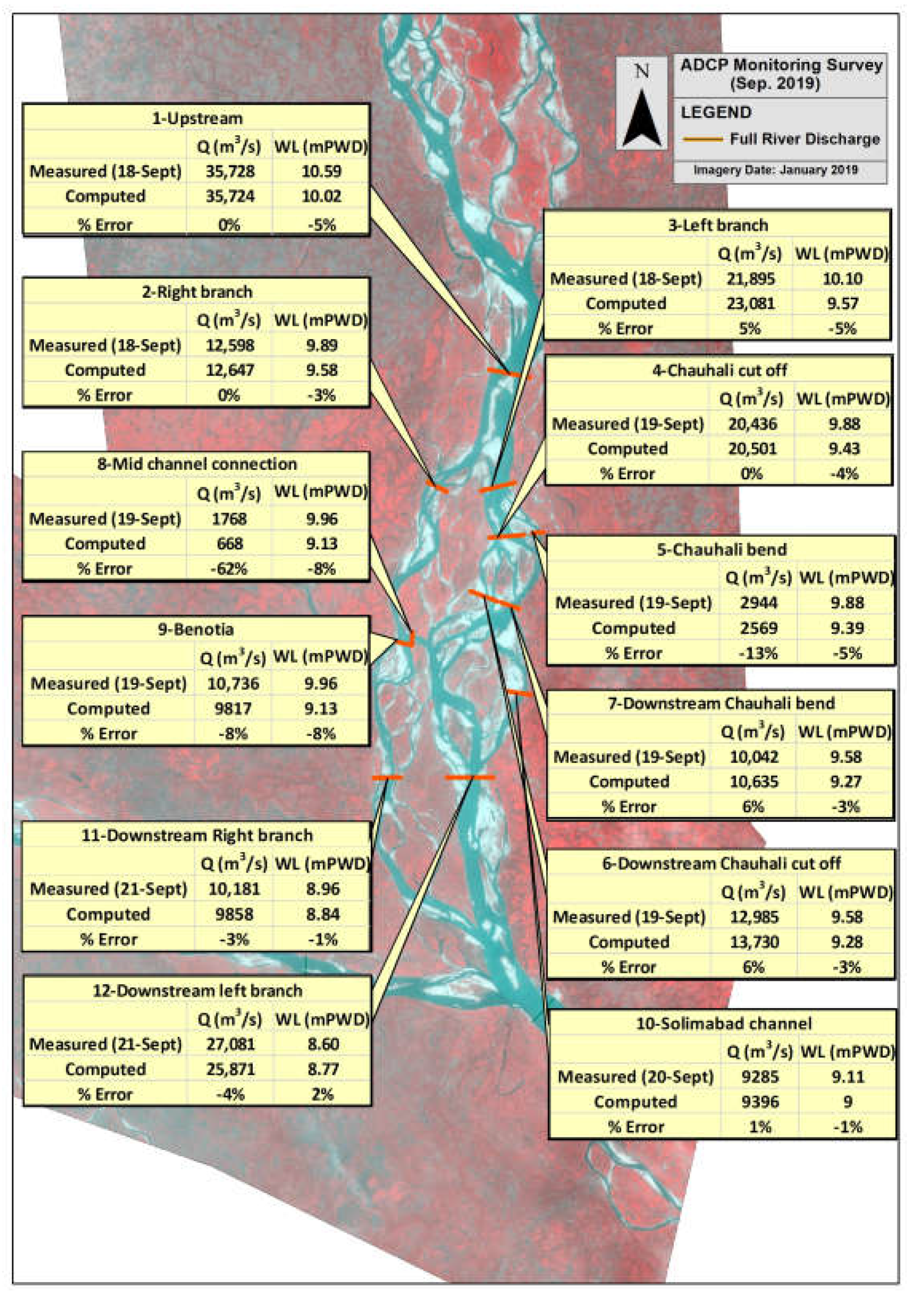
In 2016–2019, acoustic Doppler current profiler (ADCP) data were collected in multiple channels of the Lower Jamuna (as shown in Figure 2). Instantaneous discharges and water levels were measured at various branches. The discharges at the main branches were measured in earlier years as well, but they were not measured regularly. Nevertheless, they are useful for assessing the changes in discharge distribution under various upstream flow conditions. Additionally, hourly water level and hourly/daily discharge data (during 2000–2019) were collected from gauge stations operated by the Bangladesh Water Development Board (BWDB). The data were used to carry out hydraulic analyses of observed discharges at Bahadurabad and water levels at Aricha (Bahadurabad is approximately 160 km upstream of Aricha, see Figure 1). The analysis is important in order to understand hydraulic characteristics of the reach as well as to properly set up the boundary conditions for the numerical modeling. The data were also used to analyze stage–discharge relationships and hysteresis effect.

2.1.2. Numerical Hydraulic Modeling

In conjunction with analyzing the observed data, hydraulic models were created of the Lower Jamuna using Delft3D. It solves the two-dimensional (depth-averaged) Navier–Stokes equations, using parameterizations to capture three-dimensional flow effects, such as secondary currents in bends. Details can be found in the manual (https://oss.deltares.nl/web/delft3d/manuals accessed on 15 July 2021).
We developed models for five years of bed topography data (2011 and 2016–2019—see Section 4 for the details). For all five models, the same boundary conditions were used (except for verification runs for 2019), which are shown in Table 1. A uniform curvilinear grid was used with approximately 74,000 nodes. Each grid cell was approximately 50 m × 150 m. The grids were smoothed, and the orthogonality was optimized. The bed topography data were interpolated onto the grids. As minimal char elevation data were available, values were approximated using observations from field visits and Google Earth. The model used a Manning’s roughness coefficient of 0.02 s/m1/3. The model parameters were determined based on the calibrated 2017 model. We used the 2019 conditions for verification of the model since there was an extensive measurement campaign during that year.

2.2. Results

2.2.1. Discharge and Water Levels

(a) Stage–discharge relationship and hysteresis effect at Bahadurabad
Stage–discharge relationships in this type of morphologically dynamic river cannot always be well represented by a simple rating curve. Because of the significant changes of the riverbed and banks, the stage–discharge relationship may differ significantly after each flow season. Moreover, even if the banks are stable at the location of the measurement, there could be a hysteresis effect, i.e., there could be two different stages for the same discharge during the rise and fall of a flood wave. This hysteresis has more causes than just the differences in form drag exerted by bedforms at the rising and falling stages of a flood, which usually form the main cause of hysteresis in other rivers. Roden [29] mentioned the occurrence of bedforms (dunes) in the main channel at Bahadurabad, and furthermore found that 30% to 98% of the bed is covered by dunes over the reach between Sirajganj and Aricha. The dunes were mostly observed in deep channels.
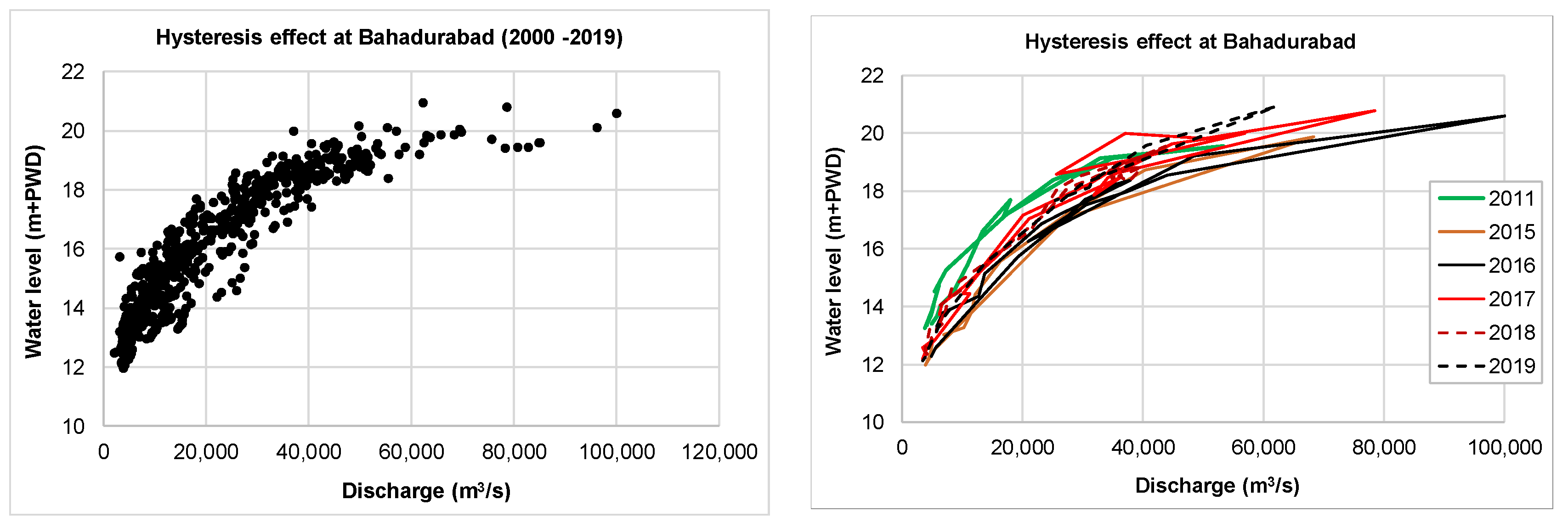
For the Lower Jamuna, the discharge is regularly measured in the Upper Jamuna at Bahadurabad. The observed data during the last 19 years (2000–2019), depicted in the left plot of Figure 3, show a large variation in stage–discharge relationships (up to 4 m difference in water levels for the same discharge). This variation is mostly seen during average to bankfull flow levels (i.e., 20,000–40,000 m3/s), during which the morphological activities are predominant at the Lower Jamuna. Such variation, seen in longer-term observations (19 years), can be attributed to both bed and bank or char erosion at the measurement location. Inaccuracies in measured data must also be considered when reviewing the data. Similarly, we tried to quantify the seasonal changes that may reflect the hysteresis effect due to bed forms as well. The right plot of Figure 3 shows the stage–discharge relationship for some selected recent years. As we can see, the hysteresis effect is apparent (showing magnitude of water level difference of about 1.0–1.2 m), although it is not always noticeable. The right plot of Figure 3 shows that the stage–discharge relationship differs for different years, e.g., the water level is much higher during medium and lower flows (below bankfull discharge) in 2011 compared to the water levels during other years (particularly in 2015 and 2016). The water level at Bahadurabad is higher in 2019 under the same discharge compared to other years. The flood discharges are much higher in 2016 and 2017; however, the water levels are lower than in 2019. This can be attributed either to a larger form drag during 2019 (since the discharge was not high enough for a flat bed transition) or changes in flow conveyance due to changes in banks, chars or sandbars. Contributions from possible measurement errors (including an imprecise discharge–water level relationship in calculations of flood discharges) require further exploration. This analysis shows that the changes in hydraulic characteristics are closely associated with the micro-, meso- and large-scale morphological changes that occur every season depending on the upstream flow variability.
(b) Water levels at Aricha
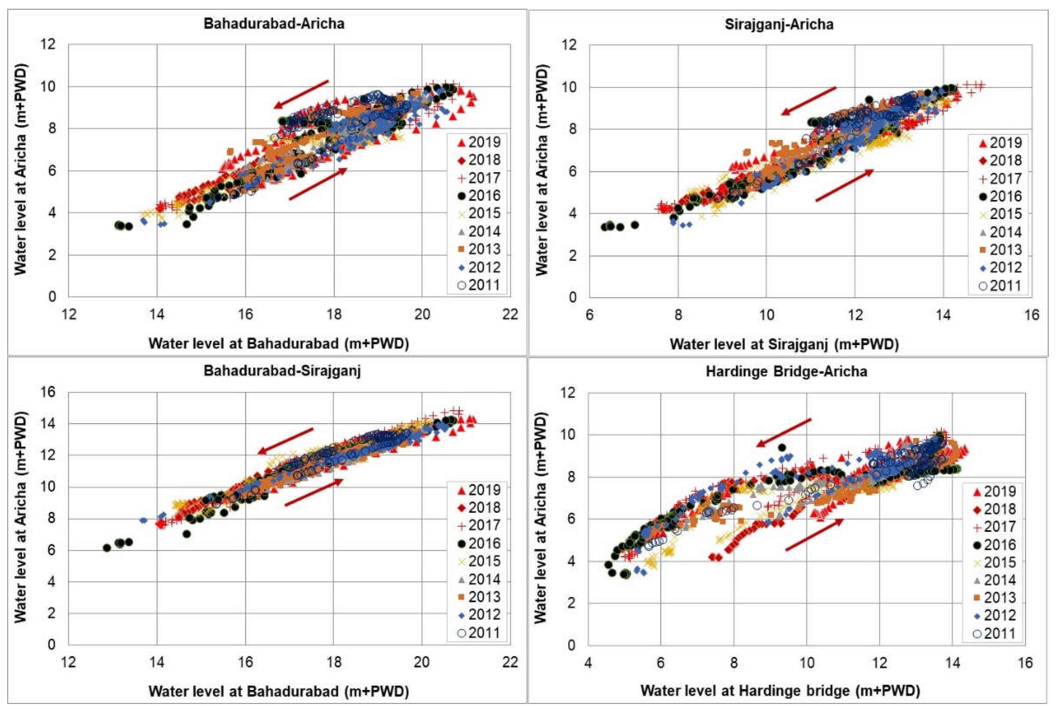
Since Aricha is the downstream boundary of the current study reach (also used in numerical models), it is important to analyze water level variation, particularly the interaction with the Ganges as it is located near the confluence of the Ganges (Padma) and the Lower Jamuna. To understand how the flow of the Ganges-Padma interacts with the Lower Jamuna, we tried to analyze the water level changes at Aricha (located on the Lower Jamuna near the confluence) in relation to the water levels at Bahadurabad (~160 km upstream of Aricha), Sirajganj (~70 km upstream of Aricha) and the Hardinge Bridge (~90 km from Aricha on the Ganges), as shown in Figure 1. The results are depicted in Figure 4.
The water level at Aricha differs noticeably from other stations during the rising and falling stages. For example, for the same water level at Bahadurabad, the water levels at Aricha differ almost 3 m during medium (bankfull) flows. The difference is less pronounced when comparing Sirajganj to Aricha, as Sirajganj is located closer to Aricha. The main explanation for this difference is that water levels at Aricha depend on the combined discharges of the Ganges and the Jamuna, whereas water levels at Bahadurabad depend on the discharges of the Jamuna only. Additional explanations include temporal and spatial lags as well as hysteresis effects in bedform evolution. Lag effects are also evident between the water levels at Bahadurabad and Sirajganj, but these are less pronounced (about 1.5 m max as shown in the lower-left plot of Figure 4). The scatter in the water level relationship between Aricha and the Hardinge Bridge (shown in the lower-right plot of Figure 4) suggests less interaction correlation between these two locations (except during lower flows). The water level at the Hardinge Bridge is almost similar to the water level at Aricha during lower flows of a rising flood; thus, there appears to be some effect of the Lower Jamuna on the Ganges. The Ganges starts to flow relatively freely with the rising discharge as the water level at the Hardinge Bridge becomes noticeably higher than at Aricha.
Considering such complexity related to hydraulic interaction and effects, we used observed data as boundary conditions for the model verification.

2.2.2. Discharge Distributions at the Bifurcations

(a) Observed discharge distribution
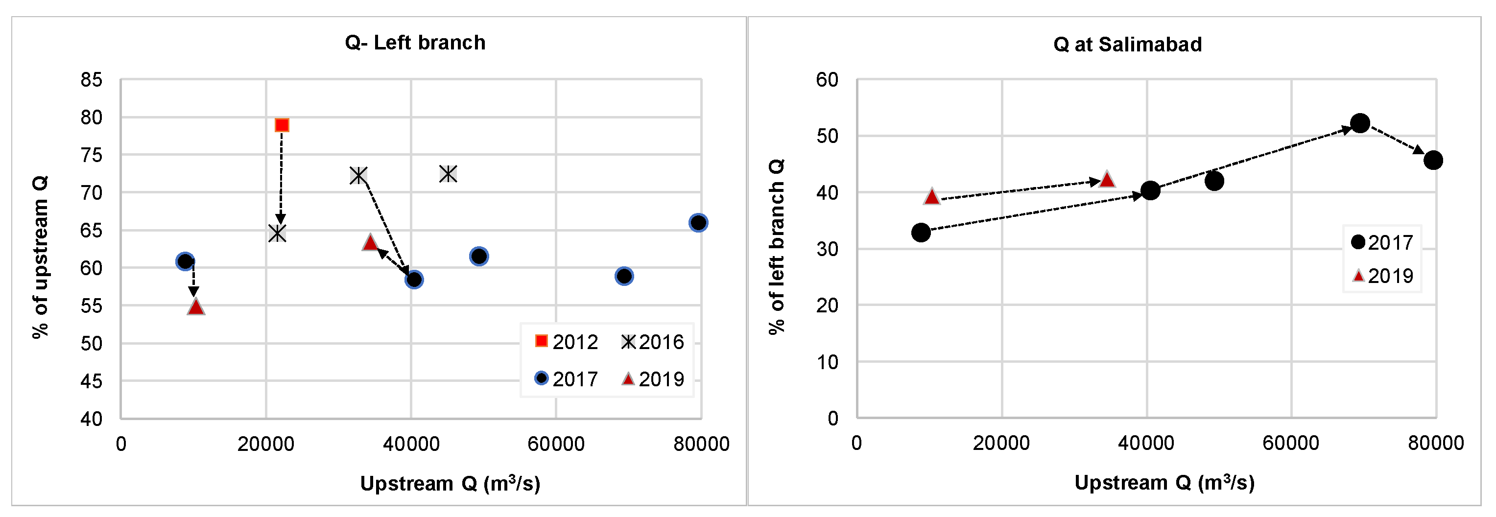
We assessed how the discharge distribution at the bifurcations varied over time (Figure 5). The results show that in 2017 the discharge entering the left branch of the major bifurcation (left plot) remained relatively consistent over most of the upstream discharge conditions (at around 60%). The data show a 6% increase in discharge in the left branch during a high flow condition. This can be attributed to the fact that the branch is wider and less affected by bars and deep channels during high floods. The left plot also shows higher discharges through the left branch in 2012 (~79%) for discharge conditions lower than bankfull. This can be attributed to the presence of a single deep channel towards the left branch and a milder branch angle in 2012 (despite the branch width being narrower). The result shows that in 2016 the discharge towards the left branch was significantly lower (65%) than in 2012 under similar upstream conditions. This can be attributed to the formation of two deep channels in 2016 conveying more flow towards the right branch. The results show that the left-branch discharge increased with increased upstream flow, particularly near bankfull conditions. This can be attributed to the lessened effect of the deep channel during bankfull flow conditions. Furthermore, the branch expanded at Chauhali due to bank erosion during 2015–2016.
In 2019, the conveyance through the left branch shows a lower portion (~55%) under a low flow condition and a higher portion under a bankfull condition (~63%) compared to 2017 measurements. Again, this can be attributed to the effect of the deep channels, i.e., their expansion and migration towards the right branch conveying more discharge towards the branch, particularly during lower flows. In 2019, the deep channels near the Chauhali bend began accreting. On the other hand, during higher flows, the left branch conveyed more discharge, apparently due to the minimized effect of deep channels as well as the milder flow angle towards the left branch during higher discharges. Furthermore, the right plot of Figure 5 shows the proportion of the left-branch flow that is conveyed through the Salimabad channel. The result shows that the Salimabad channel takes more flow at higher discharges. However, at around 80,000 m3/s, the relative Salimabad channel conveyance reduces. This correlates to the case of increased flow through the left branch. The observations in 2019 show slightly higher discharge towards the Salimabad channel when compared to those from 2017 under lower flow and near-bankfull conditions. This can be attributed to the growth of the deep channels despite formation of sandbars. This is elaborated upon in the morphological analysis section below.
(b) Hydraulic modeling of discharge distribution
(i) Model verification
A comprehensive comparison between the model results and measured data at various cross sections is depicted in Figure 2. The results show satisfactory performance of the model despite the complexity of the flow. Specifically, the model satisfactorily replicates discharge distributions at the major bifurcation and the Salimabad channel. An incomplete discharge balance causes a discrepancy in the left-branch flow conditions because potential overland flow on the char had not been measured. This potential overland flow was not captured in the model because of the lack of proper char elevation data. Additionally, some discrepancies can be attributed to poor resolution of the bed topography of small anabranches and a time lag during the measurement campaign.
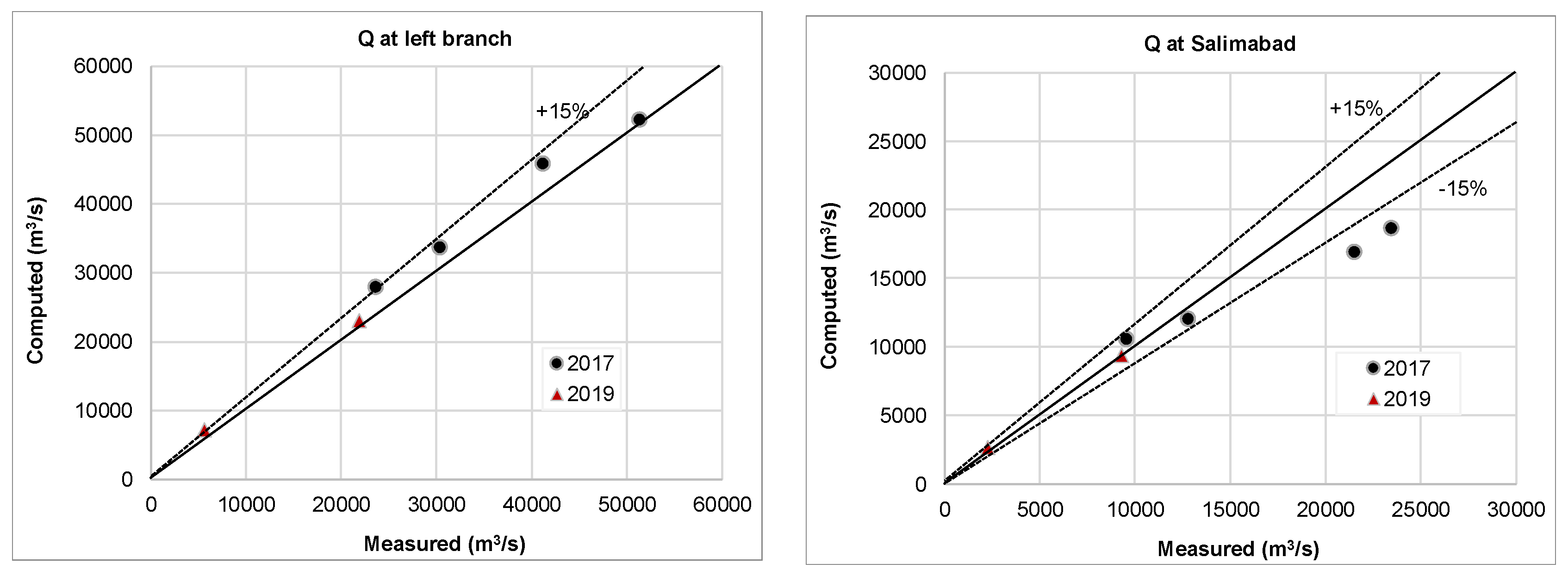
Similarly, we compared the computed and observed discharges for both bifurcations in 2017 and 2019 (Figure 6). While the model reasonably predicted flow division at the major bifurcation, the Salimabad division had some larger discrepancies, particularly at higher flows. The discrepancies can be attributed primarily to a lack of high-resolution data within the channel. Overall, the model performance was found to be satisfactory.
(ii) Model results and discussion
Various scenario simulations were carried out using the models with measured bathymetry of 5 years. The discharge distribution during various steady flow conditions (Table 1) at the bifurcation (showing the discharge at the left branch) and the Salimabad channel is depicted in Figure 7. The Salimabad results do not include 2011 data because in that year the channel was not well developed yet. The results for the bifurcation (Figure 7, left) show that the discharge distribution noticeably alters for low flow (i.e., 3737 m3/s). A large portion of discharge (>90%) was found to be flowing towards the left branch in 2011, 2017 and 2018 under low flow conditions. However, it significantly dropped in 2016 and 2019. This can be attributed to the deep-channel formation and migration towards the downstream branches, e.g., a single deep channel towards the left branch in 2011 caused larger flow towards this branch. In 2016, the deep channels started to split into two, forming a deposition front at the bifurcation, leading to less discharge into the left branch. The deep channels became more prominent in 2017 and 2018, migrating towards the left branch and leading to more discharge in this left branch (this also caused bank erosion at the left side of the upstream channel). Deposition occurred in 2019 along with the development of a prominent deep channel towards the right branch (followed by larger erosion along the right bank of the upstream channel). This deep channel appeared to convey larger flows towards the right branch, although the resolution of the bathymetry data in 2016 and 2017 was rather low, which may cause some inaccuracies in the model prediction.
The results of scenario simulations for the Salimabad channel (Figure 7 right) show that the discharge towards this channel is in the range of 30 to 50% of the left-branch discharge for most of the discharge levels and years except for the lowest flow level. Under the lowest flow condition, the result shows a large portion of discharge (about 70% of the left-branch discharge) towards the Salimabad channel in 2016 and the lowest portion in 2018 (about 20%). The results show that the discharge entering into the Salimabad channel is lower during high floods than during bankfull and annual average flow conditions. The amount of flow entering into the Salimabad channel is still quite large, which implies the effectiveness of the planned channel closure must be investigated in more detail (with close observation during the preceding flood). The situation appeared to be favorable in 2018, but discharge into the Salimabad channel showed an increase again in 2019.

3. Morphological Analysis

3.1. Methodology

3.1.1. Ground Measurement

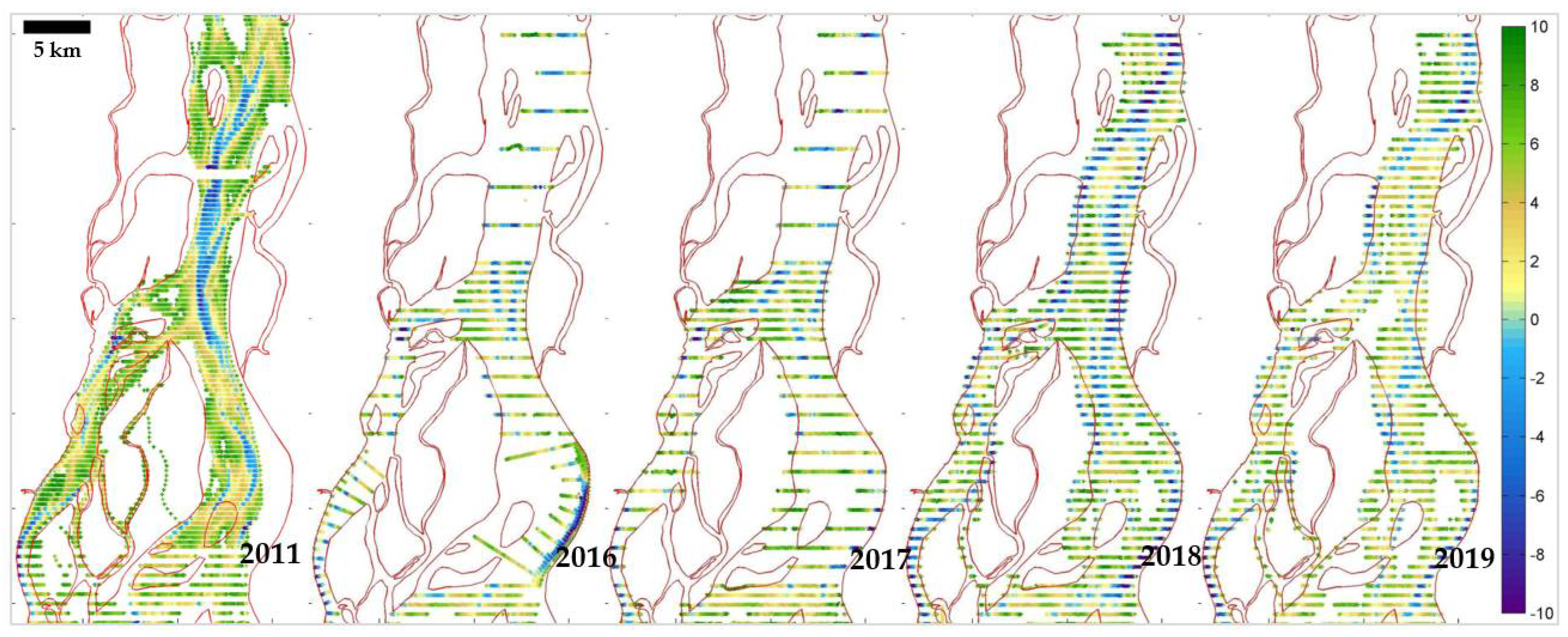
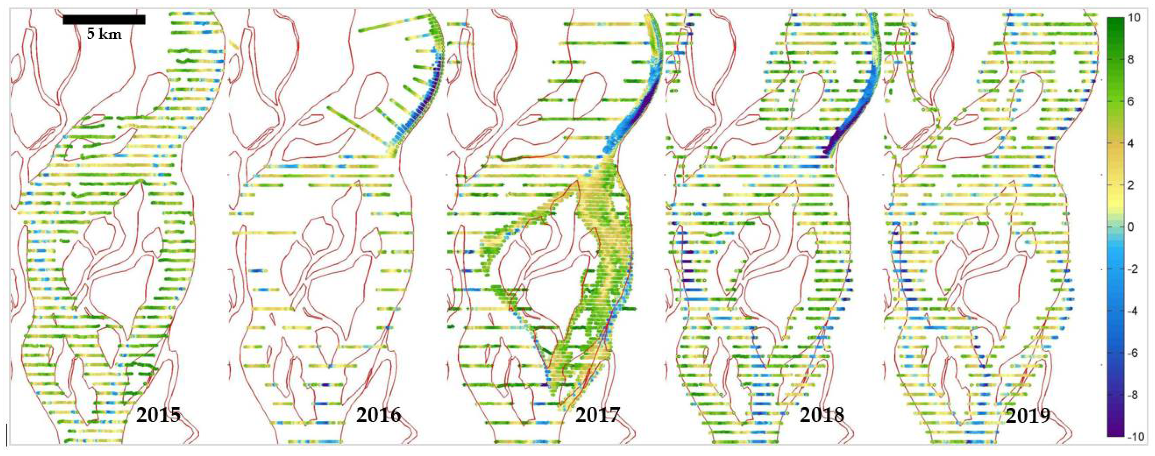
Full bathymetric surveys of the Lower Jamuna were carried out in 2011, 2016, 2017, 2018 and 2019 (Figure 8 and Figure 9). All bathymetric surveys were conducted during the monsoon season (August/September) using a single-beam echo sounder. Resolution of the data varied from year to year. Spacing ranged from 200 m to values in the order of 1 km. The large spacing is a consequence of the large study area and limited surveying resources.

3.1.2. Morphology Monitor (MoMo) Application

We developed an image processing algorithm using the Google Earth Engine [30] to quantify morphological changes within any selected period. All available multispectral satellite images from Landsat 7, Landsat 8 and Sentinel-2 missions for the selected periods can be processed. The analysis process was automated and developed into an interactive tool referred to as MoMo, which is an evolution of the methods developed in Aqua Monitor [31]. The new algorithm computes annual water occurrence by estimating the expected value of the normalized difference spectral water index [32]. It is computed using the equation:
NDWI = ∑w × INDWI
where ῙNDWI is the resulting average value of the normalized spectral water index; INDWI is a normalized water index image computed from top-of-the-atmosphere (TOA) reflectance values; and w is a weighting factor indicating the quality of reflectance values at every pixel and is computed as an inverse brightness of TOA reflectance values—brighter pixels which represent clouds receive lower weight values [33]. This ensures that cloud artifacts are removed in the final average image. The water occurrence is then estimated by normalizing the final average index value using 0.05 and 0.15 thresholds applied for INDWI on a per-image basis. Advantages of this method are: (i) high-quality estimate of annual water occurrence, (ii) automated-processing-like extraction of geometry and topology, (iii) a robust and accurate method of water body detection and delineation, (iv) estimation of temporal changes in water surface area and (v) monitoring and estimation of accretion and erosion (spatial and temporal variation, but not the volume). The final estimate of the surface area of water and sandbars was computed by thresholding the resulting water occurrence. The thresholds were found empirically. The quality of the resulting water occurrence depends on the frequency of the satellite images available for every year. The observation frequency of the Landsat 7, Landsat 8 and Sentinel-2 images varies significantly between 1990 and 2020 (the period considered in this study). The image acquisition has become much higher after 2015 due to the launch of the Sentinel-2A satellite, and has increased even more after 2017 with the launch of Sentinel-2B. The developed algorithm filters a large number of collected images (between two monsoon seasons) from clouds and noise and processes them to derive the image annually based on frequency analysis of water occurrence.
We made a comparison between the MoMo and Pekel’s water occurrence maps. The main difference is that Pekel computes binary water masks aggregated to the monthly time intervals, while the MoMo algorithm computes statistics of spectral water indexes without binarization. Therefore, the output is a continuous variable representing the probability of water/land presence. Our method can capture more local details (higher precision). A small example with a visual comparison of Pekel’s and our results for a small part of the Jamuna River is shown in Figure 10.
The MoMo application can be used to quantify the erosion and deposition areas for any selected period and reach. The developed application allows the specification of any area(s) by using polygons, within which the area and its changes are computed for any selected threshold values for water occurrence frequency as well as the period. The lowest level is the minimum water level, which corresponds to 100% of water occurrence frequency (i.e., the area that remains 100% under the water throughout the year). The highest level is the land that corresponds to 0% of water occurrence frequency (i.e., the area that is always dry). These upper and lower thresholds of water occurrence frequency were set at 97% and 3%, respectively, to avoid the noise (this can be chosen based on user’s assessment) and normalized again to be 100% and 0%. In this study, several higher levels were considered by selecting different water occurrence frequencies, namely 0%, 25%, 50% and 75%. Thus, the changes in eroded or accreted areas were computed within the range between the minimum water level and four different higher levels above it, depending on selected water occurrence frequency (e.g., 0% means the level that is always dry (chars, banks), whereas 25% means the areas that are under water 25% time of the year and so on). This provides a quantitative idea about the changes (erosion and accretion) in different dynamic ranges between the floodplain and the minimum water level. This means that the image analysis is not merely a static comparison of two images but a statistical analysis of a large number of images in order to obtain information on the dynamics of the system. This is useful and relevant for large rivers such as the Lower Jamuna with a large annual variation between lowest and highest water levels. MoMo thus allows for the detection and quantification of a large part of the morphological features. There could be some inaccuracy in the result of the annual changes in morphological features if a very dry year is followed by a very wet year. Secondly, the method only allows for the computation of the changes in areas and not in volumes.

3.1.3. Morphological Modeling

We applied morphological models to replicate and predict short-term morphological behavior, particularly dynamics of deep channels and sandbars. The model, described above (in Section 2.1.2), was extended with the morphological module of Delft3D. A user-defined general sediment transport formula, developed for the Jamuna, was selected, which approximately represents the formula developed under the Flood Action Plan [8]. The formula reads S = α D 50 Δ g D 50 θ b , where S is the total bed material load (bed and suspended load), D50 is the mean sediment diameter, Δ is the relative density, g is the gravitational acceleration, θ is the Shields parameter and α and b are calibrated parameters, 40 and 1.82, respectively. A uniform sediment size of 0.15 mm was applied in the model. Three-dimensional effects, such as secondary flow, were included in the model with a parameterized approach [34]. There are certain limitations and challenges for prediction of such complex processes by using physics-based models. Nevertheless, it is a useful tool with which to capture short-term changes such as deep-channel and sandbar propagation. The model can be regularly improved and applied in complement with other data and tools, shown in this study, to support adaptive river stabilization efforts.

3.2. Results

3.2.1. Reach-Average Bed Level Changes

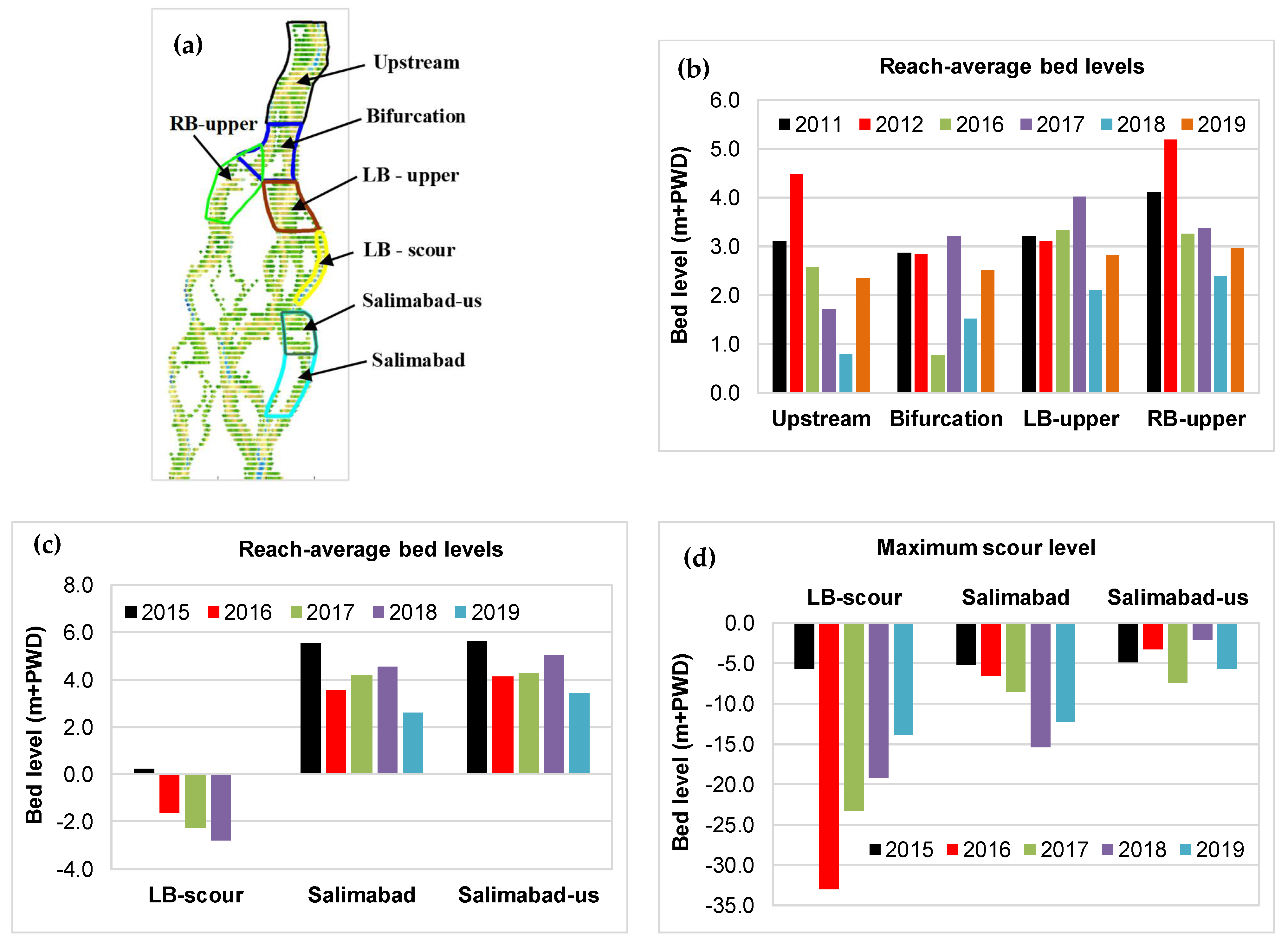
The reach-averaged bed levels (captured by the survey data) are depicted in Figure 11. The upstream reach of the bifurcation shows about 1.5 m deposition in 2012. A capital dredging project near the Jamuna Bridge in 2012 led to the erosion of a mid-channel char. The eroded material could have been transported downstream and deposited along the reach upstream of the bifurcation (see upper-right plot of Figure 11). However, the bed level shows erosion after 2012 until 2018 in this reach. The erosion can be attributed to the formation of deep channels, bank erosion and shifting (and maybe eroding) of sandbars. Again, the deposition observed in 2019 can be attributed to the formation of sandbars and filling of deep channels in this reach. Within the bifurcation reach, there is almost no change in bed levels during 2011–2012. However, there was a significant decrease in 2016, which can be attributed to the formation of deep channels at the bifurcation. In subsequent years, bed levels increased and decreased alternatingly each year. This can be due to the deposition in front of the central char (at the bifurcation point), which grew upstream, forming a long central bar. This may lead to the shifting of the bifurcation point upstream.
The upper reach of the left branch (LB-upper) shows slight erosion in 2012 whereas the bed level increased in 2016 and 2017. This can be attributed to deposition of eroded materials transported from upstream. Large erosion in this reach in 2018 can be attributed to formation of a cut-off channel and bank erosion of the central char. There was again deposition in 2019 (compared to 2018), due to the filling up of deep channels. The deep channel along the Chauhali bend in the left branch (LB-scour) deepened until 2018. More recently the bed level seemed to be returning to the level of 2015 (showing 0 level in 2019). This implies that the deep channel (scour) along the bend is filling up. The bank along the Chauhali bend eroded in 2015. Additionally, since reaching its maximum scour in 2016, the deep channel along the Chauhali bend has been decreasing (over three years the maximum scour depth has decreased to about 20 m). On the other hand, the upper reach of the right branch (RB-upper) shows noticeable bed level increase in 2012. However, it shows significantly decreased bed level in subsequent years till 2018. In 2019, the bed levels in this reach increased again. This can be attributed to the formation of deep channels till 2018, which appeared to be slightly shallower in 2019.
We also assessed the average bed levels in the upper and lower part of the Salimabad channel. The results are shown in the lower plots of Figure 11. The channel has been eroding since 2015, although it shows some sedimentation in 2017 and 2018. However, the channel eroded again in 2019. Compared to 2018, the maximum scour level in the upstream part and the bed level decreased in the downstream part. Since there was no measurement at the shallow areas (e.g., sandbar deposition at this channel) in 2019, the reach-averaged erosion could be overestimated. As measurement resolution was not always the same, the quantitative comparison of reach-averaged values should be considered with care and in combination with image analysis. The changes in sandbars and chars were better captured in the image analysis, presented in Section 3.2.3.

3.2.2. Deep-Channel Evolution

We attempted to detect the deep-channel evolution based on raw bathymetry measurement data without any interpolation (since the resolution of the data is not the same in all measured years). The bathymetry measurements of 2011 and 2016 to 2019 for the upstream channel and branches are depicted in Figure 8 and Figure 9. One major deep channel upstream of the bifurcation in 2011 propagated towards the left branch and had a meandering pattern. In 2016, two deep channels were formed at the bifurcation, one of which diverted towards the right branch in 2017. This can be attributed to the formation of a mid-channel bar and its propagation towards the bifurcation, which could be caused by the changes in upstream conditions, such as erosion at the Jamuna Bridge triggered by the capital dredging. These two deep channels became more apparent in 2018, causing further bank erosion along both sides of the upstream channel. As the data of 2019 show, some parts of the deep channels filled up, particularly along the left bank, whereas another deep channel began to meander, hitting and eroding the right bank at Enayetpur. These developments make the char and thus the bifurcation vulnerable. Figure 8 also shows substantial deposition in front of the bifurcation point at the central char. This is unfavorable for bifurcation stability.
Figure 9 shows the dynamics of deep channels at the Chauhali bend and Salimabad channel. The deep channel was already present in this bend in 2011, which eventually led to bank erosion along the Chauhali bend in later years. The bank was protected in 2016, and therefore bend scour along the protected bank is visible in the bathymetry data. The scour propagated mostly in downstream direction. The bathymetry data of 2019 show the filling of the deep channel along the bend. The deep channel towards the Salimabad channel eroded the adjacent char. Despite sedimentation along the inner (left) part as well as along the char in the downstream end, the deep channel turns sharply (as a meandering channel), causing significant bank erosion in the downstream part of the Salimabad channel. Since there was a plan to close this channel to reclaim the land, the sedimentation in the channel could help to close it naturally with some soft intervention. However, the evolution of deep channels as well as a rapidly changing upstream morphological condition in the Chauhali bend (i.e., sedimentation along the bend and formation of a cut-off channel) could be unfavorable for closure of the channel.

3.2.3. MoMo Analysis

(a) Detecting spatial and temporal changes
Morphological changes during different periods, such as erosion and sedimentation, lateral movement and bank erosion as well as migration of sandbars, were evaluated using MoMo. In this paper, we demonstrate the first results on how MoMo can be used to quantify and analyze changes in morphology for any selected period during 1990–2020. The image year implies the processed images during the monsoon of that year to the monsoon of the subsequent year (e.g., the image 2019 includes the image from the monsoon of 2019 to 2020).
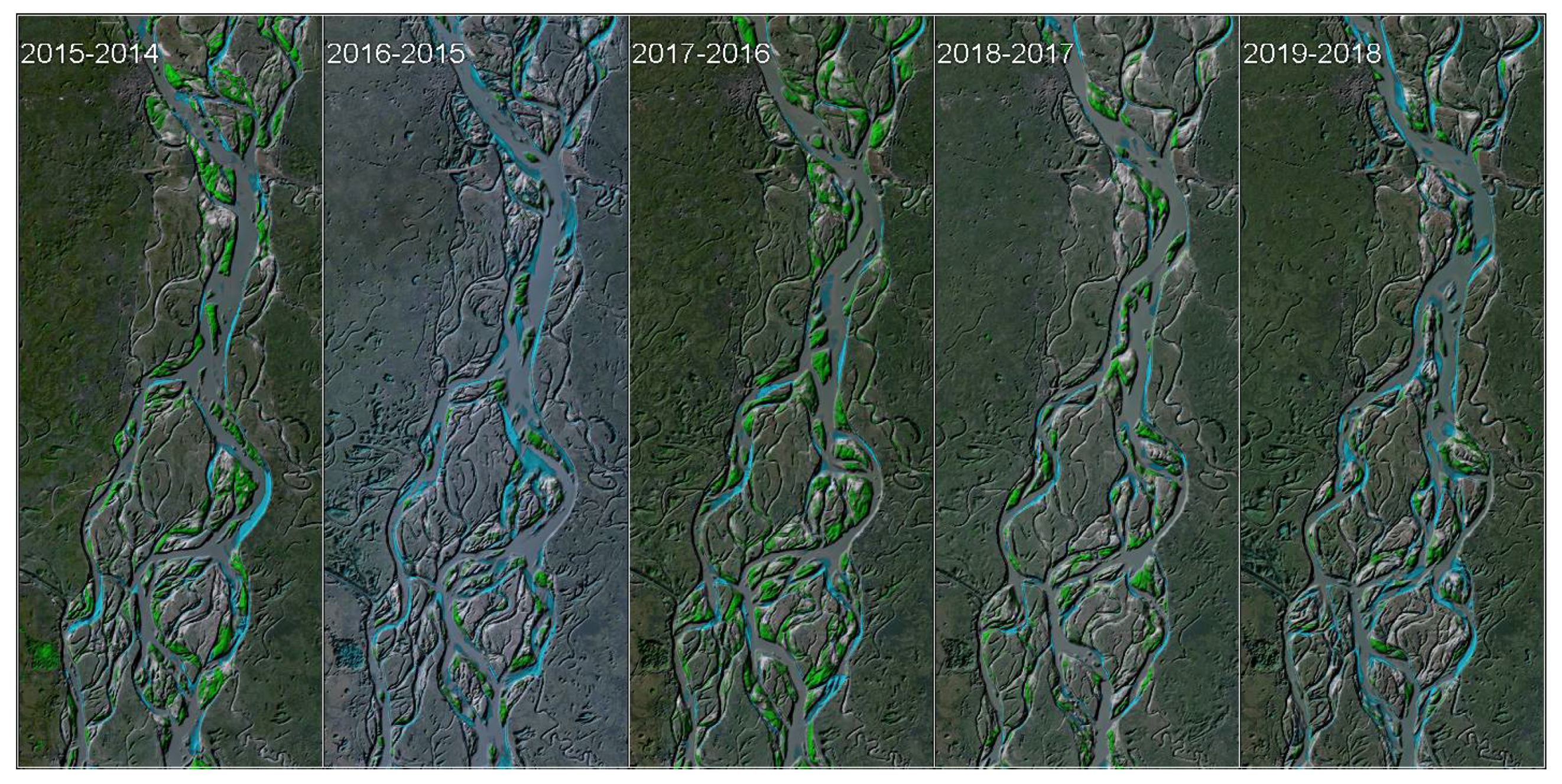
Firstly, we quantified decadal changes since 1990. The changes during 1990–2000, quantified by MoMo for the period of 1990–2000, shows large erosion and that the major bifurcation was not formed yet (leftmost plot of Figure 12). The upstream channel stabilized during 2000–2010 (the period after the construction of the Jamuna Bridge), leading to formation of chars at both banks as well as a major bifurcation. However, large changes occurred in the Chauhali bend and the Salimabad channel during 2010–2015, depicted in the third plot of Figure 12 (large bank erosion at Chauhali in 2015). The changes during the last 4–5 years show mostly erosion (as can be seen in the rightmost plot of Figure 12). The upstream channel has become unstable with continuous bank erosion due to the formation of mid-channel sandbars as well as changes in the deep-channel pattern during this period (this is better visible in bed topography data, Figure 8). The Chauhali bend shows accretion along with the formation of a cut-off channel. This might cause abandoning of the deep channel along the Chauhali bend (which formed after the protection measures). The right branch shows erosion during the last 4–5 years, which can be attributed to the formation of two deep channels at the upstream reach apparently causing larger flow towards the right branch during low and medium flows (this is clearly visible in the bed topography data too). Such a morphological development is a threat to the bifurcation stability. Additionally, the Salimabad channel shows changes in deep-channel patterns leading to char and bank erosion. At the same time, sandbars form along the char at the downstream reach of this channel causing further threats to the opposite (outer) bank. Furthermore, we quantified annual morphological changes during 2014–2019, depicted in Figure 13. The result captures well the bank erosion at the Chauhali bend during 2014–2015. The erosion of banks and chars is visible during most of the years. Some sedimentation occurred in 2017–2018, although the changes during 2018–2019 show erosion of chars and banks at most of the anabranches, particularly at the Salimabad channel.
(b) Quantifying eroded and accreted areas
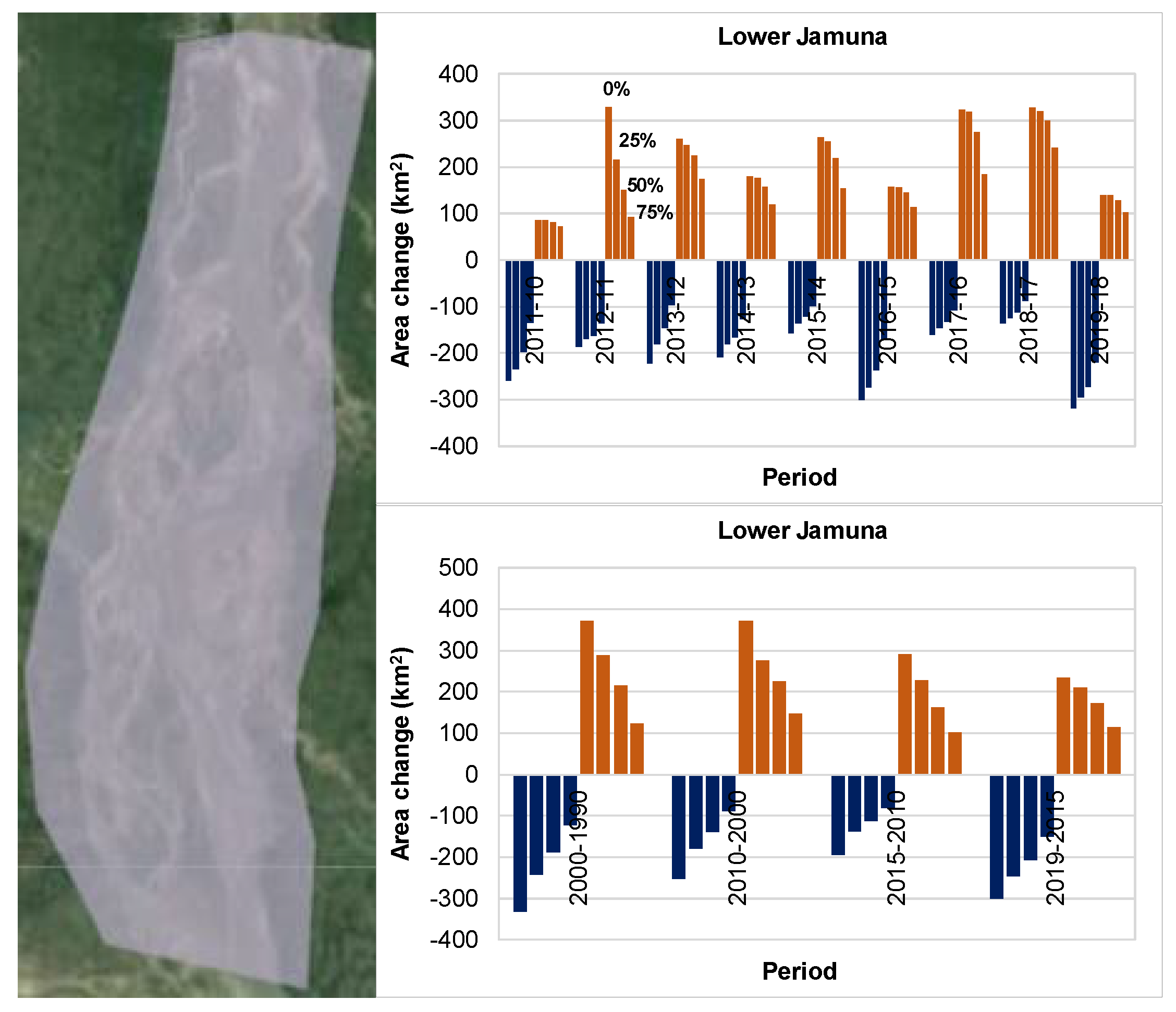
First, we attempted to quantify the changes within the selected reach of the Lower Jamuna (as shown in the left plot of Figure 14), computing the eroded and accreted areas annually as well as with 5-year and decadal intervals. We considered the threshold range between 100% (representing minimum water level) and 0%, 25%, 50% and 75% water occurrence frequency (representing different upper levels). We computed the changes (accreted and eroded areas) for a reach of the Lower Jamuna from the Jamuna Bridge to the confluence with the Ganges (shown by a polygon in the left image of Figure 14). The result is depicted in Figure 14 (right plots), in which the eroded and accreted areas in annual (upper right) as well as decadal and 5-year intervals (lower right) during 2000 to 2019 were quantified for all selected ranges of water occurrence frequency. The result of annual changes (upper right) shows that erosion was dominant in specific years (e.g., 2015–2016 and 2018–2019) and deposition in other years (e.g., 2010–2011, 2016–2017 and 2017–2018). The variation in areas for selected upper-level water occurrence shows the decrease in areas of both erosion and sedimentation with the increase in water level occurrence that considers different upper levels above the minimum water level. This is obvious, since the considered areas reduce with increasing water occurrence (i.e., the upper layers). However, the pattern of variation in area changes is different in different years. For example, the changes in accreted areas during 2010–2011 for varying water occurrence is minimal. Accreted areas vary more drastically during 2011–2012 for varying water occurrence. This has to do with the dynamics of banks, chars and high-amplitude sandbars within the range of minimum water level and the floodplain. This does not reflect the morphological changes below minimum water level that are not captured by the images.
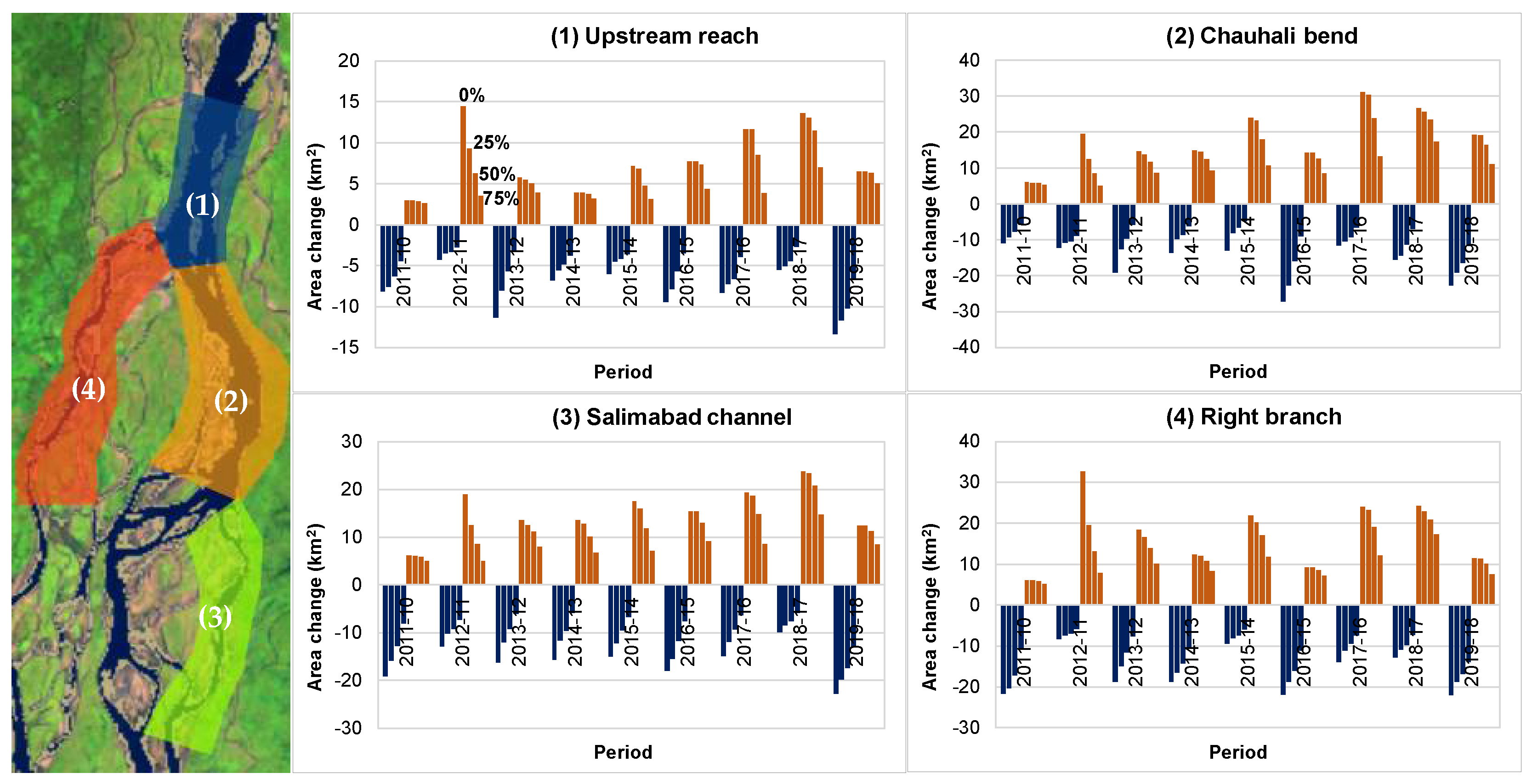
Furthermore, we selected a few critical areas along the Lower Jamuna as depicted in Figure 15 (left plot) to quantify the changes in accreted and eroded areas for different upper layers (by varying water occurrence frequency). Annual variation in eroded and accreted areas in different selected reaches is shown in the right plot of Figure 15 for the maximum range of water occurrence frequency (0 to 100%). The result for the changes in the upstream reach (upper-left of Figure 14) shows large sedimentation during 2011–2012, which could be an effect of the supplied material generated due to the impact of dredging near the Jamuna Bridge. This trend was also evident in deeper parts of the reach as shown above in the bathymetry data analysis. The changes during recent years (e.g., 2018–2019) show larger erosion compared to previous years. However, the deeper part showed greater sedimentation compared to previous years (as shown above in the bathymetry data analysis). This implies that the banks and chars were eroded, but the deep channels accreted during 2018–2019. The Chauhali bend (upper right of Figure 15) shows larger changes (erosion) during 2015–2016, which corresponds to large bank erosion that occurred during this period. There was mostly accretion in this reach till 2018, but in recent years there was more erosion, although the bathymetry analysis showed accretion of deeper channels and bend scour in this reach. The result for the Salimabad channel (lower left of Figure 15) shows more erosion than accretion during 2018–2019. This can be attributed to the erosion of the char and banks. The bathymetry data analysis also showed a similar erosion trend in 2019 compared to the previous year. The result for the selected upper reach of the right branch (lower right of Figure 15) shows more erosion than accretion in 2018–2019. There was large accretion in this reach during 2011–2012, and a similar trend was found in the bathymetry analysis as well. Similarly, there was more accretion than erosion during 2014–2015, 2016–2017 and 2017–2018, whereas more erosion occurred in 2015–2016. As can be seen from the variation in the accreted and eroded areas under varying upper levels of water occurrence (indicated by 0% to 75% in Figure 15), the areas change differently in different years. For example, the variation in accreted area for varying water occurrence was more drastic during 2011–2012 in all reaches. This implies there was a larger change in the upper part (i.e., formation of high-amplitude sandbars) but less in the deeper part. For some other years the variation in accreted areas was more uniform for varying ranges of the upper and lowest water levels.
The changes in sandbars, chars and banks within the range of low and high water levels can be well captured and quantified by applying the advanced statistical image processing algorithm to a large number of satellite images. However, there are some limitations and uncertainty. For example, the morphological changes above minimum water level (captured by the images) do not necessarily correspond to the changes in deeper parts (found in bathymetry measurements). This stands to reason as, for instance, material eroded from the upper part of the river can be deposited in the deep channels. There is also uncertainty with quantifying differences in accreted and eroded areas, particularly when two compared years have very different high and low flows. MoMo can be improved further in combination with water level observations to deal with these uncertainties. The possibility of rigorous processing of satellite images from various sources appears to enable quantification of volumes and reconstruction of the bed topography in combination with other sources of remote sensing (e.g., LiDAR, ICESat-2 data) and ground observation data. This is the subject of our future work.

3.2.4. Morphological Modeling

(a) Model verification
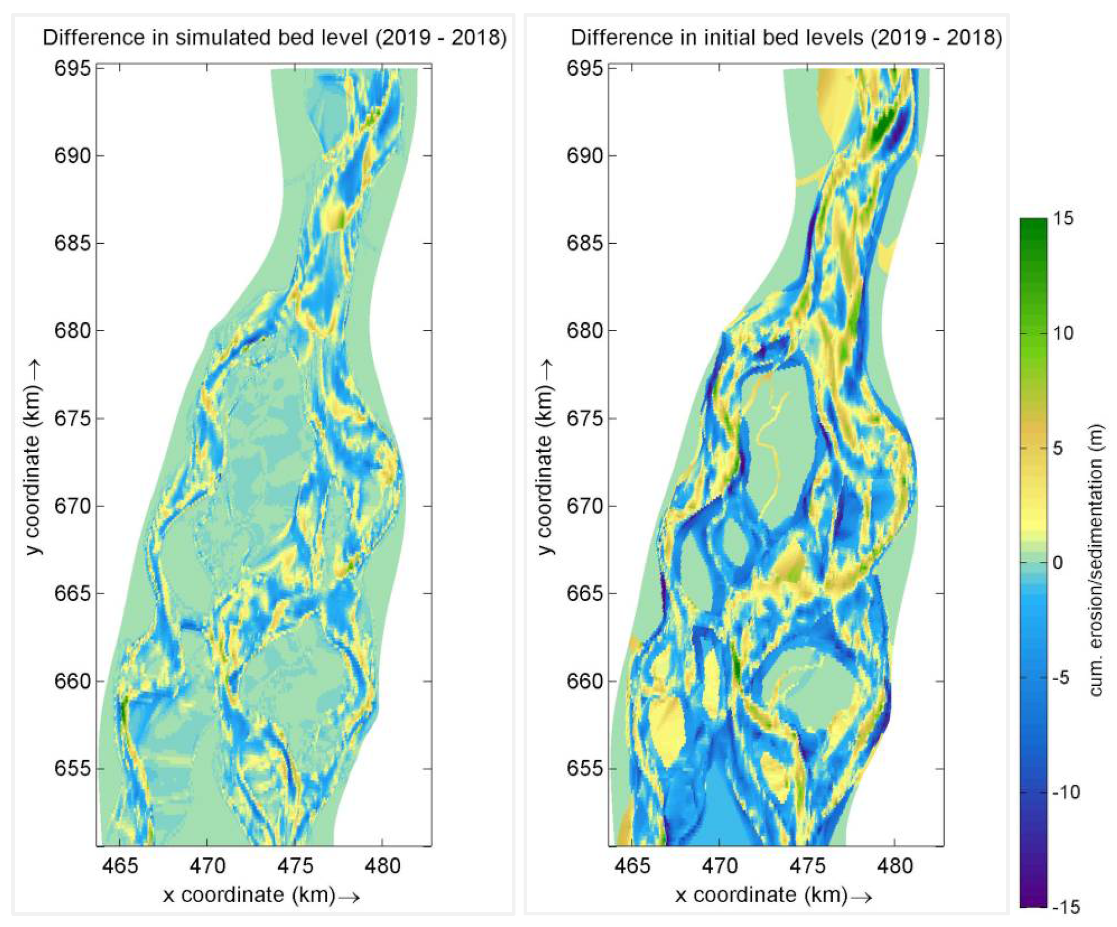
The morphological model was verified and applied in several scenarios. In this paper, we only present the performance of the 2018 model under observed 2018–2019 flow conditions. The verification addressed to what extent the model replicated the observed morphological changes between 2018 and 2019. The simulated and observed bed level differences are depicted in Figure 16. The observed bed level differences show rather large changes whereas the model simulation shows less erosion and sedimentation. Nevertheless, the observed and simulated erosion and deposition patterns are similar in many locations despite the differences in magnitude, e.g., sedimentation at the bifurcation point, deep channel formation along the left bank from the upstream channel to the left branch, filling up of the bend scour at the left branch as well as deposition at the Salimabad channel. The model needs to be improved in future.
(b) Morphological prediction
The model was used to simulate two years of morphological development scenarios. The results are depicted in Figure 17, which shows erosion and sedimentation at the upstream channel, erosion near both banks at the bifurcation, deep channels towards the right branch and sedimentation in the Chauhali bend and the Salimabad channel (but erosion near the banks in the downstream reach).
The Lower Jamuna is a morphologically complex reach. Moreover, the performance of the model is sensitive to model inputs such as the resolution of bed topography. Therefore, morphological model results inevitably exhibit uncertainties. Nevertheless, a numerical model is a good predictive tool if the results are interpreted with careful expert judgement. At this stage, the numerical model can be used to assess only short-term trends (up to two years ahead) and impacts. The model does not include proper bank erosion submodels, which could be important for simulating extreme scenarios and impacts.

4. Discussion: Implications for Adaptive River Management

Our observations, analyses and model predictions revealed the following key problems and risks to be considered for adaptation of the present stabilization plan and measures for the Lower Jamuna:
  • The upstream reach of the bifurcation (downstream of the Jamuna Bridge) has become vulnerable due to deep-channel formation and migration, leading to bank erosion. The right char (near Enayetpur) may undergo further erosion that would eventually lead to the collapse of the major bifurcation.
  • There is a deep-channel (cut-off-like) formation in the left branch followed by deposition along the Chauhali bend. This implies that the left branch is narrowing and abandoning the bend (appears to be returning to the pre-2015 planform).
  • The deep channel has become more prominent at Salimabad (eroding the char and banks there) despite some sedimentation in the form of sandbars, leading to difficulties in realizing the channel closure measure. This requires some trial soft and no-regret measures (e.g., a sand plug) following the natural development of this channel. The changes in upstream morphological conditions (i.e., formation of a cut-off at the Chauhali bend) may lead to partial abandonment of this channel. This shall be observed in coming years. The model prediction shows sedimentation in the Salimabad channel (particularly in deep channels), but erosion near the bank in the downstream reach.
  • Larger flow towards the right branch in 2019, due to the formation and migration of a deep channel upstream of the bifurcation, has resulted in large changes in banks and anabranches at some locations along this branch. This has also altered the flow exchanges between the anabranches downstream. These changes should be considered while adapting the river management plan.
  • The morphological model also predicted large morphological activities with erosion near the banks at the upstream channel, deep channels and sedimentation. These changes would mean that the bifurcation is vulnerable.
  • There should not be any delay in adapting the river stabilization measures, since a single season may lead to large changes, particularly as the upstream condition is rather uncertain with flood peaks that can vary from 40,000 to 100,000 m3/s, leading to morphologically unfavorable conditions.

5. Conclusions and Recommendations

A combination of historical data, regular ground measurements, an automatized satellite image processing application and numerical models has been found to increase the understanding of the hydraulic and morphological behavior of the Lower Jamuna and its bifurcations. It also helps to detect and predict the vulnerability of the banks and chars, which are important for erecting and adapting erosion management measures and plans.
Below are some main conclusions drawn from the analysis:
  • Discharge distributions at the bifurcations and anabranches vary based on hydraulic and morphological conditions. From the analysis of the observation data, it is evident that the deep channels had noticeable effects on discharge distribution, particularly under lower flow conditions. Under bankfull conditions, the bifurcation planform (large-scale) appears to be a dominating factor for discharge distribution. This implies that, under lower flow conditions (including annual average flow), the flow distribution at the bifurcation does not appear to be governed by the large-scale planform (e.g., bifurcation angle and width), but by the deep-channel formation and migration. It is important to consider the lower flow condition given that it occurs during more than three quarters of a year and contributes to large deep-channel activities, leading to, for example, toe erosion along the banks and chars, making them vulnerable to collapse during higher flows.
  • The changes in discharge distribution at the bifurcation within the range of 10–15% did not seem to have a large impact on bifurcation stability. Instability of the upstream channel due to the channel dynamics and bank or char erosion may eventually lead to the instability of the bifurcation and downstream branches.
  • The hydraulic analysis showed a hysteresis effect in the stage–discharge relationship at Bahadurabad. Therefore, a stage–discharge relationship should be derived properly and used with care.
  • The interaction between the Ganges (Padma) and the Lower Jamuna at Aricha shows that the Ganges flow is affected by the Lower Jamuna during lower flows of the rising stage. It flows more freely with the rising discharge when the water level at the Hardinge Bridge surpasses that of Aricha. On the other hand, the effect of the Ganges flow at Aricha was only evident when the Ganges discharge was higher than the Lower Jamuna discharge, particularly when the water level at the Hardinge Bridge was higher than at Sirajganj (which was the case during some years, mostly during the falling stage of the Jamuna flood).
  • The major bifurcation had been dynamically stabilizing since the construction of the Jamuna Bridge in 1998. However, the observations showed noticeable erosion during 2011–2016 with deep-channel formation and migration followed by large bank and char erosion. Recent observations showed that the deep channels were still actively eroding the char and banks in the upstream reach of the Lower Jamuna (e.g., near Enayetpur). Moreover, the right branch has been growing for the last few years (the angle of the deep channel towards the right branch has become milder due to its widening, leading to increased conveyance towards this branch in 2019). The floodplain near the upstream channel has become vulnerable to further erosion, particularly along the right bank, which threatens both the stability of the char and the bifurcation. There is a high risk that the char near Enayetpur, which was formed after the construction of the Jamuna Bridge, could be eroded under unfavorable flow conditions.
  • Deep-channel propagation is prominent at flows lower than bankfull, whereas sandbars propagate largely during floods. The time scale of the deep-channel dynamics is shorter than the time scale of the sandbar dynamics. Moreover, deep channels are morphologically active throughout the year and have a greater overall effect during the flow condition lower than bankfull. Higher floods lead to sandbar transport and the filling up of deep channels.
  • Dredging exercises, particularly those triggering the formation of a new channel that instigates large amounts of erosion and sedimentation, can cause downstream instabilities. Additional sediment can be deposited as sandbars, leading to deep-channel formation and migration, eventually causing channel widening followed by char and bank erosion. Likewise, bank erosion can cause instability to downstream sections of the river because of the added sediment load, leading to the formation of sandbars and deep channels. Therefore, preventing bank erosion is key to stabilizing the bifurcation and branches.
It is recommended to continue regular monitoring as well as to develop generic methodologies and formulations alongside improving the MoMo application and process-based morphological models. It is also suggested to enhance and transform the existing knowledge and methods (tools) into a comprehensive integrated platform. This shall include a well-established Information, Monitoring and Early Warning System (IMEWS), supplemented by knowledge-based tools for risk detection as well as short- and mid-term prediction and forecasting as a decision support system for adaptive river management in a more efficient and automatized way.

Author Contributions

Conceptualization, S.G., A.T., K.O. and E.M.; methodology, S.G., A.T., G.D. and K.O.; software, S.G., A.T. and G.D.; verification, A.T., S.G. and G.D.; formal analysis, S.G., A.T., G.D. and K.O.; investigation, S.G., A.T., K.O. and E.M.; resources, K.O., E.M. and J.A.; data curation, A.T., S.G., K.O. and J.A.; writing—original draft preparation, S.G.; writing—review and editing, A.T., K.O., E.M., G.D.; visualization, S.G., A.T. and G.D.; supervision, K.O., E.M. and J.A.; project administration, K.O., E.M. and J.A.; funding acquisition, K.O. and E.M. All authors have read and agreed to the published version of the manuscript.

Funding

This research was carried out as a part of the FRERMIP.

Data Availability Statement

The data can be received upon the request.

Acknowledgments

We would like to thank the Asian Development Bank and the governments of Bangladesh and the Netherlands for financing parts of this research in the framework of the FRERMIP. We also thank other members of the FRERMIP team for their assistance, particularly Gerrit Klaassen and Maminul Sarker for their thoughtful input. We also would like to thank Saleh Adib Turash and Jesper Mathiesen for assistance in processing data and GIS work. Additionally, we acknowledge the support from the Deltares strategic research program for developing the Morphology Monitor application.

Conflicts of Interest

The authors declare no conflict of interest.

References

  1. Northwest Hydraulic Consultant and Euroconsult Mott MacDonald. River Stabilization and Development. Supplementary Annex A, Vol. 3. Strategic Environmental and Social Assessment (SESA) of River Stabilization. Prepared by Wim Giesen and Wandert Benthem under Flood and Riverbank Erosion Risk Management Investment Program for Bangladesh Water Development Board. 2020.
  2. Asian Development Bank Report and Recommendation of the President to the Board of Directors. Proposed Multitranche Financing Facility People’s Republic of Bangladesh: Flood and Riverbank Erosion Risk Management Investment Program. June 2014.
  3. Northwest Hydraulic Consultant and Euroconsult Mott MacDonald. River Stabilization and Development. Supplementary Annex D, Vol. 1. River stabilization Plan—Technical basis. Prepared by Gerrit Klaassen under Flood and Riverbank Erosion Risk Management Investment Program for Bangladesh Water Development Board. 2020.
  4. Rennell, J. The Ganges and Brahmaputra River. Philos. Trans. R. Soc. Lond. 1781, 71, 91–103. [Google Scholar]
  5. Coleman, J.M. Brahmaputra River: Channel processes and sedimentation. Sediment. Geol. 1969, 3, 129–239. [Google Scholar] [CrossRef]
  6. Latif, A. Investigation of Brahmaputra River. Proceedings of the American Society of Civil Engineers. J. Hydraul. Div. 1969, 95, 1687–1698. [Google Scholar] [CrossRef]
  7. Bristow, C.S. Brahmaputra River: Channel migration and deposition. In Recent Developments in Fluvial Sedimentology; Ethridge, F.G., Flores, R.M., Harvey, M.D., Eds.; The Society of Economic Paleontologists and Mineralogists: Littleton, CO, USA, 1987; pp. 63–74. [Google Scholar]
  8. Delft Hydraulics and DHI. Flood Action Plan (FAP) 24 River Survey Project; Final Report, Main Volume (Prepared for FPCO): Dhaka, Bangladesh, 1996; p. 280.
  9. Water Resources Planning Organization, Ministry of Water Resources. WARPO 1995: Summary Report Based on Studies Carried out under the Flood Action Plan; Water Resources Planning Organization, Ministry of Water Resources: Dhaka, Bangladesh, December 1995.
  10. Thompson, A.; Oberhagemann, K.; She, Y.; Haque, A.M.A. The behavior of self-launching geotextile bag aprons- latest investigations from the Lower Brahmaputra in Bangladesh. In Proceedings of the 9th International Conference on Scour and Erosion, Taipei, Taiwan, 5–8 November 2018. [Google Scholar]
  11. EGIS. Developing and Updating Empirical Method for Predicting the Morphological Changes in the Jamuna River; EGIS Technical Note Series 29; EGIS: Dhaka, Bangladesh, 2002. [Google Scholar]
  12. CEGIS. Long-Term Erosion Process of the Jamuna River; Prepared for Jamuna-Meghna River Erosion Mitigation Project; CEGIS: Dhaka, Bangladesh, 2007. [Google Scholar]
  13. CEGIS. Improve and Extend the Erosion Forecasting and Warning Tools in the Three Main Rivers; Prepared for Bangladesh Water Development Board; CEGIS: Dhaka, Bangladesh, 2018. [Google Scholar]
  14. Northwest Hydraulic Consultant and Euroconsult Mott MacDonald. River Stabilization and Development. Supplementary Annex C, Vol. 2. Anabranching channels of the Jamuna and Padma Rivers. Prepared by Dr. Maminul Haque Sarker under Flood and Riverbank Erosion Risk Management Investment Program for Bangladesh Water Development Board. 2020.
  15. Best, J.; Ashworth, P.J.; Sarker, M.H.; Roden, J.E. The Brahmaputra-Jamuna River, Bangladesh. Large Rivers: Geomorphology and Management; John Wiley & Sons, Inc.: New York, NY, USA, 2008. [Google Scholar] [CrossRef]
  16. Mosselman, E.; Huisink, M.; Koomen, E.; Seymonsbergen, A.C. 1 Morphological changes in a large braided sand-bed river. In River Geomorphology; Hickin, E.J., Ed.; Wiley: Hoboken, NJ, USA, 1995; pp. 235–247. [Google Scholar]
  17. Klaassen, G.J.; Mosselman, E.; Brühl, H. On the prediction of planform changes in braided sand-bed rivers. In Proceedings of the 1st International Conference on Advances in Hydro-Science and Engineering, Washington, DC, USA, 7–10 June 1992. [Google Scholar]
  18. Klaassen, G.J.; Masselink, G. Planform changes of a braided river with fine sand as bed and bank material. In Proceedings of the 5th International Symposium on River Sedimentation, Karlsruhe, Germany, 6–10 April 1992. [Google Scholar]
  19. Ashmore, P.E. Morphology and dynamics of braided rivers. Treatise Geomorphol. Fluv. Geomorphol. 2013, 9, 289–312. [Google Scholar]
  20. Nicholas, A.P.; Ashworth, P.J.; Sambrook Smith, G.H.; Sandbach, S.D. Numerical simulation of bar and island morphodynamics in anabranching mega rivers. J. Geophys. Res. Earth Surf. 2013, 118, 2019–2044. [Google Scholar] [CrossRef] [Green Version]
  21. Vanoni, V.A. River Dynamics. Adv. Appl. Mech. 1975, 15, 1–87. [Google Scholar]
  22. Kleinhans, M.G.; Jagers, H.R.A.; Mosselman, E.; Sloff, C.J. Bifurcation dynamics and avulsion duration in meandering rivers by one-dimensional and three-dimensional models. Water Resour. Res. 2008, 44, W08454. [Google Scholar] [CrossRef]
  23. Northwest Hydraulic Consultant and Euroconsult Mott MacDonald. River Stabilization and Development. Supplementary Annex C, Vol. 1. River bifurcations: Theory and modelling experiences. Prepared by Erik Mosselman under Flood and Riverbank Erosion Risk Management Investment Program for Bangladesh Water Development Board. 2020.
  24. Edmonds, D.A.; Slingerland, R.L. Stability of delta distributary networks and their bifurcations. Water Resour. Res. 2008, 44, W09426. [Google Scholar] [CrossRef]
  25. Schuurman, F.; Kleinhans, M.G. Bar dynamics and bifurcation evolution in a modelled braided sand-bed river. Earth Surf. Process. Landf. 2015, 40, 1318–1333. [Google Scholar] [CrossRef]
  26. Lama, S.; Kuroki, M. Effect of alternate bar bed form on sediment division at junction flow. In River Flow 2016—Constantinescu; Taylor & Francis Group: London, UK, 2016. [Google Scholar]
  27. Mosselman, E.; Crosato, A. An Integrated Review of River Bars for Engineering, Management and Transdisciplinary. Res. Water 2020, 12, 596. [Google Scholar] [CrossRef] [Green Version]
  28. Giri, S.; Thompson, A.; Mosselman, E.; Donchyts, G. Deep-Channel Dynamics: A Challenge for Erosion Management in Large Rivers. In Proceedings of the 14th International Symposium on River Sedimentation, Chengdu, China, 16–19 September 2019. [Google Scholar]
  29. Roden, J.E. The Sedimentology and Dynamics of Mega-Dunes, Jamuna River. Ph.D. Thesis, University of Leeds, Leeds, UK, August 1998. [Google Scholar]
  30. Gorelick, N.; Hancher, M.; Dixon, M.; Ilyushchenko, S.; Thau, D.; Moore, R. Google Earth Engine: Planetary-scale geospatial analysis for everyone. Remote Sens. Environ. 2017, 202, 18–27. [Google Scholar] [CrossRef]
  31. Donchyts, G.; Baart, F.; Winsemius, H.; Gorelick, N.; Kwadijk, J.; van de Giesen, N. Earth’s surface water change over the past 30 years. Nat. Clim. Chang. 2016, 6, 810–813. [Google Scholar] [CrossRef]
  32. McFeeters, S.K. The use of the Normalized Difference Water Index (NDWI) in the delineation of open water features. Int. J. Remote Sens. 1996, 17, 1425–1432. [Google Scholar] [CrossRef]
  33. Wilson, A.M.; Jetz, W. Remotely sensed high-resolution global cloud dynamics for predicting ecosystem and biodiversity distributions. PLoS Biol. 2016, 14, e1002415. [Google Scholar] [CrossRef] [PubMed]
  34. Koch, F.G.; Flokstra, C. Bed level computations for curved alluvial channels. In Proceedings of the 19th IAHR Congress, New Delhi, India, 2–7 February 1981. [Google Scholar]
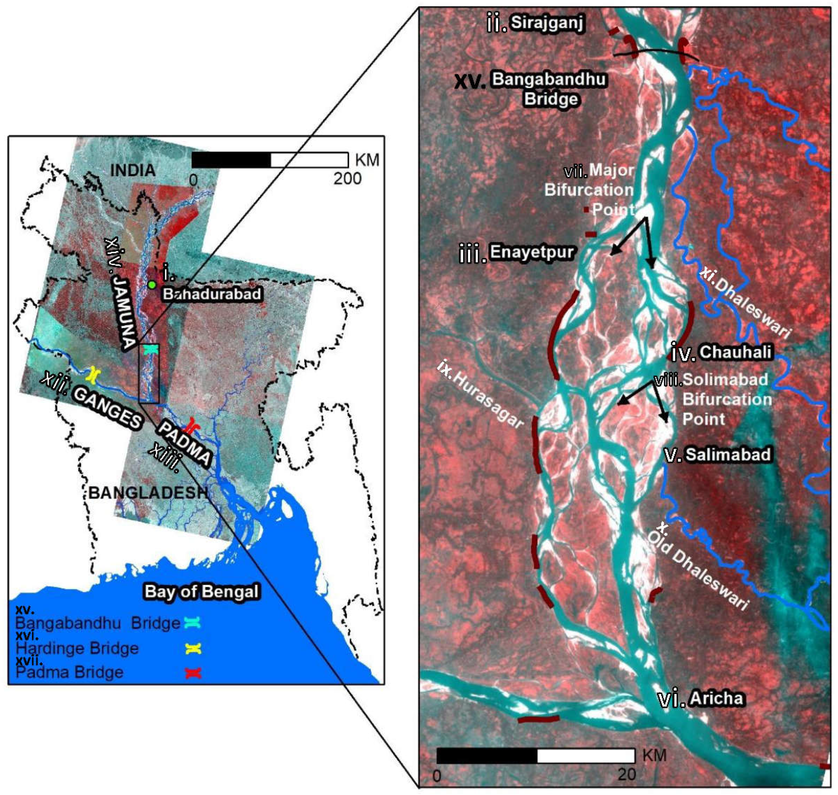
Figure 1. Study area (satellite image of January 2019, red lines show existing revetments). i. through vi. show key locations along the river system. vii. and viii. are the two major bifurcation points within the study area. ix. through xiv. are the key rivers within the study area. xv. through xvii. are the three major bridge crossings.
Geosciences 11 00389 g001
Figure 2. Satellite imagery from 2019 of the study area. Red lines on the map show ADCP measurement locations. Comparison between modeling and measured discharges (Q) as well as water levels (WL) at different branches and anabranches for the 2019 model are shown in the tables for each measurement location.
Geosciences 11 00389 g002
Figure 3. Stage–discharge relationships showing hysteresis effect for longer-term (left) and annual observation data (right) at Bahadurabad (labeled i. in Figure 1).
Geosciences 11 00389 g003
Figure 4. Water levels at Aricha (labeled vi. in Figure 1) in relation to the water levels at Bahadurabad (located on the Upper Jamuna, labeled i. in Figure 1), Sirajganj (located on the Upper Jamuna, labeled ii. in Figure 1) and the Hardinge Bridge (located on the Ganges, labeled xvi. in Figure 1).
Geosciences 11 00389 g004
Figure 5. Discharge (Q) distribution at the major bifurcation, labeled vii. in Figure 1 (left), and the Salimabad channel, labeled viii. in Figure 1, located at the left branch (right) (ADCP measurement locations as well as comparison with the model result are shown in Figure 2).
Geosciences 11 00389 g005
Figure 6. Discharge distribution for 2017 and 2019 models at the left branch (left) and the Salimabad channel (right) (ADCP measurement locations are shown in Figure 2).
Geosciences 11 00389 g006
Figure 7. Simulated discharge (Q) distribution at the bifurcation (left) and Salimabad (right) for different discharge conditions.
Geosciences 11 00389 g007
Figure 8. Bed topography measurements (in m +PWD) during 2011 and 2016–2019 showing changes in deep channels in upstream channel and branches (land boundary shows the planform of 2016).
Geosciences 11 00389 g008
Figure 9. Bed topography measurements (in m PWD) during 2015–2019 showing changes in deep channels and bend scour at Chauhali bend and Salimabad channel (land boundary shows the planform of 2016).
Geosciences 11 00389 g009
Figure 10. Water occurrence using JRC’s product (left) and NDWI average from raw images using MoMo (right) for 2019–2020.
Geosciences 11 00389 g010
Figure 11. Reach-average estimation of bed levels (b,c) and scour level (d) for selected reaches outlined in the upper-left plot (a) (the plotted bed topography data in (a) are from 2019).
Geosciences 11 00389 g011
Figure 12. Sedimentation and erosion, quantified by using MoMo for different periods (green and light-blue colors indicate sedimentation and erosion, respectively).
Geosciences 11 00389 g012
Figure 13. The satellite-derived differences for annual water occurrences computed using MoMo, showing deposition (green areas) and erosion (light-blue areas). Every image shows the difference in water occurrence between subsequent periods, so 2015–2014 corresponds to subtraction ῙNDWI (2015–2016) − ῙNDWI (2014–2015)).
Geosciences 11 00389 g013
Figure 14. Annual, 5-year and decadal changes in eroded (negative) and accreted (positive) areas (right) for the Lower Jamuna reach (left) from 2000 to 2019 (e.g., 2019–2018 corresponds to subtraction ῙNDWI (2019–2020) − ῙNDWI (2018–2019)) for different threshold values of water occurrence frequency for the (upper layer) (0%, 25%, 50% and 75%, respectively, as shown in (upper-right plot)).
Geosciences 11 00389 g014
Figure 15. Annual changes in eroded (negative) and accreted (positive) areas within selected reach (left) from 2010 to 2019 (e.g., 2019–2018 corresponds to subtraction ῙNDWI (2019–2020) − ῙNDWI (2018–2019)) for different threshold values of water occurrence frequency for the (upper layer) (0%, 25%, 50% and 75%, respectively, as shown in (upper left plot)).
Geosciences 11 00389 g015
Figure 16. Sedimentation and erosion during 2018–2019, simulated by the morphological model (left plot) and estimated as the difference between measured bed topography (projected on model grid) of 2018 and 2019 (right plot).
Geosciences 11 00389 g016
Figure 17. Simulated sedimentation and erosion during 2019–2020 (left plot) and 2020–2021 (right plot).
Geosciences 11 00389 g017
Table 1. Boundary conditions for verification run and simulation scenarios.
Simulation ScenarioUpstream Discharge (m3/s)Downstream Water Level (m + PWD)Remarks
Observed flow conditions35,7288.53Verification run (2019 bed topography)
10,3704.30
Low flow37372.56Scenarios for all 5 models with bed topography of 2011, 2016–2019 (5 × 5 = 25 simulations in total)
Average flow20,0006.50
Bankfull flow39,4219.22
5-year event74,2279.39
100-year event109,00010.50
Observed September 2018–September 2019Variable
(Hydrograph)
VariableMorphological verification
Observed September 2016–August 2017Variable
(Hydrograph)
VariableFuture morphological scenario
Publisher’s Note: MDPI stays neutral with regard to jurisdictional claims in published maps and institutional affiliations.