Stabilization of Landslides Sliding Layer Using Electrokinetic Phenomena and Vacuum Treatment
Abstract
1. Introduction
- Electroosmosis is based on the flow of ground water ions (diffusive and free) as a result of an electric field rising, caused by DC, in the direction from the anode to the cathode. Electroosmosis is the most important process for the successful dewatering of sediments.
- Electrophoresis depends on the displacement of negatively charged colloidal size particles of the soil environment from cathode to anode (anaphoresis) or of positively charged ones from anode to cathode (cataphoresis).
- Electromigration is the transport of ionic species in the pore fluid and is the main mechanism by which an electrical current flows through sediment. Electromigration also includes the movement of ions produced by electrolysis toward the oppositely charged electrode.
1.1. Applying Electrokinetic Phenomena to Soil Consolidation
1.1.1. Some of the Experiments Studied ET at Bench-Scale
1.1.2. Some Experiments Studied Effects of ET on the Theoretical and Numerical Models of the Soil
1.2. Vacuum Application for Soil Strengthening
1.3. Issues Related to the Control of Structural Landslides with a Determinate Slip Contact Layer
2. Description of the Processes Changing the Strength Parameters in the Soil Constituting the Flysch
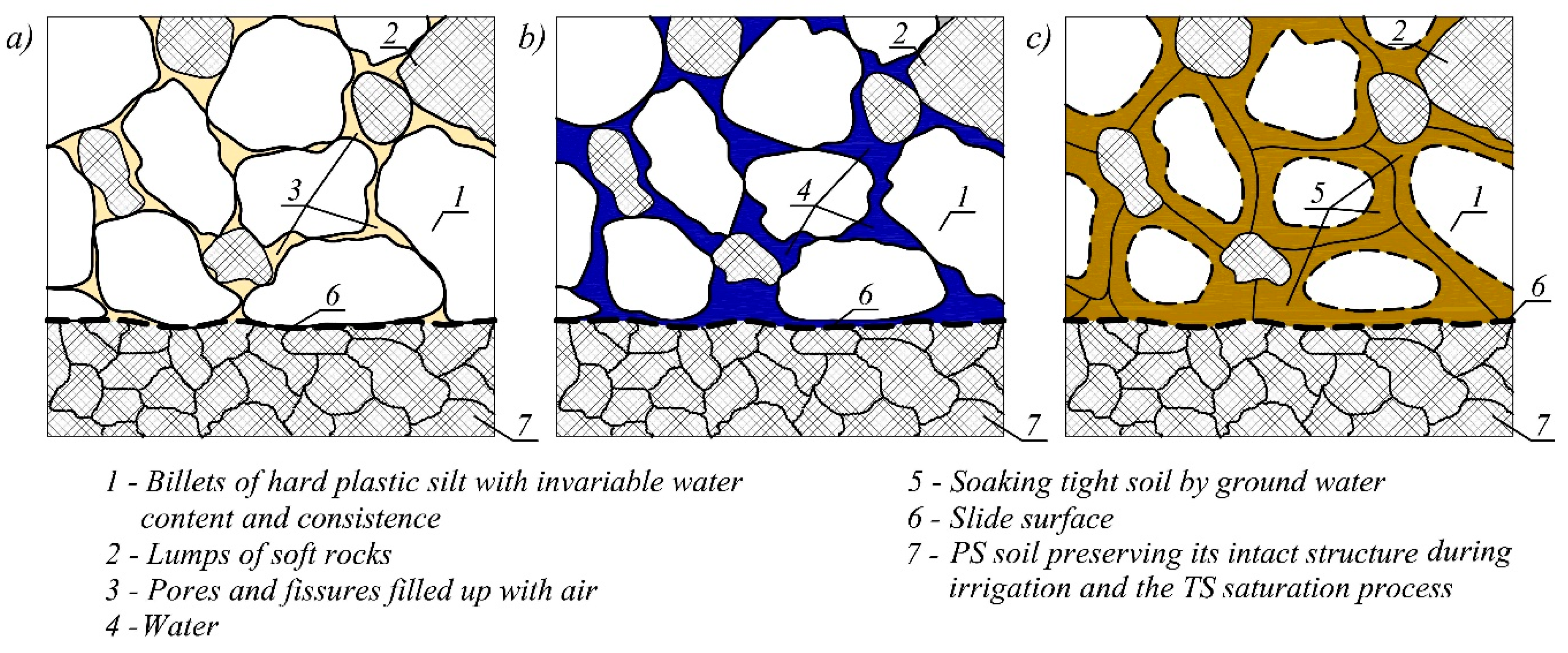
- Phase I, occurring in a long-lasting dry period or during light precipitation (Figure 3a). In this phase, the breccia and silt lumps conglomerated earlier and formed during erosion of the primary flysch layers lose a large amount of water content (moisture) and finally crack. As a result of drying, the strength parameters increase in the TS, causing its periodic stabilization.
- Phase II, occurring after long-lasting rainfall (Figure 3b). Precipitation water in this period penetrates the cracks that formed earlier. Ponds and sloughs form in terrain depressions (water hollows) supplying ground waters under pressure. This process causes the plastic state of silt soils to be bonding “not crumbled” TS lumps.
- Phase III, occurring after a long period of rainfall (Figure 3c). In this phase, bonding and silt lumps forming the landslide layer on their external layers undergo fluency. This causes the landslide section to behave as soft plastic soil in its entire thickness. This allows hard lumps in the plastic landslide mass to move and turn in spite of themselves.
- the real structure of the flysch formations in the existing landslide section,
- determination of the physical and mechanical parameters of the PS flysch forming the material of the TSs and in the contact layer near the slide plane,
- the geological structure of the intact rock base (the range of change of the hydrogeological and hydro technical conditions).
3. Study Methodology for Determining the Credible Physical and Mechanical Parameters
3.1. Initial Assumptions for the Studies
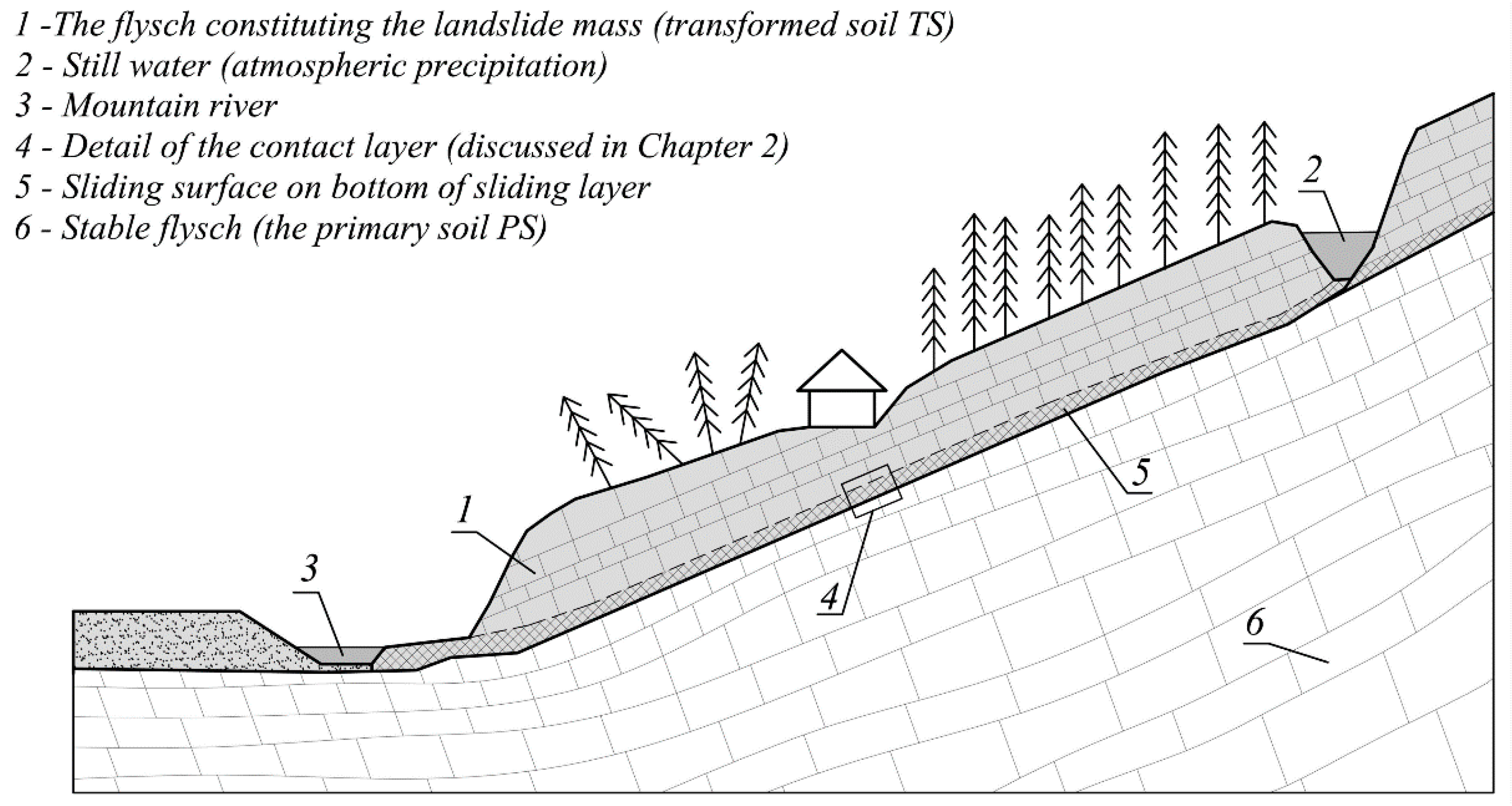
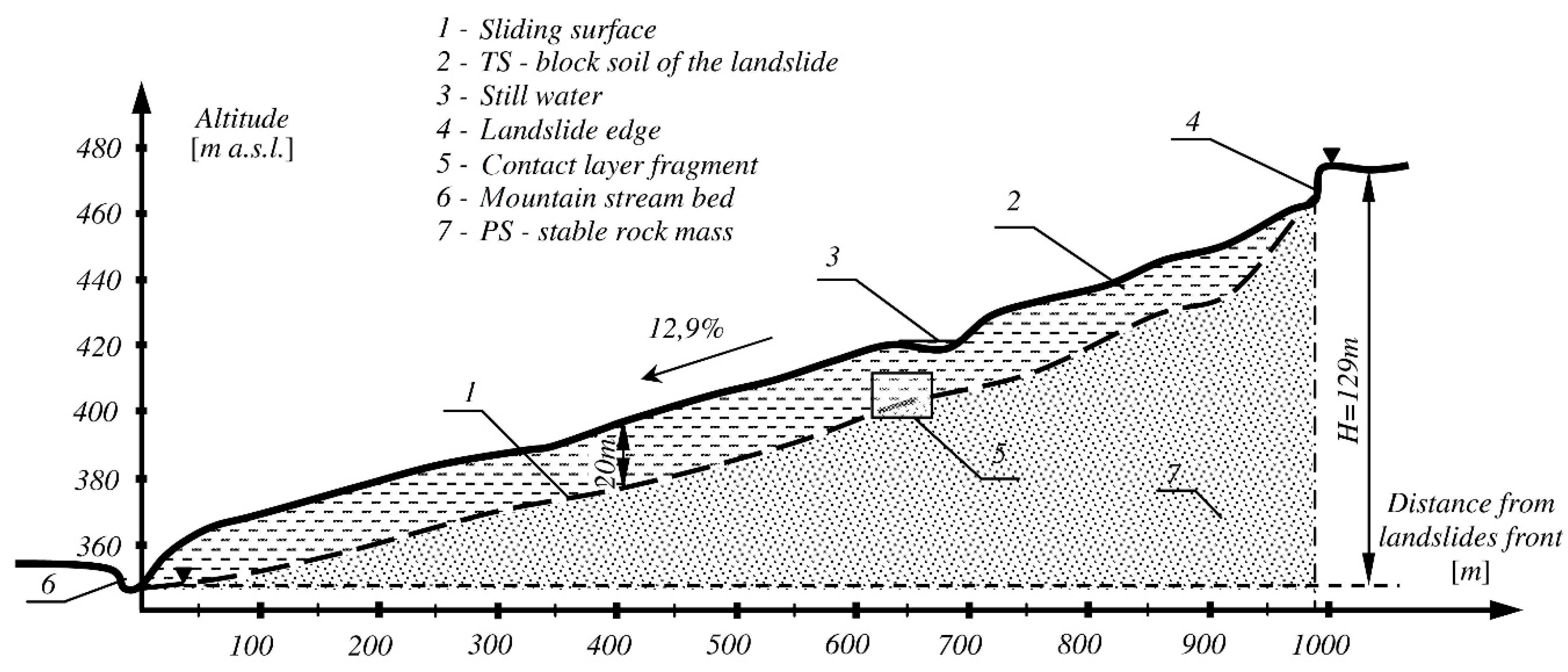
- consistent with the slope inclination of the stable base, on which a thick layer of weathered soft rock (to depth of 20 m) lies. The layer forming the landslide mass is usually composed of silts or dust clays including breccia and fragments of weathered soft rocks. Weak contact layers are formed from them, creating sliding surfaces that initiate landslides;
- the alternating level of the ground water table occurring in rock fissures of the cracked base. This water acts on the weathered soils with supplanting, filtration pressure, and hydrostatic pressure. It occurs in periods of long-lasting rain and snow melt, initiating the plastic state of the soil layers with a disturbed structure;
- static loads, such as the weight of municipal, engineering, hydrotechnical, and industrial structures, power objects, and woods. These objects ballast the wedge of a block soil in case of occurrence of such factors;
- deterministic and nondeterministic dynamic loads. They are caused by loads of roads and railways, heavy industrial and construction objects (pile drivers, hammers, turbines), seismic tremors, and even lightning tremors. They may constitute an impulse to start a landslide in the case of simultaneous hydration of the rock mass.
- the shaping of various forms of secondarily structured flysch soils;
- the action of the electrostatic field created by DC current flow causing soil stabilization. Interferences from the surrounding rock mass were eliminated. These interferences may cause uncontrolled current flow, which would exert a negative effect on the results of the studies;
- the vacuum dewatering of the rock mass with a known structure and the kind of the soil as well as the conditions of its hydration;
- the filtration conditions of the ground water in the flysch with a differential form of reconstructed structure;
- values of the variable normal stresses occurring in the contact layers at different depths of deposition.
- hydrated soils with a reconstructed structure demonstrate rheological features. They are characteristic for sticky materials demonstrating small values of internal friction ϕ and large values of the apparent cohesion variable c in time (the apparent cohesion occurring in large soil deformations under loads);
- exceeding the border value of static stresses causes the occurrence of displacements in the contact layer soils, which results from a lack of proper cohesion of this layer. Proper cohesion occurs only in soils that maintain a durable, stable structure under the influence of loads;
- due to a change in the water content and loosening of the solid phase, the studied soils may have a twofold form: regularly consolidated and over-consolidated soils. The regularly consolidated soils are those in which the cohesion was not able to take place after transformation as a result of water acting in the soaked soil (Figure 3, item 5). The over-consolidated soils are those that have effective cohesion after prior consolidation, which features lumps of the soil contact layer (Figure 3, item 1);
- the soils taking part in sliding processes, chiefly constituting the cover of the rock base, which were not subject to consolidation processes, are subject to the principles expressed by Bishop-Skempton and expressed by Wilun in 1982 [31] using the following formulas:
- for the consolidated regularly soilsτf = σ’tgϕ’,
- for the over-consolidated soilsIt was assumed that:τf = σ’tgϕ’ + c’,and therefore:
- for the consolidated regularly soils
- for the over-consolidated soilswhere: ϕ’ = effective angle of internal friction, c’ = effective cohesion, σ’ = σ − u = effective stresses in the solid phase at the moment of shearing, u = pore water pressure in a sample at the moment of shearing, Ψ = effective angle of internal friction corresponding to the maximal border inclination of the sliding surface. When the inclination of the landslide mass slide plane is larger than Ψ, it is assumed that shearing of this contact layer will occur, initiating sliding.
- (a)
- the examined sample is submitted to consolidation at normal stress σ,
- (b)
- next, the constant shearing tension τ is applied and the displacement s is determined until it disappears, measuring the increase of deformation η s/t (where s = displacement in time t and t = the time in which the displacement occurs s),
- (c)
- when η reaches a value close to 0, the test is considered finished and the displacement s is the “way of mobilization” of the soil for shearing.
3.2. Selection of the Method of Determining the Physical and Mechanical Parameters of the TS
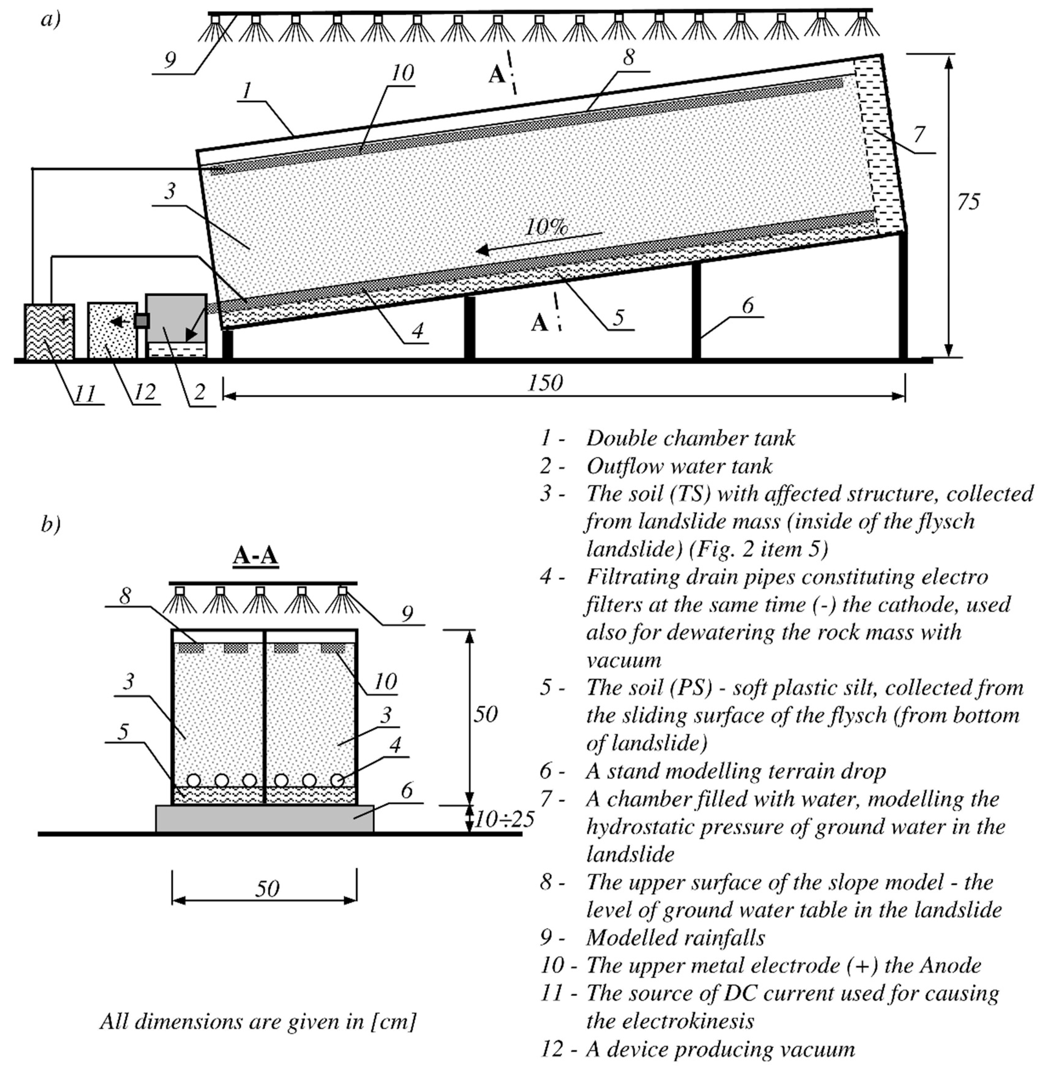
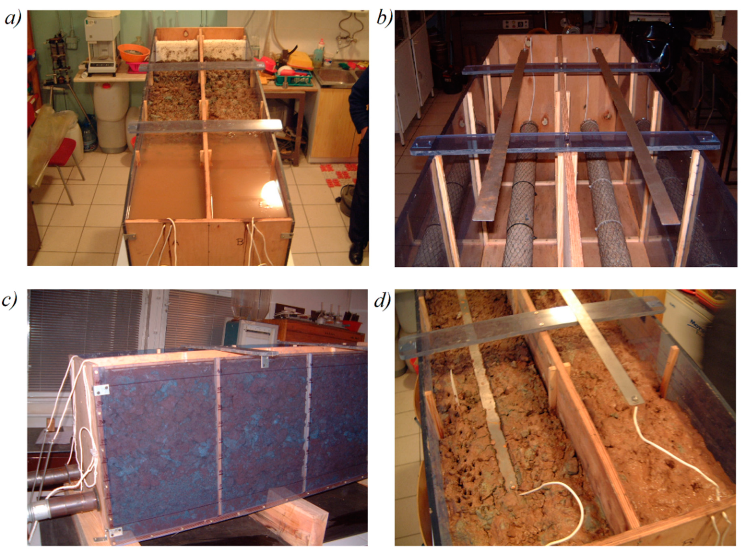
3.3. Description of the Test Model and Testing Process
- (a)
- soil homogenization and removal of oversized particles,
- (b)
- filling of the chamber spaces with the test soil in layers with thicknesses of approximately 10 cm,
- (c)
- systematic compaction on the whole surface of each layer with a compactor (approximately 3.5 kg) falling from 20 cm height,
- (d)
- protection of the stand against drying,
- (e)
- verification of the soil parameters ϕ, c, and γ in the initial state of the tests with respect to the soil located in the deposit.
- (a)
- gravitational dewatering and dewatering in which the ET process is also applied,
- (b)
- gravitational dewatering and dewatering in which a vacuum is also applied,
- (c)
- dewatering in which the ET process is applied and dewatering by application of a vacuum.
- gravitational drainage,
- electrodes in the ET process (cathode (–)),
- ducts for the generation of a vacuum in the soil (suctioning both water and air from the soil pores).
- σ1 = 100 mm,
- σ2 = 200 mm,
- σ3 = 300 mm,
- σ4 = 400 mm.
4. Analysis and Discussion of Test Results
- (a)
- Borowicka—in the Direct Shear Test Apparatus,
- (b)
- Kezdi—in the Direct Shear Test Apparatus,
- (c)
- In the Triaxial Shear Test Apparatus.
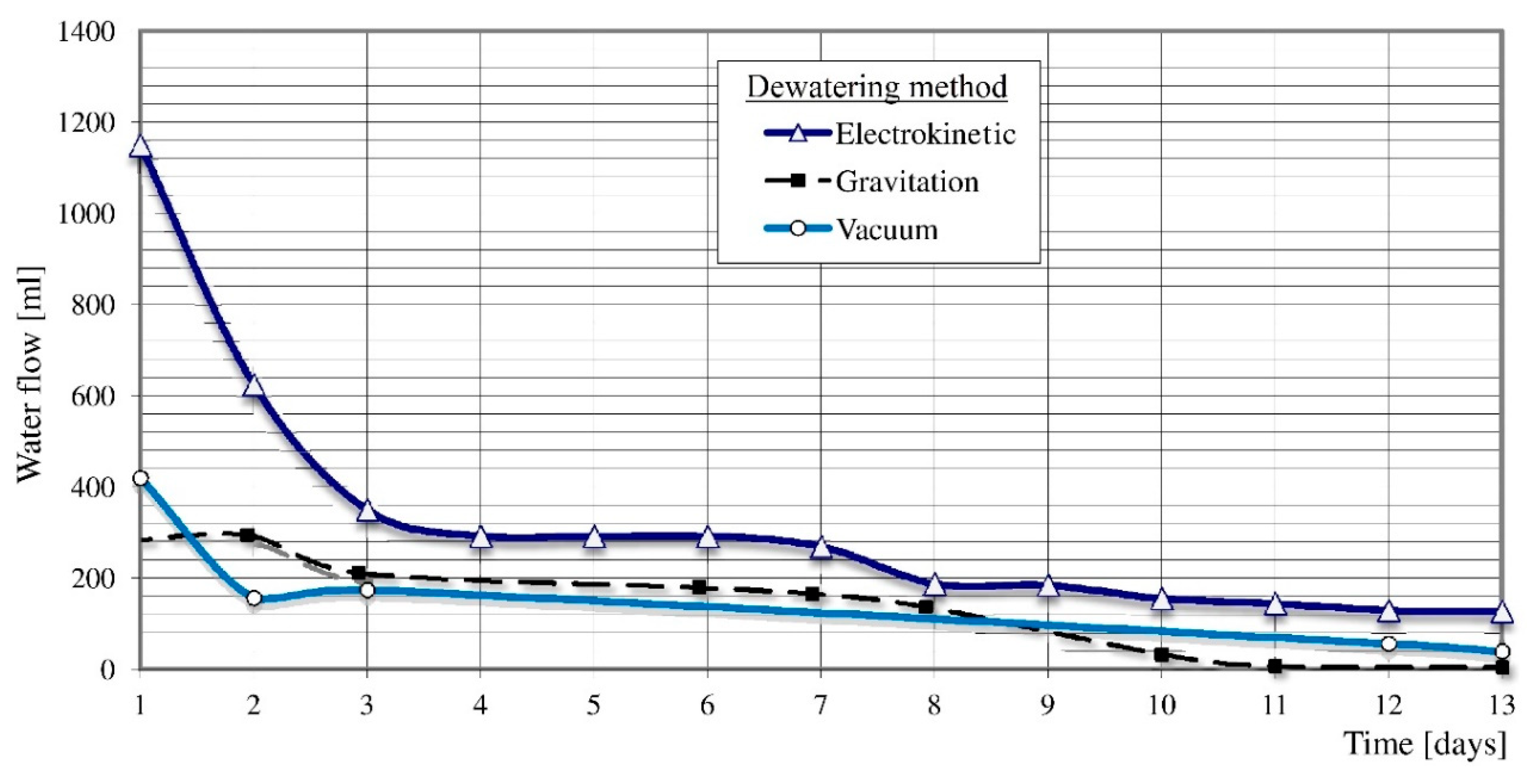
4.1. Comparative Studies of Intensity of Leaks from the TS
- (a)
- the water outflow intensity from drainpipes during soil dewatering is highest by far with the electrokinetic method, especially in the early phase (the first three days).
- (b)
- The results of outflow intensity studies of the vacuum method are comparable with those of the gravitational method. It must be mentioned, though, that after approximately 11 days the gravitational outflows stop, while those obtained by the vacuum method last much longer.
- (c)
- soil dewatering using the gravitational and electrokinetic methods demonstrates constant outflows during the whole period of tests. Meanwhile, when using the vacuum method, outflows occur intensively for a short time (a few hours) and then stop. Starting the vacuum in cycles leads to renewed, intensive, short outflows.
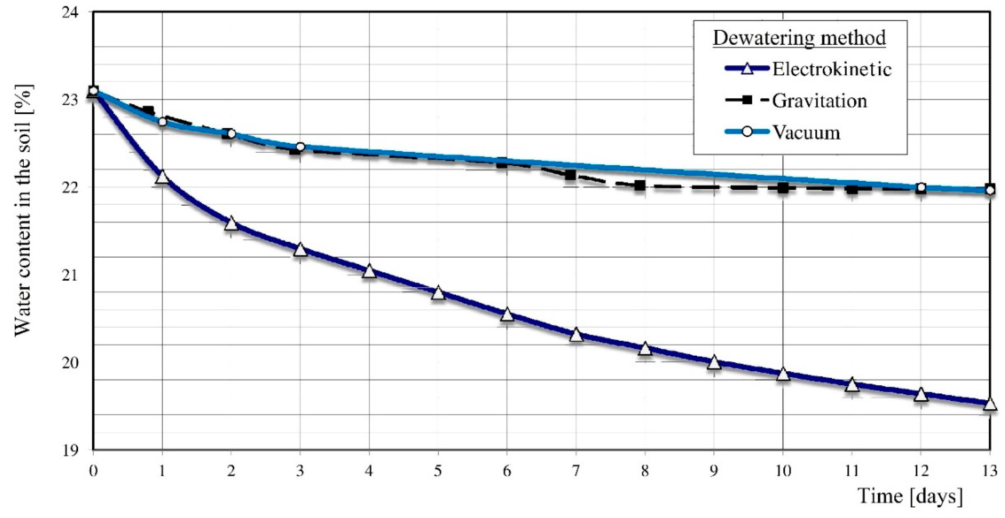
4.2. Tests of Water Content Changes in the TS
- using the electrokinetic method, a 4.6% reduction in the soil water content was obtained (during 14 days),
- at the same time, using the vacuum and gravitational methods, the soil water content decreased by 1.1%,
- using the gravitational method, the soil water content stabilized at a constant level. Meanwhile, with the remaining dewatering methods, especially the electrokinetic method, it decreased continually.
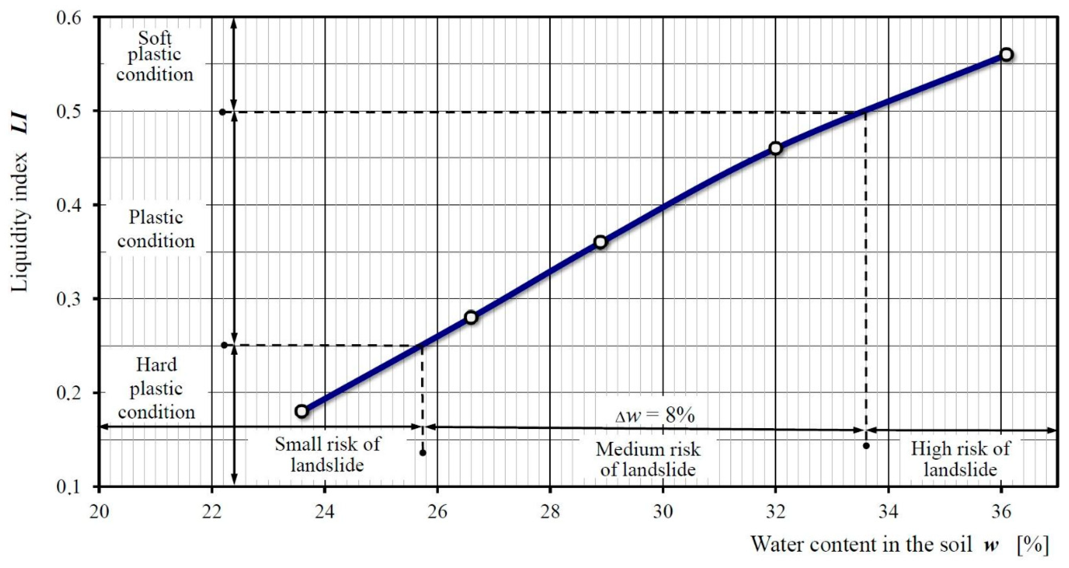
4.3. Determining the Relation Between the Risk Of Landslide Formation under the TS Condition and Its Water Content
- the soil in the plastic condition behaves in the way determined in Figure 3b—there may be a risk of landslide occurrence, which increases with the drop of the liquidity index,
- the soil in the soft plastic condition behaves in the way determined in Figure 3c—there is a high probability of landslide occurrence, because the mechanism of slide occurrence may be initiated easily.
- (a)
- hard plastic in the water content ranges below 26%,
- (b)
- plastic in the water content ranges 26–34%,
- (c)
- soft plastic in the water content ranges above 34%.
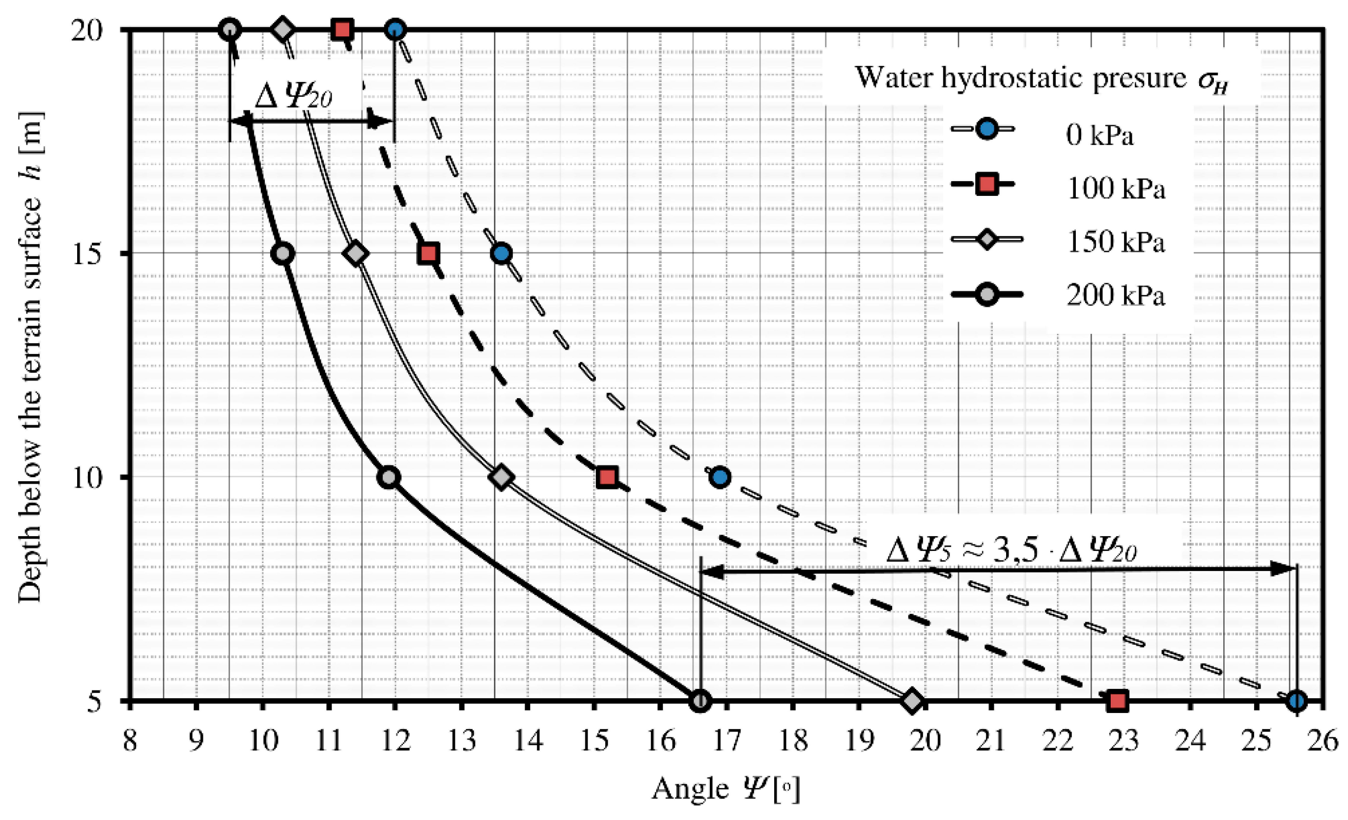
4.4. Determination of the Influence of Water Pressure on the TS Strength Parameters
- the value of Ψ (determined from Equations (4) and (5)) depends on the depth of location of the slide layer; that is, Ψ decreases with depth of deposition of the contact layer;
- with increases in the thickness of the TS layer, the hydrostatic pressure σH grows, exerting pressure on the underside of the block soil, leading to changes in the value of Ψ’?
- with depth and increase of the hydrostatic pressure σH we observe an increase of ∆Ψ, namely growth of the effective angle of internal friction ∆Ψ (even 3,5 times—Figure 10).
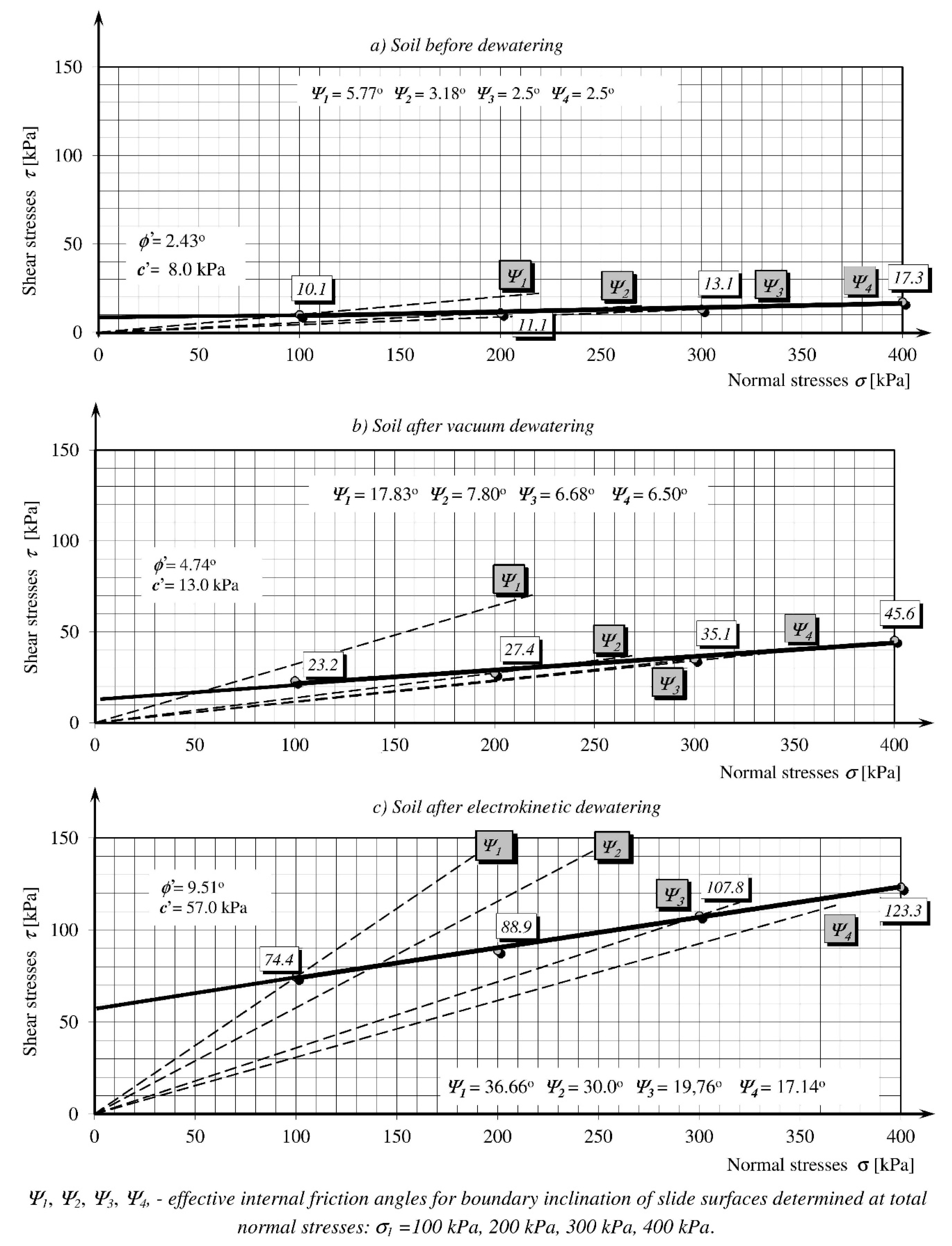
4.5. Determining the Effectiveness of Growth of Soil Strength Parameters after Dewatering
- in the case of both methods, in the range of the internal friction effective angle ϕ’ and cohesion c’, decisive increases of these parameters take place for the samples from the contact layer,
- the effective soil parameters after dewatering (ϕ’r, c’, and Ψ1) increase substantially with respect to the soil before dewatering (ϕ’°, c’°, and Ψ1°). Comparing the values Ψ1° and Ψ1, it can be seen that the internal friction effective angles, corresponding to the maximal border inclination of the sliding surfaces, increase approximately three times with the vacuum method and approximately six times with the electrokinetic method (Table 1 and Table 2).
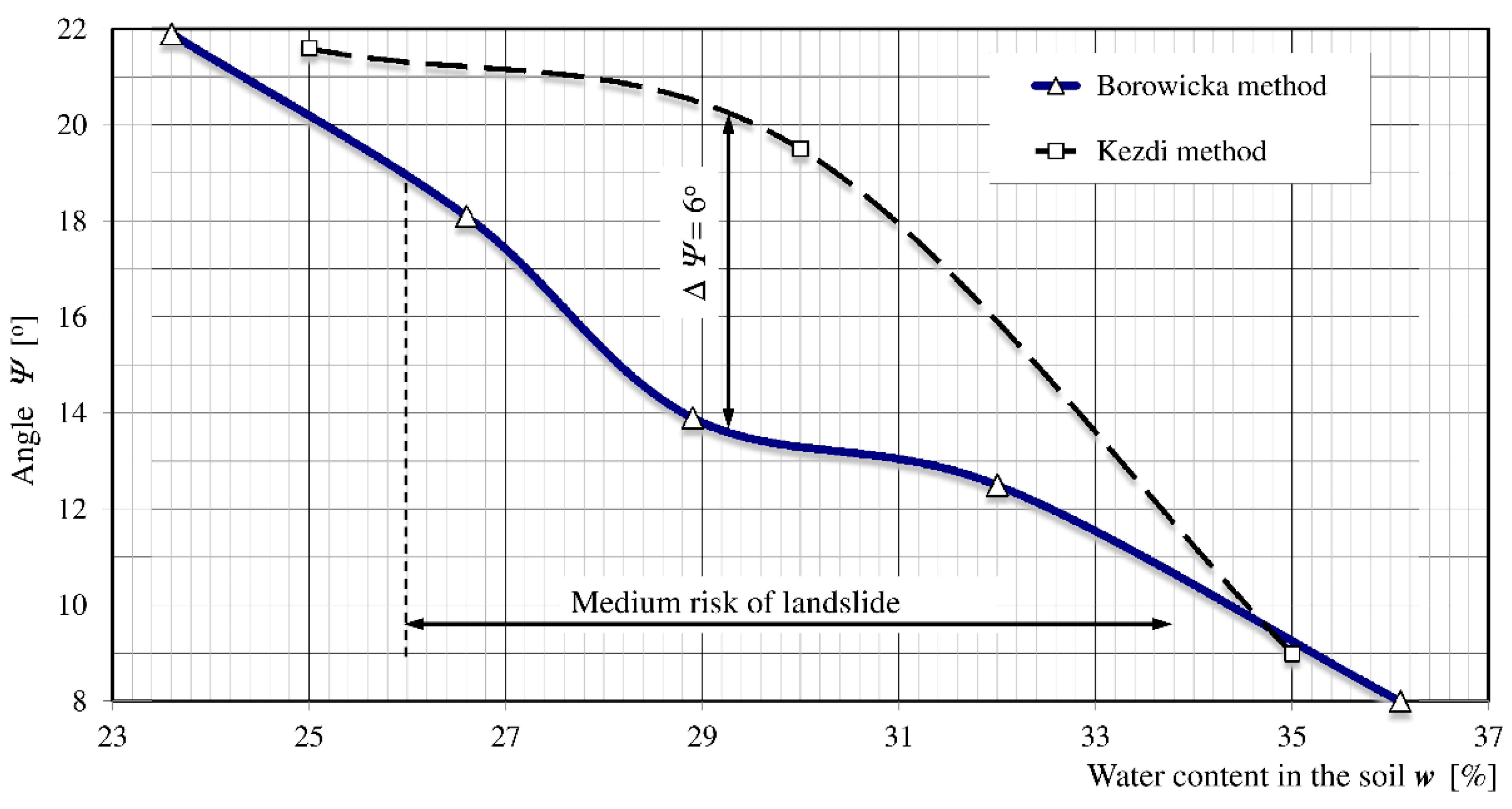
4.6. Comparison of the Influence of The Selected Method in the TS Study on the Final Results
- for LI = 0.5–0.25, that is, w = 26.0–33.6%, covering the soil plasticity condition (medium risk of landslide), the largest differences between the two methods occur,
- the results obtained by the Kezdi method with respect to the angle Ψ are 2°–6° higher than those obtained by the Borowicki method,
- the Borowicka method is safer for analyzing the sliding surface of the contact layer in the direct soil shearing box apparatus,
- in the examined soil, the Borowicka method gives safer results than the Kezdi method in the range of soil water contents of 24–35%.
5. Conclusions
- The condition of the contact layer soil (forming the sliding surfaces) is decisive for the initiation of the landslide. The water content in the contact layer soil has a large influence on the condition of the soil (defined by the liquidity index). Reducing the soil water content causes an increase in strength of the soil wall and an increase in the stability of the landslide mass. Thus, controlling the soil water content is crucial for gaining control over landslides in cohesive soils.
- The analysis of soils forming the slide zone of the contact layer conducted by the Borowicka method provides safer results than the Kezdi method, especially for soils in plastic condition.
- The range of change of water content in the examined TS, wherein the soil condition passes from safe (small risk of stability loss) to the hazardous state, is approximately 8%. The electrokinetic method diminishes the water content in the soil by approximately 4.6% within two weeks. Therefore, it can be assumed (taking into account the recorded stability of the dewatering effect) that application of this method during a period of approximately four weeks will provide scarp stability or stabilization of an active landslide by correction of the physical and mechanical parameters of the contact layer. Obtaining such a state of the soil is possible provided that no water can flow to the contact layer soil. This can be achieved by correct execution of the intake and draining of rainwater to outside of the landslide.
- Although the vacuum method demonstrates ability to dewater the soil comparable to the gravitational outflow, it is far less effective than the electrokinetic method. Therefore, it can be recommended only as the supporting method, especially at the soil injection.
- Variability of the effective internal friction angle corresponding to the maximal border inclination of sliding surfaces Ψ clearly depends on the depth at which the contact layer occurs, normal stresses in the soil, and hydrostatic pressure occurring at the level of the slide surface. With increases in depth and the value of hydrostatic pressure acting on the landslide block soil, the value of Ψ diminishes.
- Applications of the electrokinetic or electrokinetic-vacuum method of dewatering the soil are effective. They lead to beneficial stabilization processes and may be used effectively for stabilization of landslides. The condition of their application is effective intake of rainwater at a level that ensures safe control of the ground water level during periods of precipitation.
- In cases of the need for less important landslide counter reacting, protective works may be limited to efficient intake of surface water and outflows of depth water as well as gravitational dewatering. It is also possible to apply a combination of the methods discussed above, selected with reference to the terrain conditions and geological structure of the area analyzed with respect to stability.
Funding
Acknowledgments
Conflicts of Interest
References
- Horvitz, W. The theory of electrokinetic phenomena. J. Chem. Educ. 1939, 16, 519–535. [Google Scholar] [CrossRef]
- Casagrande, L. Electro-osmosis in soils. Geotechnique 1949, 1, 159–177. [Google Scholar] [CrossRef]
- Casagrande, L.; Longhney, R.W.; Matich, A.J. Elektro-Osmotic Stabilization of a High Slope. In Proceedings of the 5th Intnational Conference on Soli Mechanics and Foundation Engineering, Paris, Franch, 17–22 July 1961; Volume 1. [Google Scholar]
- Ukleja, K. Electroosmotic Drying of Slime Consistence Wastes; Industrial Enviromental Research Laboratory, US EPA: Cincinnati, OH, USA, 1972; p. 210.
- Lo, K.Y.; Ho, K.S.; Inculet, I.I. Field test of electroosmotic strengthening of soft sensitive clay. Can. Geotech. J. 1991, 28, 74–83. [Google Scholar] [CrossRef]
- Lo, K.Y.; Inculet, I.I.; Ho, K.S. Electroosmotic strengthening of soft sensitive clay. Can. Geotech. J. 1991, 28, 62–73. [Google Scholar] [CrossRef]
- Hong, H.P.; Shang, J.Q. Probabilistic analysis of consolidation with prefabricated vertical drains for soil improvement. Can. Geotech. J. 1998, 35, 666–677. [Google Scholar] [CrossRef]
- Chen, J.L.; Murdoch, L. Effects of electroosmosis on natural soil: Field test. J. Geotech. Geoenviron. Eng. 1999, 125, 1090–1098. [Google Scholar] [CrossRef]
- Mohamedelhassan, E.; Shang, J.Q. Effects of electrode materials and current intermittence in electro-osmosis. Ground. Improv. 2001, 5, 3–11. [Google Scholar] [CrossRef]
- Glendinning, S.; Jones, C.J.; Pugh, R.C. Reinforced soil using cohesive fill and electrokinetic geosynthetics. Int. J. Geomechanics 2005, 5, 138–146. [Google Scholar] [CrossRef]
- Reddy, K.R.; Urbanek, A.; Khodadoust, A.P. Electroosmotic dewatering of dredged sediments: Bench-scale investigation. J. Environ. Manag. 2006, 78, 200–208. [Google Scholar] [CrossRef]
- Su, J.Q.; Wang, Z. The two-dimensional consolidation theory of electro-osmosis. Geotechnique 2003, 53, 759–763. [Google Scholar] [CrossRef]
- Gabrieli, L.; Alshawabkeh, A.N. Influence of boundary conditions on transient excess pore pressure during electrokinetic applications in soils. J. Appl. Electrochem. 2010, 40, 1113–1121. [Google Scholar] [CrossRef]
- Deng, A.; Zhou, Y. A Piecewise-Linear Numerical Model for One-Dimensional Electroosmosis Consolidation. In Proceedings of the International Conference on Ground Improvement (ICGI 2012), Wollongong, Australia, 30 October–2 November 2012; pp. 1369–1375. [Google Scholar]
- Zhou, Y.; Deng, A.; Wang, C. Finite-difference model for one-dimensional electro-osmotic consolidation. Comput. Geotech. 2013, 54, 152–165. [Google Scholar] [CrossRef]
- Al-Hamdan, A.Z.; Reddy, K.R. Electrokinetic remediation modelling incorporating geochemical effects. J. Geotech. Geoenviron. Eng. 2008, 134, 91–105. [Google Scholar] [CrossRef]
- Gargano, S.; Lirer, S.; Flora, A. Analysis of the coupled electro-osmotic and mechanical consolidation in clayey soils. Proc. Inst. Civ. Eng. Ground Improv. 2019, 172, 146–157. [Google Scholar] [CrossRef]
- Gargano, S.; Lirer, S.; Flora, A. Mechanical and Physical Effects of Electroosmotic Dewatering of Clayey Soils. In National Conference of the Researchers of Geotechnical Engineering; Calvetti, F., Ed.; Springer: Cham, Switzerland, 2020; pp. 387–396. [Google Scholar] [CrossRef]
- Shang, J.Q.; Tang, M.; Miao, Z. Vacuum preloading consolidation of reclaimed land: A case study. Can. Geotech. J. 1998, 35, 740–749. [Google Scholar] [CrossRef]
- Deng, A.; Xu, S. Consolidating Dredge Soil by Combining Vacuum and Dynamic Compaction Effort. In Ground Improvement and Geosynthetics; American Society of Civil Engineers: Reston, VA, USA, 2010; pp. 113–118. [Google Scholar]
- Li, L.H.; Wang, Q.; Wang, J.; Wang, N. Analysis of stress path soils deformation under the vacuum drainage preloading. J. Eng. Geol. 2001, 9, 170–173. [Google Scholar]
- Li, L.H.; Wang, Q.; Wang, N.X.; Wang, J.P. Vacuum dewatering and horizontal drainage blankets: A method for layered soil reclamation. Bull. Eng. Geol. Environ. 2009, 68, 277–285. [Google Scholar] [CrossRef]
- Wu, H.; Hu, L. Theoretical Analysis and Numerical Simulation of Vacuum Preloading in Combination with Electro-osmosis Consolidation. In Proceedings of the Conference Paper Geo-Frontiers 2011, Dallas, TX, USA, 13–16 March 2011. [Google Scholar]
- Lian-Heng, Z.; Jingyuan, C.; Yingbin, Z.; Qiang, L. Effect of hydraulic distribution on the stability of a plane slide rock slope under the nonlinear Barton-Bandis failure criterion. Geomech. Eng. 2015, 8, 391–414. [Google Scholar]
- Jian, J.; Hong-Jian, L. Sensitivity-based reliability analysis of earth slopes using finite element method. Geomech. Eng. 2014, 6, 545–560. [Google Scholar]
- Kuangmin, W.; Sheng, Z. Application of an elastoplastic model to predict behaviors of Concrete-Faced Rock-fill Dam under complex loading conditions. J. Civ. Eng. Manag. 2015, 21, 854–865. [Google Scholar]
- Jiuping, X.; Cuiying, F. Two-stage based dynamic earth-rock transportation assignment problem under fuzzy random environment to earth-rock dam construction. J. Civ. Eng. Manag. 2015, 21, 775–797. [Google Scholar]
- Poisel, R.; Angerer, H.; Pöllinger, M.; Kalcher, T.; Kittl, H. Mechanics and velocity of the Lärchberg–Galgenwald landslide (Austria). Eng. Geol. 2009, 109, 57–66. [Google Scholar] [CrossRef]
- Al-Homoud, A.S.; Tal, A.B.; Taqieddin, S.A. A comparative study of slope stability methods and mitigative design of a highway embankment landslide with a potential for deep seated sliding. Eng. Geol. 1997, 47, 157–173. [Google Scholar] [CrossRef]
- Salcedo, D.A. Behavior of a landslide prior to inducing a viaduct failure, Caracas–La Guaira highway, Venezuela. Eng. Geol. 2009, 109, 16–30. [Google Scholar] [CrossRef]
- Wilun, Z. Outline of the Geotechnics; Wydawnictwo Komunikacji i Lacznosci: Warsaw, Poland, 1982; pp. 194–199. [Google Scholar]
- Borowicka, H. Uber Die Scherfestigkeit Bindiger Boden; Mitt.des Instituts fur Grundbau und Bodenmechanik: Wien, Austria, 1961. [Google Scholar]
- Kezdi, A. Erddrucktheorien; Springer: Berlin/Heidelberg, Germany, 1962. [Google Scholar]
- Ukleja, J.; Ukleja, K. Increasing of Soil Slide Stabilization Using Forced Dewatering by Vacuum and Electrokinetic Phenomena. In Proceedings of the Conference on Geotechnic and Special Construction, Krakow, Poland, 12 May 2006; pp. 519–535. [Google Scholar]
| Parameter | TS Soil Parameter | Increase [%] | |
|---|---|---|---|
| Before Dewatering | After Dewatering | ||
| c’ [kPa] | 8.0 | 13.0 | 62.5 |
| ϕ’ [°] | 2.43 | 4.73 | 94.7 |
| Ψ1 [°] | 5.77 | 17.83 | 209.0 |
| Parameter | TS Soil Parameter | Increase [%] | |
|---|---|---|---|
| Before Dewatering | After Dewatering | ||
| c’ [kPa] | 8.0 | 57.0 | 612.5 |
| ϕ’ [°] | 2.43 | 9.51 | 291.4 |
| Ψ1 [°] | 5.77 | 36.66 | 535.4 |
© 2020 by the author. Licensee MDPI, Basel, Switzerland. This article is an open access article distributed under the terms and conditions of the Creative Commons Attribution (CC BY) license (http://creativecommons.org/licenses/by/4.0/).
Share and Cite
Ukleja, J. Stabilization of Landslides Sliding Layer Using Electrokinetic Phenomena and Vacuum Treatment. Geosciences 2020, 10, 284. https://doi.org/10.3390/geosciences10080284
Ukleja J. Stabilization of Landslides Sliding Layer Using Electrokinetic Phenomena and Vacuum Treatment. Geosciences. 2020; 10(8):284. https://doi.org/10.3390/geosciences10080284
Chicago/Turabian StyleUkleja, Janusz. 2020. "Stabilization of Landslides Sliding Layer Using Electrokinetic Phenomena and Vacuum Treatment" Geosciences 10, no. 8: 284. https://doi.org/10.3390/geosciences10080284
APA StyleUkleja, J. (2020). Stabilization of Landslides Sliding Layer Using Electrokinetic Phenomena and Vacuum Treatment. Geosciences, 10(8), 284. https://doi.org/10.3390/geosciences10080284


