Article

Seismic Characteristics and Development of the Upper Jurassic Carbonate Buildups from the Miechów Trough (Southern Poland)

Institute of Geological Sciences, Polish Academy of Sciences, Twarda 51/55, PL-00-818 Warszawa, Poland
*
Author to whom correspondence should be addressed.
Geosciences 2020, 10(6), 239; https://doi.org/10.3390/geosciences10060239
Submission received: 30 April 2020 / Revised: 14 June 2020 / Accepted: 16 June 2020 / Published: 18 June 2020
(This article belongs to the Section Geophysics)

Abstract

:
The presented study is devoted to the subsurface Upper Jurassic carbonate buildups and surrounding stratified inter-buildup deposits in the hitherto less recognized area, in comparison with other parts of the northern Tethyan shelf in Poland and Europe. The study area is located within the present-day Miechów Trough, almost entirely covered by thick Cretaceous and younger deposits. This paper shows results of the interpretation of 2D seismic data, calibrated by data from deep wells. Investigation of various elements of the Upper Jurassic carbonate depositional system in the Miechów Trough is supported by seismic facies and attribute analysis. The four distinctive seismic facies—(A) bedded, (B) mound-shaped, (C) contorted-chaotic, and (D) chaotic—were assigned to the main Upper Jurassic sedimentary facies, represented by (1) bedded facies, (2) massive facies (carbonate buildups) and (3) deposits of gravity mass-flows. The results of this study were used to construct a depositional model for the Upper Jurassic succession, that focuses on the initiation, growth and demise of the large carbonate buildups in this part of the basin. This paper also presents the more extensive distribution of the Upper Jurassic carbonate buildups than was previously proposed for the Miechów Trough.

1. Introduction

In the Late Jurassic, widespread development of carbonate buildups occurred in Europe, particularly on the northern Tethyan shelf (e.g., [1,2,3,4,5]), which presently extends from Portugal to Spain, France, Switzerland, southern Germany, Poland to Romania, and further east towards the Crimea and Caucasus (e.g., [6,7,8,9,10]). The broad paleogeographical distribution of the Upper Jurassic carbonate buildups reflects mainly (1) important global changes of the paleo-tectonic regime, caused by the final break-up of Pangea and related regional paleo-tectonic changes along the continental margins and adjacent shelf areas, (2) high global sea-level in the Late Jurassic, as well as the influence of regional or local rise or falls in sea level on the carbonate sedimentation, and (3) significant changes of paleoclimate, paleoecology, etc. (e.g., [1,5,11,12,13,14]; cf., [15]).
The Upper Jurassic carbonate buildups of the northern Tethys shelf developed on extensive ramp-type platforms (e.g., [6,16,17]), and their differentiated deposits could be divided into three main compositional types: (1) coral-dominated, (2) siliceous sponge-dominated, and (3) microbialite-dominated (e.g., [3,4,5,6,8]). Intensive growth of the carbonate buildups took place mainly during the Oxfordian, sometimes up to the Kimmeridgian; in some basins, however, they might have developed locally even up to the Tithonian (e.g., [4,6,8,18,19,20,21,22]). The microbial crusts (see e.g., [23,24,25] for more details concerning microbial structures) play important roles not only within the microbial facies, but also in the sponge and coral facies, where they occur in variable quantities ([1]; see also [26,27]). The large and complex structures often developed as diverse microbial-sponge buildups, with a well-pronounced so-called rigid framework [4,28]. Such carbonate buildups, characterized by their present-day observed significant cumulative heights, reaching dozens of meters, are suited for identification and interpretation using seismic data (see e.g., [29,30,31,32,33,34,35,36,37,38]).
Because of certain limitations of reflection seismic data, related to the vertical resolution of seismic signal (e.g., [39]), seismic interpretation methods can be applicable only for the detection of relatively large and complex structures, characterized by heights exceeding the limits of vertical resolution. For the seismically interpreted Upper Jurassic strata in southern Poland, the vertical signal resolution is usually in the order of 10–30 m [22,40,41,42,43]. Thus, carbonate buildups of at least such heights could be identified on seismic data (cf., [40]).
During the last few decades, seismic data analysis proved its applicability in the analysis of carbonate depositional systems, due to its ability to detect lateral facies’ changes from massive organic buildups into surrounding stratified deposits, which are related to variations of the seismic reflection patterns or so-called lateral seismic facies changes (for more details see, e.g., [44]). Depositional features such as carbonate buildups can be often clearly visible on seismic data because of significant velocity and density contrasts between different lithological types of carbonate rocks (e.g., contrast between massive, reef limestones, bedded limestone and marls deposits), as evident from numerous recently published papers dedicated to different aspects of the seismic interpretation of carbonate buildups of different ages, and from various sedimentary basins (e.g., [37,38,45,46,47,48,49,50,51,52,53]).
The Upper Jurassic carbonate buildups from the northern Tethyan shelf and adjacent areas were also investigated using seismic data; however, a relatively small number of seismic interpretation studies have been published to date (e.g., [54,55,56,57]). Additionally, previous studies of the Upper Jurassic carbonate buildups from southern Poland, based on seismic data, have been usually published in local journals, with limited availability to international readership [22,40,41,42,58,59,60,61,62,63,64,65].
Seismic interpretation methods are an indispensable tool for the recognition and interpretation of carbonate buildups and the surrounding deposits along these parts of the northern Tethyan shelf margin, as well as in adjacent areas in Europe where the Upper Jurassic deposits are covered by younger deposits and thus no outcrops are available. This paper fills this gap, and provides results of the seismic interpretation of the subsurface Upper Jurassic carbonate buildups from the Miechów Trough, southern Poland, where the Upper Jurassic rocks are almost fully covered by thick Cretaceous and younger strata ([66,67]; Figure 1). The Upper Jurassic succession in the Miechów Trough remains relatively poorly recognized in comparison with the other parts of the Jurassic basin in Poland and western-central Europe, especially in comparison to adjacent areas of the Kraków-Częstochowa Upland, and the south-western margin of the Holy Cross Mountains, where the carbonate buildups are well-known from numerous outcrops (e.g., [27,28,68,69,70]).
During the Late Jurassic, southern Poland formed an open shelf, or gently inclined carbonate ramp, that connected the epicontinental sea with Tethyan basins (cf., [28,71,72]). The study area is located within the central part of the Miechów Trough, approximately 50 km north-east from the city of Kraków (Figure 1). The Upper Jurassic succession in the study area was drilled in 2011 by two exploratory wells, which, together with three legacy wells, have been used to calibrate the 2D seismic reflection data. In our previously published paper [43], we presented seismic evidence for a system of large carbonate buildups identified in this part of the basin. The aim of this paper is to present results of a more detailed study of the Upper Jurassic carbonate buildups and surrounding stratified inter-buildup deposits, based on seismic facies and seismic attribute analysis. Results of those studies were used to construct a depositional model for the Upper Jurassic succession, which summarizes current knowledge derived from numerous studies, mostly based on outcrops integrated with results of the analysis of the subsurface data (seismic and wells). Finally, an updated Late Jurassic paleogeographic map for southern Poland and adjacent areas is presented, emphasizing a much more extensive distribution of the Upper Jurassic carbonate buildups than previously proposed.

2. Geological Setting

2.1. The Permian–Mesozoic Polish Basin

The study area is located in the Miechów Trough (Figure 1), which belongs to the south-eastern part of the Szczecin-Łódź-Miechów Synclinorium [73] that developed during the Late Cretaceous–Paleogene inversion of the Permian–Mesozoic Polish Basin. This basin formed the easternmost part of a system of epicontinental basins of western and central Europe [74,75,76]. Its most subsiding axial part—the Mid-Polish Trough—evolved along the NW–SE-trending Teisseyre-Tornquist Zone (see [77] for a recent summary and further references). The south-eastern part of the basin extended into the transition zone towards the Tethyan Ocean. Since the Jurassic, the thickness and depositional pattern in this part of the basin has been influenced by increased regional subsidence in the Tethyan domain, and also by tectonic processes acting within the Polish Basin [78,79,80,81,82,83,84,85]. The Polish Basin was inverted during the Late Cretaceous–Paleogene (e.g., [85,86,87,88]). This inversion was related to substantial uplift and erosion of its axial part, which was transformed into a regional anticlinal structure—the Mid-Polish Swell (Mid-Polish Anticlinorium; cf., [73,89]). Together with the Mid-Polish Swell, two regional synclinoria were formed along both its sides, including the south-western Szczecin-Łódź-Miechów Synclinorium, where the Miechów Trough is situated (e.g., [66]; Figure 1).

2.2. Late Jurassic Depositional System in Southern Poland: An Overview

The central and southern Polish part of the Late Jurassic depositional system in the south was connected with the Tethys Ocean (e.g., [11,72,74,90]). The inner ramp facies, composed mainly of oolitic and oncolitic deposits and different bioclastic grainstones, formed the northward-, north-westward- and/or westward-prograding shallow-water carbonate platform (see e.g., [17,18,19,71,91]). The mid ramp facies represent mostly open shelf microbial-sponge deposits (e.g., [6,17,69,71,72,92]). These diversified deposits, sometimes categorized under the general term “sponge megafacies” [93,94], are built of microbial structures (see e.g., [26,95]) and siliceous sponges, and are present within the northern Tethyan shelf in Europe [68,96,97]. The Oxfordian–lower Kimmeridgian carbonate ramp had evolved into a carbonate–siliciclastic ramp, represented by the upper Kimmeridgian–Tithonian facies ([19]; cf., [16]). In general, during the Kimmeridgian and Tithonian, the lateral extent of this epicontinental basin was gradually decreasing [98,99]. Three major sedimentary sequences within the Upper Jurassic deposits in central-southern Poland have been distinguished by Kutek [100], i.e., (1) the so-called COK Sequence, encompassing Callovian, Oxfordian and Lower Kimmeridgian deposits (up to the Hyspselocyclum Zone), (2) the so-called LUK Sequence, including the uppermost Lower–Upper Kimmeridgian (up to the Eudoxus Zone), and (3) the so-called KVB Sequence, embracing the topmost Kimmeridgian, Tithonian (“Volgian”) and Lower Berriasian sediments (cf., [19]). This in general correlates with the simplified sequence stratigraphic scheme proposed by Gutowski et al. [16]. These sedimentary sequences comprise the Callovian–Lower Oxfordian transgressive siliciclastic and marly facies, the Middle Oxfordian–Tithonian carbonate and carbonate-siliciclastic facies, and the Tithonian–Lower Berriasian Purbeck-type deposits (e.g., [19,20]; cf., [71]). The Upper Jurassic–lowermost Cretaceous sediments have reached maximum thickness of ca. 1300 m within the area presently located beneath the Miocene Carpathian Foredeep basin, located South from our study area (e.g., [16,18,19,20,100]). Recent studies allowed for more precise dating of the Upper Jurassic succession, and the redefinition of some lithostratigraphic units (e.g., [21,101,102,103,104,105]).
The main processes that directly or indirectly controlled Late Jurassic sedimentation on the northern Tethyan shelf in southern Poland included (1) sea-level and climate changes, and (2) diversified syn-depositional tectonic activity, associated with the reactivation of older basement faults (e.g., [16,27,28,100,106]). Various conceptions of a relatively complex tectonic history in the southern segment of the basin, where the study area is located, have been postulated by different authors (cf., [18,83,84,86,100]). According to Gutowski and Koyi [84], the evolution of this part of the basin was significantly influenced by the reactivation of basement faults in a strike-slip regime that controlled the extensive en echelon fault system within the sedimentary cover. Some authors suggested that further interference with the normal fault system along the south-west border in the Mid-Polish Trough resulted in the development of a distinctive, sigmoidal pull-apart basin during the Oxfordian to early Kimmeridgian ([71]; see, e.g., [107] for more details and further references). Within the area of the Kraków-Częstochowa Upland (KCU), adjacent to the Miechów Trough (see Figure 1), a reactivation of Paleozoic faults might have initiated pulses of subsidence, which led to the formation of Late Jurassic depocenters located above the Paleozoic grabens [27,92]. The differential subsidence was also inducted by the occurrence of Paleozoic intrusions [108], which led to the formation of significant paleo-relief of the Late Jurassic shelf-bottom, upon which carbonate buildups started to develop [27].

2.3. The Upper Jurassic in the Miechów Trough and Adjacent Areas

During the Late Jurassic, the study area was situated within the northern Tethyan shelf [71,83,109,110]. Following the deposition of transgressive siliciclastic–marly facies that prevailed in the early Oxfordian, widespread carbonate open shelf sedimentation had developed in the study area [16,18,69,111,112]. The Oxfordian–lowermost Kimmeridgian (from upper Transversarium–Bifurcatus up to the Planula Zones; cf. [19,103,105]) was a time of extensive growth of microbial-sponge carbonate buildups (bioherms) in various areas within present-day central and southern Poland (cf., [27,28,68,69,92] and references therein). The Oxfordian–Lower Kimmeridgian (up to the Planula Zone) microbial-sponge and coral deposits represent mid ramp facies, which in the lower Kimmeridgian (Platynota–Hypselocyclum zones) were replaced by inner ramp oolitic and oncolitic facies (e.g., [19,70,91,100,103,105,106,113,114,115]). The evolution of the Oxfordian–Lower Kimmeridgian mid ramp facies into the Lower Kimmeridgian inner ramp facies resulted from the general shallowing trend in sedimentary conditions, observed progressively from E, NE and N, i.e., from the present-day Holy Cross Mountains area towards the present-day Miechów Trough (e.g., [16,18,19,70,91,100,105]; Figure 1). The shallow-water facies are represented by, for example, pelitic limestones, coral limestones, various oolitic limestones and oncolitic limestones (e.g., [16,19,91,103,106,112,114,115]). The lower Kimmeridgian limestone succession is intercalated with several well-pronounced marly layers or units (cf., [100,113]). The lowermost marly unit was dated at the end of the Planula Chron, and its appearance might have been induced by a climate change or tectonic processes [103,104,105].
Kutek [100] subdivided the Callovian–Lower Kimmeridgian (up to the Hypselocyclum Zone) succession into two intervals, related to different stages of tectono-sedimentary evolution, that are separated by one of the key marly units, the so-called Lowermost Marly Horizon [100,113]. It is included in the Lower Platynota Zone, and plays the important role of a regional isochronous marker in stratigraphic correlations of the Upper Jurassic in central and southern Poland (cf., [106]). Between those two intervals, distinctive facies changes occurred (e.g., [17,100,116]). They were marked by: (1) the demise of the carbonate buildups, (2) carbonate platform drowning, linked with the development of marly facies, and (3) the occurrence of gravity mass-flows [106].
The Upper Jurassic succession in the Miechów Trough included various outer-, mid- and inner carbonate ramp-type platform facies [16,91,106,112,114]. According to Złonkiewicz [112], the Callovian–Upper Jurassic sedimentary succession in the study area genetically resembles the Upper Jurassic succession outcropping in the south-western margin of the Holy Cross Mountains (cf., [18,91,111,114]). The main Upper Jurassic lithological units in the Miechów Trough include (1) sponge limestones, which refer to the so-called Morawica Limestone Member, (2) pelitic, pelitic-sponge and pelitic-coral limestones, which correspond with so-called Siedlce Limestone Member, and (3) microbial-sponge limestones, related to so-called Massive Limestone Member [112]. Above those carbonate units, the deeper-water marly facies, and various inner ramp oolitic facies and marly limestone facies, are present ([16,113]; cf., [19,105,106]). As suggested by some authors, the area of the present-day Miechów Trough was divided into two zones characterized by different developments of the Upper Jurassic facies ([e.g., [18,103]). In some parts of the southern part of the Miechów Trough, currently covered by the Miocene infill of the Carpathian Foredeep basin, the carbonate buildups grew until the Tithonian [18]. In the study area, the top of the Upper Jurassic strata is clearly erosional, and it is covered by the transgressive Cenomanian siliciclastic deposits (see e.g., [71]). The Lower Cretaceous sediments are not present in this part of the basin, as during the Early Cretaceous, southern Poland, including the study area, formed emerged land, and underwent regional erosion [117]. Within the almost entire Miechów Trough, the Upper Jurassic rocks are covered by the Cretaceous deposits, represented by the Albian–Lower Maastrichtian (e.g., [118]), and, in its south-eastern part, also by the Miocene deposits of the Carpathian Foredeep (e.g., [67,119,120]).
Numerous sedimentological and stratigraphic studies of the Upper Jurassic deposits outcropping along the flanks of the Miechów Trough (within the margins of the Holy Cross Mountains and in the Kraków-Częstochowa and Wieluń Uplands; Figure 1) have been carried out to date (e.g., [17,19,27,28,68,70,91,93,95,103,104,106,111,113,116,121,122,123,124,125]). Similarly, numerous studies devoted to the stratigraphy of the Upper Jurassic carbonate cover, located beneath the Miocene of the Carpathian Foredeep (i.e., south from the Wisła river, see Figure 1), have been also carried out using well data during intense exploration for hydrocarbons (e.g., [18,20,21,101,102,126,127]). According to the recently proposed reassessed, or more detailed, stratigraphic subdivisions, the complete Oxfordian through Valanginian succession is present within the most south-eastern part of the basin, with Oxfordian–Kimmeridgian strata characterized by significantly lower than previously assumed thickness, and much more extensive (in comparison with other parts of the Polish Basin) stratigraphic range of the “sponge megafacies” deposits, reaching up to the lower Tithonian ([18]; cf., [21,22]). Some of these findings could probably also be adopted to refine the stratigraphy of the Upper Jurassic succession in the study area, although this would require detailed biostratigraphic studies based on well cores that are currently not available.

3. Data and Methods

3.1. Well Data

Data from five wells provided the well calibration of seismic data used in this study (Figure 2). Two of these wells (Chopin-1 and Belvedere-1) were drilled in 2011 by San Leon Energy company (SLE). These two exploratory wells contain a wide spectrum of modern well log measurements, including natural gamma-ray, resistivity, neutron porosity, sonic and density logs, as well as mud-logging. However, neither of them have been cored, and the lithological descriptions are based exclusively on cuttings. For 3 legacy wells, Michałów-3, Węchadłów-1 and Lipówka-1, drilled in the mid-1960s, only natural gamma-ray (GR), resistivity and sonic logs were available. Therefore, the suitability of well log data that might be useful for detailed seismo-stratigraphic analysis was rather diverse. Furthermore, the stratigraphic information for the Upper Jurassic strata substantially differs between the legacy wells and two exploratory wells. In the 3 older wells, the Upper Jurassic succession was subdivided into Oxfordian, Rauracian and Astartian, following classic stratigraphic subdivisions being used in the mid-20th century (see [43] for more details and further references). In the late 1960s to early 1970s, Rauracian and Astartian had been incorporated into the upper Oxfordian (e.g., [128,129]). On the other hand, in the Chopin-1 and Belverere-1 wells, the Upper Jurassic strata was subdivided into Oxfordian and Kimmeridgian; this stratigraphic subdivision was, however, based solely on gross lithological characteristics derived from well cuttings and well log interpretation, without any proper biostratigraphic studies (cf., [43]). As a consequence, the Upper Jurassic stratigraphic tops from legacy wells, and modern SLE wells, are not exact stratigraphic equivalents. Due to those ambiguities, the accurate stratigraphic position of the Upper Jurassic carbonate buildups described in this paper remains partly uncertain. Results of biostratigraphic investigations from the south-easternmost part of the Miechów Trough, located beneath the Miocene Carpathian Foredeep basin ([18,101,102]; cf., [21]), revealed that the age of congruous organic buildups ranges from the Oxfordian to Kimmeridgian, and sometimes even up to lower Tithonian ([20,22] and references therein). Possibly, similar modifications in the Upper Jurassic stratigraphy might be needed in the study area, but this could be accomplished only by using well cores that are currently not available. It should be emphasized, however, that the precise stratigraphic position of the analyzed Upper Jurassic succession does not have any influence on the seismic data interpretation presented in this paper, and it should only be remembered that reassessed stratigraphic schemes might in the future allocate seismically recognized carbonate buildups into partly different Upper Jurassic stratigraphic units.

3.2. Seismic Data

Seismic profiles used in this study represent two types of data: (1) longer legacy profiles, acquired in the early 1990s; (2) short profiles acquired by SLE in 2011 (Figure 2). All the profiles were stacked and time migrated, however some seismic artefacts, such as diffraction “smiles”, are still partly visible. Further, the velocity pull-up effect could be observed beneath the large carbonate buildups, which is distorting the geometry of the seismic horizons below the Upper Jurassic interval. The seismic vertical resolution for the Upper Jurassic interval varies between ca. 10 and 20 m for the SLE lines, and ca. 20 and 30 m for the older legacy data. This determines the vertical size of sedimentary and other features, that could be unequivocally recognized using this data.

3.3. Methods of Data Integration and Interpretation

The integration of well and seismic data was based on the construction of synthetic seismograms. The synthetic seismogram, i.e., the seismic trace calculated using sonic and density logs, is compared to the recorded seismic trace near the well location (see, e.g., [130] for more details concerning synthetic seismogram methodology). A precise well-to-seismic tie using synthetic seismograms was achieved for the 3 key calibration wells, i.e., Chopin-1, Belvedere-1 and Michałów-3. The well-to-seismic tie procedure was also carried out for Węchadłów-1 and Lipówka-1 wells; however, due to an overall poor quality of the available logs, the accuracy of this calibration was significantly lower (cf., [43]).
The interpretation of seismic data consisted of two phases. The first one, the “structural” phase of interpretation, included identification of the main faults and main stratigraphic horizons (top Paleozoic, top Triassic, top Middle Jurassic, top Upper Jurassic and top Cenomanian). The second, the “seismo-stratigraphic” phase of interpretation, concerned the Upper Jurassic succession, and was focused on its depositional architecture, especially on detailed recognition and description of carbonate buildups. This phase embraced the interpretation of all key seismic horizons and local fault patterns. It was supported by seismic facies analysis in order to associate lateral seismic facies changes and seismic reflection patterns with the main Upper Jurassic depositional environments. Analysis of seismic facies relies on a recognition and classification of distinctive groups of seismic reflections (i.e., reflection patterns). Their further description, based on seismic characteristics, such as reflection configuration, continuity, amplitude, etc., allows for linking them to elements of a depositional system or sedimentary features (cf., [131,132]). An accurate definition of the seismic facies unit was provided by Roksandić [133], which connects seismic facies with sedimentary units, and which varies from adjacent ones in its seismic characteristics. The seismic facies analysis conducted in this study was supported by more advanced techniques, such as seismic attribute analysis. This second phase of the interpretation was the key stage of the study presented in this paper, and it was carried out for the short SLE profiles, and partly also for the legacy profiles.

3.4. Seismic Attributes

Seismic attributes are internal properties of a seismic signal (such as amplitude, frequency, etc.) derived from seismic data ([134]; for more details concerning the basic theory, description and classification of multifarious seismic attributes, see [135]). Such mathematically transformed seismic traces are often more directly related to certain geological features; for example, attribute seismic data could help to better distinguish lateral lithological changes (cf., [135]), or more clearly emphasize the presence of carbonate buildups (e.g., [40,136]).
The seismic attributes used in this study were restricted to the primary so-called instantaneous attributes (or the complex trace attributes), that are based on the Hilbert transform [39,137]. The calculated seismic attributes that were used for the analysis included instantaneous amplitude, instantaneous phase, the cosine of instantaneous phase, and the pseudo-relief. The instantaneous amplitude measures the reflection strength and accentuates lithological contrasts within the seismic profile. The instantaneous phase and the cosine of instantaneous phase more clearly depict lateral discontinuities (including faults) and lateral facies changes (e.g., [39,134]). The pseudo-relief is based on the combination of the RMS amplitude and Hilbert transform attributes (see [135] for details), and it provides the outcrop-like representation of the seismic data (cf., [138]).

4. Results

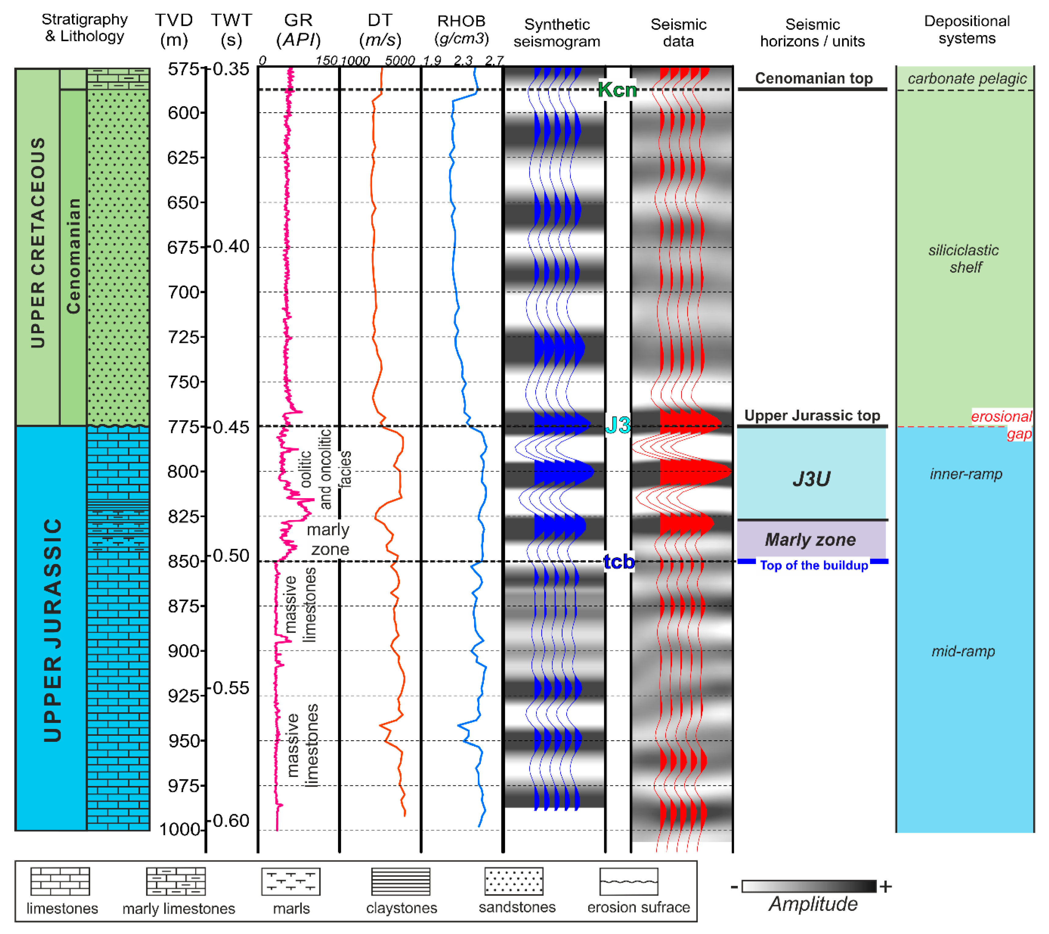
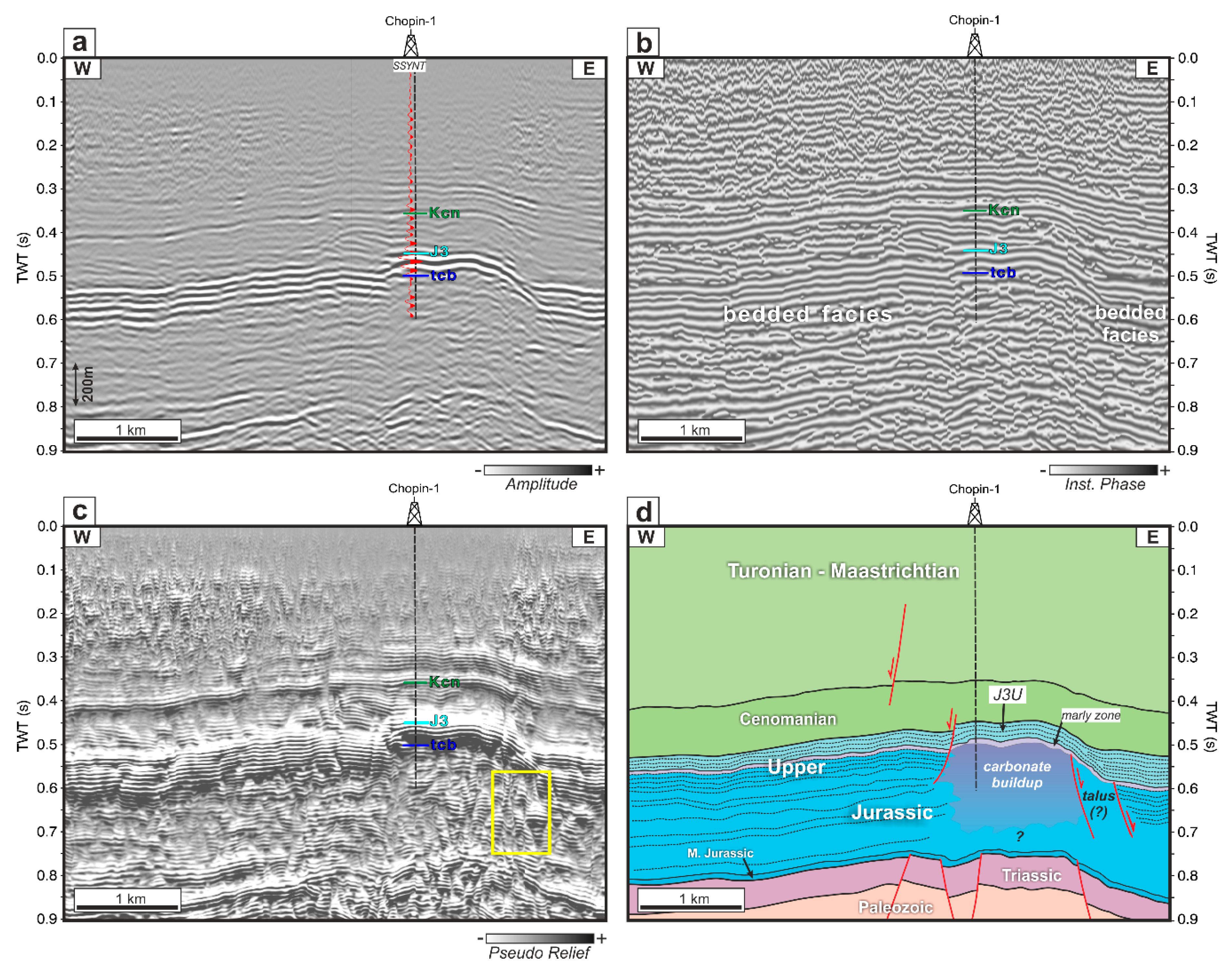
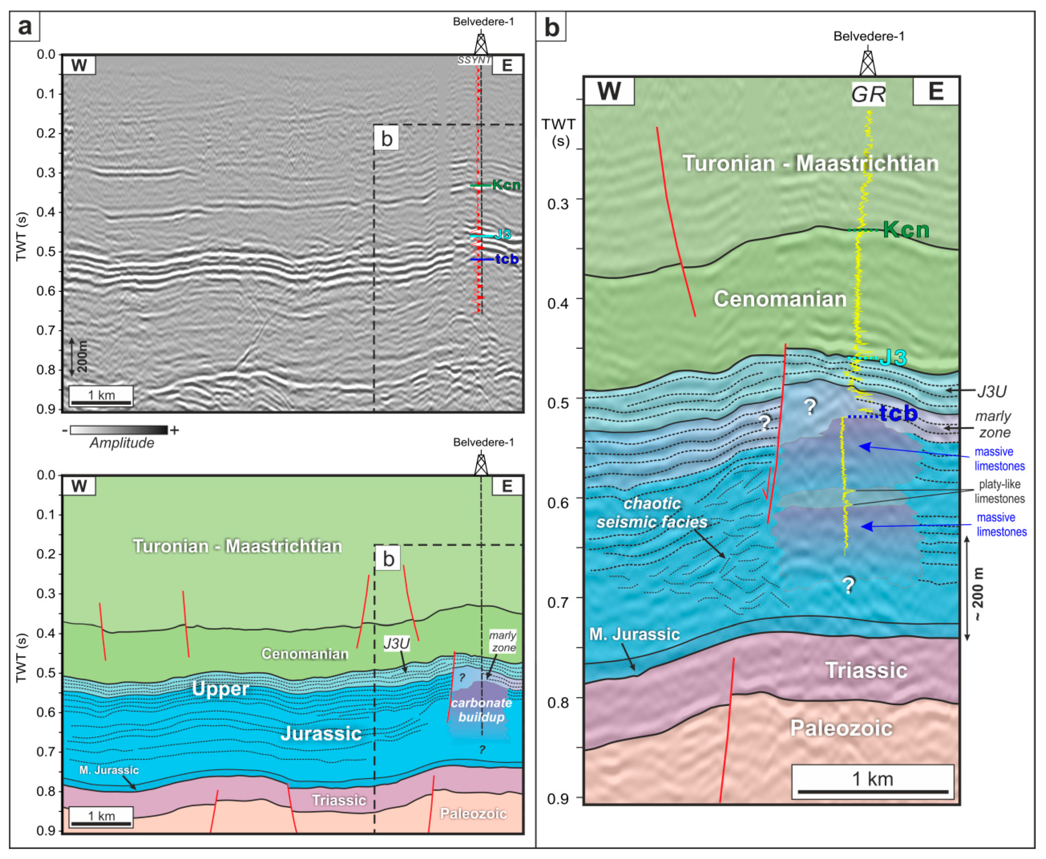
4.1. Well-to-Seismic Tie and Seismic-Stratigraphic Context

The correlation of well and seismic data was based on synthetic seismograms (Figure 3). Statistical wavelets extracted from seismic data have been used, with a dominant frequency of 30–35 Hz, and a signal length that varied between 120 and 150 ms. The two deepest wells, Węchadłów-1 and Lipówka-1, reached the top of the Paleozoic basement. The three other wells (Michałów-3, Węchadłów-1, Lipówka-1) were used for calibration of the top Triassic and top Middle Jurassic, while the top of the Upper Jurassic (J3) and top of Cenomanian (Kcn) were calibrated by all five wells. The best fit between synthetic seismograms and seismic data was obtained for SLE wells (Chopin-1 and Belvedere-1), due to the high quality of available sonic and density logs, which provided a precise time–depth relationship between the wells (in the depth domain) and seismic data (in the time domain). That was a critical step which allowed for the detailed correlation of stratigraphic boundaries and lithological profiles with seismic data. Moreover, extensive 1D seismic-stratigraphic analysis, which was carried out for the Chopin-1 and Belvedere-1 wells, enabled us to find a distinctive relationship between the Upper Jurassic lithology, facies and their seismic image (see [43] for further details).
The results of well-to-seismic data correlation obtained for the Chopin-1 well have been selected as a reference point for further seismic interpretation. This well drilled at its base was approximately 150 m of thick and homogenous hard limestone rocks, belonging to the carbonate buildup succession (Figure 3). The same succession, although more lithologically heterogeneous than in the Chopin-1 well, was drilled also in the Belvedere-1 well. These deposits are related to the massive limestones (massive facies) that commonly represent large microbial-sponge carbonate buildups or coral reefs (e.g., [17,19,27,69,124]). The top of the carbonate buildup complex in the Chopin-1 well was interpreted as the top of the massive limestones, which was seismically associated with low-amplitude and was a partly ambiguous reflector. This relatively poorly distinguishable seismic reflector is situated below the strongly interfered, high-amplitude, negative reflector, linked with the marly zone (Figure 3). On the other hand, the top of the massive limestones is very well visible on the natural gamma-ray log as a substantial contrast between high readings (associated with the above laying marly facies) and the much lower readings (related to the massive limestones). These low readings on the gamma-ray log are clearly observed for the entire massive limestone succession (Figure 3).
Above the massive limestones, a succession comprised of marls and marly limestones is present. Because of the increased content of clay minerals, this interval is clearly expressed by high readings on the natural gamma-ray log (Figure 3). The entire interval was termed the marly zone, and it is seismically expressed by high seismic amplitudes due to strong velocity contrasts between the uppermost oolitic succession and the marly facies below, as well as due to the presence of marls and marly limestone alternations. The top and the base of this interval were difficult to discern using only seismic data, due to the strong seismic tuning effects, and thus identification of the marly zone relied mainly on the well logs interpretation (natural gamma-ray log). Precise detection of the marly layers was hampered by intensive intra-bedded signal interference and seismic tuning, as well as the relatively low thickness of at least part of these marly units, which, in general, are at the limit of seismic data resolution (cf., [69,103]). Therefore, it was not possible to identify any of these layers using exclusively seismic data, although they are encompassed within the seismically identified marly zone (Figure 3). Generally, in the distinguished marly zone, the marly layers are interbedded by various limestone–marly strata. Similar marly–limestone layers or intercalations are present also within the lower part of the J3U interval (see below), and are related to high peaks on the gamma-ray log (Figure 3). Moreover, it should be emphasized here that, due to certain limitations of the seismic data described above (vertical resolution versus relatively thin marly beds), the upper part of the marly zone might extend into the lowermost part of the J3U interval, and both intervals, as such, can dovetail into each other in the analyzed seismic image (see Figure 3).
Above the marly zone, the J3U unit associated with differentiated deposits of the shallow-water carbonate platform [16,18,85], is present (Figure 3). This uppermost part of the Upper Jurassic succession in the study area comprises various oolitic and oncolitic facies, alternated by marly limestones and marls. Such alternations can be observed as high peaks on the natural gamma-ray log (Figure 3). However, due to relatively low thickness, in the order of 5–10 m, from those intercalations, it was not possible to identify them on seismic images without additional information from the well-log data, as many of these layers are generally below the vertical seismic data resolution. Therefore, the observed seismic image of the uppermost part of the Upper Jurassic succession (J3U seismic-stratigraphic interval, cf., [43]) is partly scattered by intra-bedded signal interferences (Figure 3). These interferences, caused by the strong overlap of reflective signals from the limestone strata and from the marly intercalations, have finally shaped the amplitude of all seismic horizons within the J3U interval, and this is the reason why this seismic-stratigraphic unit is expressed by a series of high-amplitude positive and negative seismic horizons (Figure 3).
The stratigraphic top of the Upper Jurassic was correlated with the well-pronounced high-amplitude positive reflector related to the erosional surface, above which the Cenomanian strata are deposited (Figure 3). As a result of the regional emergence of land and erosion in the Early Cretaceous, the youngest Upper Jurassic deposits were removed ([16,71]); the erosional gap includes also the entire Lower Cretaceous strata [117].
The relatively undifferentiated seismic image of the lowermost part of the Upper Cretaceous is related to the homogeneous lithology of siliciclastic Cenomanian deposits (see e.g., [139,140,141]). The low to medium amplitude response of this seismic interval might also be influenced by interference between signals reflected from the top and the base of thin sandstone beds. Such a tuning effect was described for Cenomanian deposits from the adjacent area located more in the south [142].

4.2. Interpretation of Seismic Data

4.2.1. Structural Interpretation of Seismic Data

The main seismic horizons defining the general structural grain of the broad study area, i.e., top Paleozoic, top Triassic, top Middle Jurassic, top Upper Jurassic and top Cenomanian, have been interpreted both on longer legacy profiles as well as on shorter SLE profiles. The J3U seismic-stratigraphic unit has also been interpreted using all these seismic profiles. Because of the lower quality and vertical resolution of the legacy seismic data, the marly zone has not been correlated in the legacy profiles.
The interpretation of the longer legacy seismic profiles revealed that the present-day structure of the study area was strongly influenced by the Late Cretaceous–Paleogene regional inversion of the Polish Basin (cf., [75,85,88]). Reverse faulting along the fault zones rooted in the Precambrian crystalline basement is clearly visible (Figure 4). The north-west– south-east oriented major fault zones are associated with inversion anticlines that developed within the Mesozoic cover. Considerable thickness variations, observed within the Upper Jurassic succession across these main faults, might suggest their syn-depositional activity in the Late Jurassic (cf. also [84,107]). Their most recent, main phase of activity was related to the Late Cretaceous–Paleogene inversion, which resulted in compressional–transpressional reactivation of the major basement faults. The inversion-related faulting and folding is visible within the entire Upper Cretaceous (Cenomanian–Maastrichtian) sedimentary cover, pointing to the latest Cretaceous–post-Cretaceous (Paleogene) age of the last phase of inversion tectonics in this part of the basin (Figure 4).
The pre-Mesozoic (Precambrian–Carboniferous) rocks of the Małopolska Block [73] are covered by the Triassic and Middle Jurassic deposits deposited within the southern outskirts of the Polish Basin. Within the entire Upper Jurassic succession in the study area, considerable lateral thickness changes are visible, which are related to variable Late Jurassic local subsidence patterns (Figure 4; cf., [107]) and later erosion (cf., [71]). The thickness of the Upper Jurassic interval is generally increasing towards the north-east (Figure 4), i.e., towards the Holy Cross Mountains, where the axial and most subsiding part of the Polish Basin was situated (Figure 1). The Jurassic–Cretaceous boundary is related to a subtle unconformity or disconformity that truncates the Upper Jurassic succession. The effect of the pre-Cenomanian erosion could be observed for the J3U seismic unit, whose uppermost seismic horizons form subtle truncation contacts towards the south-west (Figure 4). The Lower Cretaceous deposits are not present in the study area due to the regional emergence of land [117].

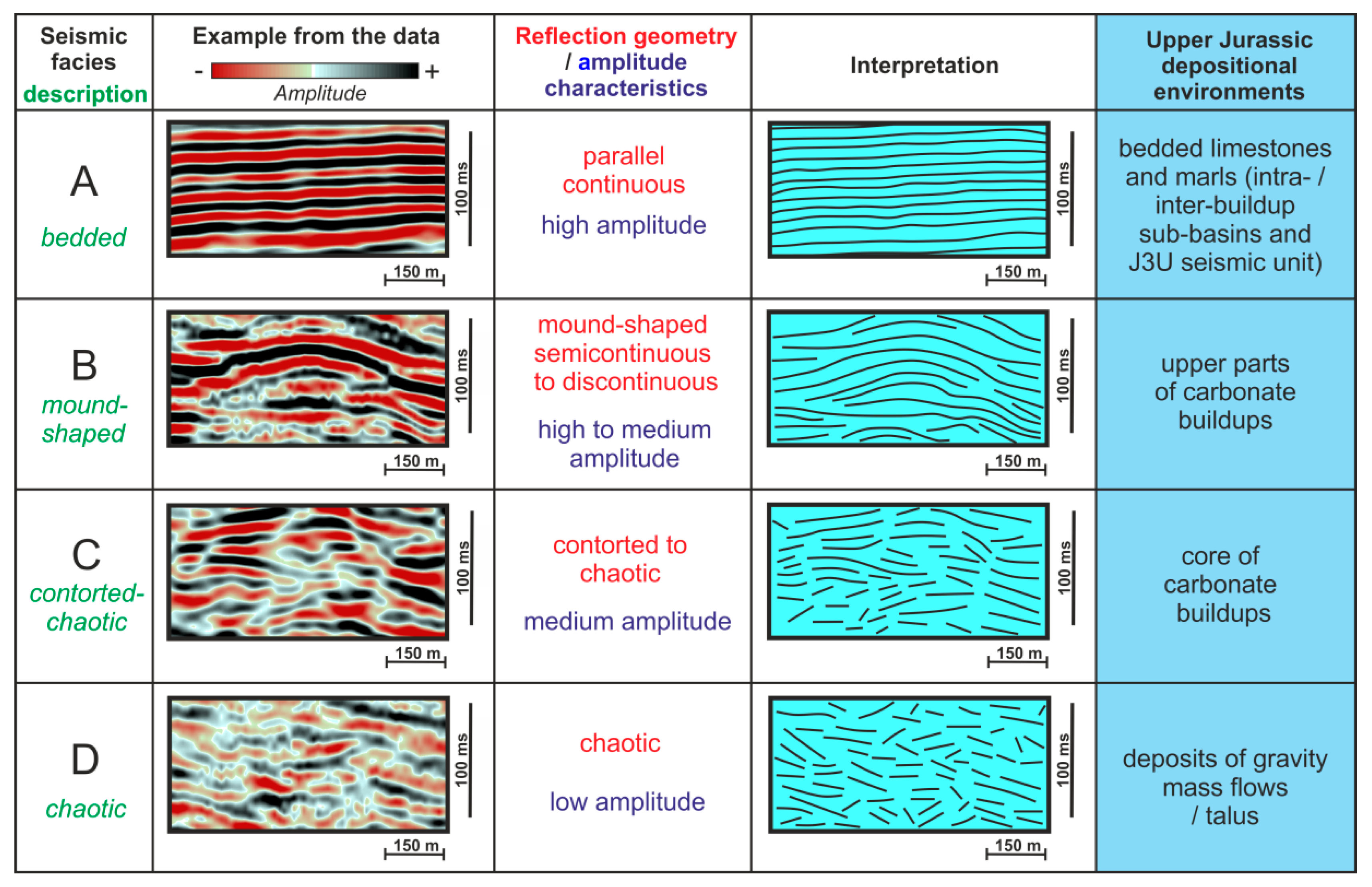
4.2.2. Seismic Facies Analysis

The seismic facies analysis was carried out for the entire Upper Jurassic interval in order to associate the main reflection patterns with the main depositional facies. The four main types of the seismic facies (A, B, C, D) have been distinguished (Figure 5). The proposed classification relies on reflection configuration, the continuity of seismic reflectors and amplitude characteristics.
Seismic facies type A is very common within the entire study area, and was termed the bedded seismic facies (Figure 5). This type is most pronounced within the upper parts of the Upper Jurassic interval. The reflection geometry of type A seismic facies is characterized by distinctive parallel and highly continuous seismic reflections. Analysis of reflection amplitude provides important information about velocity and density (acoustic impedance) contrasts at given geological boundaries [131]. Within the type A seismo-facies, the observed reflection amplitudes are rather high, which suggests significant lithological contrasts between well-stratified deposits. Such variability might be associated with the presence of high-impedance limestones intercalated by marly layers, that are characterized by much lower acoustic impedance. However, this reflection pattern was also modified by strong intra-bedded interference and the seismic tuning effect, caused by the seismic response from relatively thin marl–limestone alternations within the well-bedded succession (cf., [69]). The interpreted seismic facies A might be related to the bedded limestones and marls (forming the so-called bedded facies, see, e.g., [28]), typical for inter- or intra-buildup areas or sub-basins (see, e.g., [69]). These bedded seismic facies are also dominant for the entire J3U seismic unit that is overlying the carbonate buildups and intra-buildups basins, and could be associated with the well-bedded and lithologically diversified deposits of the shallow-water carbonate platform (cf., [18,71,105,106,112]).
The other seismic facies types (B, C and D) are less common. This suggests that the depositional facies they are associated with occur more locally. Seismic facies of type B represent mound-shaped reflection geometry, characterized by semi-continuous or partly discontinuous seismic reflections and high to medium reflection amplitude (Figure 5). Such a reflection configuration pattern has been well-described in the literature, and is often referred to as carbonate buildups (e.g., [29,39,44]). The interpreted seismic pattern is typical for upper parts of carbonate buildups (see Figure 5, Figure 6 and Figure 7).
Seismic facies type C represents contorted to chaotic reflection geometry and medium to strong reflection amplitude (Figure 5). It is predominantly observed within the cores of carbonate buildups (see Figure 6, Figure 7 and Figure 8). Lack of, or very low continuity of, seismic reflectors is related to the high-energy carbonate deposits forming reefal bodies (see e.g., [39]). Subsequent growth of the organic buildup is seismically expressed by the domination of diverse contorted and chaotic reflection patterns. The common occurrence of the type C seismic facies in the cores of the carbonate buildups could be related to their rigid framework, which is characteristic for the massive facies represented by microbial-sponge deposits (cf., [28,143]).
The type D seismic facies represents chaotic and low amplitude seismic reflections (Figure 5). This distinctive reflection pattern is observed close to the edges of large carbonate buildups (see Figure 7 and Figure 8). This seismic facies type could be linked with high-energy deposits surrounding organic buildup, that usually form talus, developed in front of a reef complex and containing mixed and reworked debris originating from the reef (e.g., [39]). The chaotic seismic facies identified in analyzed seismic profiles might be evidence of the mass-gravity transport off the buildups, which commonly occurred in the adjacent part of the basin at the turn of the Oxfordian and Kimmeridgian, and usually formed differentiated debris-flow deposits (e.g., [28,103,143]).

4.2.3. Seismic Attribute Analysis

The results of seismic attribute analysis for one of the legacy seismic profiles are shown in Figure 6. The analyzed part of this seismic profile embraces two carbonate buildups (Figure 6a). Local morphological highs beneath the Upper Jurassic interval suggest the presence of paleo-highs within the pre-Jurassic basement, that might have controlled the evolution of Upper Jurassic carbonate buildups (Figure 6a). It should be taken into account, however, that for seismic data in the time domain, analyzed pre-Jurassic basement geometry may be to some degree influenced by local velocity pull-up effects beneath the massive limestones that are characterized by higher seismic velocities than adjacent deposits (e.g., [29]; see [43] for more details).
The instantaneous amplitude (reflection strength) display, that is shown in Figure 6b, well underlines the main lithological contrast between the Upper Jurassic carbonate succession and the Cenomanian siliciclastic strata (cf., [22,40,42]). High values of the instantaneous amplitude also highlight the presence of the erosional top of the Upper Jurassic succession. The reflection strength shows highest values for the entire J3U seismic unit, i.e., within the uppermost part of the Upper Jurassic interval associated with oolitic and oncolitic facies, marly limestones and marls (Figure 6b,e). This is due to the significant vertical contrast between seismic velocities and densities between the Cenomanian siliciclastics and carbonates of the Upper Jurassic shallow-water carbonate platform succession (Figure 3 and Figure 6e; cf., [71,105,106]). Siliciclastic Cenomanian deposits are characterized by much lower seismic velocities than the seismically fast (about 5000 m/s) oolitic facies below. Such velocity changes resulted in high reflection coefficients at the Upper Jurassic–Cenomanian boundary. Such a significant contrast could be observed in the original (standard amplitude display) seismic data, as well as in the phase-independent (e.g., [137]), instantaneous amplitude display (cf. Figure 6a,b). Carbonate buildups represent low and medium reflection strength values, which generally coincide with their distinctive reflection pattern described by the seismic facies analysis (seismic facies type B–C; cf., Figure 5 and Figure 6b). The instantaneous phase attribute highlights the continuity of seismic reflections, and provides a better differentiation between the bedded seismic facies and carbonate buildups (Figure 6c). The bedded seismic facies exhibit very high continuity in the instantaneous phase display (Figure 6c,e). They are associated with the J3U unit, and inter- and intra-buildup sub-basins. On the other hand, the carbonate buildups revealed a distorted instantaneous phase image (Figure 6c,e). Such a distinctive attribute image coincides with the seismic facies identified for the carbonate buildups, characterized by semi-discontinuous or contorted/chaotic reflection patterns (Figure 5 and Figure 6c,e). The pseudo-relief attribute highlights the outline of the carbonate buildups (Figure 6d,e).
The results of seismic attribute analysis, carried out for the SLE seismic profile, are shown in Figure 7. This seismic profile shows the large carbonate buildup that was drilled by the Chopin-1 well. This structure was stratigraphically calibrated using well data via high-quality synthetic seismogram (Figure 7a). The seismic image of the core (interior) of this buildup represents type C contorted-chaotic seismic facies. The base of the structure is not clearly visible due to the lower quality of the seismic image (Figure 7a,e). The lateral extent of the bedded seismic facies surrounding the carbonate buildup on both its sides is much better highlighted by the instantaneous phase attribute (Figure 7b). Moreover, the distortion within the instantaneous phase display indicates the exact position of the carbonate buildup on this seismic profile (Figure 7b,d). The application of the pseudo-relief attribute revealed more reflections within the buildup’s interior, and much better emphasized its outline in comparison with the original amplitude seismic data (Figure 7a,c). Numerous discontinuous reflections within the core of the structure might evidence the high-energy sedimentary environment, favorable for the growth of the organic buildup (e.g., [39]). This carbonate buildup is bordered by the normal fault on its western side, and is also partly dissected by small-scale faults on its eastern side (Figure 7a,d). A more detailed image of this part of the seismic profile was provided by the pseudo-relief attribute, which also shows discontinuous reflections outside the reefal body continuing within its slope, and further into the east, towards the bedded facies (Figure 7c). This generally chaotic reflection pattern might be associated with the reefal talus, which is partly restricted by relatively small-scale normal faults (Figure 7c,d). Evidence of some local syn-depositional tectonic activity, revealed by the lateral thickness variations of the J3U, is also noticeable. The greater thickness of the JU3 interval is observed within the eastern part of this seismic profile, located above the inter-buildup sub-basin, and could be associated with the locally increased subsidence, and as a result, the increased accommodation space (Figure 7d). Such laterally variable syn-depositional subsidence might have been related to the activity of normal faults bordering the analyzed carbonate buildup, related to differential compaction (see below).

5. Discussion

5.1. Limitations and Potential Factors Influencing Seismic Expression of Carbonate Rocks

This paper provides the results of seismic interpretation, that allow for new insights into the subsurface Upper Jurassic carbonate buildups in the Miechów Trough. The conducted seismo-stratigraphic analysis required precise calibration between seismic and well data (lithological descriptions from cuttings and a set of modern geophysical logs). However, such an approach, based on seismic facies analysis, for the examination of buried carbonate rocks is considered a challenging task, due to the particular geologic characteristics of these sediments (cf., [44]). It should be remembered that most of the seismic reflections in sedimentary rocks have a composite character associated with contrasts in acoustic impedance. Important potential factors that might influence the acoustic impedance of carbonate rocks include changes in porosity and pore network structure, related to diagenetic history [144]. The diagenetic processes may considerably overprint the depositional architecture in carbonate settings, which, as a consequence, led to a distortion of the seismic imaging of carbonate strata and related seismo-stratigraphic interpretation of particular elements of the sedimentary environment [144]. In recent years, work by Burgess et al. [36] has been published that describes various limitations and potential factors influencing the seismic expression of carbonate buildups. Besides, numerous publications show one how to deal with potential limits in the seismo-stratigraphic interpretation of carbonate depositional systems, and to what extent modern seismic data can be used for the analysis of the evolution of ancient carbonate platforms, the examination of karst systems, or the impact of diagenesis (e.g., [49,52,144]). It has also been recommended that the investigation of the elements of the carbonate depositional system (including carbonate buildups), via the seismic facies approach, should be supported by adequate calibration between seismic data and sedimentological and diagenetic data obtained from well-cores [144]. Taking the above into account, an important restriction that this study had to deal with was a lack of core material. The conducted seismo-stratigraphic analysis was supported exclusively by lithological descriptions, based on cuttings, and by well log data.

5.2. Role of Differential Compaction

One of the important mechanisms that operated during and after deposition of the Upper Jurassic succession was differential compaction. Various aspects, concerning the compaction of carbonate rocks and its influence on different elements of the depositional architecture of the Upper Jurassic basin in southern Poland, have been described for the equivalent deposits that are outcroppings in the adjacent Kraków-Częstochowa Upland (e.g., [95,125,145,146]). In this well-recognized area, the Upper Jurassic succession consists of both carbonate buildup complexes and bedded detrital and pelitic limestone facies, present within the inter- and intra-buildup areas (e.g., [28,69,92,95,124]). Carbonate buildups and bedded facies reveal differential susceptibility to compaction [125]. Organic buildups with developed rigid frameworks were much more resistant to compaction in comparison with the well-stratified, compaction-prone bedded (basinal) limestone–marly deposits [95]. According to some authors, the differential compaction between the carbonate buildups and the bedded (basinal) facies was one of the factors that might have controlled the paleo-relief of the sea-bottom in the Late Jurassic basin [95,125].
Mechanical compaction had started already during deposition, and affected sediments until their lithification was completed (early diagenesis), whereas chemical compaction (pressure dissolution) commenced at the end of early diagenesis, and operated during late diagenesis ([125], see, e.g., [147,148] for details). According to Matyszkiewicz and Kochman [146], the pressure dissolution of the Upper Jurassic sediments ensued in two stages. The first stage operated at the end of the Late Jurassic, when the thickness of the overburden was sufficient to initiate this process [100,146]. The explicit break in compaction processes was related to the Early Cretaceous widespread regional erosion within the emerged land in southern Poland ([117,146]; cf., [149]). After this erosional stage, which reduced the overburden pressure (cf., [100,149]), the second stage of compaction commenced in the Late Cretaceous, once a sufficient thickness of sediments had accumulated to re-initiate pressure dissolution [146].
Several seismic evidences strongly support such a two-tier compaction scenario. Seismic horizons that are surrounding the carbonate buildup reveal characteristic compaction sags (Figure 8). Such a distinct seismic geometry indicates that rigid carbonate buildups were subjected to much lower compaction, in comparison to the compaction-prone, well-stratified basinal deposits formed between them (cf., [95,125]). As a result of the greater compaction of the bedded facies present within the inter-buildups areas, the characteristic draping of seismic horizons above the carbonate buildups (J3U seismic unit) can also be clearly observed (Figure 8).
Seismic data documented also the second, Late Cretaceous stage of compaction, that operated in the study area. Careful analysis of seismic data indicates that the Cenomanian succession generally imitates the morphology of the pre-Cenomanian paleo-surface, despite earlier formulated ideas that Cenomanian clastics gradually infilled post-Late Jurassic/post-Early Cretaceous paleo-morphology (cf., [139,140,142,150,151]). Seismic data shows that the Cenomanian succession, together with the lower part of the post-Cenomanian succession, drapes underlying Upper Jurassic paleo-morphology (see Figure 7 and Figure 8). Such geometry of the Upper Cretaceous seismic horizons could be at least partly related to the locally differentiated subsidence pattern, that might have been associated with the ensuing second stage of differential compaction of the Upper Jurassic sediments, in agreement with the model of Matyszkiewicz and Kochman [146]. Laterally variable compaction within the Upper Jurassic carbonate deposits has resulted in laterally variable subsidence during the early Late Cretaceous. This is documented by clearly divergent seismic packages within the Cenomanian succession, characterized by greater thicknesses above the intra-basinal finer-grained Upper Jurassic deposits, and lesser thicknesses above the rigid Upper Jurassic carbonate buildups (Figure 8). Draping above the Upper Jurassic carbonate buildups is visible in the lower part of the post-Cenomanian succession, and it progressively diminishes upward, suggesting the diminishing role of the compaction of the underlying Upper Jurassic carbonates, and probably also, to some degree, the lowermost Upper Cretaceous siliciclastics. Recently published seismic studies from other sedimentary basins have provided generally similar observations, regarding the effects of differential compaction associated with the carbonate buildup deposits of the Paleogene isolated carbonate platform from the Offshore Indus Basin ([50,51]. As shown by Shahzad et al. [51] (Figure 10 therein), characteristic draping effects above the buildup can be clearly observed within the younger overburden, caused by differential compaction.
Burgess et al. [36] stressed that differential compaction may also produce faults within the carbonate succession of laterally variable lithology. Adjacent to the large carbonate buildup complexes, several normal faults were identified within the Upper Jurassic interval; some of these faults also partly dissect the younger Cenomanian overburden (see Figure 7, Figure 8 and Figure 9). Seismic profiles clearly illustrate normal faults that developed at the interface between the rigid carbonate buildup and adjacent intra-basinal stratified infill. They also dissect the entire Cenomanian succession, and die out within the lowermost part of the post-Cenomanian interval. Their listric geometry and dissipation within the Upper Jurassic intra-basinal facies indicates their compactional origin (cf., [134]).

5.3. Development of Carbonate Buildups

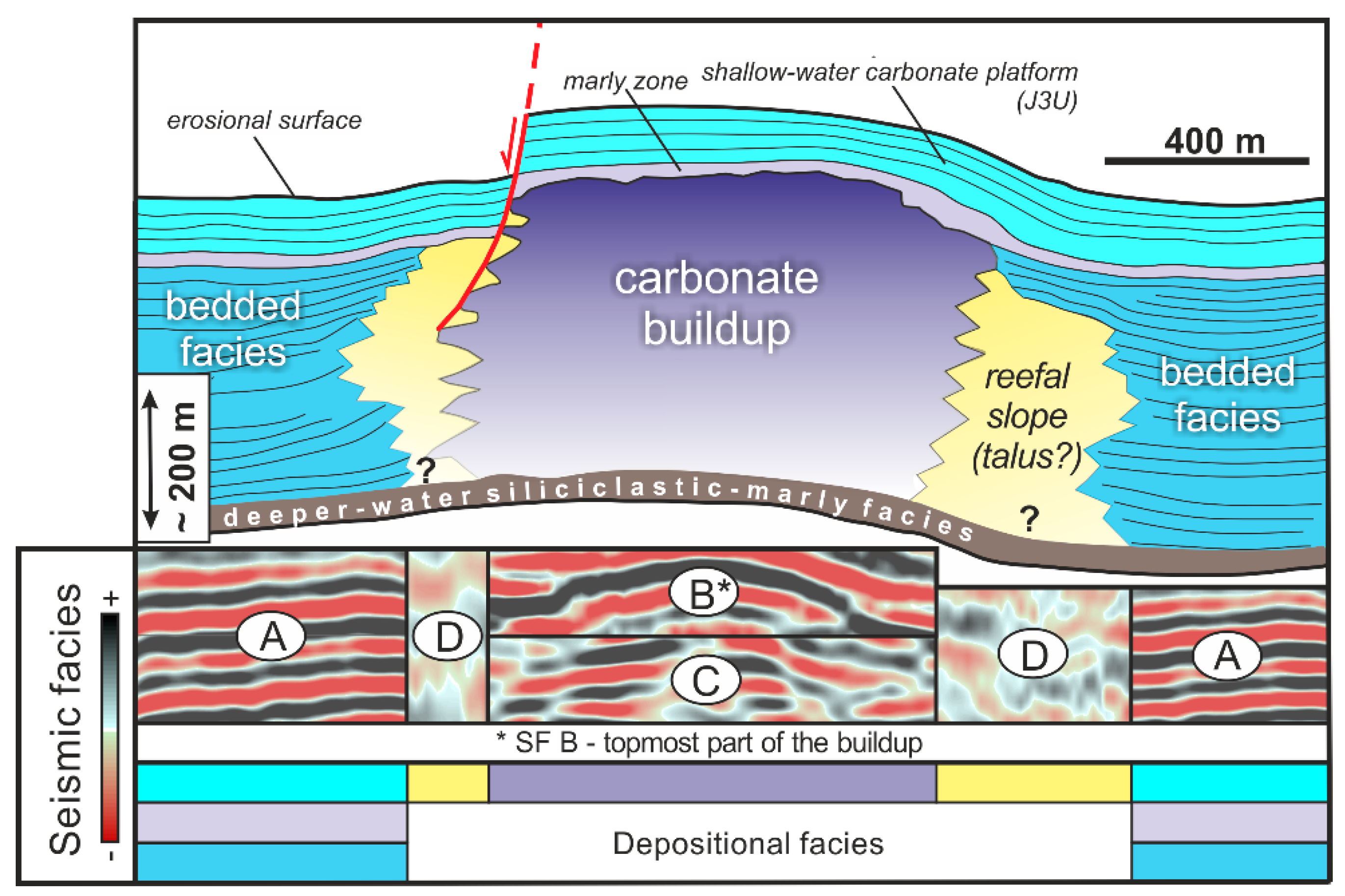
5.3.1. Internal Structure of the Carbonate Buildup Complex

The carbonate buildup, drilled by the Belvedere-1 well and shown in Figure 9a, represents a more heterogeneous complex, in comparison with the complex drilled by the Chopin-1 well (Figure 7). According to the data (natural gamma-ray log, lithological descriptions of the cuttings, etc.) from the Belvedere-1 well, the analyzed carbonate buildup is comprised of two massive limestone successions separated by a medium-hard, platy-like limestone interval (Figure 9b; cf., [121]). This may suggest the existence of the two main stages in reef development, which comprise the subsequent phases of growth that are related to consecutive levels of massive carbonate facies (cf., [19,70]). Similar observations were made recently by Urbaniec [22], using 3D seismic data from the southern part of the basin, presently located beneath the Miocene cover of the Carpathian Foredeep (see also [40,41,61,62,63,64]).

5.3.2. Deposits of the Gravity Mass-flows

The erosion of carbonate buildups might result in the formation of detrital limestones deposited on the slopes of the emerging structure (e.g., [28] and references therein). Deposits of mass-gravity transport were formed mostly as debris flows, but some finer-grained sediments were also described as calciturbidites [19,69,116,152].
Chaotic seismic facies (Figure 5) have been detected along the western side of the carbonate buildup, shown in Figure 9b. Chaotic seismic facies are located in close proximity of a normal fault, that developed due to differential compaction along the western edge of the carbonate buildup (Figure 9a,b). They were interpreted as a seismic image of deposits of the gravity mass-flows, comparable to similar deposits known of in the Upper Jurassic outcrops from this part of the basin (e.g., [28,69,103,143]).
A model of the formation of deposits of gravity mass-flows along the edges of the Upper Jurassic carbonate buildups, based on Matyszkiewicz [143] and supplemented by findings derived from seismic data interpretation, is shown in Figure 10 (cf., [17,19]). According to numerous authors, the formation of gravity mass-flows was related to the diversified paleo-relief of the Late Jurassic sea bottom, and synsedimentary activity along the main tectonic zones ([28,92,100,106,153]; Figure 10). Spatial coincidence of the identified chaotic seismic facies and normal faults that developed along the edges of the carbonate buildups suggests the important role of syn-depositional tectonic activity in the initiation of gravity mass-flow deposits. Considering that, as described above, the initiation of these normal faults might have been related to differential compaction, it can be postulated that such compaction might have been also one of the main mechanisms responsible for the formation of the deposits of gravity mass-flows encountered within the Upper Jurassic succession in this part of the basin.

5.3.3. Marly Zone

The combination and precise integration of the seismic and well-log data allowed for the identification of the specific seismic-stratigraphic interval termed the marly zone (Figure 3; cf., [43]), which has certain important stratigraphic associations in this part of the Late Jurassic basin (e.g., [19,69,100,103,106,113]). According to several authors, the appearance of these marly intercalations might have been climatically or tectonically triggered (e.g., [103,104,105]). Their presence reflects probably temporary breaks within the continuous limestone sedimentation in the early Kimmeridgian (e.g., [105,106]), as they could mark “deepening” events, whereby the carbonate platform was drowned and carbonate production ceased.
Seismically interpreted marly zone encompass several well-pronounced marly layers that are associated with high readings of the natural gamma-ray log (Figure 3 and Figure 9b). An example of the seismic interpretation of the marly zone drilled by the Chopin-1 well (cf. Figure 3) is shown in Figure 7.

5.3.4. Facies and Depositional Architecture

The integration of the results of seismic data interpretation with the rich supply of previously published literature served as a basis for the construction of a conceptual model of the Upper Jurassic succession in the study area (Figure 11). The identified key tectonic features, gross depositional geometries, and four categories of seismic facies have been associated with distinctive elements of the Upper Jurassic carbonate depositional system (Figure 11; cf. Figure 5).
The bedded seismic facies A is related to the mostly well-stratified deposits, including: (1) bedded facies that formed within the inter- and intra-buildup sub-basins (e.g., [4,69,103]), and (2) the marly zone and the JU3 interval of the shallow-water carbonate platform (e.g., [16,91,106,114]; cf., [43]; Figure 11). Within the equivalent Upper Jurassic deposits studied in the outcrops of the KCU (see Figure 1), the bedded facies comprise differentiated bedded limestones and marls (e.g., [28,69,92,121]). The interpretation of seismic data proved that in the study area, the bedded facies of the inter-bedded sub-basins pass upwards into the marly zone (Figure 11). The marly zone includes distinct marly layers that intercalate the carbonate succession above the carbonate buildups, and are related to the deeper-water sediments that documented drowning episodes that partly interrupted carbonate shelf sedimentation (Figure 7 and Figure 9; cf., [105,106]). The bedded seismic facies A dominates within the entire J3U seismic-stratigraphic interval associated with the inner ramp (i.e., shallow-water carbonate platform; Figure 11), which is represented by various oolitic, oncolitic and marly facies (e.g., [19,71,105,106,112,114]).
The mound-shaped seismic facies B and contorted-chaotic seismic facies C are related to the massive facies associated with carbonate buildup deposits (Figure 11). The massive facies are related, for example, to large complexes of microbial-sponge carbonate buildups, widely described in the outcrops of the KCU (Figure 1; e.g., [27,28] for further references). The seismic facies B and C, that represent carbonate buildups, pass laterally into the bedded seismic facies A associated with the bedded deposits of the inter-buildup sub-basins and areas, sometimes with intermediate intervals of sediments, representing talus, deposited on the reefal slope (Figure 5 and Figure 7). Outcrop studies from the KCU indicate that the contact between buildups and bedded (basinal) deposits is related the inclination of slopes, often ca. 30 degrees or steeper (e.g., [69,103]). The analyzed seismic image in general confirms similar geometries (Figure 8 and Figure 11). According to some previous studies (e.g., [95,124]), it is also possible that such observed geometries might partly result from differential compaction (cf., [125]).
The chaotic seismic facies D occurs only locally, and is generally representative of reefal talus within the slopes of carbonate buildup, which could also be related to various debris-flow deposits of the mass-gravity transport (e.g., [28,69]; Figure 11).
The interpretation of lateral seismic facies changes and their geometrical relations strongly suggest that the depositional architecture of the Upper Jurassic succession in the study area generally resembles that from the KCU (Figure 11; e.g., [4,28,69]; cf., [43]).

5.3.5. Comments on the Selected Factors Controlling the Initiation of Carbonate Buildups Development

So far, various opinions have been formulated regarding the initiation of growth of the carbonate buildups in southern Poland. According to Złonkiewicz [107], the Jurassic pattern of subsiding and elevating areas in the Miechów Trough might have been inherited from general tectonic patterns related to Variscan (late Paleozoic) tectonic movements. In the adjacent area of the KCU, the morphologically varied structure of the pre-Jurassic basement resulted from differential subsidence controlled by the presence of Paleozoic intrusions. Such intrusions determined the location of the morphological heights of the Jurassic sea-bottom. Such heights formed favorable areas for colonization by benthic fauna and the subsequent growth of carbonate buildups, whereas inter-buildup basins were subjected to increased subsidence that prevented the formation of carbonate buildups [27]. The Paleozoic intrusions, however, are not present in the substratum in the study area, as evidenced by magnetic maps of southern Poland (e.g., [154]), and therefore could not be invoked to explain the location of carbonate buildups. Several authors claimed that the Jurassic evolution of this part of the basin was controlled by syn-depositional basement normal and strike-slip faulting (e.g., [71,84,107,155]). According to Gutowski et al. [155], the paleogeographic distribution of the Late Jurassic carbonate depositional systems in the study area might have been related to the reactivation of the major basement strike-slip faults, such as the Zawiercie fault zone, deeply rooted in the Małpolska Block (e.g., [73]). Gutowski and Koyi [84] pointed out the role of this basement fault zone in controlling system of en echelon faults within the syn-tectonic sedimentary cover. According to Złonkiewicz [107,156], its interference with normal fault systems along the south-west border of the Mid-Polish Trough might have resulted in the formation of the pull-apart basin during the Late Jurassic (see also [71]). The north-east to south-east and west-to-east trending faulting might have shaped the paleogeography of the Miechów Trough during the Late Jurassic, and as such, might have influenced the distribution of carbonate buildups in the study area too (cf., [71]). It should, however, be stressed that all the above models linking Late Jurassic tectonics and depositional history were to a large degree speculative, based on various regional considerations or the results of analogue modelling, rather than data documenting the existence of postulated fault zones, etc. For example, regional Zawiercie [84] or Busko-Zawiercie [18] fault zone do not seem to have played important roles during the Late Jurassic tectono-sedimentary evolution of this area, as there is no important faulting along this zone documented by seismic data (cf., [43,75]).
The seismic profiles data shown in this paper do not provide any conclusive evidence regarding the significant role of regional fault zones in the formation of the Upper Jurassic carbonate buildups. Certain irregularities within the pre-Jurassic basement (substratum) have been identified; however, they seem to be rather local, of moderate displacement, and do not form any extensive zones crisscrossing this part of the basin (see also below). Taking this into account, it might be postulated that the initiation of the growth of carbonate buildups in the study area was primarily controlled by local pre-Jurassic tectonics, that formed small-scale morphological highs which were then used by various organisms, that eventually formed carbonate buildups.

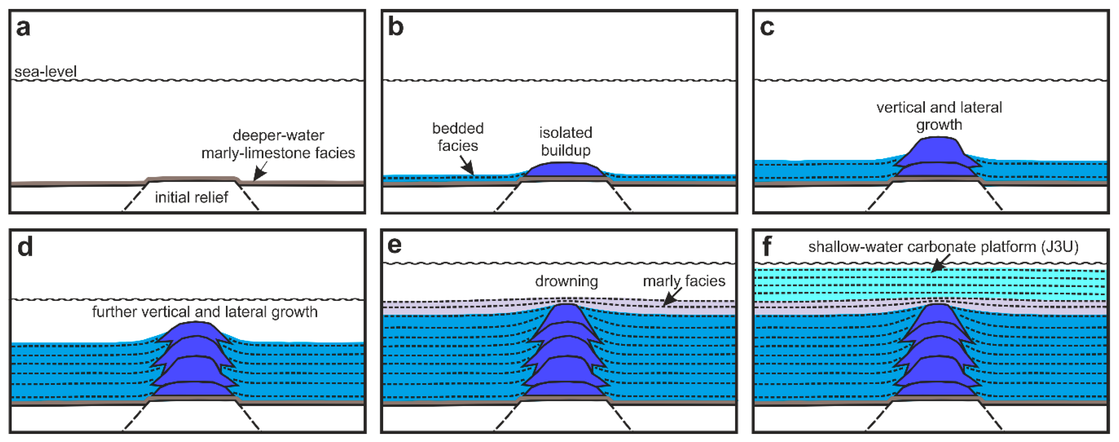
5.3.6. Development of Carbonate Buildups—Conceptual Model Based on Seismic Data

The results of the seismic interpretation presented in this paper, together with the rich supply of literature, were used to construct a generalized model of the development of the Upper Jurassic carbonate buildups and surrounding deposits (Figure 12). This schematic depositional model does not take into account the differential compaction of carbonate sediments that acted during the Late Jurassic deposition, and it does not include the local development of the gravity mass-flow deposits.
Similar models, that depict the gradual development of carbonate buildups and are based entirely on seismic data, are well known from the literature; for example, Shahzad et al. [50] proposed a detailed model of the growth and demise of the Paleogene isolated carbonate platform from the Offshore Indus Basin (Pakistan). For the model presented in this paper, a similar strategy was adopted.
Following the deeper-water marly–limestone sedimentation, that prevailed in the earliest Late Jurassic ([16,18,100,112,126]; Figure 12a), the widespread carbonate sedimentation started to dominate in the outer ramp conditions, generally characterized by the neritic water depths (e.g., [68,71,94]).
The existence of some sort of initial positive paleo-relief within the Late Jurassic sea-bottom was necessary for initiating the organic buildup’s growth (Figure 12a,b; see [6,27,28] and references therein). In the interpreted seismic data, some tectonically-controlled elevations beneath the carbonate buildups seem to be clearly visible (Figure 6, Figure 7 and Figure 8). Such pre-existing elevations on the Late Jurassic sea-bottom formed favorable sites for buildups in the study area. The elevated areas became settled by the microbialites and benthic fauna that initiated the growth of carbonate buildups [28], whereas in non-elevated areas the bedded facies have been deposited (Figure 12b; cf., [4,18,19,106,111,112]). These initially isolated structures might represent small-size sponge buildups, such as the “loose bioherms” [4,28,93] or siliceous–sponge–microbial mud mounds [157], but any speculations on that fall outside the scope of seismic data interpretation, due to obvious limitations in the resolution of seismic data.
Under favorable conditions for carbonate production (e.g., [15]), the organic buildups started intensive vertical (aggradational) growth (Figure 12c). They were characterized by a reticulate framework (cf., Figure 10; [28,143,158]), which is expressed in the analyzed seismic data by a discontinuous, contorted to chaotic seismic reflection pattern (Figure 5 and Figure 11), resulting from the high-energy reefal environment (cf., [39]). According to Matyszkiewicz et al. [28], the general trend of carbonate buildups growth that was observed in the adjacent area of KCU relied on the evolution of small sponge buildups into extensive sponge–microbial buildups, which became later replaced by microbial-sponge and microbial buildups, bearing a well-developed, rigid framework (cf., [4,27]). Finally, due to lateral (progradational) development, carbonate buildups formed large complexes [28]. The interpretation of seismic data revealed that further phases of carbonate buildup development in the study area include the two main stages of their vertical and lateral growth (Figure 12c,d). They could be linked to the presence of the two distinctly separated levels of massive limestones (cf., [19]), observed within the complex drilled by the Belvedere-1 well (Figure 9b). The intensity of the lateral development of the carbonate buildups was highlighted by the pseudo-relief seismic attribute (Figure 6d), and partly by the cosine-phase display (Figure 7b). The formation of seismically distinguishable lateral extends can be generally observed in the analyzed seismic data (compare Figure 6a,c,d, and Figure 7a–c). The surrounding bedded facies were subsequently deposited within the inter-buildup sub-basins (Figure 12b–d; cf., [69]).
Following further vertical and lateral growth, the carbonate buildups attained large sizes. According to outcrop studies in southern Poland, the tops of the large carbonate complexes were settled then by hermatypic corals (e.g., [19,69,103,106,159]; see also Figure 10). Deteriorating conditions controlling growth of the carbonate buildups coincided with the increased occurrence of the gravity mass-flows and synsedimentary tectonics (e.g., [28,100,106,160]; Figure 10). The appearance of various marly facies belonging to the seismically identified marly zone (Figure 12e; see also Figure 3 and Figure 9b) were related to temporary changes of the Late Jurassic sedimentation into deeper-water conditions, expressed by the presence of marly layers (cf., [17,19,100,103,116]). The marly layers could be related to drowning episodes and the demise of the carbonate buildups in the study area (cf., [106]).
The shallowing tendencies of the Late Jurassic depositional basin resulted in the development of the shallow-water carbonate sedimentation that started to prevail after the disappearance of the carbonate buildups (Figure 12f). These lithologically diversified deposits [106,112,114] are associated with the interpreted seismic-stratigraphic unit J3U (cf., [43]), and were formed in the study area within the shallow-water carbonate platform environment (i.e., inner ramp; cf., [19]; see also [69,91,114]).

5.4. Paleogeography of Carbonate Buildups in Southern Poland

The previously published Late Jurassic paleogeographic map of southern Poland and adjacent areas [161] presents the generalized locations of carbonate buildups that were almost directly linked with the present-day location of the Upper Jurassic deposits, in at least partly outcropped areas (Figure 13a). So far, the detailed recognition of carbonate buildups in southern Poland has mainly been related to the presence of the Upper Jurassic outcrops, e.g., in the Kraków-Częstochowa Upland and Wieluń Upland (Figure 13b; [21,69,103]). Furthermore, within the Upper Jurassic succession, southwards from the study area (in the extension of the Miechów Trough, that is situated beneath the Miocene Carpathian Foredeep Basin; cf., [120]), similar carbonate buildups were recognized using seismic data (Figure 13c; e.g., [40,59,60,61,62,63,65]). The results shown in this paper allow for the update of the Late Jurassic paleogeographic map of southern Poland, as this study provided a more detailed view of the previously less-recognized part of the Upper Jurassic basin in the Miechów Trough, where the system of the Upper Jurassic carbonate buildups surrounded by inter-buildup sub-basins was seismically investigated (Figure 13d). Taking this into account, it should be stressed that, in contrast to the map by Gaździcka [161], the distribution of Upper Jurassic buildups in southern Poland was much more extensive. This in turn proves that paleobathymetric and other conditions, necessary for the formation of such carbonate buildups, were not restricted to confined zones, but seem to have prevailed in large parts of the Late Jurassic basin.

6. Summary and Conclusions

The present study, dedicated to the Upper Jurassic carbonate buildups and surrounding deposits in the Miechów Trough, was based on advanced interpretation of the seismic data (seismic facies and seismic attribute analysis), supported by well data (borehole logs and lithological descriptions from cuttings). The Upper Jurassic carbonate depositional system in the study area, located within the transition zone that linked the epicontinental basin with the northern margin of the Tethys, has been less recognized before now, due to the deficiency of the outcrops and modern well data, in comparison with the other areas that were located on the northern Tethyan carbonate shelf in Poland and Europe. This study aimed to remedy this knowledge gap, and provide some insight regarding the structure and evolution of seismically imaged Upper Jurassic carbonate buildups and the surrounding deposits, including some specific aspects such as the initiation of their growth, the role of compaction or influence of syn-depositional tectonics, and the local depositional systems. It should be kept in mind that the provided ideas and solutions are, by definition, restricted by the resolution of seismic data, and should be subject to further studies and discussions.
Seismo-stratigraphic interpretation of the seismic data presented in this study allowed for the detailed recognition of the carbonate buildups and adjacent inter-buildup basins that were seismically recognized within the central Miechów Trough in southern Poland. Four main seismic facies types have been distinguished: (A) bedded, (B) mound-shaped, (C) contorted-chaotic, and (D) chaotic. They have been linked to main elements of the Late Jurassic depositional system: (1) bedded facies of the inter- and intra-buildup sub-basins, and the J3U seismic-stratigraphic unit, (2) massive facies (carbonate buildups), and (3) deposits of gravity mass-flows. Seismic analysis was supported by seismic attributes, that highlighted lateral seismic facies changes, and provided detailed information about the internal architecture of the Upper Jurassic basin infill and the outline of particular carbonate buildups.
The presented results were discussed and confronted with the current knowledge derived from numerous studies of adjacent outcropping areas of southern Poland, such as Kraków-Częstochowa Upland, Wieluń Upland the and southwestern rim of the Holy Cross Mountains. As a result, a depositional model for the Upper Jurassic succession in the Miechów Trough, that specifically focused on the carbonate buildups’ development, has been proposed. The proposed model of growth of the carbonate buildups represents consecutive phases of vertical and lateral development, which finally formed large reefal complexes, surrounded by the basinal facies. These deposits, following episodes of relative sea-level rise and associated drowning, were subsequently covered by bedded differentiated inner ramp facies, reflecting different stages of the shallow-water carbonate platform development. The shallow-water carbonate facies were assigned to the J3U seismic-stratigraphic interval. The marly zone occurring above the carbonate buildups reflect the episodes of carbonate shelf or ramp drowning, and the extinction of carbonate buildups.
This paper also emphasized the important role of two stages of compaction—the Late Jurassic, and then the Late Cretaceous. Conclusions based on seismic data regarding compaction processes conform very well with previously published studies based on outcrops.
The results of this study also show a more extensive distribution of the Upper Jurassic carbonate buildups in southern Poland than was previously suggested.

Author Contributions

Conceptualization, Ł.S., P.K.; investigation, Ł.S.; writing—original draft preparation, Ł.S.; writing—review and editing, Ł.S., P.K.; visualization, Ł.S.; supervision, P.K. All authors have read and agreed to the published version of the manuscript.

Funding

This research received no external funding.

Acknowledgments

The authors would like to thank San Leon Energy and PGNiG S.A for granting access to the seismic and well data used in this study. IHS Markit are thanked for providing Kingdom seismic interpretation software. CGG kindly provided Hampson-Russell software used for seismic attribute calculation and well-to-seismic correlations. Łukasz Słonka would like to thank Andrzej Wierzbowski, Jacek Matyszkiewicz, Jacek Gutowski and Andrzej Urbaniec for constructive comments on the early results of this study, and Aleksandra Stachowska for her help in collecting materials and helpful comments. Ashley Gumsley is thanked for correcting English. Anonymous reviewers are thanked for their detailed and insightful comments and suggestions, which greatly helped to finally refine this paper.

Conflicts of Interest

The authors declare no conflict of interest.

References

  1. Leinfelder, R.R. Upper Jurassic reef types and controlling factors. A preliminary report. Profil 1993, 5, 1–45. [Google Scholar]
  2. Leinfelder, R.R.; Krautter, M.; Laternser, R.; Nose, M.; Schmid, D.U.; Schweigert, G.; Werner, W.; Keupp, H.; Brugger, H.; Herrmann, R.; et al. The origin of Jurassic reefs: Current research developments and results. Facies 1994, 31, 1–56. [Google Scholar] [CrossRef]
  3. Leinfelder, R.R.; Schmid, D.U.; Nose, M.; Werner, W. Jurassic reef patterns—the expression of a changing globe. In Phanerozoic Reef Patterns; Kiessling, W., Flügel, E., Golonka, J., Eds.; Society for Sedimentary Geology: Tulsa, OK, USA, 2002; Volume 72, pp. 465–520. [Google Scholar] [CrossRef] [Green Version]
  4. Matyszkiewicz, J. Microfacies, sedimentation and some aspects of diagenesis of Upper Jurassic sediments from the elevated part of the Northern peri-Tethyan Shelf: A comparative study on the Lochen area (Schwäbische Alb) and the Cracow area (Cracow–Wielun Upland, Poland). Berl. Geowiss. Abh. 1997, 21, 1–111. [Google Scholar]
  5. Kiessling, W.; Flügel, E.; Golonka, J. Paleoreef Maps: Evaluation of a Comprehensive Database on Phanerozoic Reefs. AAPG Bull. 1999, 83, 1552–1587. [Google Scholar]
  6. Leinfelder, R.R.; Werner, W.; Nose, M.; Schmid, D.U.; Krautter, M.; Laternser, R.; Takacs, M.; Hartmann, D. Paleoecology, growth parameters and dynamics of coral, sponge and microbolite reefs from the Late Jurassic. Gött. Arb. Geol. Paläont. Sb. 1996, 2, 227–248. [Google Scholar]
  7. Guo, L.; Vincent, S.J.; Lavrishchev, V. Upper Jurassic Reefs from the Russian Western Caucasus: Implications for the Eastern Black Sea. Turk. J. Earth Sci. 2011, 20, 629–653. [Google Scholar] [CrossRef]
  8. Krajewski, M.; Schlagintweit, F. Crescentiella-microbial-cement microframeworks in the Upper Jurassic reefs of the Crimean Peninsula. Facies 2018, 64, 21:1–21:16. [Google Scholar] [CrossRef] [Green Version]
  9. Nikishin, A.M.; Okay, A.; Tüysüz, O.; Demirer, A.; Wannier, M.; Amelin, N.; Petrov, E. The Black Sea basins structure and history: New model based on new deep penetration regional seismic data. Part 1: Basins structure and fill. Mar. Petrol. Geol. 2015, 59, 638–655. [Google Scholar] [CrossRef]
  10. Nikishin, A.M.; Okay, A.; Tüysüz, O.; Demirer, A.; Wannier, M.; Amelin, N.; Petrov, E. The Black Sea basins structure and history: New model based on new deep penetration regional seismic data. Part 2: Tectonic history and paleogeography. Mar. Petrol. Geol. 2015, 59, 656–670. [Google Scholar] [CrossRef]
  11. Golonka, J. Plate tectonic evolution of the southern margin of Eurasia in the Mesozoic and Cenozoic. Tectonopysics 2004, 381, 235–273. [Google Scholar] [CrossRef]
  12. Cecca, F.; Martin Garin, B.; Lathhuiliere, B.; Bartolini, A. Paleoclimatic control of biogeographic and sedimentary events in Tethyan and peri-Tethyan areas during the Oxfordian (Late Jurassic). Palaeogeogr. Palaeoclimatol. Palaeoecol. 2005, 222, 10–32. [Google Scholar] [CrossRef] [Green Version]
  13. Rais, P.; Louis-Schmid, B.; Bernasconi, S.M.; Weissert, H. Palaeoceanographic and palaeoclimatic reorganization around the Middle–Late Jurassic transition. Palaeogeogr. Palaeoclimatol. Palaeoecol. 2007, 251, 527–546. [Google Scholar] [CrossRef]
  14. Wierzbowski, H.; Anczkiewicz, R.; Pawlak, J.; Rogov, M.A.; Kuznetsov, A.B. Revised Middle–Upper Jurassic strontium isotope stratigraphy. Chem. Geol. 2017, 466, 239–255. [Google Scholar] [CrossRef]
  15. Kendall, C.G.S.C.; Schlager, W. Carbonates and relative changes in sea level. Mar. Geol. 1981, 44, 181–212. [Google Scholar] [CrossRef]
  16. Gutowski, J.; Popadyuk, I.V.; Olszewska, B. Late Jurassic-earliest Cretaceous evolution of the epicontinental sedimentary basin of southeastern Poland and Western Ukraine. Geol. Q. 2005, 49, 31–44. [Google Scholar] [CrossRef]
  17. Krajewski, M.; Olchowy, P.; Felisiak, I. Late Jurassic facies architecture of the Złoczew Graben: Implications for evolution of the tectonic-controlled northern peri-Tethyan shelf (Upper Oxfordian–Lower Kimmeridgian, Poland). Facies 2016, 62, 4:1–4:19. [Google Scholar] [CrossRef] [Green Version]
  18. Matyja, B.A. Development of the Mid-Polish Trough versus Late Jurassic evolution in the Carpathian Foredeep area. Geol. Q. 2009, 51, 49–62. [Google Scholar]
  19. Olchowy, P.; Krajewski, M.; Felisiak, I. Late Jurassic facies succession of the Kleszczów Graben area (southern border of the Łódź Depression, peri-Tethyan shelf, central Poland). Geol. Q. 2019, 63, 657–681. [Google Scholar] [CrossRef] [Green Version]
  20. Krajewski, M.; Matyszkiewicz, J.; Król, K.; Olszewska, B. Facies of the Upper Jurassic–Lower Cretaceous deposits from the southern part of the Carpathian Foredeep basement in the Kraków–Rzeszów area (southern Poland). Ann. Soc. Geol. Pol. 2011, 81, 269–290. [Google Scholar]
  21. Olszewska, B.; Matyszkiewicz, J.; Król, K.; Krajewski, M. Correlation of the Upper Jurassic-Cretaceous epicontinental sediments in southern Poland and south western Ukraine based on thin section. Biul. Państw. Inst. Geol. 2012, 453, 29–80. [Google Scholar]
  22. Urbaniec, A. Lithofacial development of the Upper Jurassic and Lower Cretaceous Deposits in the Dąbrowa Tarnowska-Dębica Area Based on the 3D Seismic Interpretation. Ph.D. Thesis, AGH University of Science and Technology, Kraków, Poland, November 2018. (In Polish). [Google Scholar]
  23. Burne, R.V.; Moore, L.S. Microbialites: Organosedimentary Deposits of Benthic Microbial Communities. Palaois 1987, 2, 241–254. [Google Scholar] [CrossRef]
  24. Riding, R. Microbial carbonates: The geological record of calcified bacterial–algal mats and biofilms. Sedimentology 2000, 47, 179–214. [Google Scholar] [CrossRef]
  25. Riding, R. Structure and composition of organic reefs and carbonate mud mounds: Concepts and categories. Earth-Sci. Rev. 2002, 58, 163–231. [Google Scholar] [CrossRef]
  26. Gwinner, M.P. Carbonate rocks of the Upper Jurassic in SW-Germany. In Sedimentology of Parts of Central Europe; Müller, G., Ed.; Kramer: Frankfurt, Germany, 1971; pp. 193–207. [Google Scholar]
  27. Matyszkiewicz, J.; Krajewski, M.; Kędzierski, J. Origin and evolution of an Upper Jurassic complex of carbonate buildups from Zegarowe Rocks (Kraków–Wieluń Upland, Poland). Facies 2006, 52, 249–263. [Google Scholar] [CrossRef]
  28. Matyszkiewicz, J.; Kochman, A.; Duś, A. Influence of local sedimentary conditions on development of microbialites in the Oxfordian carbonate buildups from the southern part of the Kraków-Częstochowa Upland (south Poland). Sediment. Geol. 2012, 263–264, 109–132. [Google Scholar] [CrossRef]
  29. Bubb, J.N.; Hatlelid, W.G. Seismic stratigraphy and global changes of sea level, Part 10: Seismic recognition of carbonate buildups. In Seismic Stratigraphy—Applications to Hydrocarbon Exploration; Payton, C.E., Ed.; American Association of Petroleum Geologists: Tulsa, OK, USA, 1977; Volume 26, pp. 185–204. [Google Scholar] [CrossRef]
  30. Blendinger, W.; Bowlin, B.; Zijp, F.R.; Darke, G.; Ekroll, M. Carbonate buildup flank deposits: An example from the Permian (Barents Sea, northern Norway) challenges classical facies models. Sediment. Geol. 1997, 112, 89–103. [Google Scholar] [CrossRef]
  31. Elvebakk, G.; Hunt, D.W.; Stemmerik, L. From isolated buildups to buildup mosaics: 3D seismic sheds new light on upper Carboniferous–Permian fault controlled carbonate buildups, Norwegian Barents Sea. Sediment. Geol. 2002, 152, 7–17. [Google Scholar] [CrossRef]
  32. Belopolsky, A.V.; Droxler, A.W. Seismic Expressions and Interpretation of Carbonate Sequences: The Maldives Platform, Equatorial Indian Ocean. AAPG Stud. Geol. 2004, 49, 49:1–49:66. [Google Scholar] [CrossRef]
  33. Zampetti, V.; Schlager, W.; van Konijnenburg, J.H.; Everts, A.J. Architecture and growth history of a Miocene carbonate platform from 3D seismic reflection data; Luconia Province, offshore Sarawak, Malaysia. Mar. Petrol. Geol. 2004, 21, 517–534. [Google Scholar] [CrossRef]
  34. Fournier, F.; Borgomano, J. Geological significance of seismic reflections and imaging of the reservoir architecture in the Malampaya gas field (Philippines). AAPG Bull. 2007, 91, 235–258. [Google Scholar] [CrossRef]
  35. Rafaelsen, B.; Elvebakk, G.; Andreassen, K.; Stemmerik, L.; Colpaert, A.; Samuelsberg, T.J. From detached to attached carbonate buildup complexes—3D seismic data from the upper Palaeozoic, Finnmark Platform, southwestern Barents Sea. Sediment. Geol. 2008, 206, 17–32. [Google Scholar] [CrossRef]
  36. Burgess, P.M.; Winefield, P.; Minzoni, M.; Elders, C. Methods for identification of isolated carbonate buildups from seismic reflection data. AAPG Bull. 2013, 97, 1071–1098. [Google Scholar] [CrossRef]
  37. Saqab, M.M.; Bourget, J. Seismic geomorphology and evolution of early mid Miocene isolated carbonate build-ups in the Timor Sea, North West Shelf of Australia. Mar. Geol. 2016, 369, 224–245. [Google Scholar] [CrossRef]
  38. Philips, T.; Jackson, C.A.L.; Bell, R.; Valencia, A. Rivers, reefs, and deltas; Geomorphological evolution of the Jurassic of the Farsund Basin, offshore southern Norway. Petrol. Geosci. 2019, 26, 81–100. [Google Scholar] [CrossRef]
  39. Veeken, P.; van Moerkerken, B. Seismic Stratigraphy and Depositional Facies Models; EAGE Publications: Houten, The Netherlands, 2013; ISBN 978-0124114555. [Google Scholar]
  40. Gliniak, P.; Gutowski, J.; Urbaniec, A. Organic buildups recog nized upon well and seismic data within the Upper Jurassic formations of the Carpathian foreland, Poland; perspectives for hydrocarbon exploration. Vol. Jurass. 2005, 3, 29–43, (In Polish, with English summary). [Google Scholar]
  41. Jędrzejowska-Tyczkowska, H.; Misiarz, P.; Golonka, J.; Przejczowska, A. Outrop information and seismic analogs in analysis of Jurassic buildups (Poland). In Proceedings of the 67th EAGE Conference & Exhibition, Madrid, Spain, 13–16 June 2005; European Association of Geoscientists & Engineers: Houten, The Netherlands, 2005. [Google Scholar] [CrossRef]
  42. Jędrzejowska-Tyczkowska, H.; Golonka, J.; Misiarz, P.; Krobicki, M.; Matyszkiewicz, J.; Olszewska, B.; Przejczowska, A.; Oszczypko, N. Upper Jurassic carbonate buildups in the Carpathian foreland in Poland: Geological and geophysical setting. Vol. Jurass. 2006, 4, 92–93. [Google Scholar]
  43. Słonka, Ł.; Krzywiec, P. Upper Jurassic carbonate buildups in the Miechów Trough, Southern Poland – insights from seismic data interpretation. Solid Earth Discuss. 2019. [Google Scholar] [CrossRef] [Green Version]
  44. Fontaine, J.M.; Cussey, R.; Lacaze, J.; Lanaud, R.; Yapaudjian, L. Seismic interpretation of carbonate depositional environments. AAPG Bull. 1987, 71, 281–297. [Google Scholar] [CrossRef]
  45. Posamentier, H.W.; Laurin, P.; Warmath, A.; Purnama, M.; Drajat, D. Seismic stratigraphy and geomorphology of Oligocene to Miocene carbonate buildups offshore Madura, Indonesia. In Cenozoic Carbonate Systems of Australasia; Morgan, W.A., George, A.D., Harris, P.M., Kupecz, J.A., Sarg, J.F., Eds.; SEPM Society for Sedimentary Geology: Tulsa, OK, USA, 2010; Volume 95, pp. 175–194. [Google Scholar] [CrossRef]
  46. Rosleff-Soerensen, B.; Reuning, L.; Back, S.; Kukla, P. Seismic geomorphology and growth architecture of a Miocene barrier reef, Browse Basin, NW-Australia. Mar. Petrol. Geol. 2012, 29, 233–254. [Google Scholar] [CrossRef] [Green Version]
  47. Koša, E. Sea-level changes, shoreline journeys, and the seismic stratigraphy of Central Luconia, Miocene-present, offshore Sarawak, NW Borneo. Mar. Petrol. Geol. 2015, 59, 35–55. [Google Scholar] [CrossRef]
  48. Di Lucia, M.; Sayago, J.; Frijia, G.; Cotti, A.; Sitta, A.; Mutti, M. Facies and seismic analysis of the Late Carboniferous – Early Permian Finnmark carbonate platform (southern Norwegian Barents Sea): An assessment of the carbonate factories and depositional geometries. Mar. Petrol. Geol. 2017, 79, 372–393. [Google Scholar] [CrossRef]
  49. Paumard, V.; Zuckmeyer, E.; Boichard, R.; Jorry, S.J.; Bourget, J.; Borgomano, J.; Maurin, T.; Ferry, J.N. Evolution of Late Oligocene – Early Miocene attached and isolated carbonate platforms in a volcanic ridge context (Maldives type), Yadana field, offshore Myanmar. Mar. Petrol. Geol. 2017, 81, 361–387. [Google Scholar] [CrossRef] [Green Version]
  50. Shahzad, K.; Betzler, C.; Ahmed, N.; Qayyum, F.; Spezzaferri, S.; Qadir, A. Growth and demise of a Paleogene isolated carbonate platform of the Offshore Indus Basin, Pakistan: Effects of regional and local controlling factors. Int. J. Earth Sci. 2018, 107, 481–504. [Google Scholar] [CrossRef]
  51. Shahzad, K.; Betzler, C.; Qayyum, F. Controls on the Paleogene carbonate platform growth under greenhouse climate conditions (Offshore Indus Basin). Mar. Petrol. Geol. 2019, 101, 519–539. [Google Scholar] [CrossRef]
  52. Van Tuyl, J.; Alves, T.M.; Cherns, L. Geometric and depositional responses of carbonate build-ups to Miocene sea level and regional tectonics offshore northwest Australia. Mar. Petrol. Geol. 2018, 94, 144–165. [Google Scholar] [CrossRef]
  53. Van Tuyl, J.; Alves, T.; Cherns, L.; Antonatos, G.; Burgess, P.; Masiero, I. Geomorphological evidence of carbonate build-up demise on equatorial margins: A case study from offshore northwest Australia. Mar. Petrol. Geol. 2019, 104, 125–149. [Google Scholar] [CrossRef]
  54. Zimmer, W.; Wessely, G. Exploration results in thrust- and subthrust complexes in the Alps and below the Vienna Basin in Austria. In Oil and gas in Alpidic Thrustbelts and Basins of Central and Eastern Europe; Wessely, G., Liebl, W., Eds.; Geological Society: London, UK, 1996; Volume 5, pp. 81–107. [Google Scholar] [CrossRef]
  55. Adámek, J. The Jurassic floor of the Bohemian Massif in Moravia–geology and paleogeography. Bull. Geosci. 2005, 80, 91–305. [Google Scholar] [CrossRef]
  56. Hartmann, H.; Buness, H.; Krawczyk, C.M.; Schulz, R. 3-D seismic analysis of a carbonate platform in the Molasse Basin - reef distribution and internal separation with seismic attributes. Tectonophysics 2012, 572, 16–25. [Google Scholar] [CrossRef]
  57. Lüschen, E.; Wolfgramm, M.; Fritzer, T.; Dussel, M.; Thomas, R.; Schulz, R. 3D seismic survey explores geothermal targets for reservoir characterization at Unterhaching, Munich, Germany. Geothermics 2014, 50, 167–179. [Google Scholar] [CrossRef]
  58. Gliniak, P.; Laskowicz, R.; Urbaniec, A. Upper Jurassic organic constructions in Bochnia–Dębica area—possibility of recognition on seismic section and exploration prospections of hydrocarbon reservoirs. Inst. Oil Gas–Krak. Spec. Pap. 2000, 110, 161–165, (In Polish, with English summary). [Google Scholar]
  59. Gliniak, P.; Laskowicz, A.; Urbaniec, A.; Such, P.; Leśniak, G. Reservoir rocks and facies development of the Upper Jurassic carbonate in Zawada—Lękawica area. Nafta-Gaz Press 2001, 11, 597–606, (In Polish, with English summary). [Google Scholar]
  60. Gliniak, P.; Laskowicz, R.; Urbaniec, A.; Leśniak, G.; Such, P. The facies development and reservoir properties in Late Jurassic carbonate sediments in the central Carpathian foreland. In Deformation, Fluid Flow and Reservoir Appraisal in Foreland Fold; Swennen, R., Roure, F., Granath, J.W., Eds.; American Association of Petroleum Geologists: Tulsa, OK, USA, 2004; pp. 347–355. [Google Scholar] [CrossRef]
  61. Gliniak, P.; Urbaniec, A. Oxford biohermal structures in the area Bochnia-Sędziszów in seismic 3D recording. Nafta-Gaz Press 2001, 10, 545–556, (In Polish, with English summary). [Google Scholar]
  62. Gliniak, P.; Urbaniec, A. Geophysical characteristic of Oxfordian bioherms in the Carpathian foreland area in the aspect of new techniques of hydrocarbons searching. Nafta-Gaz Press 2005, 61, 343–348, (In Polish, with English summary). [Google Scholar]
  63. Misiarz, P. Coherence analysis of 3D seismic record for detection and characterisation of biohermal objects and structural discontinuities in the Carpathian Foreland. Nafta-Gaz Press 2003, 59, 70–79, (In Polish with English summary). [Google Scholar]
  64. Misiarz, P.; Jędrzejowska-Tyczkowska, H.; Oszczypko, N.; Golonka, J.; Olszewska, B.; Matyszkiewicz, J. Oxfordian bioherms from the central part of the Carpathian foreland (Poland)—seismic modeling results. In Proceedings of the AAPG European Regional Conference with GSA, Prague, Czech Republic, 10–13 October 2004; American Association of Petroleum Geologists: Tulsa, OK, USA, 2004; p. 94. [Google Scholar]
  65. Myśliwiec, M.; Borys, Z.; Bosak, B.; Liszka, B.; Madej, K.; Maksym, A.; Oleszkiewicz, K.; Pietrusiak, M.; Plezia, B.; Staryszak, G.; et al. Hydrocarbon resources of the Polish Carpathian Foredeep: Reservoirs, traps, and selected hydrocarbon fields. In The Carpathians and Their Foreland: Geology and Hydrocarbon Resources; Golonka, J., Picha, F.J., Eds.; American Association of Petroleum Geologists: Tulsa, OK, USA, 2006; Volume 84, pp. 351–393. [Google Scholar] [CrossRef]
  66. Dadlez, R.; Marek, S.; Pokorski, J. Geological Map of Poland without Cainozoic Deposits (1:1,000,000); Polish Geological Institute: Warszawa, Poland, 2000. [Google Scholar]
  67. Żytko, K.; Gucik, S.; Ryłko, W.; Oszczypko, N.; Zając, R.; Garlicka, I.; Nemčok, J.; Elias, M.; Mencik, E.; Dvorak, J.; et al. Geological map of the Western Outer Carpathians and their foreland without Quaternary formations (1:500,000). In Geological Atlas of the Western Outer Carpathians and their Foreland; Poprawa, D., Nemčok, J., Eds.; Polish Geological Institute: Warszawa, Poland, 1988. [Google Scholar]
  68. Matyja, B.A.; Wierzbowski, A. Sea bottom relief and bathymetry of Late Jurassic sponge megafacies in Poland. Geores. Forum 1996, 1–2, 333–340. [Google Scholar]
  69. Matyja, B.A.; Wierzbowski, A. Open shelf facies of the Polish Jura Chain. In Jurassic of Poland and Adjacent Slovakian Carpathians: Field Trip Guidebook of the 7th International Congress on the Jurassic System, Poland, Kraków, September 6–18, 2006; Wierzbowski, A., Aubrecht, R., Golonka, J., Gutowski, J., Krobicki, M., Matyja, B.A., Pieńkowski, G., Uchman, A., Eds.; Polish Geological Institute: Warszawa, Poland, 2006; pp. 198–206. [Google Scholar]
  70. Krajewski, M.; Olchowy, P.; Rudziński, D. Sedimentary successions in the Middle–Upper Oxfordian reef deposits from the southern part of the Kraków–Częstochowa Upland (Southern Poland). Geol. Q. 2018, 62, 653–668. [Google Scholar] [CrossRef] [Green Version]
  71. Gutowski, J. Field trip B2—Upper Jurassic shallow-water carbonate platform and open shelf facies. Introduction. In Jurassic of Poland and Adjacent Slovakian Carpathians: Field Trip Guidebook of the 7th International Congress on the Jurassic System, Poland, Kraków, September 6–18, 2006; Wierzbowski, A., Aubrecht, R., Golonka, J., Gutowski, J., Krobicki, M., Matyja, B.A., Pieńkowski, G., Uchman, A., Eds.; Polish Geological Institute: Warszawa, Poland, 2006; pp. 169–173. [Google Scholar]
  72. Kowal-Kasprzyk, J.; Krajewski, M.; Gedl, P. The oldest stage of the Outer Carpathian evolution in the light of Oxfordian–Kimmeridgian exotic clast studies (southern Poland). Facies 2020, 66, 11:1–11:23. [Google Scholar] [CrossRef] [Green Version]
  73. Żelaźniewicz, A.; Aleksandrowski, P.; Buła, Z.; Karnkowski, P.; Konon, A.; Oszczypko, N.; Ślączka, A.; Żaba, J.; Żytko, K. Tectonic Subdivision of Poland; Komitet Nauk Geologicznych PAN: Wrocław, Poland, 2011. (In Polish) [Google Scholar]
  74. Ziegler, P.A. Geological Atlas of Western and Central Europe, 2nd ed.; Shell International Petroleum Maatschappij B.V. and Geological Society: London, UK, 1990. [Google Scholar]
  75. Scheck-Wenderoth, M.; Krzywiec, P.; Zülke, R.; Maystrenko, Y.; Frizheim, N. Permian to Cretaceous tectonics. In The Geology of Central Europe; McCann, T., Ed.; Geological Society: London, UK, 2008; pp. 999–1030. [Google Scholar] [CrossRef]
  76. Pharaoh, T.; Dusar, M.; Geluk, M.; Kockel, F.; Krawczyk, C.; Krzywiec, P.; Scheck-Wenderoth, M.; Thybo, H.; Vejbæk, O.; van Wees, J.D. Tectonic evolution. In Petroleum Geological Atlas of the Southern Permian Basin Area; Doornenbal, J.C., Stevenson, A.G., Eds.; EAGE Publications: Houten, The Netherlands, 2010; pp. 25–57. [Google Scholar]
  77. Mazur, S.; Mikołajczak, M.; Krzywiec, P.; Malinowski, M.; Buffenmyer, V.; Lewandowski, M. Is the Teisseyre-Tornquist Zone an ancient plate boundary of Baltica? Tectonics 2015, 34, 2465–2477. [Google Scholar] [CrossRef] [Green Version]
  78. Kutek, J.; Głazek, J. The Holy Cross Area, Central Poland, in the Alpine Cycle. Acta Geol. Pol. 1972, 22, 603–653. [Google Scholar]
  79. Feldman-Olszewska, A. Depositional systems and cyclicity in the intracratonic Early Jurassic basin in Poland. Geol. Q. 1997, 41, 475–489. [Google Scholar]
  80. Feldman-Olszewska, A. Depositional architecture of the Polish epicontinental Middle Jurassic basin. Geol. Q. 1997, 41, 491–508. [Google Scholar]
  81. Marek, S.; Pajchlowa, M. The Epicontinental Permian and Mesozoic in Poland; Polish Geological Institute: Warszawa, Poland, 1997; Volume 153, pp. 1–452, (In Polish, with English summary). [Google Scholar]
  82. Dadlez, R.; Marek, S.; Pokorski, J. Paleogeographical Atlas of Epicontinental Permian and Mesozoic in Poland (1:2,500,000); Polish Geological Institute: Warszawa, Poland, 1998; (In Polish, with English summary). [Google Scholar]
  83. Kutek, J. The Polish Mesozoic Rift Basin. In Peri-Tethys Memoir 6: Peri-Tethyan Rift/Wrench Basins and Passive Margins; Ziegler, P.A., Cavazza, W., Robertson, A.H.F., Crasquin-Soleau, S., Eds.; Mémoires du Muséum national d’Historie naturelle: Paris, France, 2001; Volume 186, pp. 213–236. [Google Scholar]
  84. Gutowski, J.; Koyi, H. Influence of oblique basement strike-slip faults on the Mesozoic evolution of the south-eastern segment of the Mid-Polish Trough. Basin Res. 2007, 19, 67–86. [Google Scholar] [CrossRef]
  85. Krzywiec, P.; Gutowski, J.; Walaszczyk, I.; Wróbel, G.; Wybraniec, S. Tectonostratigraphic model of the Late Cretaceous inversion along the Nowe Miasto–Zawichost Fault Zone, SE Mid-Polish Trough. Geol. Q. 2009, 53, 27–48. [Google Scholar] [CrossRef]
  86. Dadlez, R.; Narkiewicz, M.; Stephenson, R.A.; Visser, M.T.M.; van Wees, J.D. Tectonic evolution of the Mid-Polish Trough: Modelling implications and significance for central European geology. Tectonophysics 1995, 252, 179–195. [Google Scholar] [CrossRef]
  87. Resak, M.; Narkiewicz, M.; Littke, R. New basin modelling results from the Polish part of the Central European Basin system: Implications for the Late Cretaceous–Early Paleogene structural inversion. Int. J. Earth Sci. 2008, 97, 955–972. [Google Scholar] [CrossRef]
  88. Krzywiec, P.; Stachowska, A.; Stypa, A. The only way is up – on Mesozoic uplifts and basin inversion events in SE Poland. In Mesozoic Resource Potential in the Southern Permian Basin; Kilhams, B., Kukla, P.A., Mazur, S., McKie, T., Mijnlieff, H.F., van Ojik, K., Eds.; Geological Society: London, UK, 2018; Volume 469, pp. 33–57. [Google Scholar] [CrossRef]
  89. Pożaryski, W.; Brochwicz-Lewiński, W. On the Polish Trough. Geol. Mijnb. 1978, 57, 545–557. [Google Scholar]
  90. Pieńkowski, G.; Schudack, M.E.; Bosák, P.; Enay, R.; Feldman-Olszewska, A.; Golonka, J.; Gutowski, J.; Herngreen, G.F.W.; Jordan, P.; Krobicki, M.; et al. Jurassic. In The Geology of Central Europe; McCann, T., Ed.; Geological Society: London, UK, 2008; Volume 2, pp. 823–922. [Google Scholar]
  91. Matyja, B.A.; Gutowski, J.; Wierzbowski, A. The open shelf-carbonate platform succession at the Oxfordian/Kimmeridgian boundary in the SW margin of the Holy Cross Mts: Stratigraphy, facies and ecological implications. Acta Geol. Pol. 1989, 39, 29–48. [Google Scholar]
  92. Matyszkiewicz, J.; Felisiak, I.; Hoffmann, M.; Kochman, A.; Kołodziej, B.; Krajewski, M.; Olchowy, P. Transgressive Callovian succession and Oxfordian microbial-sponge carbonate buildups in the Kraków Upland. In Guidebook for Field Trips Accompanying 31st IAS Meeting of Sedimentology Held in Krakow on 22nd–25th of June 2015; Haczewski, G., Ed.; Polish Geological Society: Kraków, Poland, 2015; pp. 51–74. [Google Scholar]
  93. Trammer, J. Lower to Middle Oxfordian sponges of the Polish Jura. Acta Geol. Pol. 1982, 32, 1–39. [Google Scholar]
  94. Matyja, B.A.; Pisera, A. Late Jurassic European sponge megafacies: General perspective. In Proceedings of the 3rd International Symposium on Jurassic Stratigraphy, Poitiers, France, 22–24 September 1991; p. 81. [Google Scholar]
  95. Matyszkiewicz, J. Sea-bottom relief versus differential compaction in ancient platform carbonates: A critical reassessment of an example form Upper Jurassic of the Cracow-Wieluń Upland. Ann. Soc. Geol. Pol. 1999, 69, 63–79. [Google Scholar]
  96. Matyja, B.A.; Wierzbowski, A. Biogeographical differentiation of the Oxfordian and Early Kimmeridgian ammonite faunas of Europe, and its stratigraphical consequences. Acta Geol. Pol. 1995, 45, 1–8. [Google Scholar]
  97. Pisera, A. Upper Jurassic siliceous sponges from the Swabian Alb: Taxonomy and paleoecology. Palaeontol. Pol. 1997, 57, 1–216. [Google Scholar]
  98. Niemczycka, T.; Brochwicz-Lewiński, W. Evolution of the Upper Jurassic sedimentary basin in the Polish Lowland. Geol. Q. 1988, 32, 137–156, (In Polish, with English summary). [Google Scholar]
  99. Niemczycka, T. Upper Jurassic. Sedimentation, paleogeography and paleotectonics. In The Epicontinental Permian and Mesozoic in Poland; Marek, S., Pajchlowa, M., Eds.; Polish Geological Institute: Warszawa, Poland, 1997; Volume 153, pp. 327–331, (In Polish, with English summary). [Google Scholar]
  100. Kutek, J. Jurassic tectonic events in south-eastern Poland. Acta Geol. Pol. 1994, 44, 67–221. [Google Scholar]
  101. Matyja, B.A.; Barski, M. Stratygrafia górnej jury podłoża zapadliska przedkarpackiego. Tomy Jura. 2007, 4, 39–50, (In Polish only). [Google Scholar]
  102. Barski, M.; Matyja, B.A. Stratygrafia górnej jury podłoża zapadliska przedkarpackiego w oparciu o mikroskamieniałości. Kwart. AGH Geol. 2008, 34, 163–164, (In Polish only). [Google Scholar]
  103. Wierzbowski, A. The Lower Kimmeridgian of the Wieluń Upland and adjoining regions in central Poland: Lithostratigraphy, ammonite stratigraphy (upper Planula/Platynota to Divisum zones), palaeogeography and climate-controlled cycles. Vol. Jurass. 2017, 15, 41–120. [Google Scholar] [CrossRef]
  104. Wierzbowski, A.; Głowniak, E. The Early Kimmeridgian succession at Kodrąb (Radomsko elevation, central Poland) and its palaeogeographical and palaeotectonic implications. Geol. Q. 2018, 62, 509–521. [Google Scholar] [CrossRef]
  105. Wierzbowski, H. Palaeoenvironmental changes recorded in the oxygen and carbon isotope composition of Kimmeridgian (Upper Jurassic) carbonate from central Poland. Geol. Q. 2019, 63, 359–374. [Google Scholar] [CrossRef] [Green Version]
  106. Krajewski, M.; Olchowy, P.; Zatoń, M.; Bajda, T. Kimmeridgian hardground-sequence boundary from the Mesozoic margin of the Holy Cross Mountains (central Poland): Implications for the evolution of the northern Tethyan carbonate shelf. Facies 2017, 63, 15:1–15:15. [Google Scholar] [CrossRef] [Green Version]
  107. Złonkiewicz, Z. Evolution of the Miechów Depression basin in the Jurassic as a result of regional tectonical changes. Prz. Geol. 2006, 54, 534–540, (In Polish, with English summary). [Google Scholar]
  108. Jędrys, J.; Grabowska, T.; Krajewski, M.; Matyszkiewicz, J.; Żaba, J. Structural pattern of Upper Jurassic carbonate buildups in the Kraków-Wieluń Upland in relation to the magnetic data. In Zróżnicowanie i Przemiany Środowiska Przyrodniczo-Kulturowego Wyżyny Krakowsko-Częstochowskiej. Tom I Przyroda; Partyka, J., Ed.; Wyd. Ojcowski Park Narodowy: Ojców, Poland, 2004; pp. 19–26, (In Polish, with English summary). [Google Scholar]
  109. Golonka, J.; Oszczypko, N.; Ślączka, A. Geodynamic evolution and paleogeography of the Carpathian-Panonian region – a global perspective. Slovak Geol. Mag. 2000, 6, 139–142. [Google Scholar]
  110. Wierzbowski, A.; Atrops, F.; Grabowski, J.; Hounslow, M.; Matyja, B.A.; Olóriz, F.; Page, K.; Parent, H.; Rogov, M.A.; Schweigert, G.; et al. Towards a consistent Oxfordian–Kimmeridgian global boundary: Current state of knowledge. Vol. Jurass. 2016, 14, 15–50. [Google Scholar] [CrossRef]
  111. Matyja, B.A. The Oxfordian in the south-western margin of the Holy Cross Mts. Acta Geol. Pol. 1977, 27, 41–64. [Google Scholar]
  112. Złonkiewicz, Z. The Callovian and Upper Jurassic section in the Nida Trough. Prz. Geol. 2009, 57, 521–530, (In Polish with English summary). [Google Scholar]
  113. Kutek, J. The Kimmeridgian and Upper Oxfordian in the SW margins of the Holy Cross Mts., (Central Poland). Part I. Stratigraphy. Acta Geol. Pol. 1968, 18, 493–586, (In Polish with English summary). [Google Scholar]
  114. Matyja, B.A.; Wierzbowski, A.; Radwańska, U.; Radwański, A. Stop B2.8 – Małogoszcz, large quarry of cement works (Lower and lowermost Upper Kimmeridgian). In Jurassic of Poland and Adjacent Slovakian Carpathians: Field Trip Guidebook of the 7th International Congress on the Jurassic System, Poland, Kraków, September 6–18, 2006; Wierzbowski, A., Aubrecht, R., Golonka, J., Gutowski, J., Krobicki, M., Matyja, B.A., Pieńkowski, G., Uchman, A., Eds.; Polish Geological Institute: Warszawa, Poland, 2006; pp. 190–198. [Google Scholar]
  115. Matyja, B.A. Płytkowodna platform węglanowa późnej jury na południowo-zachodnim obrzeżeniu Gór Świętokrzyskich. In Proceedings of the Jurassica IX Conference, Małogoszcz, Poland, 6–8 September 2011; pp. 133–151. (In Polish). [Google Scholar]
  116. Matyszkiewicz, J. The significance of Saccocoma-calciturbidites for the analysis of the Polish Epicontinental Late Jurassic Basin: An example from the Southern Cracow–Wielun Upland (Poland). Facies 1996, 34, 23–40. [Google Scholar] [CrossRef]
  117. Leszczyński, K. Lower Cretaceous (excluding Lower Berriasian and Upper Albian)—paleogeography. In Paleogeographical Atlas of Epicontinental Permian and Mesozoic in Poland (1:2,500,000); Dadlez, R., Marek, S., Pokorski, J., Eds.; Polish Geological Institute: Warszawa, Poland, 1998; pp. 58–63, (In Polish, with English summary). [Google Scholar]
  118. Jurkowska, A. Inoceramid stratigraphy and depositional architecture of the Campanian and Maastrichtian of the Miechów Synclinorium (southern Poland). Acta Geol. Pol. 2016, 66, 59–84. [Google Scholar] [CrossRef]
  119. Pożaryski, W. The early Alpine Laramide Epoch in the Platform development east of the Fore Sudetic and Silesian-Cracovian monoclines. In Geology of Poland IV (Tectonics); Pożaryski, W., Ed.; Wydawnictwa Geologiczne: Warszawa, Poland, 1977; pp. 351–416. [Google Scholar]
  120. Krzywiec, P. Contrasting tectonic and sedimentary history of the central and eastern parts of the Polish Carpathian Foredeep Basin—results of seismic data interpretation. Mar. Petrol. Geol. 2001, 18, 13–38. [Google Scholar] [CrossRef]
  121. Dżułyński, S. The Origin of the Upper Jurassic Limestones in the Cracow Area. Rocz. Pol. Tow. Geol. 1952, 21, 125–180, (In Polish, with English summary). [Google Scholar]
  122. Kutek, J. The Kimmeridgian and Upper Oxfordian in the SW margins of the Holy Cross Mts., (Central Poland). Part II. Paleogeography. Acta Geol. Pol. 1969, 19, 221–321, (In Polish with English summary). [Google Scholar]
  123. Trammer, J. Middle to Upper Oxfordian sponges of the Polish Jura. Acta Geol. Pol. 1989, 39, 49–92. [Google Scholar]
  124. Matyszkiewicz, J. Sedimentation and diagenesis of the Upper Oxfordian cyanobacterial sponge-limestones in Piekary near Kraków. Ann. Soc. Geol. Pol. 1989, 59, 201–232. [Google Scholar]
  125. Kochman, A.; Matyszkiewicz, J. Experimental method for estimation of compaction in the Oxfordian bedded limestones of the southern Kraków-Częstochowa Upland, Southern Poland. Acta Geol. Pol. 2013, 63, 681–696. [Google Scholar] [CrossRef] [Green Version]
  126. Gutowski, J.; Urbaniec, A.; Złonkiewicz, Z.; Bobrek, L.; Świetlik, B.; Gliniak, P. Upper Jurassic and Lower Cretaceous of the Middle Polish Carpathian Foreland. Biul. Państw. Inst. Geol. 2007, 426, 1–26, (In Polish, with English summary). [Google Scholar]
  127. Morycowa, E.; Moryc, W. Upper Jurassic–Lower Cretaceous carbonate complex in Dąbrowa Tarnowska–Szczucin area (Carpathian foreland). Biul. Państw. Inst. Geol. 2011, 447, 25–48, (In Polish, with English summary). [Google Scholar]
  128. Kutek, J. Le probleme du Rauracien et de l’Astartien de Pologne. Rocz. Pol. Tow. Geol. 1965, 35, 263–272, (In Polish with French summary). [Google Scholar]
  129. Morycowa, E.; Moryc, W. The Upper Jurassic sediments in the foreland of the Polish Carpathians (Sandomierz Basin). Ann. Soc. Geol. Pol. 1976, 46, 231–288, (In Polish with English summary). [Google Scholar]
  130. Onajite, E. Seismic Data Analysis Techniques in Hydrocarbon Exploration; Elsevier: Amsterdam, The Netherlands, 2014; ISBN 978-0-12-420023-4. [Google Scholar]
  131. Sangree, J.B.; Widmier, J.M. Interpretation of depositional facies from seismic data. Geophysics 1979, 44, 131–160. [Google Scholar] [CrossRef]
  132. Farzadi, P. Seismic facies analysis based on 3D multi-attribute volume classification, Dariyan Formation, SE Persian Gulf. J. Petrol. Geol. 2006, 29, 159–174. [Google Scholar] [CrossRef]
  133. Roksandić, M.M. Seismic facies analysis concepts. Geophys. Prospect. 1978, 26, 383–398. [Google Scholar] [CrossRef]
  134. Nanda, N.C. Seismic Data Interpretation and Evaluation for Hydrocarbon Exploration and Production; Springer: Cham, Switzerland, 2016; ISBN 978-3-319-26491-2. [Google Scholar]
  135. Chopra, S.; Marfurt, K.J. Seismic Attributes for Prospect Identification and Reservoir Characterization; Society of Exploration Geophysicists: Tulsa, OK, USA, 2007; ISBN 9781560801412. [Google Scholar]
  136. Skirius, C.; Nissen, S.; Haskell, N.; Marfurt, K.; Hadley, S.; Ternes, D.; Michel, K.; Reglar, I.; D’Amico, D.; Deliencourt, F.; et al. 3D-seismic attributes applied to carbonates. The Lead. Edge 1999, 18, 384–393. [Google Scholar] [CrossRef]
  137. Taner, M.T.; Koehler, F.; Sheriff, R.E. Complex seismic trace analysis. Geophysics 1979, 44, 1041–1063. [Google Scholar] [CrossRef]
  138. Bulhões, E.M. Principio da SismoCamada Elemantar e sua aplicacao a Tecnica Volume de Amplitudes (tecVA). In Proceedings of the Ninth International Congress of the Brazilian Geophysical Society, Salvador, Brazil, 11–14 September 2005. (In Portugalese). [Google Scholar]
  139. Jawor, E. The structure of the deep substratum in the region east of Cracow. Acta Geol. Pol. 1970, 20, 709–769, (In Polish, with English summary). [Google Scholar]
  140. Jawor, E. Deposits conditions of the Grobla-Pławowice Zone in the background of deep tectonics of the area eastwards of Cracow. Pra. Geol. PAN 1973, 81, 7–68, (In Polish, with English summary). [Google Scholar]
  141. Hakenberg, M. Albian and Cenomanian in the Miechów Basin (Central Poland). Stud. Geol. Polon. 1986, 86, 57–85, (In Polish, with English summary). [Google Scholar]
  142. Marzec, P.; Pietsch, K. Thin-bedded strata and tuning effect as causes of seismic data anomalies in the top part of the Cenomanian sandstone in the Grobla–Rajsko–Rylowa area (Carpathian foreland, Poland). Geol. Q. 2012, 56, 691–710. [Google Scholar] [CrossRef] [Green Version]
  143. Matyszkiewicz, J. Genesis of stromatactis in an Upper Jurassic carbonate buildup (Mlynka, Cracow region, Southern Poland): Internal reworking and erosion of organic growth cavities. Facies 1993, 28, 87–96. [Google Scholar] [CrossRef]
  144. Teillet, T.; Fournier, F.; Borgomano, J.; Hong, F. Origin of seismic reflections in a carbonate gas field, Lower Miocene, offshore Myanmar. Mar. Petrol. Geol. 2020, 113, 104110:1–104110:22. [Google Scholar] [CrossRef]
  145. Kochman, A. Wpływ kompakcji na architekturę facjalną późnojurajskiego basenu południowej części Wyżyny Krakowsko-Częstochowskiej. Ph.D. Thesis, AGH University of Science and Technology, Kraków, Poland, 2010. (In Polish). [Google Scholar]
  146. Matyszkiewicz, J.; Kochman, A. Pressure dissolution features in Oxfordian microbial-sponge buildups with pseudonodular texture, Kraków Upland, Poland. Ann. Soc. Geol. Pol. 2016, 86, 355–377. [Google Scholar] [CrossRef] [Green Version]
  147. Moore, C.H. Carbonate Reservoirs, Porosity Evolution and Diagenesis in Sequence Stratigraphic Framework; Elsevier: Amsterdam, The Netherlands, 2001; ISBN 9780444508386. [Google Scholar]
  148. Tucker, M.E.; Wright, V.P. Carbonate Sedimentology; Blackwell: Oxford, UK, 1990; ISBN 0-632-01 472-5. [Google Scholar]
  149. Oszczypko, N. Late Jurassic-Miocene evolution of the Outer Carpathian fold-and-thrust belt and its foredeep basin (Western Carpathians, Poland). Geol. Q. 2006, 50, 169–194. [Google Scholar]
  150. Florek, R.; Górka, A.; Zacharski, J. Generation and accumulation of hydrocarbons in Meso-Paleozoic structures of Carpathian Foreland—case sutides of Grobla–Strzelce Wielkie–Rajsko. Instit. Oil Gas-Krak. Spec. Pap. 2002, 116, 39–43, (In Polish, with English summary). [Google Scholar]
  151. Florek, R.; Górka, A.; Zacharski, J. Wpływ architektury mezo-paleozoicznego podłoża miocenu na warunki migracji i akumulacji węglowodorów w utworach cenomanu i części przedgórza Karpat. Pr. Inst. Naft. i Gazu 2006, 137, 231–239. (In Polish) [Google Scholar]
  152. Marcinowski, R. Turbidites in the Upper Oxfordian limestones at Jaskrów in the Polish Jura Chain. B. Pol. Acad. Sci-Earth 1970, 18, 219–225. [Google Scholar]
  153. Woźniak, T.; Bania, G.; Mościcki, W.J.; Ćwiklik, M. Electrical resistivity tomography (ERT) and sedimentological analysis applied to investigation of Upper Jurassic limestones from the Krzeszowice Graben (Kraków Upland, southern Poland). Geol. Q. 2018, 62, 287–302. [Google Scholar] [CrossRef]
  154. Wybraniec, S. Transformations and visualization of potential field data. Pol. Geol. Instit. Spec. Pap. 1999, 1, 1–59. [Google Scholar]
  155. Gutowski, J.; Popadyuk, I.V.; Urbaniec, A.; Złonkiewicz, Z.; Gliniak, P.; Krzywiec, P.; Maksym, A.; Wybraniec, S. Architecture, evolution and hydrocarbon potential of the Late Jurassic—early Cretaceous carbonate platform in SE Poland and W Ukraine. Vol. Jurass. 2006, 4, 46–48. [Google Scholar]
  156. Złonkiewicz, Z. What about that trough?—Jurassic epicontinental basin seen from the Nida Depression. In Znane Fakty—Nowe Interpretacje w Geologii i Geomorfologii; Zieliński, A., Ed.; Instytut Geografii UJK: Kielce, Poland, 2011; pp. 89–103, (In Polish, with English summary). [Google Scholar]
  157. Leinfelder, R.R. Jurassic reef ecosystems. In The History and Sedimentology of Ancient Reef Systems; Stanley, G.D., Jr., Ed.; Kluwer Academic/Plenum Publishers: New York, NY, USA, 2001; pp. 251–309. [Google Scholar]
  158. Pratt, B.R. Stromatolitic framework of carbonate mud-mounds. J. Sediment. Petrol. 1982, 52, 1203–1227. [Google Scholar]
  159. Roniewicz, E.; Roniewicz, P. Upper Jurassic coral assemblages of the Central Polish Uplands. Acta Geol. Pol. 1971, 21, 399–422. [Google Scholar]
  160. Matyszkiewicz, J.; Krajewski, M.; Kochman, A.; Kozłowski, A.; Duliński, M. Oxfordian neptunian dykes with brachiopods from the southern part of the Kraków-Częstochowa Upland (southern Poland) and their links to hydrothermal vents. Facies 2016, 62, 12:1–12:28. [Google Scholar] [CrossRef] [Green Version]
  161. Gaździcka, E. Upper Jurassic (including Lower Berriasian)—paleogeography. In Paleogeographical Atlas of Epicontinental Permian and Mesozoic in Poland (1:2,500,000); Dadlez, R., Marek, S., Pokorski, J., Eds.; Polish Geological Institute: Warszawa, Poland, 1998; (In Polish, with English summary). [Google Scholar]
Figure 1. Location of the study area (red rectangle) at the background of geological map of the south-eastern Poland without Cenozoic (after [66], simplified; northern extent of the Carpathian Foredeep basin after [67]); inset: location of the Miechów Trough at more regional schematic geological background of Poland. KCU—Kraków-Częstochowa Upland, WU—Wieluń Upland.
Geosciences 10 00239 g001
Figure 2. Location of wells and seismic data used in this study at the background of geological map of SE Poland without Cenozoic (after [66], simplified; northern extent of the Carpathian Foredeep basin after [67]). Blue solid lines mark seismic profiles shown in Figure 4 and Figures 6–9.
Geosciences 10 00239 g002
Figure 3. The Chopin-1 result of well-to-seismic tie using synthetic seismogram, correlated with simplified lithostratigraphic profile for the Upper Jurassic succession and its Cenomanian overburden. Main depositional systems are based on [16,19,85]. Abbreviations: J3—stratigraphic top of the Upper Jurassic, Kcn—stratigraphic top of the Cenomanian, tcb—top of carbonate buildup deposits (represented by massive limestones) interpreted from the 1D seismic-stratigraphic analysis [43]. Main seismic horizons: Cenomanian top, Upper Jurassic top. Top of the buildup deposits is marked by blue solid line. Distinguished seismo-stratigraphic units: (1) the J3U unit (i.e., the uppermost Upper Jurassic seismic-stratigraphic unit; cf. [43]) related to shallow-water oolitic facies, (2) the marly zone—seismo-stratigraphic interval embracing marly and marly–limestone facies.
Geosciences 10 00239 g003
Figure 4. Interpreted legacy seismic profile from the Miechów Trough (see Figure 2 for location). NW–SE-oriented Opatkowice and Kostki Małe major fault zones are rooted in the Paleozoic and older basement, and associated with inversion anticlines developed within the Mesozoic cover during Late Cretaceous–Paleogene inversion of the Polish Basin. Two carbonate buildups were identified in this profile; one of them was partly drilled by the Chopin-1 well.
Geosciences 10 00239 g004
Figure 5. Results of seismic facies analysis for the Upper Jurassic interval. Four types of seismic facies were described and linked with the main sedimentary environments: (1) A—bedded seismic facies related to bedded facies of the inter- and intra-buildup sub-basins (2) B—mound-shaped refers to carbonate buildups, (3) C—contorted-chaotic observed at the cores of carbonate buildups, (4) D—chaotic seismic facies associated with talus or with deposits of the gravity mass-flows.
Geosciences 10 00239 g005
Figure 6. Seismic profile showing two carbonate buildups; (a) uninterpreted standard amplitude display, (b) instantaneous amplitude, (c) instantaneous phase, (d) pseudo-relief; (e) interpreted seismic data. See Figure 2 for location.
Geosciences 10 00239 g006
Figure 7. Seismic profile showing carbonate buildup partly drilled by Chopin-1 well (see Figure 2 for location); (a) uninterpreted standard amplitude display, (b) cosine of the instantanous phase, (c) pseudo-relief, (d) interpreted seismic data. Abbreviations: tcb—interpreted top of carbonate buildup, J3—top of the Upper Jurassic, Kcn—top of the Cenomanian, SSYNT—synthetic seismogram. Yellow box indicates discontinuous reflection pattern (chaotic seismic facies) present along slope of the carbonate buildup, associated with talus deposits.
Geosciences 10 00239 g007
Figure 8. Interpreted seismic profile across the carbonate buildup, see Figure 2 for location. The Upper Jurassic interval shows strong compaction sag of the bedded deposits, which surround the compaction-resistant organic buildup (blue dotted lines). Effect differential compaction is also observed within the lower parts of the Upper Cretaceous interval (green dotted lines).
Geosciences 10 00239 g008
Figure 9. (a) Uninterpreted and interpreted seismic profile showing carbonate buildup partly drilled by Belvedere-1 well (see Figure 2 for location); (b) zoom on the carbonate buildup complex represented by the two massive limestone successions divided by platy-like (possibly thin-bedded) limestones. Chaotic seismic facies can be observed in the vicinity of the buildup and the normal faults located at its western margin. Abbreviations: tcb—top of carbonate buildup, J3—top of the Upper Jurassic, Kcn—top of the Cenomanian, GR—natural gamma-ray log.
Geosciences 10 00239 g009
Figure 10. Depositional model (after [143], simplified) presenting the occurrence of the gravity mass-flows that originated from eroded, partly lithified slopes of emerging carbonate buildup. Mass gravity transport might be triggered by local syn-depositional tectonic activity. Described frameworks are very enlarged—not adequate for the buildup’s scale.
Geosciences 10 00239 g010
Figure 11. Conceptual model of the Upper Jurassic succession in the study area, showing main depositional facies and internal basin architecture.
Geosciences 10 00239 g011
Figure 12. Proposed generalized model of the Late Jurassic deposition in the study area focused on the development stages of carbonate buildup, based on results of interpretation of seismic data. Model does not take into account the differential compaction and formation of the gravity mass-flows.
Geosciences 10 00239 g012
Figure 13. (a) Late Jurassic paleogeography of south-eastern Poland (after [161]), including the study area (red box); (b) detailed zoom in on the area of the Kraków-Częstochowa Upland and Wieluń Upland, showing well-documented localization of large biohermal complexes and interbiohermal sub-basins (after [68,69,103]); (c) detailed zoom in on the area of the central part of the Carpathian Foreland, where the subsurface Upper Jurassic deposits were recognised from 2D/3D seismic data and drilled by several wells for hydrocarbon prospection (after [40], simplified); (d) detailed zoom in on the study area in the Miechów Trough, with the locations of the identified and interpreted carbonate buildups and locations of potential inter-buildup sub-basins.
Geosciences 10 00239 g013

