1. Introduction
Fluid power (or hydraulic) systems are well known for their high power density and force density, with respect to both mass and volume. While this is true when considering the entire system, it is especially true when considering the size of the final actuator. This means that very high forces and velocities can be generated in a compact space. Combined with robustness and reliability, this has led to hydraulic systems dominating in high-power (10–1000 kW) linear actuator applications such as construction, forestry, and mining equipment.
Until recently, there have been few examples of hydraulic power transfer in low-power applications (1–100 W), and what does exist are high-cost systems (e.g., for aerospace). In this power range, linear motion is typically achieved by electrically driven screw actuators. While low in cost, these actuators have high friction (typically cannot be backdriven for energy recovery) and have relatively low energy density. For example, a typical actuator (Actuonix L16-56-35-12-P [
1]) has a maximum power rating of 0.8 W (50 N at 16 mm/s), weighs 56 g, and costs USD 80 plus shipping.
However, in recent years some small hydraulic pumps and cylinders have come to be mass produced, primarily driven by the radio-controlled model sector (often scale model construction equipment). While these components are not expected to have as high guaranteed performance as their large-scale industrial counterparts, they are of very low cost. For example, the authors recently purchased a gear pump capable of more than 1 L/min and rated for 5 MPa at a delivered cost of USD 11. Suitable cylinders to match are available for USD 20–40.
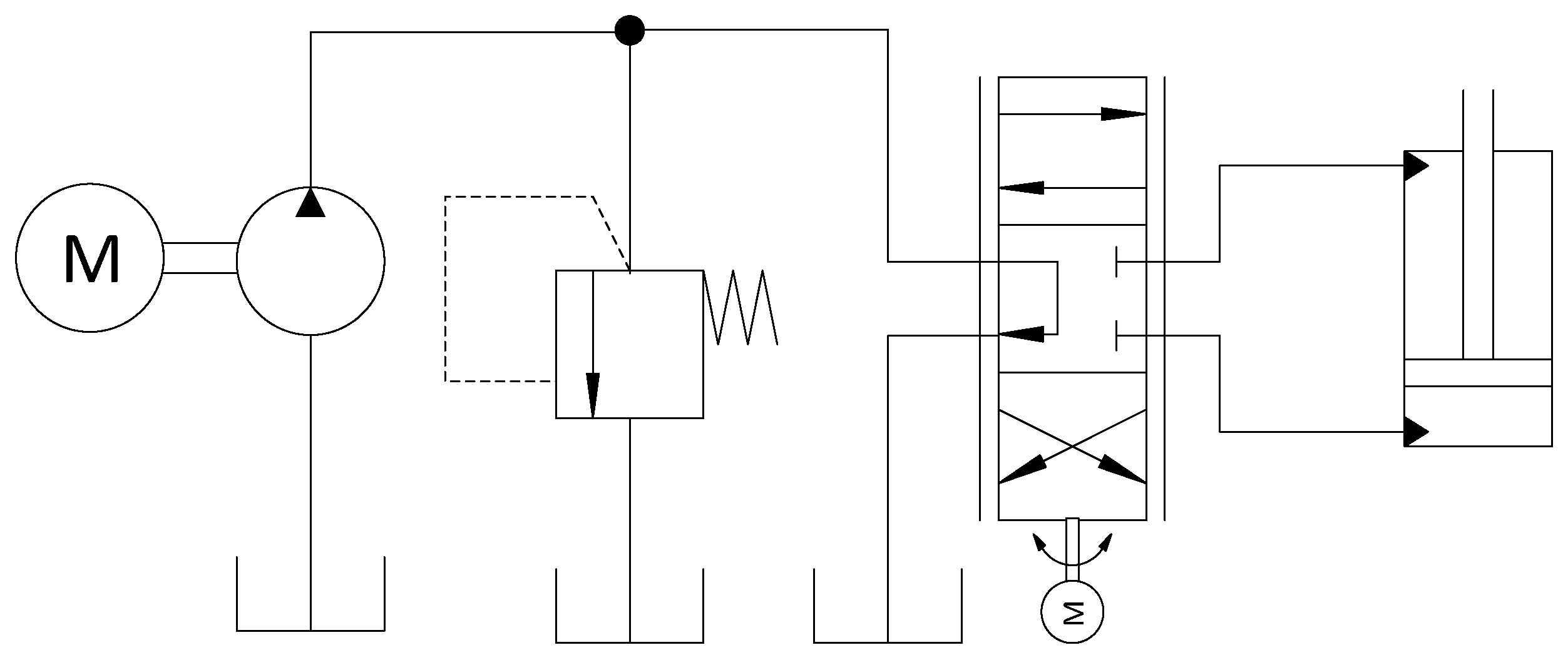
One limitation of the available systems is in the area of control. Typically, the pump is run at relief pressure and the flow is controlled by a rotary open-center valve, actuated by a hobby servo (as shown in
Figure 1). These systems are not very efficient (due to throttling losses and inability to recover energy from overrunning or braking loads) and exhibit a strong load sensitivity (low stiffness and bandwidth). This may be appropriate for a “toy” excavator but is not appropriate for “serious” applications such as robotics, prosthetics, or similar.
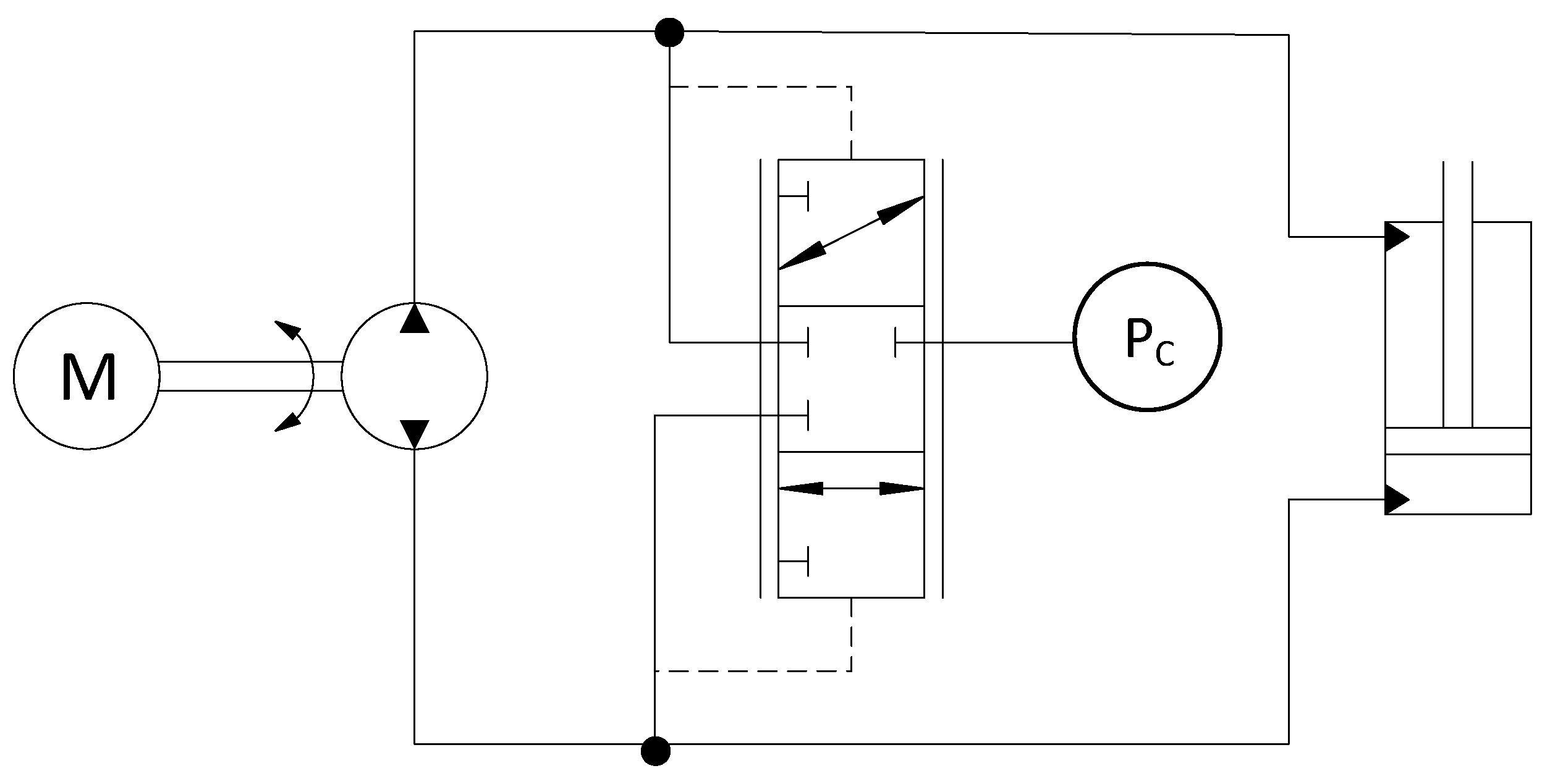
We, therefore, endeavored to create an electrohydrostatic actuator (EHA), which directly couples pump and actuator (see
Figure 2) [
2,
3]. With no flow control valve, the flow to the actuator (and therefore its velocity) is controlled by the pump speed. These systems are common on large-scale systems [
3] and are known for high efficiency, low load sensitivity, and very high specific power and force. One complicating factor is the asymmetric nature of typical single-rod hydraulic cylinders, with different flows entering and leaving the cylinder, necessitating a component to sink or source the unbalanced flow. While many options exist to achieve this function [
4,
5,
6,
7,
8,
9,
10] a common approach is an inverse shuttle (also known as a hot oil shuttle valve), which connects the lower pressure of the two cylinder ports to a reservoir or charge pump. Unfortunately, these components do not exist in the size range or price appropriate for low-cost miniature systems, so we were required to design and produce our own (as described in a later section). Due to the low production quantities expected and the requirement of a very low-cost valve, we investigated the option of additive manufacturing (3D printing) of a plastic valve.
The benefits of additive manufacturing technologies are gaining recognition in the field of fluid power. Direct metal laser sintering (DLMS) and selective laser melting (SLM) of powdered metal material have benefits in the manufacturing of low production or specialized hydraulic components such as manifolds, valve blocks, and valve spools [
11]. This reference explains that manufacturers are producing valves using additive manufacturing methods to take advantage of improved efficiency, smaller packaging, and material usage over valves made from traditional methods. This reference addresses only metal additive manufacturing methods, however, and all valve components require finish machining. In another example, SLM printing was used to improve material usage and packaging by incorporating hydraulic circuits into the mechanical structure of the thighs and pelvis of a human-sized wheel legged robot to avoid hydraulic oil lines interfering with joint movement [
12].
Plastic 3D printing has also been utilized in soft robotics and biomedical applications. The ability to 3D print solids and liquids simultaneously presents the advantages of easily constructing more reliable and intricate components, as demonstrated in the fabrication of a small hexapod robot, which required no assembly after printing [
13]. Plastic 3D printing has also been used to make micro biomedical check valves [
14]. The valves are a very simple three-piece assembly with an assembled diameter of 3 mm. Multi material additive manufacturing has been used to print hydraulic actuators with integrated seals safe for medical applications [
15]. These examples show how 3D printing is being utilized to produce very low-pressure hydraulic components in ways not possible by traditional manufacturing methods.
There are several examples of plastics in fluid power component applications. Stryczek et al. [
16] document the successful use of plastics produced by injection molding for a gerotor pump, pressure relief valve, directional control valve, and hydraulic cylinder components. They also note the advantages of plastic components over metal include weight reduction, noise and vibration reduction, improved tribology, self-sealing properties, and resistance to water and harsh chemicals. These components were suitable for pressures up to 6 MPa and flow rates of 1–15 L/min. The injection molded pressure relief valve is further documented by Marciniak et al. [
17], showing successful computational fluid dynamics (CFD, finite element method (FEM), and experimental test results as well as a comparison to an industrial metal relief valve. Another paper from the same research group investigates the flow phenomena in a throttling valve 3D printed from poly(methyl methacrylate) (PMMA) at flow rates up to 10 L/min experimentally and numerically using CFD [
18]. They note that some downfalls of 3D-printed plastic include lower strength and larger deformation, and materials such as polylactic acid (PLA) do not have sufficient hardness to form sharp edges. The flow rates in these examples are larger than those of interest for small scale electrohydraulic actuators. These papers also cover very little detail on the manufacturing methods of the components, particularly regarding finishing machining after 3D printing.
Costas’ M.Sc. thesis [
19] covers some details of the design and manufacturing of a small-scale plastic 3D-printed lobe pump, soft actuator, gate valve, and servo steering valve for the construction of a scale model forklift. This is perhaps the most relevant source to be found to addressing the practical aspects of plastic 3D printing such components. Four different 3D printer types were utilized, noting the strengths, weaknesses, and applicability of each. Although details were given for the practical manufacturing considerations using 3D printing, little information was given on any finishing requirements of the components post-3D printing prior to assembly. Furthermore, with the broad scope of designing and manufacturing the several different components, little consideration was put into optimizing the efficiency of the hydraulic systems. System stability was considered in the design of the power steering servo-valve, though no detailed analyses were shown. Costas (2018) shows the applicability of 3D printing in the design and construction of scale hydraulic components, leaving way for the design and analysis of a novel 3D-printed inverse shuttle valve for use in small scale electro-hydrostatic actuators.
This literature reviewed here establishes the advantages, applications, and examples of 3D-printed hydraulic component, as well as gaps in the current published work. Few examples of small-scale 3D-printed plastic hydraulic components have been identified in the literature, and none were found to be used for pressure-actuated valves such as the inverse shuttle required for an EHA. This leaves much room for continued analysis and development of plastic, 3D-printed valves in electro-hydrostatic actuators.
2. Materials and Methods
2.1. System Description
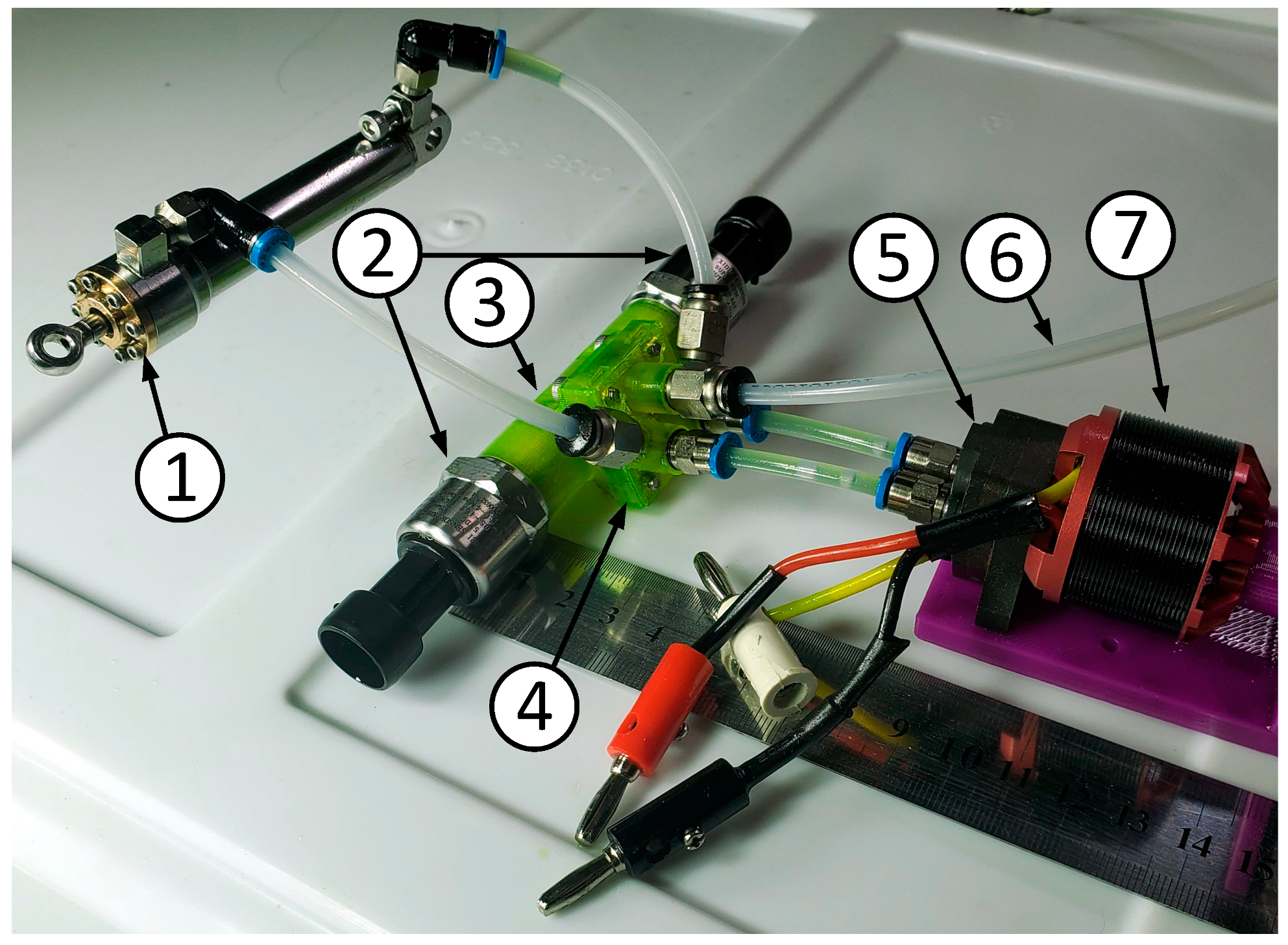
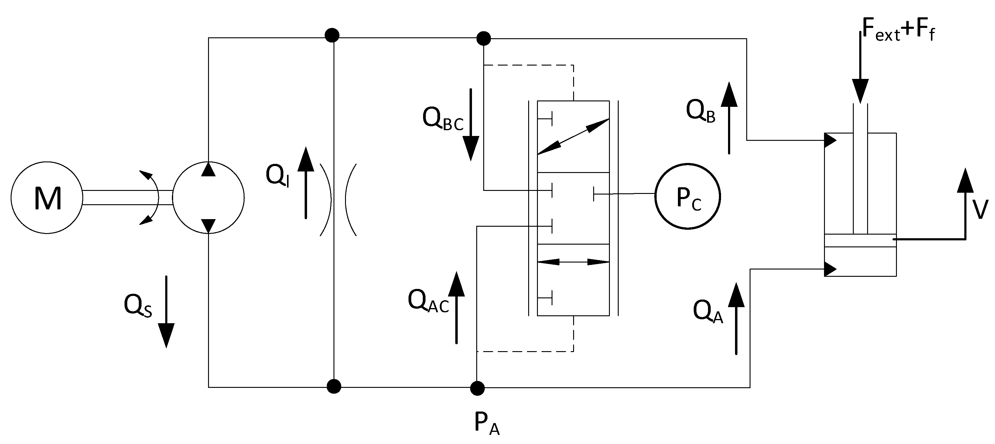
The prototype system schematic is shown in
Figure 3. The fixed displacement (0.17 cc/rev) gear pump is driven by a variable speed electric motor, in this case a permanent magnet motor (commonly referred to as brushless direct current or BLDC). The pump and motor were purchased as a matched set, with a rated pressure of 4.5 MPa. For research purposes, we drove the motor using an ODrive 24 V motor controller [
20], but this could be easily replaced with a low-cost BLDC electronic speed control (ESC) unit.
A commercially purchased hydraulic cylinder was used as the actuator, with 10 mm bore diameter, 4 mm rod diameter, and 50 mm stroke. This cylinder was provided without a technical datasheet but appears to have a hard, low-friction piston seal (perhaps polytetrafluoroethylene, PTFE) and has a soft elastomeric rod seal, likely nitrile rubber.
The single asymmetric hydraulic cylinder’s unbalanced flow is handled by the inverse shuttle valve. This valve connects the cylinder port with the lower pressure to the low-pressure supply. For testing purposes, this low pressure was supplied by an external pump, but it is believed that it would be possible for this to be replaced with a reservoir or accumulator (see
Section 4). The valve casing was 3D printed from polyethylene terephthalate glycol modified (PETG) using a Prusa i3 mk3 fused filament printer, at a layer height of 0.10 mm and 100% infill. The casing was produced with optional pressure transducers forming end caps, threaded into printed threads. Two versions were tested, as shown in
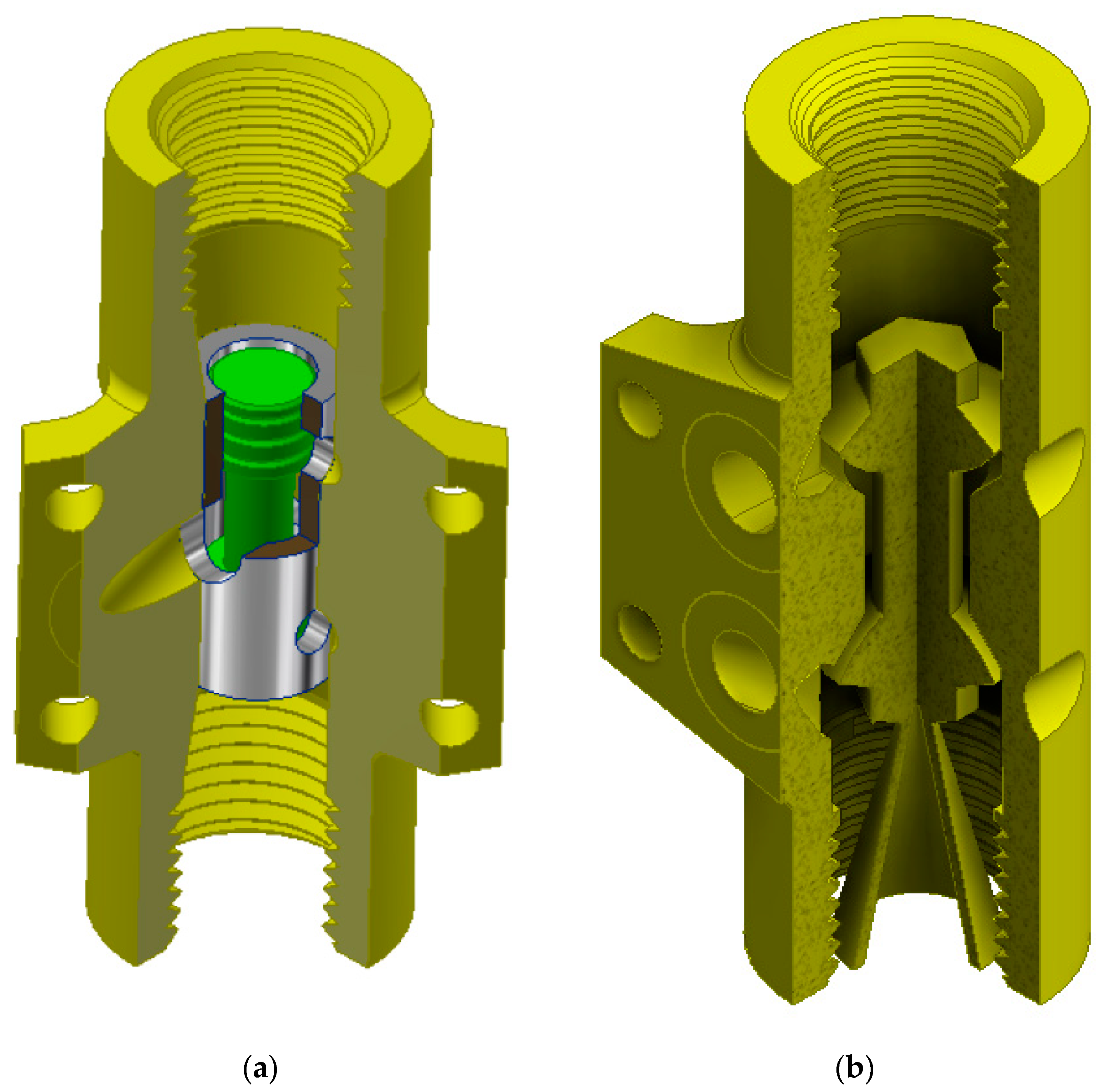
Figure 4. Model A was designed with a steel sleeve and spool that can be inserted into the 3D-printed casing. The spool must be machined but can be produced inexpensively (the authors received a quote to produce spools for USD 2 each, in large quantities). The sleeve can be produced from seamless steel tubing with hand tools (including matching the hand-reamed bore diameter to the spool diameter with an appropriate clearance).
Model B was entirely 3D printed with the captured spool printed in place. The authors believe this is the first hydraulic valve to require neither assembly nor finish machining. This design uses two connected hemispherical poppets, which seat into conical seats. The hemispherical shape allows for good sealing even with angular misalignment of the unguided poppet. Once designed, the cost to produce this valve is nearly negligible, with a material cost of less than USD 1 and requiring less than 4 h of unattended printing time. For those without access to a 3D printer, numerous commercial enterprises can produce this part at minimal cost. We received commercial quotes for single quantities as low as USD 13 plus shipping and less than USD 2 in bulk quantities.
The valve designs presented here were intended to prove the concept and are not optimized (see
Section 4 for discussion of further work).
All connecting lines are nylon tubing, rated for 4 MPa, which sets the safe working pressure of the system. Rather than physical relief valves to enforce this pressure limit, we used the measured pressure to limit the pump velocity for this prototype. This system is not entirely reliable, so rupture discs or other weak points could be included in a production version to ensure safety. Alternately, the motor current could be limited in order to limit pressure if pressure measurement was not required.
Instrumentation used included low-cost pressure transducers (Xidibei model XDB303, USD 15) with a full-scale pressure of 4 MPa and 0.5–4.5 V output. We also used the linear potentiometer from an Actuonix L16-P electrical actuator to measure the cylinder displacement. All signals were recorded using a Measurement Computing 1608FS-Plus USB data acquisition system.
2.2. Steady State Model
This section presents a model for flows and pressures at steady state, neglecting acceleration, valve dynamics, wave effects, etc. Referring to the nomenclature in
Figure 5, assuming incompressible fluid, continuity requires
where
is the head-end piston area and
is the rod end piston area.
An equilibrium force balance on the piston results in
where, following an equation modified from [
21], the effective friction force is given by
where
is the Coulomb friction,
is the dynamic viscosity,
is a pressure-dependent friction term, and
is a viscous damping term. Fluid friction in lines and fittings is also lumped into
(which should have a small effect). We investigated including a turbulent friction term (proportional to
but found its value to be statistically indistinguishable from zero in experimental tests. Likewise, a
friction term was considered but was also indistinguishable from zero, likely due to the hard piston seal, as compared to the deformable elastomeric rod gland seal.
This model lumps all internal leakage (i.e., pump, valve, and cylinder) into
and all external leakage and valve flow into
and
. Laminar internal leakage is given by
where
is the leakage resistance. The external leakage and valve flows are given by
where
and
are the leakage resistances and
and
are flow resistances with the valve open (including valve resistance in parallel with any external leakage). This assumes that the valve spool is fully displaced and does not take on any intermediate positions. As this spool has no centering spring, absent large static friction or flow forces, this should be a good assumption at equilibrium. This also assumes that all external leakage goes to the charge pump pressure not atmospheric. This introduces some inaccuracy, but we did not observe any significant leakage through the pump shaft seal or cylinder rod seal, so it is believed that leakage through these paths will be small relative to the leakage through the valve.
The above equations constitute a nonlinear system of algebraic equations that can be numerically solved for the cylinder velocity, given the commanded pump flow, charge pressure, and external force.
The fluid system efficiency can be evaluated as the ratio of fluid power generated by the pumps to the fluid power delivered to the load:
Friction in the cylinders can be included in the overall system efficiency, defined as the ratio of output mechanical power to fluid power generated by the pumps:
Normally, the input power would be defined as the shaft power, but due to the close coupling of the pump and motor, the shaft toque could not be measured. Therefore, this measure of efficiency does not include the mechanical efficiency of the pump (but does include losses due to pump leakage).
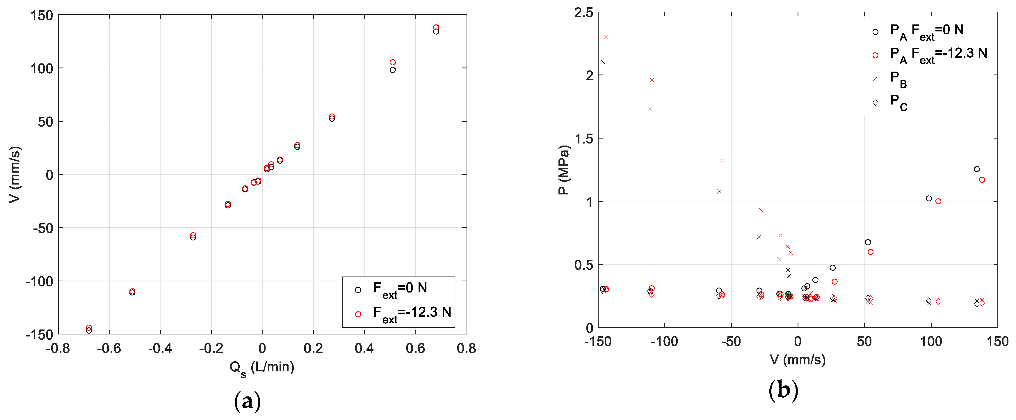
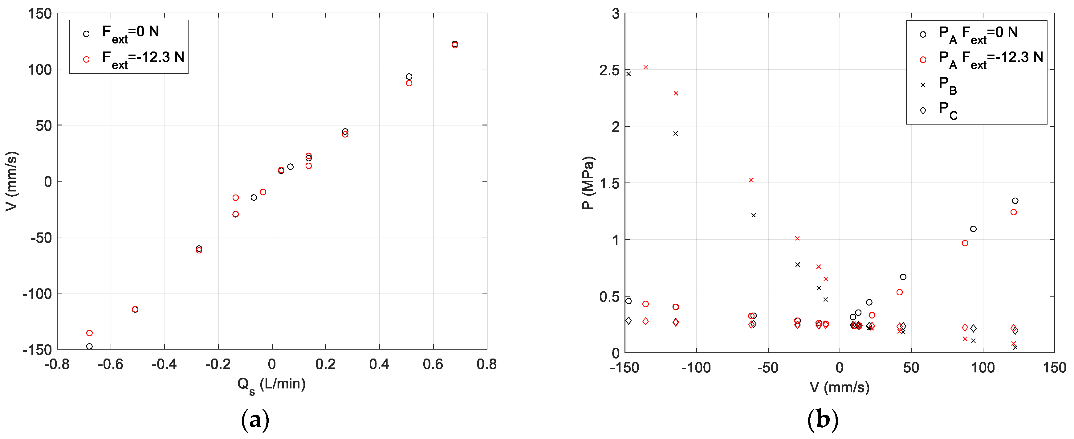
2.3. Steady State Experimental Test
In order to validate the model and experimentally measure the performance of the system, a steady state test was performed. A known weight was hung from the actuator and a constant pump speed was commanded. After the system velocity and pressures reached steady state, the cylinder position and pressures were measured. The cylinder velocity of obtained by differentiating the position signal, smoothed by a 50 Hz low pass filter. These signals were then averaged over the time period until the actuator neared end of stroke.
These data were also used to obtain some model parameters. The cylinder pressures were used to obtain the friction force , and together with the measured velocities, were used to obtain a linear-in-the-parameters least squares fit for the cylinder friction parameters , , and . A nonlinear numerical optimization (using the MATLAB fminsearch() algorithm) was performed on the measured pressures, velocity, and commanded pump speed to obtain the best-fit valve restriction and leakage. Uncertainties in these estimated parameters were calculated using a bootstrap method for p = 0.05.
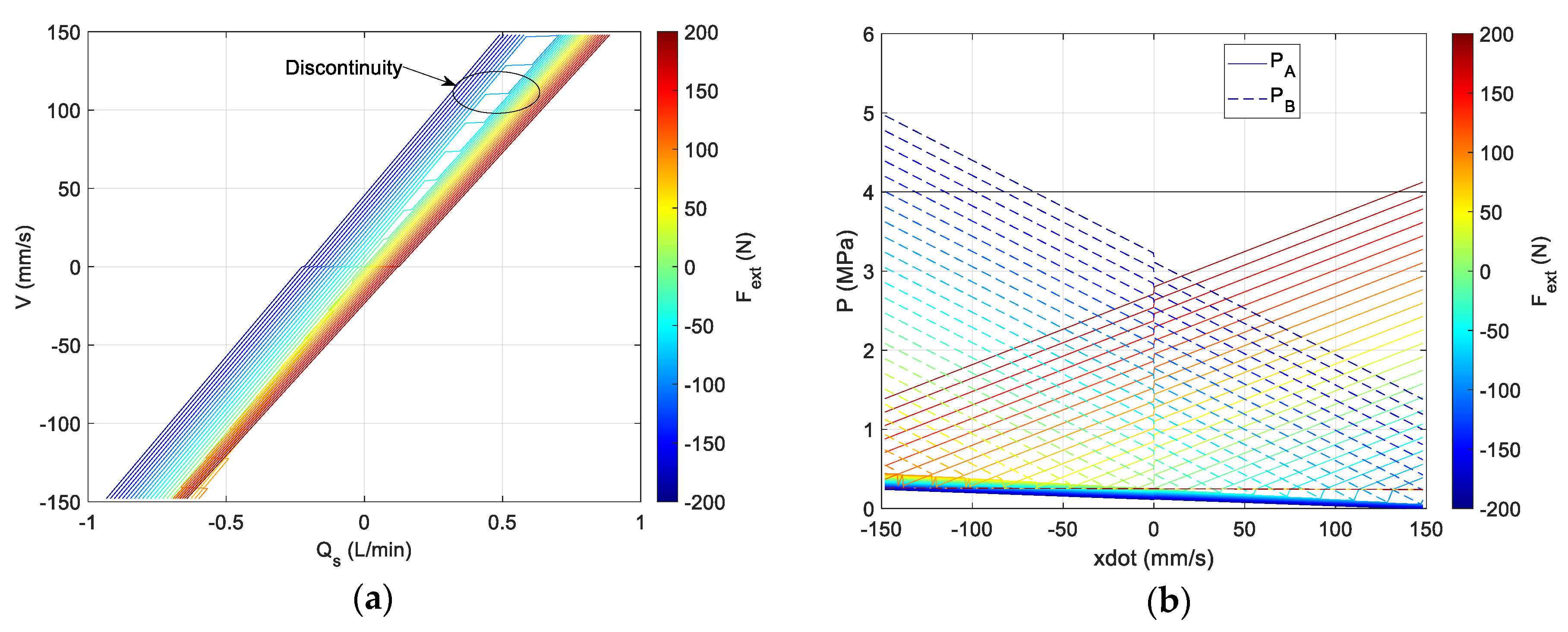
4. Discussion
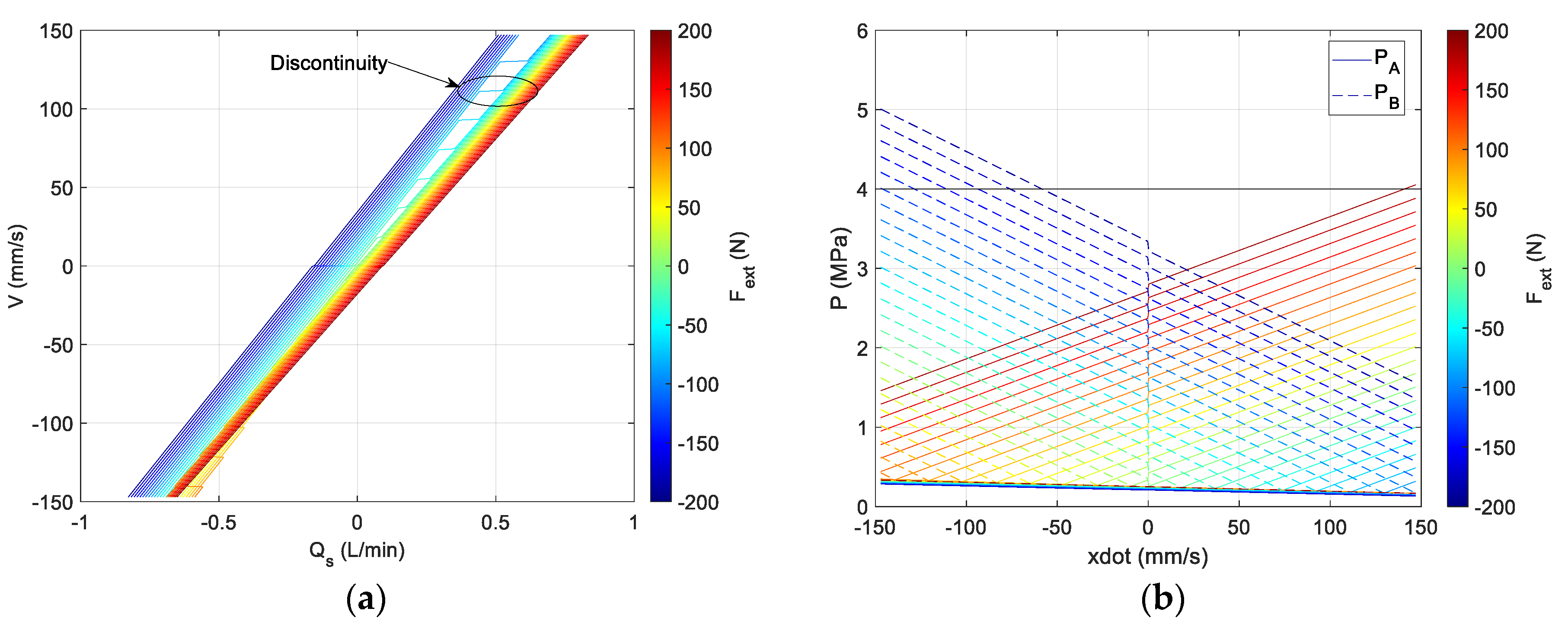
The results shown above demonstrate that the system works as intended. The actuator velocity is largely linear with the pump flow command, with a small load dependence. If desired, it is expected that this load dependence can be mitigated to a large extent by a feed-forward compensator based on measured pressures. As identified by previous work [
22,
23],
Figure 8 and
Figure 9 show a discontinuity in the velocity as the valve moves from one regime with
where the ideal velocity is based on
, to the other valve position when
where the velocity is based on
. This effect is small for the system presented here as the ratio
= 1.19 is close to unity, and also, due to the fact that the valve spool has no centering spring, the valve rarely exists in a centered position with either both orifices open or closed. This discontinuity has also been identified as a source of instability for closed loop applications [
22], but preliminary dynamic simulations (presented in [
24]) have indicated that the level of leakage that exists in this valve is sufficient to stabilize the system.
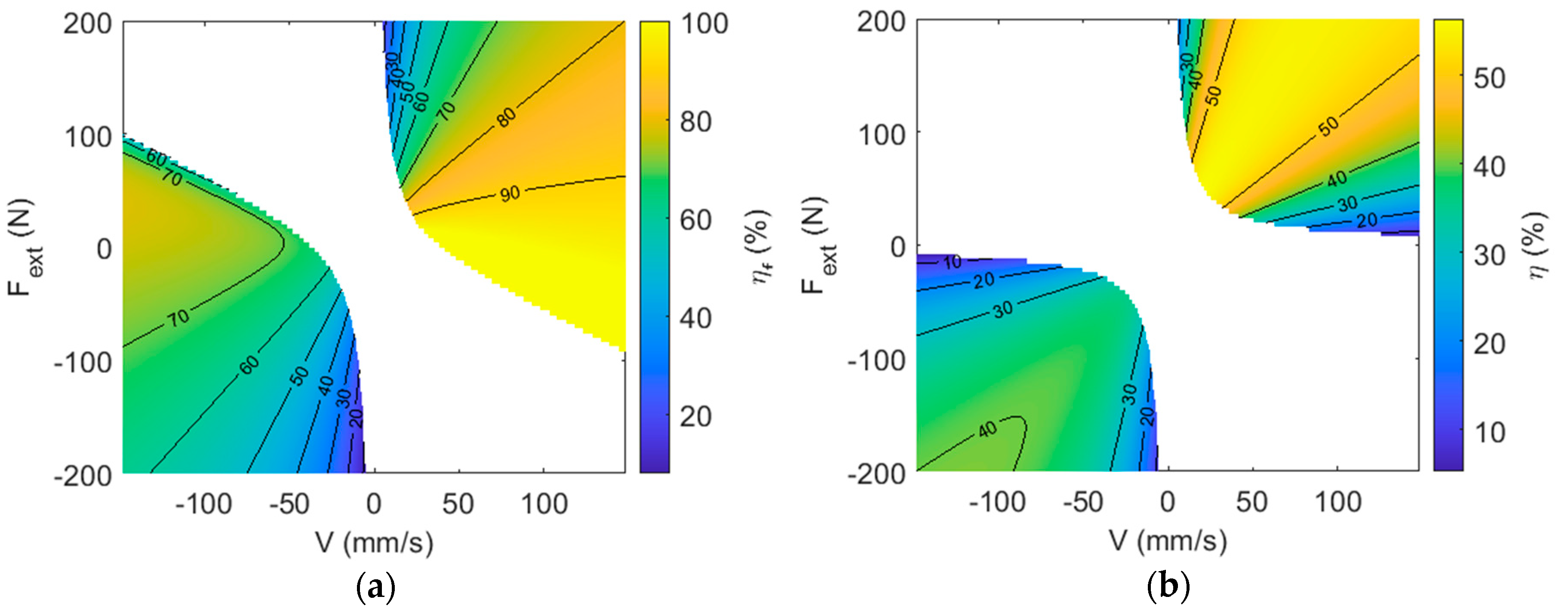
The system efficiency plots in
Figure 11 show reasonable values, although there is room for improvement over the unoptimized valve. As shown in
Figure 11a, the efficiency of the fluid system is relatively good, with the major energy losses occurring due to cylinder friction. As shown in
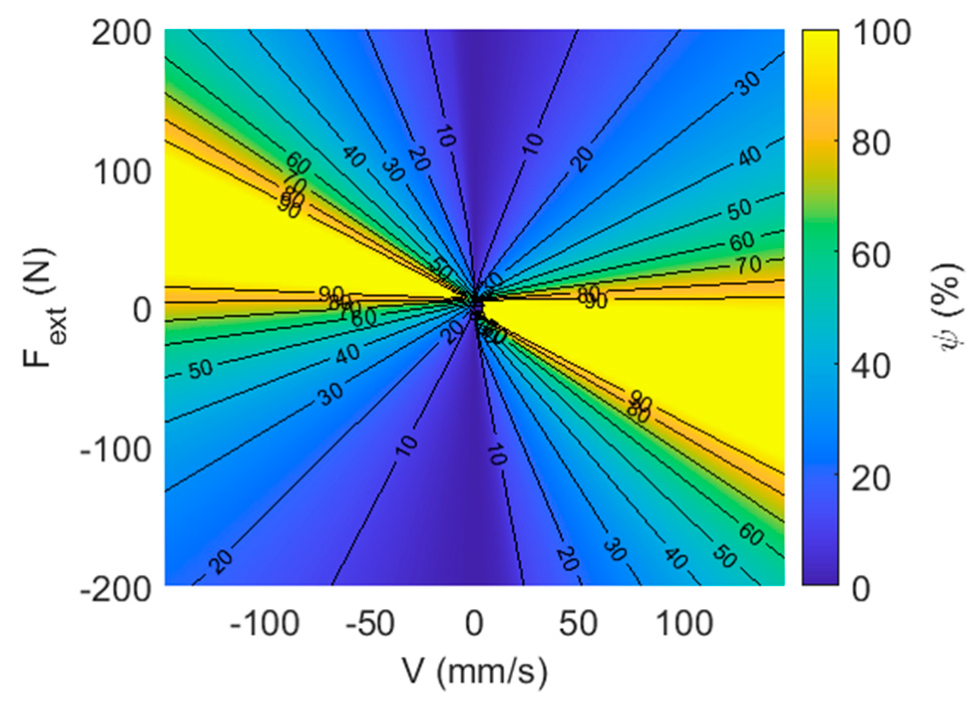
Figure 12, the fraction of the system input power lost to cylinder friction (defined here as
) is high over a wide range of operating points.
These results also show that there is little difference in performance between the machined steel spool and the 3D-printed valve. Although the large-quantity cost of a machined spool and sleeve is small, the 3D-printed valve has a very low cost, even in single quantities. This presents the opportunity for much more precise customization of a valve to an application, both in terms of matching the valve dimensions to the system’s size and capacity, but also in terms of tuning characteristics that are important to dynamics and stability such as leakage, mass, damping, etc. Either valve approach lends itself to integration of many functions into a single manifold block.
The long-term reliability and performance of the system is not yet established, but the choice of a poppet for the 3D-printed valve rather than a spool mitigates some of the drawbacks of plastic valves. Erosional rounding of sharp edges is not a concern and, in fact, may improve flow characteristics. The poppet automatically compensates for wear on the sealing faces as long as the wear occurs evenly, and eroded channels do not form.
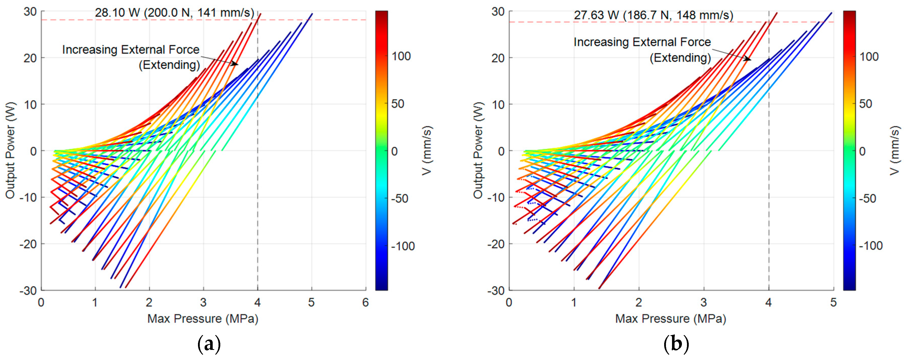
Compared to an electrical screw actuator with a size similar to the hydraulic cylinder, the EHA velocity is 4.6 times faster, the maximum force is 5.9 times greater, and the peak output power is 34 times greater. This is somewhat underestimated, as the EHA’s velocity as tested was artificially limited by the 24 V power supply and drive electronics; the maximum speed as tested was 4000 rev/min, but it is unknown how much faster the motor could be operated before it is limited by overheating, pump inlet cavitation, excessive wear, or wire insulation breakdown.
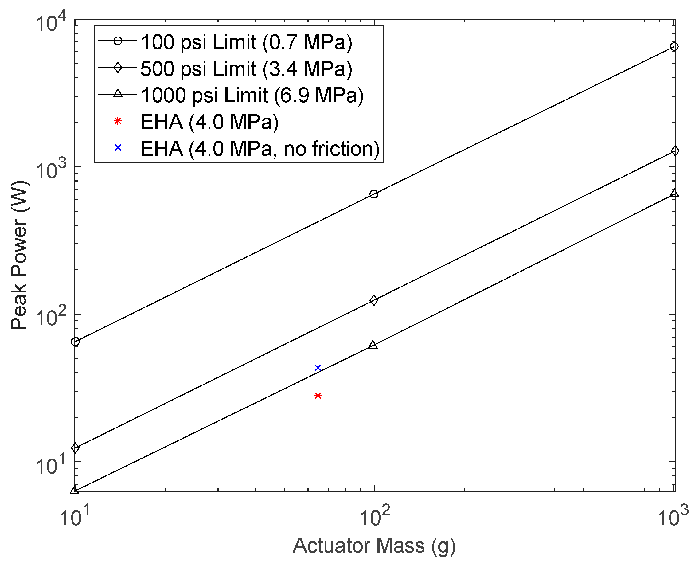
The EHA’s high specific performance is even greater if only the final actuator is considered, which is important for applications such as hand tools where the pump and valve weight are less important than the actuator weight. On this basis, the EHA exhibits five times the actuator-only specific force and nearly 30 times the specific power. The actuator specific performance is comparable to the predicted limit published in [
25], as shown in
Figure 13.
Table 7 presents a cost estimate for the system. This represents approximate external costs to produce low quantities of a valve B system, not including labor or engineering time. This also assumes that the charge pump can be eliminated. These values should be viewed as approximate at this time as we do not have accurate costing, since many of the components that we purchased were selected for research purposes rather than low cost. For example, the ODrive motor drive system is a very flexible system with monitoring capabilities (USD 120), but the functionality could be provided by a USD 25 electronic speed controller (ESC).
Future Work
This paper is largely intended to present a proof-of-concept. The system works but is not yet optimized. Further work includes the following:
It may be possible to remove the charge pump system, replaced with a reservoir at atmospheric pressure or a low-pressure accumulator. As tested, the minimum pressure recorded was 33 kPa below the charge pressure for Valve A and 149 kPa for Valve B. If the same pressure drop existed and the charge pressure was reduced to atmospheric, the cavitation number (
using absolute pressures) would be 2.0 for the Valve A system and −0.3 for Valve B. While cavitation initiation is a complex subject, the critical cavitation number is usually less than 1 [
26], indicating that the Valve A system may be able to operate as-is, but Valve B cannot. The inlet path for Valve B was not optimized, and it may certainly be possible to reduce the restriction enough to operate at atmospheric without cavitation. A charge pump or other device may still be desirable in high-performance systems requiring high bandwidth, as it has been noted that elevating the minimum system pressure can have a significant beneficial effect on system stiffness [
4].
Friction is a significant power loss, especially at high speeds (as shown in
Figure 12). This is composed of cylinder mechanical friction and flow losses. It may be possible to reduce cylinder friction by replacing the elastomer rod seal with a harder, low-friction PTFE seal. This may also reduce the discontinuity due to static friction. The flow paths may also be optimized, as there are a number of choke points such as the cylinder port fittings.
Valve leakage has not been optimized. Although some leakage may be desirable for dynamic stabilization purposes, this also represents a power loss and should be reduced where possible. The 3D-printed poppet valve geometry has not been optimized, but the additive manufacturing process allows for great flexibility in design, including possibilities such as negative poppet angles or shapes to promote rotation in order to equalize wear.
System dynamics have not been optimized, including implementation of closed-loop or feed forward velocity control.
The valve has not been optimized from a strength of materials point of view. While the valve was designed and tested for safe operation to 4 MPa, it is unknown how great the safety factor is or whether the system is susceptible to failure over time.
Packaging can be improved, including eliminating the tubing between pump and valve, and possibly between valve and cylinder (if space at the actuator exists in a given application).
Pressure transducers currently represent more than 20% of the system weight. These could be replaced with smaller sensors or eliminated if not required from a measurement or control perspective. Eliminating the sensors would likely require the addition of relief valves or motor current limiting.
Investigating the application of the sleeved spool in other applications. If the same element can be used in a wide variety of applications, it may be reasonable to produce a sufficient quantity to justify the machining set-up cost. This low-cost element may then be inserted into a wide variety of 3D-printed plastic manifolds.
The long-term wear properties of the plastic valve are not yet known. This may be a reason to use the sleeved spool version instead of the 3D-printed poppet. It may also be a reason to change the material to a more resilient plastic. Three-dimensional-printed steel and aluminum have become more commercially accessible recently, and if prices continue to decrease, this may become another feasible option in the medium-term future.
While we have no specific reason to doubt the extrapolated force and power limits of the system, limitations of our current testing apparatus prevented experimentally verifying these values.


