Article

Hydraulic Switching Control Supplementing Speed Variable Hydraulic Drives

1
Institute of Machine Design and Hydraulic Drives, Johannes Kepler University Linz, 4040 Linz, Austria
2
Linz Center of Mechatronics GmbH, 4040 Linz, Austria
*
Authors to whom correspondence should be addressed.
Actuators 2020, 9(4), 129; https://doi.org/10.3390/act9040129
Submission received: 30 October 2020 / Revised: 30 November 2020 / Accepted: 2 December 2020 / Published: 4 December 2020
(This article belongs to the Special Issue Electro-Hydraulic Actuators)

Abstract

:
Primary control of linear motion by variable speed electric motors driving a hydraulic cylinder via a constant displacement pump is an established and successful concept with a frequent use in industry. One problem arises when low or zero motion speed has to be realized under high pump pressure conditions. Such load scenarios occur frequently in certain pressing processes, e.g., for sintering or veneering. Most pumps have a lower speed limit, below which critical tribological conditions occur which impair lifespan and efficiency. In addition, pump speed control and pump fluctuation suffer from the mixed lubrication conditions in such an operation range. For a circumvention of such low speed pump operation, a digital valve control concept is presented and studied in this paper. Valve control is used in load holding phases with low speed. Pressure is provided by an accumulator which is charged by the pump in short charging cycles at reasonable pump speeds. It is shown that the mean control error during load holding phase lies within the desired band and the fluctuations of the control force are lower than those of the pump control. In addition, the unfavorable pump operation conditions can be avoided via digital control.

1. Introduction

Hydraulic drives with primary control based on variable speed motors and constant displacement pumps are broadly used in industry. Early proposals from the scientific side, e.g., [1,2], found rapid acceptance in industry approximately from the year 2000 onwards. Up to now, academic work has addressed several aspects, ranging from studies on the advantageous of the use of this technology for specific applications [3,4,5,6], special circuitries to compensate flow mismatches of double stroke cylinders [7], and motor [3] and pump design issues, to general system performance considerations [8,9,10]. The excellent usability of this motion control technology is underlined by its strong growth in industrial use and the fact that many hydraulic components and system providers but also automation companies deliver appropriate components and complete drive systems. The concept of combining powerful speed variable motors with a hydrostatic transmission instead of a mechanical transmission to generate and control mechanical motion has some basic advantages: the unrivalled robustness of the hydraulic cylinder, the good energetic efficiency, the possibility to employ mature and widely available electric motor control algorithms and electronics, the ease of generating high forces, passive load holding without a motor torque, simple gear shifting by switching a double stroke cylinder from rapid feed (plunger mode) to work feed, fast emergency stop by actuating fast bypass valves, and the higher flexibility of geometric arrangement of the motor and actuator for a favorable system design, to name just a few.
The symbiotic combination of electrical and hydraulic drives and actuation principles gives a great opportunity to establish advantageous solutions for special requirements, which both of these drive technologies cannot achieve. Several industrial applications require a fast motion in some operation phases, but a very slow motion yet with a high load in other phases. Typical examples are presses in sintering plants or for ski production and veneering presses. Sinter presses are operated, for instance, by Miba Frictec to produce sintered parts for the automotive industry. The required pressing pressure during the sintering process must be kept very precisely and traceably at the desired value to achieve high quality parts. Opening, closing and pressing of the press is realized by a conventional speed variable electric motor in combination with a hydraulic pump. Pressing and holding takes place at 250 bar and accounts for a considerable portion of the cycle time. After loading of the parts and closing of the press, the pressure at the unit is initially increased to 250 bar and held there for about 90 s. In this phase, the sinter parts are heated up to a certain temperature level, which requires a permanent control of the pressure to compensate for the thermal expansion. It is well known that such processes are adverse for electric motors [11] and pumps [12]. High torques require a high current in electric drives. Theses currents heat up the engine and cause losses; in turn, efficiency is bad. In addition, motor cooling might suffer from such conditions if cooling fans connected to the motor shaft provide sufficient cooling conditions. Most pumps have a bad efficiency at low speeds [13] and their lifespan is impaired by mixed friction-caused wear in the sliding parts [14,15,16]. The latter problem motivates pump vendors to exclude slow speed rotation of some pumps from liability. In [17], this problem is addressed by modeling of the tribological state, and of the journal bearings of gear pumps in particular, to detect critical situations.
A further performance criterion, particularly of many industrial drives, is high precision of the final position or force, such as for the sinter presses described above. Such requirements may be difficult to be fulfilled by a speed variable drive at very low speed. Pump flow ripples or motor torque ripples due to cogging are periodic disturbances which need extra control effort to be compensated. In a situation where pump leakage exceeds the flow required for motion control, the uncertainty of the leakage requires measures in the control algorithm to handle that uncertainty. If asynchronous motors with frequency converters are used, the precise control of slow speeds may be a big challenge, with high demands also on power electronics.
For these reasons, it may be advantageous to hand over such operation phases to a separate actuation concept which can fulfil the requirements more easily and effectively. One option could be to switch to a much smaller pump which delivers the low flow rates at easy to handle motor speeds. This would decrease the torque requirement on the motor and the ohmic losses of motor currents. It requires a second pump and a valve to handle the engagement and disengagement, at least of the large pump. Another concept is to use valve control instead of primary control. Since power is low, the hydraulic energy to supply these phases could be stored in a hydraulic accumulator. Motor and pump have to run only in short charging periods at advantageous speed and torque conditions. Valve control can be done by continuous valves, i.e., by servo or proportional valves, or in a digital fashion by on–off valves. The review paper [18] addresses the low speed problem and proposes the development of appropriate pumps, capable of withstanding such operation conditions. It also presents a circuitry with two 2/2 proportional valves to drain off the difference of oil needed and delivered by the pump at acceptable minimum speed.
Basically, this concept is a combination of primary displacement and valve control. The operation of both branches is not necessarily disjointed. If favorable, both branches can also operate jointly. A useful application could be to improve the precision of pump control by adding or subtracting flow to the actuator by valve control, either permanently or in short precision demanding periods only.
This additional “valve branch” in the system generates additional costs: investment, risk of failure, control effort, maintenance costs, and energy due to additional losses. These costs must be outweighed by the advantages: higher precision, reduction in motor and pump losses, possible savings due to missing or reduced cooling costs, higher lifespan of pumps, or lower noise emission.
This paper studies a switching type valve control. The method has been developed to solve problems of presses in industry which have been equipped with variable speed pump control in the mentioned low speed range for two industrial companies. The production plants of these companies did not allow a sound experimental evaluation of the relevant hydraulic processes. Therefore, the experimental investigation was done at a test rig which offers sufficient access to conduct the required measurements.
The drive concept in general and the specific version realized by the test rig are described in Section 2. The test cases, the evaluation procedure, and some measurement results are discussed in Section 3. Section 4 deals with conclusions including remarks concerning the useful application of this hybrid control concept.

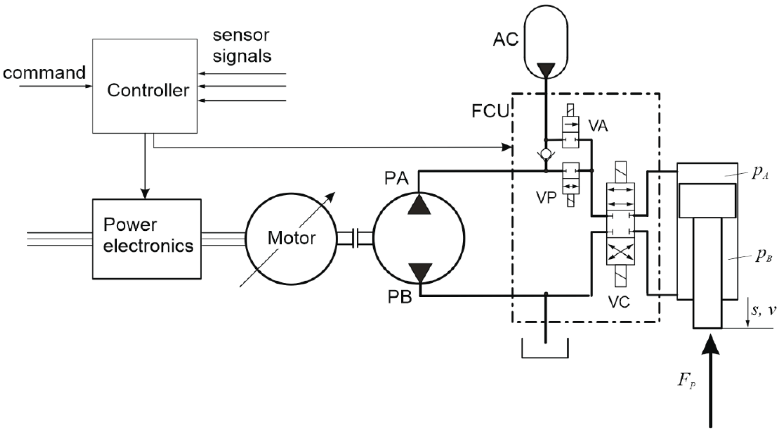
2. Combined Primary and Switching Control of a Linear Hydraulic Drive

2.1. Drive Architecture Tailored to Operation Conditions

The basic architecture of the drive concept under study is sketched in Figure 1. It is conceived for press operation with three operation phases: (I) a press phase, (II) a load holding phase, and (III) a return phase. Motion control in phases (I) and (III) is done by the speed variable electric motor driving a two quadrant pump. Phase (II) is handled by valve control. Then, valve VC controls the load by pulses whenever the load needs to be corrected in order to stay within a tolerance band. Valves VA and VP are on in phase (II), allowing the pump to charge the accumulator and connecting it to the control valve’s high pressure port. This is an open circuit with a standard reservoir to ease oil conditioning and management, which are critical issues for meeting the machine uptime requirements of presses running more or less permanently. The preferable valve type for VC depends on the quantitative operation conditions. In case of very low average flow in phase (II), leakage of a leaking valve may overcome the energy consumed by the process. Then, seat valves may be a better choice. They not only reduce energy consumption but also the times when the motor and pump run to charge the accumulator and create some noise in an otherwise silent machine.
The use of valves and selection of proper valve types is a major issue in the design of speed variable hydraulic drives. For instance, the handling of flow mismatches in case of single rod cylinders may be solved quite differently. The use of piloted or electrically actuated valves (e.g., [19,20]) may be an alternative to concepts with two pumps (e.g., [21]). Load holding [20] or a “gear shift” by exploiting the plunger mode of a single rod cylinder (e.g., [22]) are exemplary functionalities which hydraulics can realize in a simple, durable and cost-effective manner. The identification of a favorable architecture and the best suited components depends strongly on the case specific operation scenarios and the general conditions under which a machine has to work. The concept under study is useful when the relatively short phases with high actuation power are followed by phases with high loads but no or very slow motion, hence with low power consumption.

2.2. Basic Performance Considerations

In the context of this study, pump degradation by excessive wear and efficiency in the low speed versus a normal speed range are of particular interest. Ref. [13] gives a useful overview of the efficiency of different displacement pump types as a function of the differences in pressure, but not for low speeds. Such scenarios’ implications on efficiency and wear rate are hardly addressed in published work, because it is an unsuitable operation range for many pumps. Reliable prediction of wear under practical conditions is hardly possible due to the strong influence of oil contamination and run-in. As long as pumps suitable for low speed are not available, such low speed operation must be avoided in heavy duty machines. Besides the concept proposed in this paper, this can be done by a line parallel to the pump which drains the pump flow surplus to the tank via some hydraulic resistance. For long load holding phases, this causes a substantial additional loss if the minimum allowed pump speed is much higher than the average pump speed needed to deliver the flow in this phase at reasonable pump volumetric efficiency.
Load scenarios considered in this paper may be exemplified by the speed and load profiles given in Figure 2. In a first positioning phase that is free of load, a tool is brought into the working position. Phase I, possibly done at lower speed v1, is the real working phase with a substantial power demand where the speed variable drive can exhibit its advantages. The essential parameters to decide on the appropriateness of an additional valve control unit are the force level and duration of phase II. If both parameters are high, overall cycle efficiency with solely pump control is low in view of the high internal leakage. A drain off line to keep the pump at tolerable speeds worsens this situation. Other sources of leakage, such as valves, have the same effect. Therefore, for high duration time t2, leakage avoidance is important for a good overall efficiency.
Selecting the best type of valve is a matter of motion speed v2 in phase II, valve leakage, required precision, and cost. Precise proportional or servo valves have a substantial leakage, due to zero or very low overlap of the metering edges. This leakage flow may be a multitude of the net flow required for motion generation in load holding. In such cases, seat valves operated in some switching control mode, like PWM, will be a better solution. However, such valves and control principles, respectively, may have difficulties in providing smooth motion and force, due to the interrupted flow. In the case of very low speed v2, this is no problem, even with switching valves which can operate at only moderate switching frequencies. The high precision in dosing very small flow rates, for instance also by exploiting the “ballistic mode” of valve control, gives switching control a superior control accuracy for force or position control (see, e.g., [23,24]). The higher the slow motion speed v2, the more likely pulsation problems will be. There might be a range of this speed where pump control is conflicting with the minimum pump speed condition and switching valve control above a tolerable level of pulsation of motion speed or process force. Basically, high switching frequencies help but require fast switching valves not available on the market. Other options are passive filters, properly integrated into the hydraulic system [25,26].

3. Experimental Tests

3.1. Test Setup

The actually used test rig deviates slightly from the basic architecture of Figure 1. An elevated lower pressure is used to avoid cavitation in the rod sided cylinder chamber. This chamber’s pressure drops quickly when connected to tank side due to its low hydraulic capacitance and may fall below tank pressure due to parasitic inductance in the hydraulic lines. The elevated pressure is realized by a low pressure accumulator, AC2, and a pressure relief valve, PRV. The two cylinder chambers, the accumulator pressures and the cylinder position are measured for control and for analysis purposes. The accumulator pressure signal is used to charge the accumulator and to keep its pressure between two pressure levels [pAc,l, pAc,u]. The valves V1, V2, V3 are seat type valves with no leakage. V3 has two functions: directional control and flow metering in valve control phases. For the latter, V3 is operated in PWM mode and a valve suitable for such hydraulic switching control was used. All used components are specified in Table 1.
Load simulation was accomplished by an equal stroke cylinder. Pressure in its chamber opposing the drive cylinder is passively controlled by two nozzles, which form a pressure divider circuit or just simple resistances to high or tank pressure by switching the two valves, VLP and VLT.

3.2. Control

With the test rig, according to Figure 3, the load holding can be done with either a displacement control or a digital valve control. The valve control uses a gas loaded accumulator as a high pressure reservoir, which must be pre-loaded by using the permanent-magnet synchronous motor (PMSM) driven pump. For this purpose, the oil is drawn from the tank by the pump located in between two check valves and, thus, directed to the high-pressure accumulator, AC1. The pre-loading process is realized with a two-level controller, which is enabled when the digital valve control is active, hence, no displacement control of the load is intended. If the pressure level in the high pressure line falls below a certain limit, the two level controller triggers a speed controller of the pump implemented on the frequency converter in order to produce a constant loading speed and flow rate, respectively. When the pressure level in the reservoir exceeds a certain limit, the pump is switched off again.
According to Figure 4, in phase I the drive performs a fast working motion under load, which is performed after it entered into contact with the load, e.g., the press object. In this phase, displacement control is applied handled by the electric motor and its controller, respectively, and the pump. For this purpose, the directional valve V1 is shut, V2 is opened and V3 is used to achieve the desired moving direction and, thus, to build up the pressure in the corresponding pressure chamber of the cylinder. This kind of motion control is realized with a simple P-controller, which is implemented on the CPU of the used industrial control unit. The set value of the position controller is linked to the frequency converter, where a speed controller and, furthermore, a cascaded torque controller produce the rotational speed of the motor, which drives the pump in order to achieve the flow necessary to position the load cylinder. In this phase, the differential flow of both working cylinder chambers is compensated either by the tank sided check valve or by the pressure relief valve (PRV), depending on the moving direction controlled by the valve V3. The load holding phase II is realized by either position control or force control, which in turn can be done by either displacement control or digital valve control. Each individual method is realized with simple P-controllers, of course, with individual controller parameters, which were adjusted empirically.
In case of digital valve control in the load holding phase, the valve V2 is shut, the valve V1 is opened and the valve V3 is operated in PWM mode at a switching frequency of 50 Hz. It is necessary to mention that the used SEC-6 4/3-way seat valve is not fast enough to completely open and close at such a high frequency. Still, it can be used for switching mode control because the valve’s dynamics are sufficient for so-called ballistic mode where the valve’s seat is actuated by short impulses generated from current pulses in the solenoid. The digital valve control is designed especially for load holding where only small flow rates are demanded and not for tracking control. Therefore, the duty ratios of the hydraulic PWM control signal are expected to be small and, especially, are limited to a ballistic operation in order to keep pressure fluctuations due to valve switching small. However, in the load holding phase, no large flow rates for the compensation of disturbances are expected. After the load holding phase, the drive, and thus, the valves V1, V2, and V3, are switched to displacement mode again in order to realize phase III according Figure 2 for a rapid movement back to the initial position of the process cycle.

3.3. Test Scenario

For evaluation of the primary control mode and the hydraulic switching control, a scenario which imitates a dissipative process under constant force control such as an injection molding process or a sinter press process was emulated. It highlights the advantages and limitations of the primary control mode and hydraulic switching control. Different states of the hydraulic circuit that simulate the process are shown in Figure 4.
At the beginning of each cycle the work cylinder is moved towards the lower piston (Figure 4a). The initial pressure in the bottom chamber of the bottom cylinder is 100 bar, which results from the last step of the previous cycle. As described in the previous section, the working cylinder is positioned using the displacement mode until a threshold of F = 2000 N of acting force on the bottom cylinder is reached (phase I). Then, the system is switched to force control and the desired force is applied to the piston after a short wait time of 0.5 s. Valve VLT is opened and oil is squeezed out through a small throttle to imitate the dissipative process (Figure 4b). This phase is referred to as phase II throughout this article. After a displacement of dx = 30 mm under constant force, the force controller stops and the upper piston moves back to the initial position in displacement mode. Now, VLT and VLP are opened simultaneously so that the bottom piston moves back to the end stop position and the bottom chamber is under a pressure of 100 bar, which is defined by the potential divider created by the two throttles (Figure 4c), i.e., phase III.
For a given desired force F, the control is attained comparatively in two modes: (i) using a primary control based on variable speed motor and constant displacement pump; (ii) using hydraulic switching control. The actual process force F is estimated from the pressures pA and pB in chamber A and B of the working cylinder. The digital controller has a dead band, i.e., the controller output is set to zero when the actual force is within a band around the desired force level. This band was set to 200 N. It stabilizes the control as valve switching (digital mode) excites pressure fluctuations, which make a strictly constant pressure control impossible.

3.4. Test Results

In Figure 5, the upper diagrams show the desired (red) and the actual (blue) process force for the digital control mode (a) and displacement control mode (b) of one process cycle. The segments on the abscissa correspond to the different phases of one press cycle, which are consistent with the phases explained in Figure 2. First, the piston moves at a low force and at high speed to make contact with the press object. In both modes, this happens in position controlled displacement mode. Shortly before 2 s in Figure 5, the contact between the working cylinder and the lower piston is established and the contact force increases rapidly due to low compliance of the contacting parts. An actual force of F = 2000 N triggers the switching from position control to force control. Between the trigger and the switching to force control, a hold phase of 0.5 s—indicated by an H in Figure 5a,b,e,f—is realized to better distinguish these two phases. Such a phase was not described in Section 2.2 since, in practice, this would be a very short period of time, hardly noticeable in motion or pressure curves. After that, the hold phase force is controlled to the desired level (phase II). The process cycle ends after reaching an end position, which leads to resetting of the piston to the initial position—phase III. The region where the actual force falls below zero corresponds to mechanical end stop positions of the test rig. The discrepancy in terms of time for one cycle between both control modes is explained by temperature effects. A higher oil temperature, and hence, a lower viscosity, results in a higher flow demand through the nozzle of the load simulator circuit for equal pressure drop. Therefore, the piston moves faster when force control is active.
The diagrams in Figure 5c,d show the absolute position and the velocity of the piston for both control modes. The piston’s displacement was measured, whereas the velocity was calculated by numerically differentiating the measured position, which explains the noisy signal. During the force controlled hold phase (II), the mean velocity of the piston in both control modes is approximately 3 mm/s, whereas the noise amplitude in digital control is higher than in displacement control. This seems not to be in accordance with the noise of the control error during digital force control, which is less than the noise in displacement control mode (see Figure 6 below) as the force signal must be proportional to the first time derivative of the velocity of the piston. This may be explained by mechanical vibrations due to digital switching in the system setup, which introduced noise in displacement measurement, which again resulted in severe signal deterioration when numerically differentiated.
The bottom diagrams in Figure 5 show the absolute value of the rotational speed (blue) of the axial piston pump during one press cycle in digital control (e) mode and displacement mode (f), as well as the threshold of critical rotational speed from the datasheet (red). The pump vendor specifies the area under the red curve as permissible for a single operation period of t ≤ 3 min or a maximum cycle share of 80%. During phase II (force control) in the press cycle, the angular velocity is far below 200 rpm. Therefore, one can expect a pump lifespan reduction due to excessive wear. Load holding in veneering presses, for instance, may take thirty minutes with tenths of millimeters of total movement. In such cases, load holding dominates the full press cycle by far and is much more expressed than the test cycle of the test rig, both in its relative duration time and the smallness of its motion speed. However, even for the relatively fast speed of the test rig experiments (v = 3 mm/s in phase II), and the relative short duration, the pump is below its specified minimum speed in approx. 80% of the time. In addition, in sinter presses load holding may take several minutes and comprise a large share of the full operation cycle.
In phase III, one can see the pump speed increasing to a level of 200 rpm and then falling to a level of approximately 170 rpm. This dip results from the lower piston (which was used for load simulation) that moved against the working cylinder and caused the position controller to reduce the pump speed. This effect shows the substantial pump leakage and the excellent control performance of the rather simple controller.
Another effect that is seen in this part of the diagram is a non-monotone increase in pump speed up to approximately 25 rpm, which falls again after 0.5 s. This is caused by the switching process from phase II to phase III. For instance, valves V1 and V2—which control the flow from either the accumulator (for digital control) or from the pump (for displacement control)—are not switched at the same time but after a waiting time of 0.1 s. In addition, valve V3 is switched to control the flow from the pump to the cylinder after another 0.1 s—before that, it is closed and the piston is completely decoupled from the pump side, which guarantees that the process is not influenced during these transition states. After 0.5 s, the piston is finally reset into initial state by displacement control, which corresponds to the increase in pump speed up to approx. 200 rpm in phase III. That the process is not affected during the aforementioned 0.5 s of the switching phase can also be seen in the diagram above (Figure 5 middle left), which shows constant displacement between 7.1 and 7.6 s.
Figure 6 compares the performance of the two control modes in terms of force error (top) as well as by a state space representation of the pressures (bottom). One can see that with digital control, the pressure ripple—even for relatively high motion speeds—is lower than the ripple that occurs due to pump control. This becomes clear by looking at the histograms, which show the error distribution as well as the estimate for the standard deviation and the mean of the control error for both control modes. The mean error in displacement control is better whereas the standard deviation of the error in displacement mode (σ = 31 N) is well above the corresponding value of digital control (σ = 24 N). The inferior mean error of the digital controller results from the fact that a dead band controller, as described in a previous section, was implemented, which naturally exhibits an offset error. The mean error can, therefore, be improved by a reduction in the dead band’s width or by compensating the offset if the error is expected to have the same sign for the whole process. Reduction in error fluctuation can be done by, e.g., increasing the PWM frequency (for digital control) or by compensation of pressure pulsations by means of torque control (for displacement control).
The bottom diagrams in Figure 6 show the pressures pA and pB in Chamber A and B of the piston during force control as well as the desired force and the band in which the controller is switched off.
Additionally, measured pressures in digital control mode are marked in green for points where the digital controller is active. The distance between the graph of the desired force and the points of the trajectory that lie outside the dead band indicates the control error. This error is fed back into the controller to calculate the output of the PWM signal. One can see that the digital controller becomes active outside of the dead band (red), which drags the trajectory into the dead band again. In addition, the trajectory in digital control mode moves along the lower red line, i.e., has one degree of freedom (all combinations (pA, pB) on the red line), whereas the trajectory in displacement mode is “pinned” to a certain point (pA, pB) by the controller.
In displacement control, it is clear that chamber B is connected directly to the tank, which results in a certain desired pressure in chamber A to attain constant force.
In digital control mode, the controller also starts at tank pressure (from the displacement controlled movement of the piston in phase I) but then the pressure in pB (and pA) rises to a different steady state value. In digital control, when using a valve with two non-independent control edges the pressures in pA and pB cannot be changed independently: The valve (SEC-6) is switched in ballistic mode, which results in regulation of the flow from accumulator AC1 into chamber A. This leads to a movement of the working piston and demands for a small flow out of chamber B. As both control edges are switched at the same time, the flow out of chamber B also has to pass a ballistically actuated control edge. This leads to a rising pressure in chamber B until the pressure difference between pB and the tank pressure results in a flow rate equal to the demanded average flow rate out of chamber B due to piston movement.

4. Summary and Conclusions

A valve control concept for handling low speed conditions with high loads of a primarily variable pump speed controlled hydraulic drive was presented. It employs on–off valves operated in a pulse-width control mode (digital mode), instead of proportional or servo valves, in order to avoid high leakage in load holding phases. Such phases occur in several press processes. Hydraulic supply for valve control is provided by an accumulator charged by the pump in short charging cycles. The functioning of this concept in combination with rather simple control methods is demonstrated by a test rig under operating conditions with a substantial load holding phase. Even though the motion speed in load holding was relatively large in the experiments, the force control in the digital mode achieves values that are as good as those achieved with pump control. At lower speeds, a much better performance gain can be expected. This approach intends primarily to avoid unfavorable pump operating conditions, which might impair lifespan. However, it can also reduce the energy losses of load holding by pump if such phases make up a major share of operation cycles. To actually use this approach, valves with very low or no leakage are essential. The pump durability, and functional and energetic advantages, are opposed by additional component costs, a more complex control, and maintenance efforts for the accumulator. The overall economic advantage of this separate control unit depends on the machine or plant specific operation scenarios and the costs of the additional components.
Future work should be done on investigating effects on the loading process of the accumulator for digital control during operation. This was not evaluated within the underlying work but could have an impact on the overall performance of the system. Moreover, on the displacement control side, the authors are convinced that there is a great demand for pump designs that can cope with processes that require low speeds and high pressures.

Author Contributions

Funding acquisition, B.W.; Investigation, P.Z.; Software, H.K.; Supervision, R.S.; Visualization, P.Z.; Writing—original draft, P.Z., R.S. and H.K.; Writing—review and editing, R.S. and B.W. All authors have read and agreed to the published version of the manuscript.

Funding

This work has been supported by the COMET-K2 Center “Center for Symbiotic Mechatronics” of the Linz Center of Mechatronics (LCM) funded by the Austrian federal government and the federal state of Upper Austria.

Acknowledgments

The authors thank “Open Access Funding by the University of Linz”.

Conflicts of Interest

The authors declare no conflict of interest.

References

  1. Rühlicke, I. Elektrohydraulische Antriebssysteme mit Drehzahlveränderbarer Pumpe. Dresden, Technische Universität. Ph.D. Thesis, Shaker Verlag, Aachen, Germany, 1997. [Google Scholar]
  2. Helduser, S. Electric-hydrostatic drive—An innovative energy-saving power and motion contro system. Proc. Inst. Mech. Eng. Part I J. Syst. Control Eng. 1999, 213, 427–437. [Google Scholar]
  3. Minav, T.A.; Immonen, P.A.; Pyrhönen, J.J.; Laurila, L.I.E. Effect of PMSM sizing on the energy efficiency of an electro-hydraulic forklift. In Proceedings of the XIX International Conference on Electrical Machines-ICEM 2010, Rome, Italy, 6–8 September 2010; pp. 1–6. [Google Scholar]
  4. Chiang, M.H.; Chen, C.C.; Kuo, C.F.J. The high response and high efficiency velocity control of a hydraulic injection molding machine using a variable rotational speed electro-hydraulic pump-controlled system. Int. J. Adv. Manuf. Technol. 2009, 43, 841–851. [Google Scholar] [CrossRef]
  5. Yu, T.; Plummer, A.; Iravani, P.; Bhatti, J. The Design of a Powered Ankle Prosthesis with Electrohydrostatic Actuation. In Proceedings of the Fluid Power Systems Technology, ASME/BATH 2015 Symposium on Fluid Power and Motion Control, Chicago, IL, USA, 12–14 October 2015; p. V001T01A041. [Google Scholar] [CrossRef]
  6. Hametner, G.; Scheidl, R.; Gruber, F.; Freudenthaler, G. Positioning control of a hydraulic press by a variable speed motor. In Proceedings of the Bath Workshop on Power Transmission and Motion Control PTMC 2002, Bath, UK, 11–13 September 2002; pp. 203–214. [Google Scholar]
  7. Pedersen, H.C.; Schmidt, L.; Andersen, T.O.; Brask, M.H. Investigation of new servo drive concept utilizing two fixed displacement units. JFPS Int. J. Fluid Power Syst. 2014, 8, 1–9. [Google Scholar] [CrossRef] [Green Version]
  8. Willkomm, J.; Wahler, M.; Weber, J. Process-adapted control to maximize dynamics of speed-and displacement-variable pumps. In ASME/BATH 2014 Symposium on Fluid Power and Motion Control; American Society of Mechanical Engineers Digital Collection: New York, NY, USA, 2014. [Google Scholar]
  9. Ge, L.; Quan, L.; Zhang, X.; Zhao, B.; Yang, J. Efficiency improvement and evaluation of electric hydraulic excavator with speed and displacement variable pump. Energy Convers. Manag. 2017, 150, 62–71. [Google Scholar] [CrossRef]
  10. Lovrec, D.; Tic, V.; Tasner, T. Dynamic behaviour of different hydraulic drive concepts–comparison and limits. Int. J. Simul. Model. 2017, 16, 448–457. [Google Scholar] [CrossRef]
  11. Determining Electric Motor Load and Efficiency. US DOE Motor Challenge, a Program of the US Department of Energy. Available online: www1.eere.energy.gov/industry/bestpractices/pdfs/10097517.pdf (accessed on 5 June 2020).
  12. Achten, P.; Potma, J.; Eggenkamp, S. A New Hydraulic Pump and Motor Test Bench for Extremely Low Operating Speeds. In ASME/BATH 2017 Symposium on Fluid Power and Motion Control; American Society of Mechanical Engineers Digital Collection: New York, NY, USA, 2017. [Google Scholar]
  13. Kauranne, H.; Kajaste, J.; Vilenius, M. Hydraulitekniikan Perusteet; WSOY: Helsinki, Finland, 1999. [Google Scholar]
  14. Michael, P.W.; Khalid, H.; Wanke, T. An Investigation of External Gear Pump Efficiency and Stribeck Values (No. 2012-01-2041); SAE Technical Paper: Rosemont, IL, USA, 2012. [Google Scholar]
  15. Lee, S.Y.; Hong, Y.S. Effect of CrSiN thin film coating on the improvement of the low-speed torque efficiency of a hydraulic piston pump. Surf. Coat. Technol. 2007, 202, 1129–1134. [Google Scholar] [CrossRef]
  16. Miller, M.K.; Khalid, H.; Michael, P.W.; Guevremont, J.M.M.; Garelick, K.J.; Pollard, G.W.; Devlin, M.T. An investigation of hydraulic motor efficiency and tribological surface properties. Tribol. Trans. 2014, 57, 622–630. [Google Scholar] [CrossRef]
  17. Johansen, P.; Grønkær, N.; Langbak, A.; Krempin, S.; Schmidt, L. The Challenge of Feedback in Fluid Power Tribotronic Control Systems. In BATH/ASME 2020 Symposium on Fluid Power and Motion Control; American Society of Mechanical Engineers Digital Collection: New York, NY, USA, 2020. [Google Scholar]
  18. Ketelsen, S.; Padovani, D.; Andersen, T.O.; Ebbesen, M.K.; Schmidt, L. Classification and Review of Pump-Controlled Differential Cylinder Drives. Energies 2019, 12, 1293. [Google Scholar] [CrossRef] [Green Version]
  19. Rahmfeld, R. Development and Control of Energy Saving Hydraulic Servo Drives for Mobile Systems. Ph.D. Thesis, TU Hamburg-Harburg, Hamburg, Germany, 2002. [Google Scholar]
  20. Padovani, D.; Ketelsen, S.; Hagen, D.; Schmidt, L. A Self-Contained Electro-Hydraulic Cylinder with Passive Load-Holding Capability. Energies 2019, 12, 292. [Google Scholar] [CrossRef] [Green Version]
  21. Dantlgraber, J. Hydraulic System for a Differential Piston Type Cylinder. U.S. Patent 5,179,836, 19 January 1993. [Google Scholar]
  22. Peter, L.; Karl, L.; Rudolf, S.; Hagen, S. Investigation of a closed electro-hydraulic hybrid drive. In Proceedings of the 11th Scandinavian International Conference on Fluid Power, SICFP’09, Linköping, Sweden, 2–4 June 2009. [Google Scholar]
  23. Försterling, H.; Stamm, E.; Roth, P. Taylored solutions limit complexity. In Proceedings of the Fourth Workshop on Digital Fluid Power, Linz, Austria, 21–22 September 2011; pp. 51–58. [Google Scholar]
  24. Zehetbauer, T.; Foschum, P.; Plöckinger, A.; Winkler, B. Advancement and Demonstration of the New Generation of LCM’s FSVi4. 1. In Proceedings of the Ninth Workshop on Digital Fluid Power, Aalborg, Denmark, 7–8 September 2017. [Google Scholar]
  25. Lukachev, E.; Haas, R.; Scheidl, R. A Hydraulic Switching Control Concept Exploiting a Hydraulic Low Pass Filter. In Proceedings of the 14th Mechatronics Forum International Conference, Karlstad, Sweden, 16–18 June 2014; De Vin, L.J., Solis, J., Eds.; Mechatronics: Karlstad, Sweden, 2014; pp. 151–157. [Google Scholar]
  26. Lukachev, E.; Scheidl, R. Global Analysis of an RC-Filter for a Switched Hydraulic Drive. In Proceedings of the International Conference Fluid Power 2017, Maribor, Slovenia, 14–15 September 2017; Darko, L., Vito, T., Eds.; University of Maribor Press: Maribor, Slovenia, 2017. [Google Scholar]
Figure 1. Basic general architecture of an electrohydraulic linear drive supplemented by a flow control unit.
Actuators 09 00129 g001
Figure 2. Simple load cycle for basic consideration.
Actuators 09 00129 g002
Figure 3. Schematic of the test rig used for the experimental investigation.
Actuators 09 00129 g003
Figure 4. Different states of hydraulic circuitry that simulate a dissipative process: (a) the working cylinder (upper piston) moves down to contact the load simulation cylinder (lower piston); (b) VLT is open and oil is squeezed out through lower throttle; (c) the working cylinder moves back to the initial position, and the load simulation cylinder is also initialized by opening VLT and VLP.
Actuators 09 00129 g004
Figure 5. Measured force curves (a,b), the corresponding piston position and piston velocity (c,d), as well as the absolute pump speed (e,f) for digital control and displacement control respectively.
Actuators 09 00129 g005
Figure 6. Control error and state space representation of pressures in the working cylinder for digital control (left column) and displacement control (right column).
Actuators 09 00129 g006
Table 1. Components list of test rig in Figure 3.
ComponentTypeAnnotation
ControllerB&R X20 SystemIndustrial CPU
Power ElectronicsB&R ACOPOS 1090Frequency Converter
PMSMRexroth IndraDyn S MSK 071 DSynchronos motor MSK
PumpRexroth A10 FZG 006Axial piston fixed displacement unit
V1, V2Rexroth KSDE (High Performance)2/2 directional seat valve with solenoid actuation
V3Rexroth SEC 64/3 directional poppet valve with solenoid actuation
AC1Rexroth HAD 1.4Diaphragm-type accumulator 1.4 l, p0 = 40 bar
AC2Rexroth HAD 0.5Diaphragm-type accumulator 0.5 l, p0 = 4 bar
PRVRexroth DBD 6Pressure relief valve
P/UIfm PN 2021Pressure transducers
CylinderAHP Merkle differential cylinderdpiston = 32 mm, drod = 16 mm, lc = 400 mm
VLP, VLTParker Hannifin Corporation GS022/2 way poppet valve
ThrottleTognella FT 257/2-14Adjustable
Publisher’s Note: MDPI stays neutral with regard to jurisdictional claims in published maps and institutional affiliations.

