Article

Control and Performance Analysis of Variable Speed Pump-Controlled Asymmetric Cylinder Systems under Four-Quadrant Operation

1
School of Mechanical and Automotive Engineering, Fujian University of Technology, Fuzhou 350118, China
2
Faculty of Engineering and Natural Sciences, ATME, Innovative Hydraulics and Automation, Tampere University, 33014 Tampere, Finland
*
Author to whom correspondence should be addressed.
Actuators 2020, 9(4), 123; https://doi.org/10.3390/act9040123
Submission received: 24 October 2020 / Revised: 17 November 2020 / Accepted: 25 November 2020 / Published: 28 November 2020
(This article belongs to the Special Issue Electro-Hydraulic Actuators)

Abstract

:
Since the energy crisis, the further development of a variable speed pump-controlled hydraulic system driven by an electric machine has attracted increasing attention during the past few years. As a response to this, an innovative double pump-controlled asymmetric cylinder system (DPC) and its control method are proposed in this study. The purpose of this study is to investigate the performance of two variable speed pump-controlled systems for asymmetric cylinders under a four-quadrant operating condition, in comparison with single pump control (SPC). The four-quadrant operating principles of the two systems are analyzed by simulation. Simulation models for both systems are introduced, and a position control method is proposed, with a tracking differentiator and speed feedforward, plus proportional-integral-derivative (PID) for four-quadrant operation. The DPC model was validated with the measurement of a crane. The simulations using the validated model were performed with a position reference and a varying load (four-quadrant operating arm of an excavator). The results demonstrated that the velocity fluctuation is eliminated by using the DPC instead of the SPC, and the position control performance of the DPC is better compared to the SPC, although the energy efficiency decreases slightly. Hence, the proposed DPC and its position control method are feasible for the four-quadrant operation of asymmetric cylinders.

1. Introduction

Based on the circuit types, fluid power control systems can be divided into two classifications: valve-controlled systems and pump-controlled systems. The pump-controlled system has high energy efficiency and an inherent ability to recover the potential energy and braking energy compared to the valve-controlled system, although its control performance is inferior to the valve-controlled system [1]. With the emergence of the energy crisis and environmental pollution and the rapid development of electric drive technology, the variable speed pump-controlled system has attracted increasing attention [2,3].
Based on the structure of the hydraulic actuator, it can be classified as symmetric type (hydraulic motor and symmetric cylinder) or asymmetric type (asymmetric cylinder). The controls of pump-controlled motors and symmetric cylinders are relatively simple due to the symmetric structure of the actuators. For instance, the technology of pump-controlled symmetric cylinders emerged earlier [4] and has been widely used in aircraft control systems [5]. However, for the pump-controlled asymmetric cylinder, due to the unequal effective area on both sides of the cylinder, multiple methods have been proposed to compensate the imbalanced flow of the system [1,6,7]. These methods can be categorized into three groups, as follows:
(1) Multiple pumps
To balance the flow, architectures of multiple pumps were brought forward by multiple researchers. For example, in [8], a hydraulic transformer and a bi-directional variable displacement pump were used to compensate the asymmetric flow of the asymmetric cylinder. In [9,10], a double servo motor and double fixed displacement pump were used to control the asymmetric cylinder, which obtained static and dynamic performance equivalent to the valve-controlled system.
To reduce the system complexity or achieve high control performance, systems with double pumps and triple pumps driven by a servo motor were proposed to control the asymmetric cylinder, and a series of studies were carried out to verify their performance [11,12,13,14,15,16]. In our previous studies [17,18,19,20,21], the double pump systems were introduced into a micro-excavator and a mining loader and the results showed that the energy efficiency of off-road machinery can be improved significantly by applying the proposed systems.
(2) Single pump with compensating valves
To compensate the imbalanced flow, a single pump-controlled asymmetric cylinder (SPC) with passive and active compensating valves was studied [4]. A simple way to balance the flow with a single fixed displacement pump is by using a 3/3 shuttle valve or two pilot-operated check valves [22]. For example, a single variable displacement pump-controlled asymmetric cylinder was proposed for construction machinery (loaders and excavators) with two pilot-operated check valves and a charge pump [23,24,25,26]. The results show that the proposed system significantly reduced the installed power and energy consumption of the system. For these kinds of single pump-controlled systems, undesired valve oscillations and heavy velocity fluctuations appear in switching load cases (four-quadrant operating conditions). To eliminate the switch oscillation, complex control strategies and modified compensating valves are required.
(3) Asymmetric pumps
A specially designed piston pump was proposed to compensate unbalanced flow in asymmetric cylinders [1]. The pump uses a three-port asymmetric valve plate structure. Many studies on asymmetric pump-controlled asymmetric cylinder technology have been carried out. The results show that the system not only eliminated speed fluctuations caused by load changes and had good controllability, but also significantly reduced system energy consumption [27,28]. However, the asymmetric pump is not commercially available.
In order to make a pump-controlled asymmetric cylinder system compact and robust for four-quadrant operating conditions based on commercially available components, this paper proposes a variable speed pump-controlled asymmetric cylinder system using double pumps and its control method and compares the performance between the proposed system and a single pump-controlled system with pilot-operated check valves under four-quadrant operating conditions.
The principle of the systems under four-quadrant operation is introduced in Section 2, including the single pump and double pump architectures, while Section 3 introduces modeling of the dynamics of the servo motor, the mechanical model of a micro-excavator, the hydraulic systems and control methods. The performance of the two systems is compared, including position tracking and energy consumption in Section 4. After that, Section 5 and Section 6 contain a discussion and concluding remarks.

2. Principle of Four-Quadrant Operation

In this section, four-quadrant operating principles of the SPC and double pump-controlled asymmetric cylinder (DPC) are introduced. Furthermore, the velocity fluctuations under four-quadrant operation are analyzed and compared. Additionally, the four-quadrant operating of the arm cylinder of a micro-excavator is illustrated, which is employed as a load for the simulation study.

2.1. Working Principle and Velocity Fluctuation Analysis under Four-Quadrant Operation
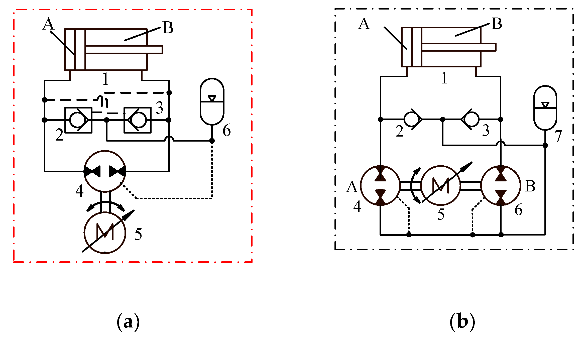
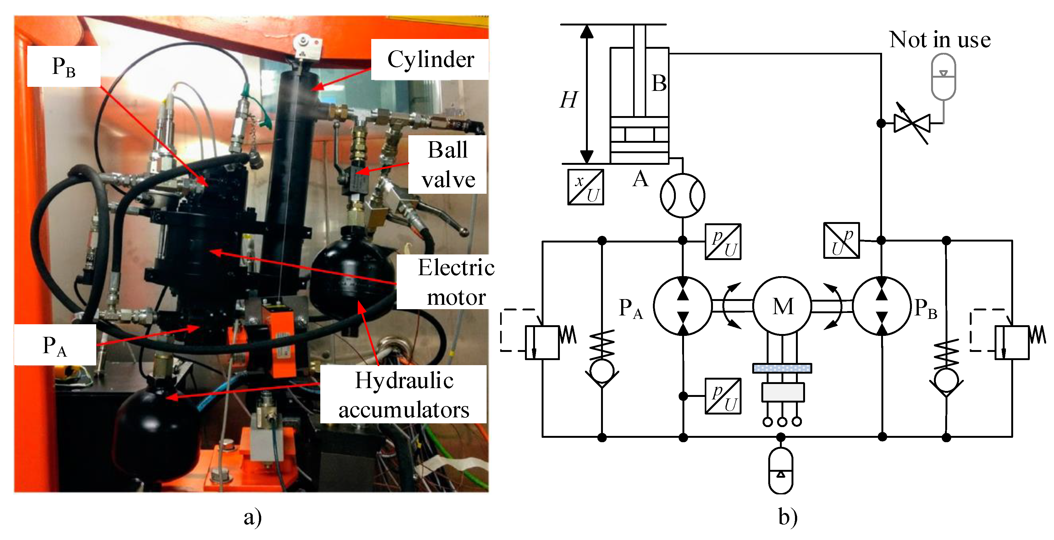
As shown in Figure 1a, the single pump-controlled cylinder (SPC) comprises a pump driven by a permanent magnet servo motor (PMSM) (5), a couple of pilot-operated check valves (2 and 3) for compensating the differential flow of the single rod cylinder and a low-pressure hydraulic accumulator (6) instead of a reservoir.
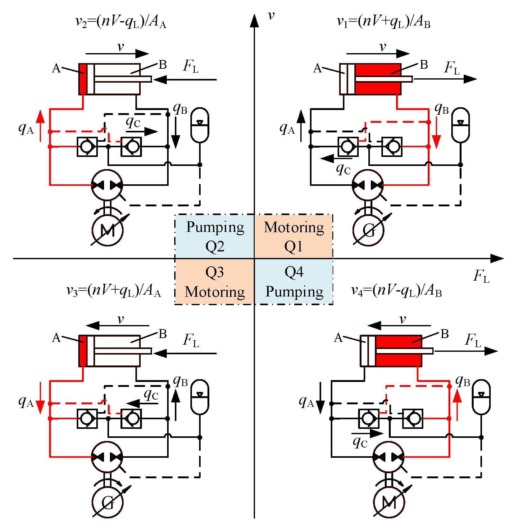
The operating condition of the SPC can be divided into four quadrants, as shown in Figure 2, based on the directions of the actuator’s load force and velocity. This can be classified into two groups: one group outputting power to the load and another feeding back power from the load. In quadrant 1 (Q1) and quadrant 3 (Q3), the pump runs in motoring mode and the electric motor runs in generating mode. In quadrant 2 (Q2) and quadrant 2 (Q4), the pump operates in pumping mode and the electric motor runs in motoring mode. The differential flows of the asymmetric cylinder are compensated by the flow through the pilot-operated check valve connecting to the low-pressure chamber of the cylinder. Assuming the leakage of the pump/motor qL is constant, the velocity of each quadrant can be illustrated as follows:
v1 = (nV + qL,M)/AB = (nV/ηV,M)/AB,
v2 = (nVqL,P)/AA = (nV·ηV,P)/AA,
v3 = (nV + qL,M)/AA = (nV/ηV,M)/AA,
v4 = (nVqL,P)/AB = (nV·ηV,P)/AB,
where vi (i = 1, 2, 3, 4) denotes the cylinder velocity under the corresponding operating quadrant. V and ηV,P/ηV,M are the displacement and volumetric efficiency of the pump/motor. AA and AB are the effective cross-sectional area of piston and rod side of the cylinder.
In Q1 (motoring mode), the pump acts as a motor and the extending velocity depends on the flowrate discharging from chamber B. Therefore, the extending velocity of the cylinder is regulated by the flowrate qB, decided by the theoretical flowrate of the hydraulic motor plus the leakage.
The variables rV12 and rV43 denote the ratios of the velocity fluctuation when switching from Q1 to Q2 (pumping mode) in the extending phase and from Q4 (pumping mode) to Q3 (motoring mode) in the retracting phase, respectively:
r V 12 = v 1 v 2 1 = n V η v , M A B A A n V η v , P 1 = 1 η v 2 r cyl 1 ,
r V 43 = v 4 v 3 1 = n V η v , P A B η v , M A A n V 1 = η v 2 r cyl 1 ,
r cyl = A B A A ,
η v , M = η v , P = η v .
where it is assumed that the pump and motor volumetric efficiencies (ηV,M and ηV,P) are identical.
Since the velocity fluctuation during operating condition switching would degrade the velocity tracking performance significantly, the DPC is proposed, as shown in Figure 1b. The system compensates the differential flow of the asymmetric cylinder by an additional pump B. In addition, two check valves are installed for anti-cavitation purposes.
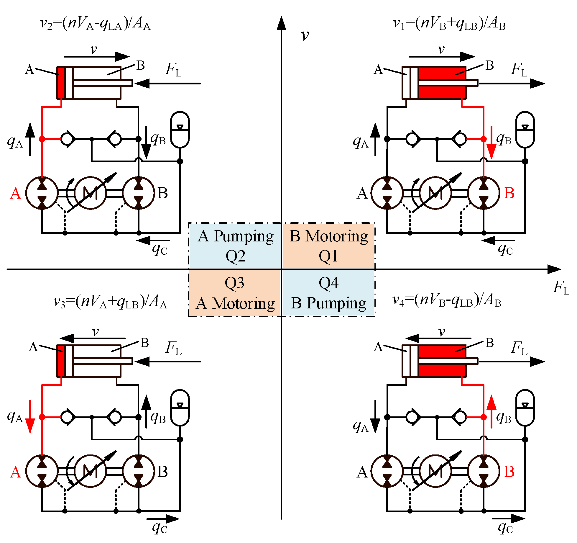
The operating condition of the double pump-controlled system can be divided into four quadrants as well, as shown in Figure 3, including Q1 and Q3 (motoring mode) and Q2 and Q4 (pumping mode). The cylinder velocities in each quadrant are expressed based on the control chamber:
v1 = (nVB + qL,M)/AB = (nVB/ηV,M)/AB,
v2 = (nVAqL,,P)/AA = (nVA·ηV,P)/AA,
v3 = (nVA + qL,M)/AA = (nVA/ηV,M)/AA,
v4 = (nVBqL,P)/AB = (nVB·ηV,P)/AB.
Therefore, the velocity fluctuation ratio rV21 and rV43 are illustrated as follows, respectively.
r V 12 = v 1 v 2 1 = n V B η v , M A B A A n V A η v , P 1 = 1 η v 2 r pu r cyl 1 ,
r V 43 = v 4 v 3 1 = n V B η v , P A B η v , M A A n V A 1 = η v 2 r pu r cyl 1 ,
r pu = V B V A ,
where the rpu is the ratio of displacements of pump/motor A and B.
The displacement ratio rpu of pump/motors and the area ratio of cylinder chambers should be as close as possible, but due to the pump/motors available on the market, the sizing deviation rdev is usually unavoidable. The rdev can be expressed by Equation (16); therefore, rV21 and rV43 can be rewritten as follows, varying with ηV and rdev:
r dev = r pu r cyl 1 .
r V 12 = 1 η v 2 ( 1 + r dev ) 1 ,
r V 43 = η v 2 ( 1 + r dev ) 1 ,
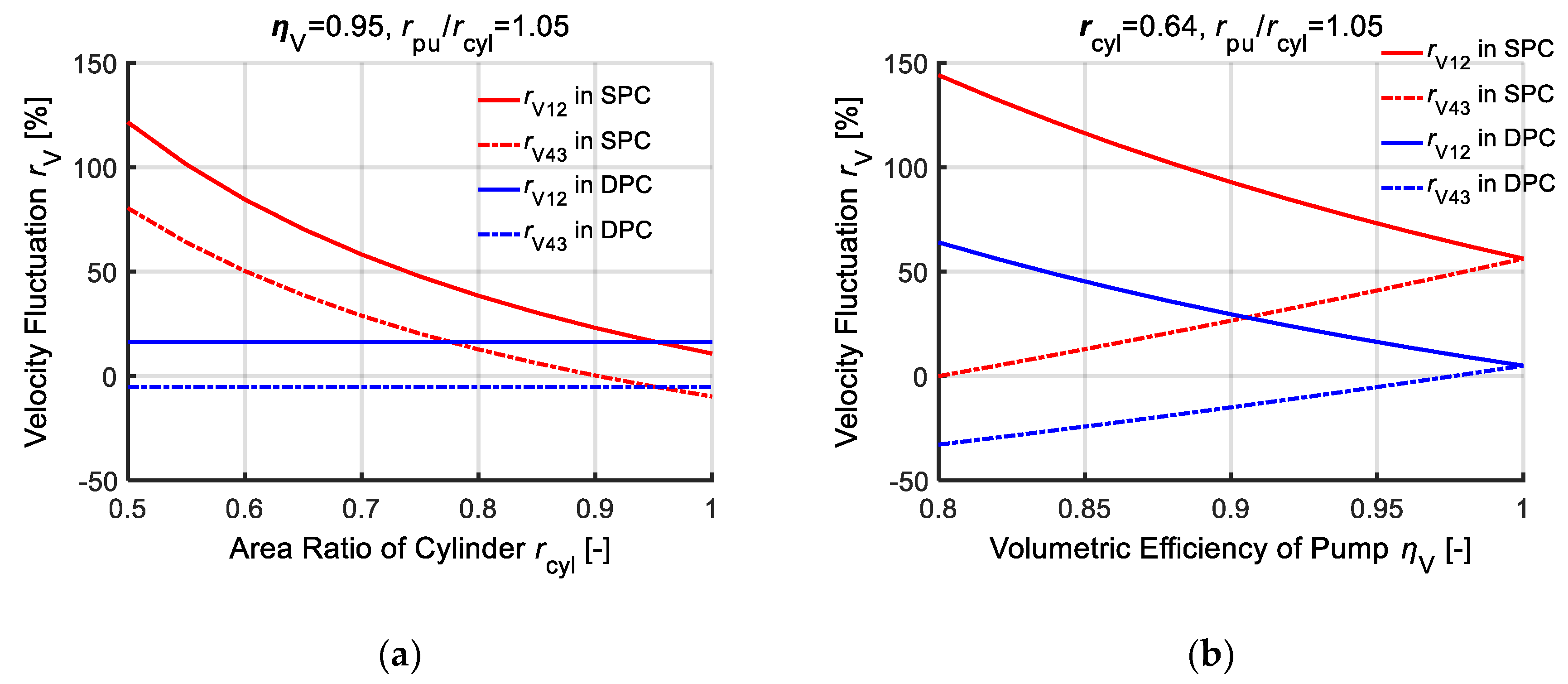
Assuming that the pump volumetric efficiencies (ηV) range from 0.8 to 1, the ratio rcyl (of working area AB to AA of the cylinder) is in the 0.5~1 range. In addition, the sizing deviation of the DPC is assumed to be 0.05, and thus rpu/rcyl = 1.05. Based on these assumptions, the velocity fluctuation percentages of the SPC and the DPC from Q1 to Q2 and from Q4 to Q3 are shown in Figure 4a,b.
It can be seen from Figure 4 that, in the SPC, the velocity would fluctuate heavily when the direction of the force changes during extending or retracting, namely, the operating conditions switch between Q1 and Q2 or Q3 and Q4. Besides, the fluctuation ratios rV21 and rV43 increase as ηV and rcyl decrease.
The results in Figure 4a reveal that, compared to the SPC, the velocity fluctuation in the DPC drops dramatically, especially when rcyl is close to 0.5. The results in Figure 4b show that the velocity fluctuation in the DPC approaches 5% when ηV is close to 1, but 56.25% for the SPC.
In the SPC, assuming ηV = 0.95 and rcyl = 0.64 (the area ratio of the arm cylinder of the micro-excavator), rV12 and rV43 are 73.1% and 41.0%, respectively. On the other hand, in the DPC, assuming ηV = 0.95 and rdev = 0.05, rV12 and rV43 are 16.3% and –5.2%, respectively.
Therefore, the DPC has the potential to eliminate the velocity fluctuation of the pump-controlled asymmetric cylinder under four-quadrant operation.

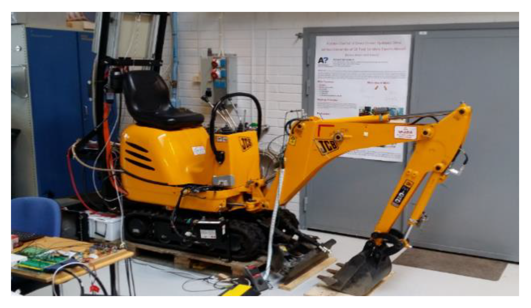
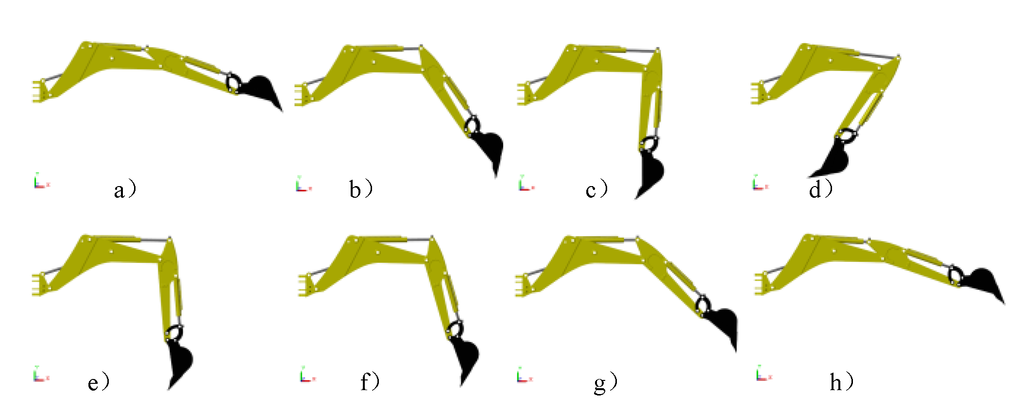
2.2. The Four-Quadrant Operation of the Excavator Arm Cylinder by Measurement

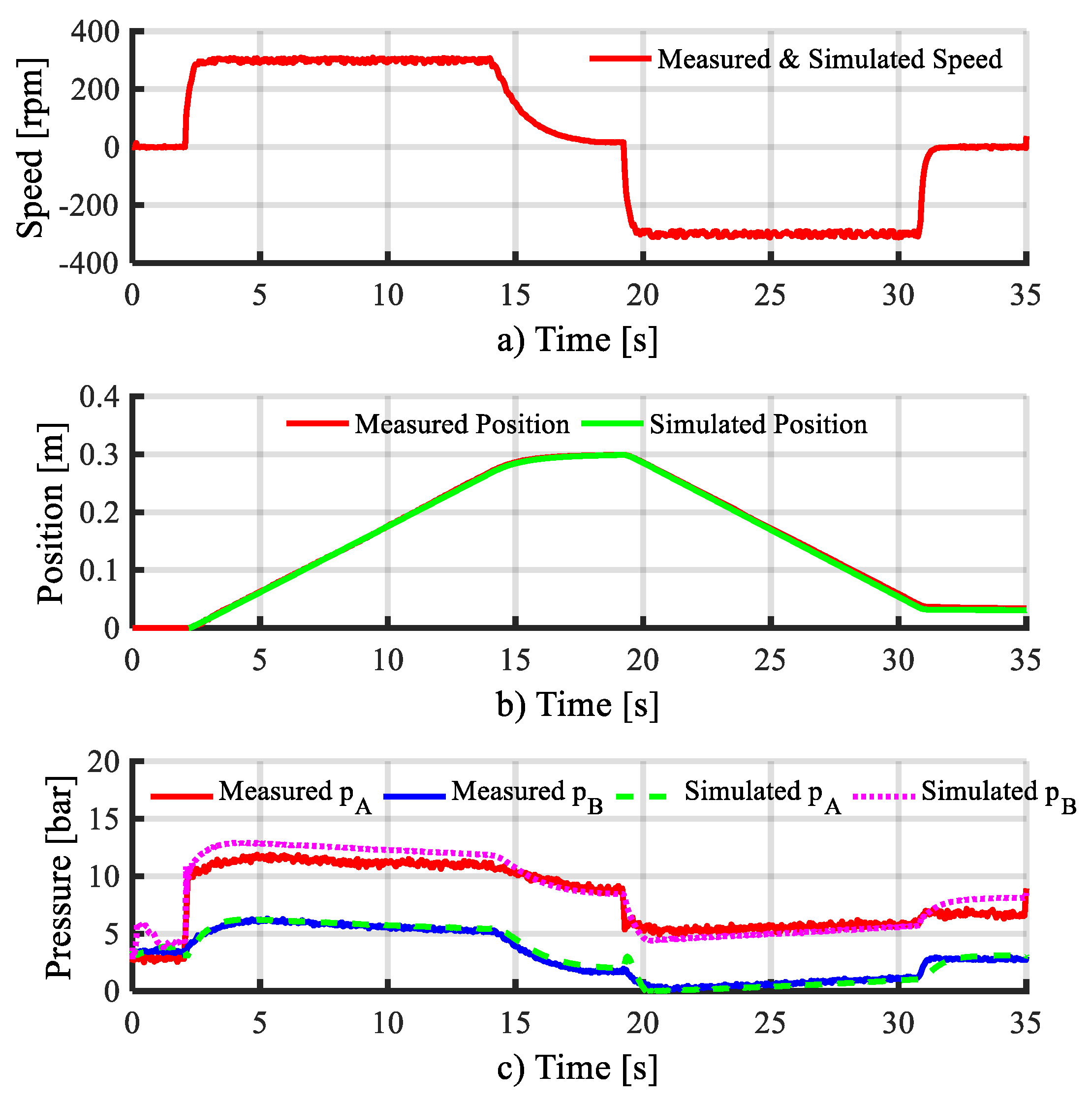
In order to illustrate the four-quadrant operating condition, the necessary measurements of the arm cylinder of the micro-excavator were performed in the laboratory, as shown in Figure 5 [29].
The arm cylinder was controlled to move from a fully retracted position to a fully extracted position and back. Figure 6 presents the calculated load force, measured position and velocity of the arm cylinder. The load force FL of the cylinder was calculated using the measured pressures and the working area of cylinder AA and AB. The velocity was a derivative of the position. It can be seen from Figure 6 that the arm cylinder firstly ran in Q1 (in the stage of a to b with positive load force and velocity) and then switched to Q2 (in the stage of b to c with negative load force and positive velocity) at approximately 7 s when extending. In the phase of c to d, the arm cylinder was fully extended and held. In stage d to e, the arm cylinder retracted and switched from Q4 to Q3 at the d point, and then in Q3 with negative load force and velocity.
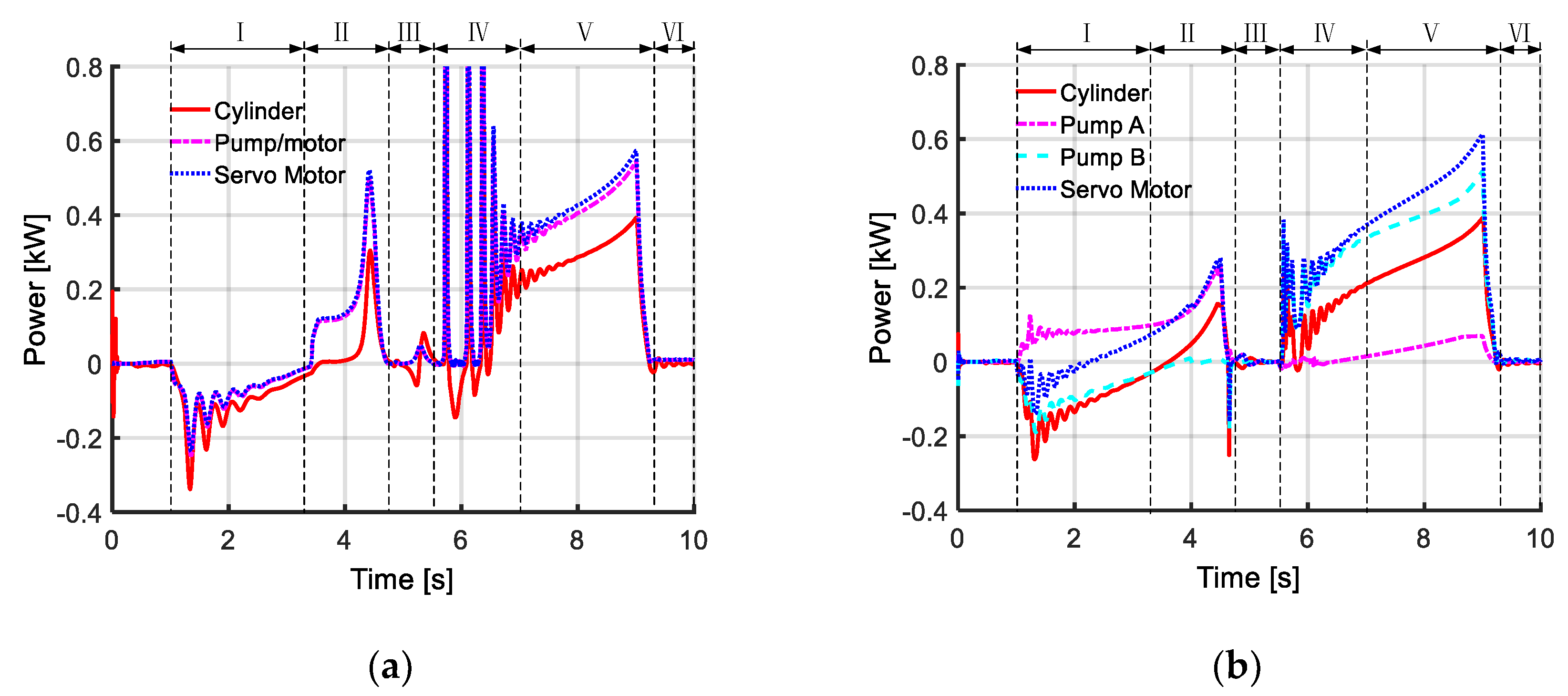
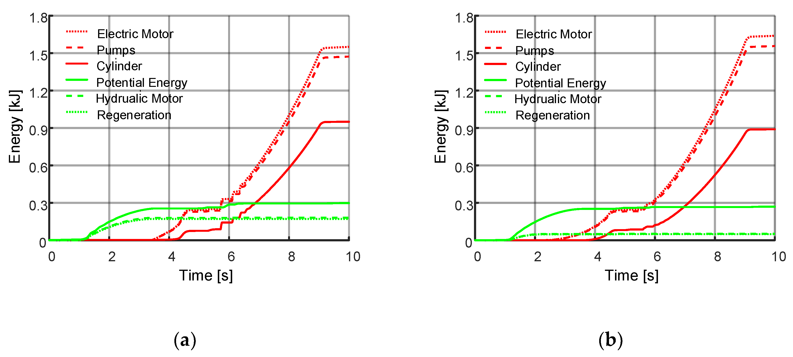
Table 1 compares the components of the SPC and the DPC, including the arm cylinder of the micro-excavator, hydraulic components (four-quadrant external gear motors, check valves, diaphragm accumulator) from Bosh Rexroth and one servo drive. In this study, the dynamics of the servo drive is considered as a second-order system and its energy efficiency is set to be a constant (95%). It can be seen from Table 1 the DPC requires one additional pump 7.1 cm3/rev and the SPC needs two pilot-operated check valves.
To investigate the control performance and energy behavior of the SPC and the DPC under four-quadrant operation, the following section presents details of modeling of the two systems with the front attachment of the excavator.

3. Modeling

The following section introduces the models of the SPC and DPC, including the electric machine (servo motor), mechanical multibody and hydraulic components. Further, those models were built with MATLAB/Simulink.

3.1. Servo Motor

The servo motor dynamics can be represented by a second-order system and is operated with closed-loop speed control [12,30],
ω ¨ m = ω v 2 u m 2 ζ v ω v ω ˙ m ω v 2 ω m ,
where ωm and ωv stand for the speed and bandwidth of the PMSM (ωv = 120π [rad/s]). ζv is the servo drive damping ratio (ζv = 0.7) and um is the motor control input.

3.2. Mechanical Model

To create a mechanical model, the front attachment of the micro-excavator was dissembled, and the dimension, weight and gravity center of each component were measured. The weight distribution of the front attachment components is displayed in Table 2. For details, refer to [31]. Three-dimensional models were built and assembled in PTC Creo based on measured data. Further, the whole model was exported from Creo and imported into MATLAB Simulink. Besides, the mechanical model was verified by experiment in [29].

3.3. Hydraulic Model

As shown in Figure 1a,b, the single and double pump-control circuits mainly consist of pump/motor, cylinder, check valve and hydraulic accumulator. Hence, mathematical models of these components are demonstrated in the following subsections.

3.3.1. Bulk Modulus Model of the Oil

The effective bulk modulus B(p) of the oil in different volumes can be computed by applying Equation (20), where B(p) is determined by the pressure and content of free air in the oil.
B ( p ) = ( ( p 0 p ) 1 N X 0 + 1 X 0 ) 2 X 0 N p ( p 0 p ) 1 N + 1 X 0 B f ,
where Bf is the bulk modulus of the oil, p0 and p are the pressures in the initial state and in the fluid–air mixture, X0 is the relative portion of undissolved air in the oil–air mixture in the initial state and N is the polytrophic index.

3.3.2. Pump/Motor Model

The actual flow rate of the pump/motor is determined by displacement, rotation speed and leakage. It can be expressed by:
q PM = ω PM V PM + q L ( Δ p PM ) ,
where the ωPM is the angular velocity, VPM is the displacement and qL is the overall leakage determined by the pressure difference in pumping and motoring modes.
The overall leakage (including internal and external leakages) can be seen as only dependent on the pressure difference across the pump/motor based on the experiment results.
q L = K HP Δ p PM ,
where KHP is the Hagen–Poiseuille coefficient based on a datasheet from the manufacturer and measured data.
In addition, the friction of the pump/motor Tr is calculated by:
T r = T 0 + K TP | Δ p PM | ,
where KTP is the gain of friction torque vs. pressure difference and T0 is the no-load torque.

3.3.3. Cylinder Model

The internal and external leakages of the cylinders are assumed to be zero, and thus the state equations of the pressures pA and pB in the chambers of the piston and rod side are shown as follows:
p ˙ A = B ( p ) V 0 A + A A x ( q A A A x ˙ ) ,
p ˙ B = B ( p ) V 0 B + A A ( x max x ) ( q B + A B x ˙ ) ,
where B(p) denotes the effective bulk modulus, V0A and V0B denote the wasted volumes in chambers A and B, qA and qB denote the flowrates into the chambers A and B and x is the relative distance between the piston and the cylinder end.
Net force or load force of the cylinder is calculated by the difference of hydraulic force minus friction force:
F hyd = F L = ( p A A A p B A B ) F r .
The friction force Fr was computed by using a LuGre model, which is a widely used dynamic seal model. Additionally, the parameters for the friction model were identified by measurements [29].

3.3.4. Pilot-Operated Check Valve Model

The flowrates passing through the pilot-operated check valve flow paths are computed on the basis of an orifice equation:
q chk = C q A chk x chk 2 ρ Δ p chk sign ( Δ p chk ) ,
where Cd is the discharge coefficient, Achk is flow area of the discharge orifice, Δpchk is the pressure difference over the valve and xchk is the relative opening of the valve. Regarding the pilot-operated check valve, its operation includes normal flow and reverse flow. The relative opening of the valve can be represented by:
x chk = { [ ( p in p out ) A S F S 0 ] / k S [ ( p pilot p in ) A pilot + ( p in p out ) A S F S 0 ] / k S ,
where pin and pout are the inlet and outlet pressures of the check valve, AS and Apilot are the areas of its poppet seat and piloted control spool, ppilot is the pilot pressure, kS is the spring stiffness and FS0 is the spring’s preload force.
Additionally, the poppet dynamics of all the check valves is described with a first-order system with a time constant of 1 ms.

3.3.5. Hydraulic Accumulator Model

A diaphragm hydraulic accumulator is utilized as a low-pressurized reservoir to charge and discharge the unbalanced flow during the retracting and extending phases of the asymmetric cylinder. Hence, it is modeled with a reversible adiabatic process:
p 0 , a = p a V a N / V 0 , a N + p HS ,
where V0,a and Va are the initial gas volume and the current gas volume and p0,a, pa and pHS denote the pre-charge pressure, the fluid pressure and the hard-stop contact pressure, respectively.

3.3.6. Definition of Power Distribution, Energy Consumption and Efficiency

In this subsection, the power distribution, energy computation and efficiency of the cylinder, pump/motor and electric machine are illustrated as follows.
The input power of the cylinder is the product of its net force and velocity, as expressed by:
P Cyl = ( p A A A p B A B ) x ˙ .
For the pump/motor, the input power of the pump and output power of the motor are listed as follows:
P PM = { ω PM ( V PM Δ p PM + T r ) Pumping   mode ω PM ( V PM Δ p PM T r ) Motoring   mode .
Assuming that the efficiency of the electric machine is 95%, its input and output powers in generating and motoring modes are demonstrated as follows:
P EM = { ( P PM , A + P PM , B ) / 0.95 P PM , A + P PM , B > 0 Generating     mode ( P PM , A + P PM , B ) 0.95 P PM , A + P PM , B < 0 Motoring     mode .
Further, the energies consumed or fed back by the cylinder, pump/motor and electric machine are the integration of their corresponding powers. When the power is positive, the component is consuming energy and vice versa.
The system efficiency is the ratio of input energy of the cylinder to that of the electric machine. The recovery efficiency is the ratio of output energy of the electric machine to feed back the energy of the cylinder.

3.4. Closed-Loop Position Control with Feedforward Plus Proportional-Integral-Derivative

This subsection illustrates the position control method of the SPC and DPC. To avoid unnecessary oscillations, the transient process of the position signal is arranged by using Han’s tracking differentiator (TD), constructing a transient profile that the output of the plant can reasonably follow [32]. As the dynamic response of the pump-controlled system degraded dramatically compared with the valve-controlled system, the proposed control method combines the pump speed feedforward and proportional-integral-derivative (PID) controller to achieve the desired position tracking performance. The schematics of the controllers for the SPC and DPC are presented in Figure 7a,b.
In Figure 7a, the running quadrant is detected with a quadrant detector, and thus the gain of feedforward is auto-switched based on the four-quadrant operating principle of the SPC. As a result, in Q2 and Q3, the PID parameters of the two controllers were equivalent, but, in Q1 and Q4, the parameters were tuned differently.
Table 3 presents the gains in the speed feedforward modules of the two controllers, including: uQ23 in Quadrants 2 and 3, uQ14 in Quadrants 1 and 4 and the ratio of uQ23 to uQ14. Without considering the system leakage and compression of the fluid, the rotating speed of the servo motor is proportional to the effective area over the velocity of the cylinder, as shown in Table 3.

3.5. Partial Model Validation

In Figure 8a,b, a DPC unit was installed on a crane and an experiment was performed to validate the built DPC model [15]. The schematics contains two accumulators, however, only one was used during the experimental study. The hydraulic accumulator mounted on the rod side of the cylinder was closed with a ball valve during the experiment, as indicated in Figure 9b. The cylinder of the crane is 60/30 × 400 mm, and the mass load is 40 kg.
In order to validate the DPC model, a mechanical model of the crane was created in MATLAB/Simulink as well. Further, the DPC model and the mechanical model were combined into one complete model. After that, the measured speed of the electric machine, as shown in Figure 9a, was used as input to the DPC installed on the crane and the DPC in the completed model with open-loop control. It can be seen that the input speeds to the test bench and the DPC model are identical. Figure 9b presents the simulated position and measured position, where the cylinder extends and then retracts. From the comparison of these two results, only slight errors at the beginning (in 0~2.5 s) and end (around 30 s) can be seen. Figure 9c compares the pressure levels in chambers A and B. A comparison of the two results reveals that the simulated pressures match the measured one well, although the pressure in chamber A shows some errors in the extending stage and the holding stage. Hence, the developed model has acceptable accuracy and can be used to evaluate the performance of the arm DPC.

4. Results and Analysis

This section presents the simulations of the SPC and the DPC with the proposed position control method under the four-quadrant operation of the arm cylinder. Figure 10 demonstrates the visualization of the controlled motion in the simulation, including Figure 10a the initial position of arm cylinder, Figure 10b,c the extending phase, Figure 10d the fully extended position, Figure 10e,f,g the retracting phase of the arm cylinder, and Figure 10h the fully retracted position. The arm cylinder was controlled to move from the fully retracted position to the fully extended position from Figure 10a–d, and back from Figure 10e–h.

4.1. Position Tracking Performance and Velocity Fluctuation Analysis

In this subsection, the position tracking performance and velocity fluctuation are compared for the SPC and the DPC, as shown in Figure 11a,b. Additionally, the process was divided into six phases (including phase I~phase VI, as shown in Figure 11). Table 4 presents the maximum velocity error and position tracking error of the SPC and the DPC in each phase.
In phase I (1.0~3.3 s), the arm is extending and moving from Figure 10a–c. The cylinder extends in Q1 (positive velocity and positive load force) and, thus, the rod side of the cylinder is the control chamber. The position curves of the SPC and DPC almost overlap, but the velocity oscillation of the SPC is much stronger. The maximum velocity error of the SPC (24.2%) is nearly twice as much as that of the DPC (12.5%).
In phase II (3.3~4.73 s), the arm is extending and moving from Figure 10c,d. The control chamber switches from the rod side to the cap side of the cylinder and the operating quadrant switches from Q1 to Q2 (positive velocity and negative load force). Therefore, the control chamber switches frequently, causing the velocity fluctuation. It can be seen that the SPC system fluctuates much more. For instance, the velocity errors of the SPC are 32.1% and 36.1% at the b point (4.23 s) and the c point (4.50 s), respectively, as shown in Figure 11a, but these values are 5.1% and 0.8% for the DPC, respectively.
In phase III (4.73~5.5 s), the cylinder is fully extended and braked, as shown in Figure 10d and, thus, the load force goes down, and the damping of the system drops dramatically. Hence, the velocity overshoots and the oscillations of the two systems are both noticeable. The maximum position errors of the SPC and DPC are 13.1 mm and 5.0 mm, respectively.
In phase IV (5.5~6.93 s), the working situation is the reverse process of phase II, and the arm moves from Figure 10d,e. Due to the switching of the operating quadrant, the velocities of the two systems fluctuate dramatically. The maximum velocity errors of the SPC and DPC are 74.4% and 34.5%, respectively. The maximum position errors of the SPC and DPC are 10.7 mm and 2.3 mm, respectively.
In phase V (6.93~9.2 s), the arm is moving from Figure 10f–h. The velocities of the two systems stabilize, and the maximum position errors of the SPC and DPC are 4.8 mm and 2.7 mm, respectively.
In phase VI (9.2~10.0 s), the arm is fully retracted and held, as displayed in Figure 10h. The velocity oscillates mildly, and the position error is around 2.0 mm.
Based on the above results, it can be seen that the DPC can eliminate the velocity fluctuation and track the position reference much better.

4.2. Energy Consumption, Efficiency and Regeneration Analysis

Figure 12a,b illustrate the power consumption and regeneration of the SPC and DPC, including the cylinder, pump/motor and electric machine.
In phase I (1.0~3.3 s), the pump/motor of the SPC operates in motoring mode and the servo motor operates in generating mode because of the energy fed back from the lowering arm under Q1. For the DPC, pump/motor A runs in pumping mode throughout the phase. However, the servo motor runs in generating mode only from 1.0 to 2.0 s and then switches to motoring mode (in Figure 12b) because of the energy losses of the added pump/motor (including leakage and friction). Hence, it can be seen from Figure 13a,b that the regenerated energy of the DPC decreases significantly.
In phase II (3.3~4.73 s), to extend the arm from Figure 10c,d, the servo motors output energy to the pump/motor of the SPC and pump/motor A of the DPC respectively. However, pump/motor B in DPC stays idle.
In phase IV, the changes in load direction and velocity direction cause the velocity to fluctuate and the output power strike of the electric machine.
In phase V (6.93~9.2 s), the power required by the DPC is relatively higher because of the leakage and friction loss of the added pump/motor.

5. Discussion

This study investigates a double pump variable speed controlled asymmetric cylinder (DPC) and its control method under four-quadrant operating conditions. A comparison between a single pump variable speed controlled asymmetric cylinder (SPC), and the proposed system was done based on a MATLAB/Simulink model. The two systems were modeled and coupled with the multibody dynamics of the front attachment of a micro-excavator and utilized a four-quadrant operating arm as the load. The hydraulic system model of the DPC is considered to be acceptably accurate for further study, as it was validated with experiments done using a crane with a standalone DPC.
In the model, the SPC and DPC units were considered to be mounted on the boom and, thus, the effects of different weights on the energy efficiency and control were not investigated. The leakage model and friction loss model of the pump/motors only consider the factor of pressure difference but not the angular velocity and temperature variation. The efficiency of the electric machine and its drive was set to be 95% both in generating and motoring modes, which should be replaced with an efficiency model coupled with both torque and rotating speed in the next phase of the study.
The velocity fluctuation and position tracking performances of the two systems were shown and analyzed. Additionally, energy consumption and efficiency behaviors were determined and compared.
Table 5 presents the energy consumption and regeneration of the two systems. The fed back energies (0.90 kJ and 0.89 kJ) of the cylinder of the SPC and DPC are basically equivalent to each other, but the regenerated energy (0.17 kJ) of the SPC is much higher compared to the DPC (0.05 kJ), owing to the energy consumed by the additional pump/motor of DPC. Without considering the regeneration, the energy efficiencies of the SPC and DPC are 57.3% and 54.3% respectively.
Table 6 shows the root mean square (RMS) errors and maximum (Max) errors of the velocity and position. Compared to the SPC, the RMS velocity error and RMS position error of the DPC decrease by 54.8% and 61.0%. Furthermore, the maximum velocity error and position error are reduced by 48.3% and 72.7%. Hence, the velocity fluctuation is eliminated, and control accuracy increases by using the DPC instead of the SPC under four-quadrant operation. The control performance of the DPC is better than that of the SPC.
Under the four-quadrant operating condition, the two systems output equivalent energy (0.9 kJ) to the load, but the energy efficiency of the DPC is slightly reduced. Without considering the energy regeneration, the energy efficiency of the SPC is 3% higher than that of the DPC. The energy regeneration efficiencies of the SPC and DPC are 56.7% and 18.5% due to the leakage and friction loss of the added pump/motor.
Furthermore, based on this study, SPC and DPC units can be applied to the front attachment (boom, arm and bucket) of an excavator according to the corresponding operating condition. For example, the boom and bucket adopt the SPC and the arm uses the DPC. With this proposed hybrid pump-controlled system for an excavator, the energy efficiency and control performance will be investigated and compared in future work.

6. Conclusions

This paper proposes a double pump-controlled asymmetric cylinder (driven by a variable speed electric machine) and its control method. The model of the SPC and DPC are constructed with a four-quadrant operating condition, including dynamics of the electric machine, hydraulic model, position control method and multibody model. Experiments of a crane equipped with a DPC were carried out to partially validate the hydraulic model. Further, simulations using the validated models were performed to investigate the position tracking and velocity fluctuation of the two systems. The results indicate that the system efficiency decreases slightly, without considering energy regeneration, by adopting the DPC instead of the SPC, but the position tracking performance improves significantly, and the velocity fluctuation drops dramatically when utilizing the DPC. Therefore, the proposed DPC and its control method can balance the unequal flow of an asymmetric cylinder, eliminate the velocity fluctuation and regenerate the mechanical energy fed back by the load under four-quadrant operation.

Author Contributions

Conceptualization, S.Z., S.L. and T.M.; methodology, S.Z. and S.L.; software, S.Z. and T.M.; validation, T.M. and S.Z.; investigation, S.Z. and S.L.; resources, T.M.; writing—original draft preparation, S.Z. and S.L.; writing—review and editing, T.M.; supervision, T.M.; project administration, T.M.; funding acquisition, T.M. All authors have read and agreed to the published version of the manuscript.

Funding

This work was enabled by the financial support of Business Finland (project and EZE) and internal funding from the Department of Automation Technology and Mechanical Engineering, IHA group at Tampere University, Finland. Additionally, the work was supported by the Scientific Research Fund (No. GY-Z15096) of Fujian University of Technology, the Science Foundation for Young Scholars of Fujian Province (No. 2018J05099), Fujian Key Laboratory of Automotive Electronics and Electric Drive (Fujian University of Technology) and Fujian Public Service Platform for Technical Innovation of Machine Tool Industry.

Acknowledgments

Special thanks to Thales Agostini (Federal University of Santa Catarina, Florianópolis, Brazil) for providing experimental data utilized for model validation.

Conflicts of Interest

The authors declare no conflict of interest.

Abbreviations

SPCSingle pump-controlled asymmetric cylinder
DPCDouble pump-controlled asymmetric cylinder
PMSMPermanent magnet servo motor
Q1Quadrant 1
Q2Quadrant 2
Q3Quadrant 3
Q4Quadrant 4
PIDProportional-integral-derivative
TDTracking differentiator
RMSRoot mean square
MaxMaximum

References

  1. Quan, Z.; Quan, L.; Zhang, J. Review of energy efficient direct pump controlled cylinder electro-hydraulic technology. Renew. Sustain. Energy Rev. 2014, 35, 336–346. [Google Scholar] [CrossRef]
  2. Fu, S.; Wang, L.; Lin, T. Control of electric drive powertrain based on variable speed control in construction machinery. Autom. Constr. 2020, 119, 103281. [Google Scholar] [CrossRef]
  3. Lin, T.; Lin, Y.; Ren, H.; Chen, H.; Chen, Q.; Li, Z. Development and key technologies of pure electric construction machinery. Renew. Sustain. Energy Rev. 2020, 132, 110080. [Google Scholar] [CrossRef]
  4. Sprockhoff, V. Research on the System Performance of Servo Pump Controlled Cylinder. Ph.D. Thesis, RWTH Aachen, Aachen, Germany, 1979. [Google Scholar]
  5. Kazmeier, B. Energy Efficient Control of a Small Power Electro Hydraulic Linear Drive with Speed Variable Electric Motor and Displacement Variable Pump. Ph.D. Thesis, TUHH, Hamburg, Germany, 1998. [Google Scholar]
  6. Ketelsen, S.; Padovani, D.; Andersen, T.O.; Ebbesen, M.K.; Schmidt, L. Classification and review of pump-controlled differential cylinder drives. Energies 2019, 12, 1293. [Google Scholar] [CrossRef] [Green Version]
  7. Schmidt, L.; Ketelsen, S.; Brask, M.H.; Mortensen, K.A. A class of energy efficient self-contained electro-hydraulic drives with self-locking capability. Energies 2019, 12, 1866. [Google Scholar] [CrossRef] [Green Version]
  8. Lodewyks, J. Differential Cylinder Control in the Hydrostatic Transmission. Ph.D. Thesis, RWTH Aachen, Aachen, Germany, 1994. [Google Scholar]
  9. Quan, L.; Neubert, T.; Helduser, S. Principle to closed loop control differential cylinder with double speed variable pumps and single loop control signal. Chin. J. Mech. Eng. 2004, 17, 85–88. [Google Scholar] [CrossRef]
  10. Kilic, E.; Dolen, M.; Caliskan, H.; Bugra Koku, A.; Balkan, T. Pressure prediction on a variable-speed pump controlled hydraulic system using structured recurrent neural networks. Control. Eng. Pr. 2014, 26, 51–71. [Google Scholar] [CrossRef]
  11. Pedersen, H.C.; Schmidt, L.; Andersen, T.O.; Brask, M.H. Investigation of new servo drive concept utilizing two fixed displacement units. JFPS Int. J. Fluid Power Syst. 2015, 8, 1–9. [Google Scholar] [CrossRef] [Green Version]
  12. Schmidt, L.; Roemer, D.B.; Pedersen, H.C.; Andersen, T.O. Speed-Variable Switched Differential Pump System for Direct Operation of Hydraulic Cylinders. In Proceedings of the ASME/BATH 2015 Symposium on Fluid Power and Motion Control, Chicago, IL, USA, 12–14 October 2015; p. V001T01A042. [Google Scholar]
  13. Schmidt, L.; Groenkjaer, M.; Pedersen, H.C.; Andersen, T.O. Position Control of an Over-Actuated Direct Hydraulic Cylinder Drive. Control. Eng. Pr. 2017, 64, 1–14. [Google Scholar] [CrossRef]
  14. Ketelsen, S.; Schmidt, L.; Donkov, V.H.; Andersen, T.O. Energy Saving Potential in Knuckle Boom Cranes using a Novel Pump Controlled Cylinder Drive. Model. Identif. Control. A Nor. Res. Bull. 2018, 39, 73–89. [Google Scholar] [CrossRef] [Green Version]
  15. Agostini, T.; De Negri, V.; Minav, T.; Pietola, M. Effect of Energy Recovery on Efficiency in Electro-Hydrostatic Closed System for Differential Actuator. Actuators 2020, 9, 12. [Google Scholar] [CrossRef] [Green Version]
  16. Minav, T.A.; Bonato, C.; Sainio, P.; Pietola, M. Efficiency of direct driven hydraulic drive for non-road mobile working machines. In Proceedings of the International Conference on Electrical Machines, Berlin, Germany, 2–5 September 2014; pp. 2431–2435. [Google Scholar]
  17. Danaee, S.; Nurmi, J.; Minav, T.; Mattila, J.; Pietola, M. Direct Position Control of Electro-Hydraulic Excavator. In Proceedings of the BATH/ASME 2018 Symposium on Fluid Power and Motion Control 2018, Bath, UK, 12–14 September 2018; p. V001T01A049. [Google Scholar]
  18. Casoli, P.; Scolari, F.; Minav, T.; Rundo, M. Comparative Energy Analysis of a Load Sensing System and a Zonal Hydraulics for a 9-Tonne Excavator. Actuators 2020, 9, 39. [Google Scholar] [CrossRef]
  19. Zhang, S.; Minav, T.; Pietola, M.; Kauranne, H.; Kajaste, J. The effects of control methods on energy efficiency and position tracking of an electro-hydraulic excavator equipped with zonal hydraulics. Autom. Constr. 2019, 100, 129–144. [Google Scholar] [CrossRef]
  20. Turunen, A.; Minav, T.A.; Hanninen, H.; Pietola, M. Experimental Investigation of Direct Drive Hydraulic Units Implemented in A Mining Loader. In Proceedings of the 2018 Global Fluid Power Society PhD Symposium (GFPS), Samara, Russia, 18–20 July 2018; pp. 1–6. [Google Scholar]
  21. Minav, T.; Lehmuspelto, T.; Sainio, P.; Pietola, M. Series Hybrid Mining Loader with Zonal Hydraulics. In Proceedings of the 10th International Fluid Power Conference, Dresden, Germany, 8–10 March 2016. [Google Scholar]
  22. Imam, A.; Rafiq, M.; Jalayeri, E.; Sepehri, N. A Pump-Controlled Circuit for Single-Rod Cylinders that Incorporates Limited Throttling Compensating Valves. Actuators 2018, 7, 13. [Google Scholar] [CrossRef] [Green Version]
  23. Rahmfeld, R.; Ivantysynova, M. Displacement controlled linear actuator with differential cylinder—A way to save primary energy in mobile machines. In Proceedings of the Fifth International Conference on Fluid Power Transmission and Control, Hangzhou, China, 3–5 April 2001; pp. 316–322. [Google Scholar]
  24. Rahmfeld, R.; Ivantysynova, M.; Weber, J. Displacement controlled wheel loader—A simple and clever solution. In Proceedings of the 4th International Fluid Power Conference, Dresden, Germany, 25–26 March 2004; pp. 183–196. [Google Scholar]
  25. Williamson, C.; Zimmerman, J.; Ivantysynova, M. Efficiency study of an excavator hydraulic system based on displacement-controlled actuators. In Proceedings of the Bath/ASME Symposium on Fluid Power and Motion Control, Bath, UK, 10–12 September 2008; pp. 293–310. [Google Scholar]
  26. Ivantysynova, M. Variable displacement pump will be of great developmental potential. In Proceedings of the 1st International Fluid Power Conference, Aachen, Germany, 17–18 March 1998; pp. 359–371. [Google Scholar]
  27. Gao, Y.; Cheng, J.; Huang, J.; Quan, L. Simulation Analysis and Experiment of Variable-Displacement Asymmetric Axial Piston Pump. Appl. Sci. 2017, 7, 328. [Google Scholar] [CrossRef] [Green Version]
  28. Ge, L.; Quan, L.; Li, Y.; Zhang, X.; Yang, J. A novel hydraulic excavator boom driving system with high efficiency and potential energy regeneration capability. Energy Convers. Manag. 2018, 166, 308–317. [Google Scholar] [CrossRef]
  29. Salomaa, V. Efficiency Study of an Electro-Hydraulic Excavator. Master’s Thesis, Tampere University of Technology, Tampere, Finland, 2017. [Google Scholar]
  30. Schmidt, L.; Andersen, T.O.; Pedersen, H.C.; Hansen, A.H. An Energy Efficient Hydraulic Winch Drive Concept Based on a Speed-Variable Switched Differential Pump. In Proceedings of the ASME/BATH 2017 Symposium on Fluid Power and Motion Control, Sarasota, FL, USA, 16–19 October 2017; p. V001T01A034. [Google Scholar]
  31. Niraula, A.; Zhang, S.; Minav, T.; Pietola, M. Effect of Zonal Hydraulics on Energy Consumption and Boom Structure of a Micro-Excavator. Energies 2018, 11, 2088. [Google Scholar] [CrossRef] [Green Version]
  32. Han, J. From PID to Active Disturbance Rejection Control. IEEE Trans. Ind. Electron. 2009, 56, 900–906. [Google Scholar] [CrossRef]
Figure 1. Simplified circuit of the two-pump control system: (a) SPC, (b) DPC.
Actuators 09 00123 g001
Figure 2. Four-quadrant operation of the SPC.
Actuators 09 00123 g002
Figure 3. Four-quadrant operation of the DPC.
Actuators 09 00123 g003
Figure 4. The velocity fluctuation percentages of the SPC and the DPC from Q1 to Q2 and from Q4 to Q3: (a) ηV = 0.95, rpu/rcyl = 1.05 and 0.5 < rcyl < 1, (b) rcyl = 0.64, rpu/rcyl = 1.05 and 0.8 < ηV < 1.
Actuators 09 00123 g004
Figure 5. The micro-excavator in the laboratory.
Actuators 09 00123 g005
Figure 6. Experimental results of detecting the operation conditions of the arm cylinder.
Actuators 09 00123 g006
Figure 7. Schematics of closed-loop position control with speed feedforward plus PID: (a) SPC, (b) DPC.
Actuators 09 00123 g007
Figure 8. DPC installed on a crane for test: (a) picture of the test bench, (b) schematics of the test bench.
Actuators 09 00123 g008
Figure 9. Validation of the DPC model: (a) input speed, (b) cylinder position, (c) pressures in chambers A and B.
Actuators 09 00123 g009
Figure 10. Visualization of the four-quadrant operation of the arm cylinder.
Actuators 09 00123 g010
Figure 11. Tracking performance comparison of the SPC and DPC: (a) position tracking and velocity fluctuation, (b) position tracking error.
Actuators 09 00123 g011
Figure 12. Power consumption and regeneration: (a) SPC, (b) DPC.
Actuators 09 00123 g012
Figure 13. Energy consumption and regeneration: (a) SPC, (b) DPC.
Actuators 09 00123 g013
Table 1. Comparison of the components of the SPC and DPC.
Cylinder (mm)Pump/Motor (cm3/rev)Check ValvesAccumulator (L)Servo Drive
SPC50/30 × 40011.32 (pilot-operated)0.71
DPC7.1 and 11.32
Table 2. The weight distribution of the front attachment.
Structure (kg)Cylinder (kg)Others (kg)Overall (kg)
Boom59.516.04.580.0
Arm28.011.0039.0
Bucket30.09.010.049.0
Table 3. Feedforward gains of four-quadrant operation.
uQ23 in Quadrants 2 and 3uQ14 in Quadrants 1 and 4uQ23/uQ14
SPC60AA/V60AB/VAA/AB
DPC60AA/VA60AB/VB1
Table 4. Maximum velocity error and position tracking error of the SPC and DPC in each phase.
Maximum Velocity Error (mm/s) and Position Tracking Error (mm)
I (1.0~3.3 s)II (3.3~4.73 s)III (4.73~5.5 s)IV (5.5~6.93 s)V (6.93~9.2 s)VI (9.2~10.0 s)
SPC27.71.864.518.364.013.185.310.715.64.88.72.0
DPC14.30.744.14.833.05.039.52.312.82.711.02.5
Table 5. Energy consumption and regeneration of the SPC and DPC.
Electric MotorPumpCylinderPotential EnergyHydraulic MotorsRegeneration
SPC (kJ)1.551.470.900.300.180.17
DPC (kJ)1.641.560.890.270.050.05
Table 6. Comparisons of position tracking and velocity fluctuation between the SPC and DPC.
Velocity Error (mm/s)Position Error (mm)
RMSMaxRMSMax
SPC35.285.35.918.3
DPC15.944.12.35.0
Publisher’s Note: MDPI stays neutral with regard to jurisdictional claims in published maps and institutional affiliations.

