Abstract
This paper proposes the implementation of an assisting technology to a processing/reprocessing mechatronics line (P/RML), comprising the following: two autonomous robotic systems (ARSs), two robotic manipulators (RMs) and three visual servoing systems (VSSs). The P/RML has four line-shaped workstations assisted by two ARSs—wheeled mobile robots (WMRs): one of them equipped with an RM, used for manipulation, and the other one used for transport. Two types of VSSs—eye to hand and eye in hand—are used as actuators for precise positioning of RMs to catch and release the work-piece. The work-piece visits stations successively as it is moved along the line for processing. If the processed piece does not pass the quality test, it is taken from the last stations of the P/RML and it is transported to the first station where it will be considered for reprocessing. The P/RML, assisted by ARSs, RMs and VSSs, was modelled with the synchronized hybrid Petri nets (SHPN). To control the ARSs, we propose the use of trajectory-tracking and sliding-mode control (TTSMC). The precise positioning that allows the picking up and releasing of the work-piece was performed using two types of VSSs. In the case of the first one, termed eye to hand VSS, the cameras have a fixed position, located at the last and the first workstations of the P/RML. For the second one, named eye in hand VSS, the camera is located at the end effector of the RM.
1. Introduction
Central to the idea of the paper is the overall proposed approach: a technology that works on a laboratory system and integrates several systems: processing/reprocessing mechatronics line (P/RML), autonomous robotic systems (ARSs), robotic manipulators (RMs) and visual servoing systems (VSSs). The technology involves several concepts: task planning, hybrid modelling, simulation, sensors, actuators, monitoring and real-time control. The technology allows the recovery of products through reprocessing and works completely automated without the intervention of the human operator. The main elements of originality and contributions are concentrated in the following areas: tasks assignment, planning and synchronization of P/RML assisted by ARSs, RMs and VSSs, hybrid modelling and simulation with synchronized hybrid Petri nets (SHPN), modelling and implementation eye to hand and eye in hand VSS and real-time control, so that the whole system becomes fully automated. Through this article, we extended the degree of automation and efficiency of these production lines by ARSs, RMs and VSSs [1,2,3,4,5].
A flexible manufacturing line represents all workstations and cells, actuators, acquisition equipment, ARSs, RMs, VSSs, transport, storage, monitoring and control systems, all of which are capable of performing tasks for processing operations, in a reconfigurable way that gives reversibility, repeatability and, last but not least, flexibility [4,6,7,8,9,10]. The general structure of a P/RML allows the highlighting of the system’s general functions: the function of automatic processing of parts or subassemblies; the function of automatic storage, transport and handling; the function of automatic control of all the components of the system and of supervision, control and automatic diagnosis—realized with the help of one or more PLCs in different configurations, centralized or distributed; the automatic processing function that is performed within the technological subsystem of the P/RML, comprising of the workstations (cells); the function of automatic storage, transport and handling. The processing/reprocessing (P/R) planning process involves more complex requirements such as geometric relationships, performance measurement and evaluation, resource scheduling, kinematics control, and system planning. P/R plans are operation sequences (drilling, reaming, extrusion, bending, etc.), executed in serial or parallel so that the product meets the quality requirements. To a technology on a P/RML assisted by ARSs, RMs and VSSs, a planning strategy oriented to the characteristics of the system is often more effective than techniques derived from domain-independent methods, [10,11]. If the fully processed product fails the quality test, the task planner provides the best sequence for reprocessing the product, [12,13].
The P/RMLs assisted by ARSs and RMs have hybrid characteristics, consisting of continuous dynamics and discrete events behaviours, [7,8]. Hybrid Petri nets (HPNs) are instruments used to model such complex systems [13,14,15,16,17]. Development of knowledge based on an HPN model integrated with a sequence generation algorithm was successfully applied to the modelling and planning of a flexible process and system at a high level, [18]. In this paper, a synchronized hybrid Petri nets (SHPN) model for technology on a P/RML assisted by ARSs, RMs and VSSs is presented. The aim is to assign the tasks to the P/RML workstations for reprocessing the work-piece that fails the quality test. The reprocessing operations are performed on the same line. The new technology concept of P/R is illustrated in an SHPN model, which complies with both aspects: the discrete approach P/R operations and the continuous approach for the displacement of the ARSs. The P/RML is assisted by two ARSs, two RMs, one of them mounted on an ARS, and three VSSs. The P/RML dynamics are determined by events, supplied by the control sequences of the automatic system, and by interaction with the ARSs, which represents the continuous-time part of the system. The considered system is a hybrid one and requires specialized tools for modelling. The hybrid model is elaborated using the dedicated modelling tool, HPN, described in [15,16,17]. An SHPN model results from the combination of the discrete-event model of the P/RML with the cyclic and continuous-time of the ARSs, [5].
Visual servoing systems are known as flexible and robust actuators used to enhance the accuracy and versatility of a control architecture based on visual feedback, [19]. The task of a servoing system is to control the movement of a robotic manipulator from an initial position to the desired configuration. The task of a VSS is defined in relation to how the robot can interact with the working environment using visual sensors. The visual features extracted from the images acquired using the visual sensor represent the inputs for the control architecture. Selecting visual features is a crucial point in a VSS, as these visual features are relevant to performance and accuracy. The minimum number of visual features used in the control architecture to control the movement of an RM depends on the number of degrees of freedom of the robot. Therefore, it is desirable to have a correlation between the visual features used and the movements of the visual sensor [5,6,7,8,9,19].
The rest of the paper is organised as follows: the description of the P/RML assisted by ARSs, RMs and VSSs with task planning useful preliminary assumptions, for developing SHPN model, are laid out in Section 2; model structure and SHPN model formalism, in generalised and customised forms, is presented in Section 3; simulation results are also presented for the customised SHPN model associated with P/RML, assisted by ARSs; modelling and control of the eye to hand and eye in hand VSS, based of the moment of the images, are presented in Section 4; in Section 5, the implementation and real-time control of the P/RML assisted by two ARSs, two RMs, two eye to hand and one eye in hand VSSs based on the SHPN model and signals from sensors are presented; comments on the robustness to the uncertainties of the proposed technology and the need for the use of VSSs can be found in Section 6; some final remarks can be found in Section 7.
2. P/RML Assisted by ARSs, RMs and VSSs
2.1. Hardware Description
P/RML FESTO MPS-200, shown in Figure 1, is a configurable laboratory mechatronic system, which can be assimilated to a flexible manufacturing line that performs several operations. It is composed of four workstations (cells), each performing different operations. These workstations are controlled by separate Siemens S7 300 PLC and each of them ensures the operations in different stages: buffer, handling, processing and sorting. ARS Pioneer 3-DX is used for the recovery operation which is a WMR with two driving wheels and one free wheel. ARS PeopleBot is used for the transport operation, which is similar to the WMR ARS Pioneer 3-DX. The control of the ARSs is carried out by a specialized application developed and executed on a remote PC that transmits commands via Wi-Fi Link, [20,21].
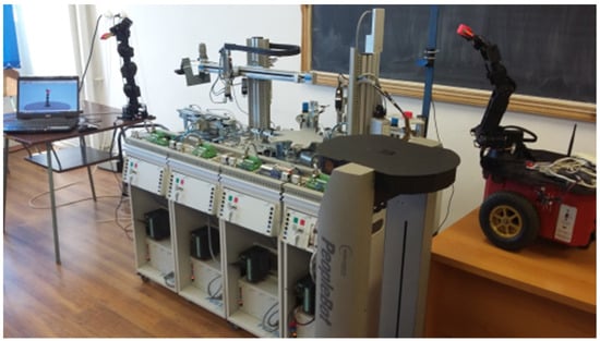
Figure 1.
Processing/reprocessing mechatronics line (P/RML) assisted by autonomous robotic systems (ARSs), robotic manipulators (RMs) and visual servoing systems (VSSs).
On the ARS Pioneer 3-DX, an RM Pioneer 5-DOF (degrees of freedom) is mounted, also controlled via Wi-Fi. For controlling ARSs and RM Pioneer 5-DOF are used dedicated functions from ARIA (Advanced Robotic Interface for Applications) package. In order to return the piece to the line is used 7-DOF manipulator, RM Cyton 1500 connected via USB with the process PC. In the synchronization of the P/RML with the ARSs, RMs are used as signals from sensors and high definition video cameras, two of them integrated as eye to hand and the third as eye in hand VSS. P/RML, ARSs, RMs, cameras and work-pieces are shown in Figure 1 and Figure 2.
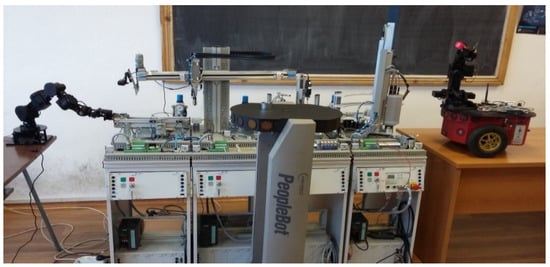
Figure 2.
Work-pieces; ARS Pioneer 3-DX; RM Pioneer 5-Degrees of Freedom (DOF); ARS PeopleBot; RM Cyton 1500.
2.2. Eye to Hand and Eye in Hand VSSs
The eye to hand VSS is defined by the mounting of the video sensor in a fixed position relative to the work environment, [8,9,19]. The eye in hand VSS refers to a system where the video sensor is located to the end effector of the RM, [8,9,19]. For the image-based VSSs, 2D image information is used directly to estimate the desired motion of the robot. Typical tasks such as tracking and positioning are accomplished by minimizing the error between the visual features extracted from the current image and the corresponding visual features of the desired image.
For image-based architectures, the visual sensor used to extract visual information about the work environment can be mounted either directly on the eye-in-hand effector of the robot, in which case the motion of the robot induces and the movement of the camera, or the camera can be mounted somewhere in the workspace (eye-to-hand) so that it can observe the robot’s movement from a fixed point. The general representations of the two architectures are presented in Figure 3. The most commonly used features in object classification and form recognition are the features called moments of the image which, because of their benefits, are also used for robotic and artificial intelligence purposes. Considering an image as a two-dimensional intensity distribution, the moments of the image contain information about the image area, the orientation of the image and the coordinates of the centre of gravity.
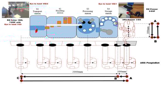
Figure 3.
P/RML assisted by two ARSs, two RMs, two eye to hand VSSs and one eye in hand.
2.3. Task Planning of P/RML
The P/R operations can be broken down into a sequence of elementary tasks coupled in parallel with work-piece positioning tasks along the work station, as in [6,8,12]. The hybrid processing/reprocessing strategy is based on the hierarchical model proposed in [6,7,8,22], which uses a block diagram representation shown in Figure 4. ARSs carry the work-piece that fails the quality test from the place where it is stored (last station of P/RML to the initial position (first station of P/RML) for reprocessing. Figure 4 shows the task planning for processing a work-piece and is transporting by ARSs.
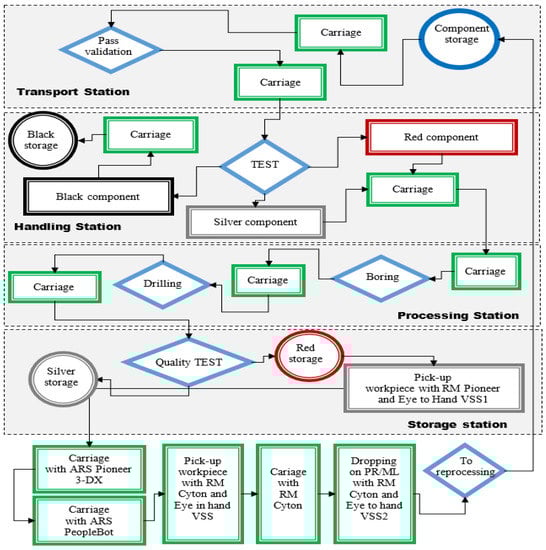
Figure 4.
P/R cycle: transport, handling, drilling, boring, storage, pick-up, dropping.
2.4. Assumptions
Specialized technology on this type of P/RML represents the base of a flexible industrial production line that gives a high range of standard products. Additionally, through reprocessing, the products can be recovered and brought to the required quality standards. The technology on P/RML, further developed, depends on aspects like operation modes, operation lengths and types of finished products [23]. Therefore, for P/RML, ARSs, RMs and VSSs, some assumptions have to be made for controlling the whole system:
Assumption 1.
P/RML is deterministic and with a single SHPN model, that allows the obtaining of suitable quality products and recoverable products, through reprocessing;
Assumption 2.
The number of the P/RML work stations involved in P/R is previously known and will remain unchanged;
Assumption 3.
Only one type of work-piece, but of different colours, is processed or reprocessed, because the proposed technology involves processing operations specific to a certain type of product;
Assumption 4.
All conditions and parameters of the technology are initially known, including task durations, costs and quantity of work-pieces that will take part in the process;
Assumption 5.
The workstations of the P/RML have a linear distribution: transport, handling, processing and storing workstation;
Assumption 6.
The P/R operations are executed on the same line and work-pieces can be processed at the same time in different system stages;
Remark 1.
As a result of the positioning errors or tool misalignments, it is possible for the processing operations not to be carried out properly. If these errors are in the meantime eliminated by performing the operations through reprocessing, the work-piece should be brought to the required quality standard.
Assumption 7.
A red work-piece will mean that the quality test is not passed and reprocessing is needed;
Assumption 8.
In the deposit, the first level from the top is for rejected work-pieces;
Assumption 9.
Two ARSs assisted the P/RML, one of them having mounted an RM, Pioneer 5-DOF, used for picking up the work-piece, and the other used for transport;
Assumption 10.
Two eye to hand VSS cameras are mounted on the P/RML, one on the last and another on the first work station;
Assumption 11.
One eye in hand VSS camera is mounted on the second RM, Cyton 1500.
The use of ARSs is justified for collaborating with the P/RML in order to recover the rejected work-pieces and transport them for reprocessing or for definitive rejection at the beginning of the line. The path and distances that the ARSs should pass are shown in Figure 3.
3. SHPN Model of the P/RML with Integrated ARSs
3.1. Structure of the SHPN Model
The hybrid aspect of the model (P/RML assisted by ARSs) is given by the variables associated with the distances covered by ARSs. These distances are covered by the ARSs between the last workstation (storage workstation) and the first station (transport workstation) of the P/RML. For modelling, we will use the SHPN tool, [12,16], which integrates the discrete aspect of P/RML with the continuous aspect of ARSs displacement likes is shown in [6,7,8,9]. The global model is of the SHPN type because it is interfaced with external events for synchronization, the events being signals coming from sensors and VSSs. The SHPN structure, from Figure 5, corresponds to the discrete modelling of the P/R processes and the continuous dynamics of the ARSs one of them equipped with RM, which assist the P/RML to bring the work-piece from the last to the first workstation, to be reprocessed. The internal structure of the SHPN model integrates two PN models, each of them having a specific typology: TPN (Timed Petri Network) and SPN + TPN (Synchronized Petri Network + Timed Petri Network) and THPN (Timed Hybrid Petri Network), [15,16,17]. These models describe the following operations that are performed automatically: processing (TPN modelling), reprocessing (TPN modelling) and assistance of the ARSs for the work-piece fastening and bringing it for reprocessing. Adding the apparition of an external event, the signals from sensors used for synchronization of the P/RML and the ARSs and RMs, the final model will have an SHPN structure that is shown in Figure 5. Each of the models represents a sequence in the real-time control operation, as follows: TPN type for P/R operations and SPN + TPN type for work-piece retrieving, transport and manipulation.
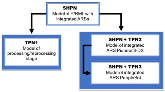
Figure 5.
synchronized hybrid Petri nets (SHPN) structure of P/RML, assisted by two ARSs.
3.2. Formalism of the SHPN Model Associated to P/RML Assisted by Two ARSs
SHPN model from Figure 6, associated with the P/RML assisted by two ARSs is a triplet,
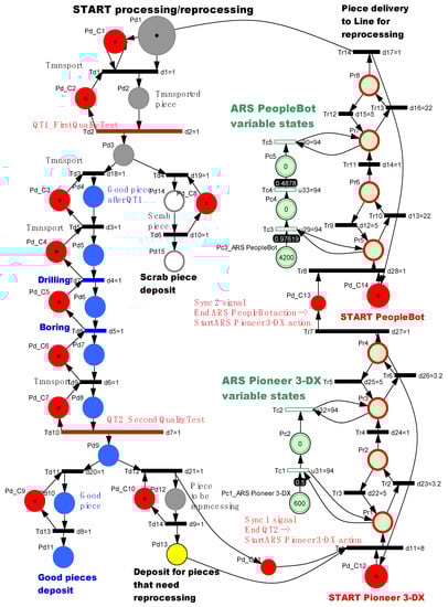
Figure 6.
SHPN model of P/RML assisted by ARSs.
THPN is a septuplet
is a set of external events, signals from sensors.
maps the elements for the set of the discrete transitions in the set of the external events. External events are signals from sensors, used for synchronization.
P is a set of finite places,
where:
with the set of the discrete state corresponding to the processing operations on the P/RML. (buffering, handling, catching, drilling, boring, sorting, releasing, etc.), are the discrete variables of the control system and the discrete states that define the ARSs displacements, with discrete states of the ARS Pioneer 3-DX, while the discrete states of ARS PeopleBot,
with the continuous places of ARS Pioneer 3-DX displacement, while defines the continuous places of the ARS PeopleBot displacement.
is the set of finite transitions
where:
with the set of the discrete transitions for executing work-piece processing, the set of the discrete transitions set of ARS Pioneer 3-DX displacement while returning the work-piece for reprocessing and the set of the discrete transitions of ARS PeopleBot while returning the work-piece for reprocessing,
where: is the set of the continuous transitions of ARS Pioneer 3-DX displacement for transporting the work-piece to the ARS PeopleBot and the set of the continuous transitions of ARS PeopleBot displacement for transporting the work-piece to the RM Cyton. The sets of the places and of the transitions are disjoint .
is the input incidence function;
is the output incidence function;
is the initial marking.
For , and , in the case where , the functions take values in (natural number set) and, in the case where , the functions take values in (positive rational number set).
is a hybrid function
that indicates for every node whether it is a discrete node (sets and ) or a continuous node (sets and ), where and are the sets of the discrete or continuous node, respectively
is the function of the timings associated to the transitions: in Figure 6 and is defined as:
If , then is known as the timing associated with . If then
is the flow rate associated with . For , , where is the variable flow of ARS displacement between continuous places, with .
Let be the ED-enabling degree of a C-transition, , for a marking , denoted as after all the arcs, from a place to a transition, were erased.
Let the maximum firing speed be of transition as the product of its flow rate by its ED- enabling degree. As is shown in Figure 6, will have
where:
is the mark associated with a continuous place and
is the weight of the arc connecting a continuous transition to a continuous place of the ARS.
For the arches have a weight equal to one, where:
For an SHPN, a transition is enabled if each of its input places has enough tokens.
The SHPN model, shown in Figure 6, is an oriented graph described with the Petri Nets (PN) formalism, according to the discrete events system (DES). The SHPN model describes the dynamics of the P/RML assisted by ARSs, as a hybrid process. For making the model, the following assumptions were made:
are the discrete states of the work-piece under processing. The actions that determine the modification of these states correspond to the operations: processing (drilling, boring, etc.), transporting, quality tests (QT1 and QT2) and handling;
are the discrete states of the two ARSs, determined by the running of the fixed point displacement and manipulation;
are the control/synchronization signals necessary for controlling the sequence of tasks and synchronization at the P/RML level, served by ARSs;
are the continuous state variation of the position of the two ARSs, in relation to the endpoint of the displacement, corresponding to a complete service cycle (see Figure 3, with the workstations and the successive positioning scheme of the two ARSs). The synchronization signals are intended for the synchronization of the P/RML, ARS Pioneer 3-DX and ARS PeopleBot actions. In the SHPN formalism, they correspond to the set of events, which in the SHPN model are represented by:
where: , , , , ;
represents the neutral event that is considered to “synchronize” transitions that are neutral in terms of synchronization with other sub-processes;
are the signals injected by changing the states, in the controlled sub-processes, as follows:
synchronization signal for START_P/RML with END_ARS PeopleBot and START_Piece_Delivery to P/RML for reprocessing;
synchronization signal for END_QT2 with START_ARS Pioneer 3-DX actions;
synchronization signal for END_ ARS PeopleBot and START_ARS Pioneer 3-DX actions;
synchronization signal for END_ARS Pioneer 3-DX and START_ARS PeopleBot actions;
synchronization signal for END_Piece_Delivery to P/RML for reprocessing with START_ARS PeopleBot actions;
represents synchronization signals corresponding to each transition in the SHPN model with other sub-processes, so that the SHPN model, implicitly its simulation, is consistent with the control strategy of the whole process:
The paper presented here focuses on the hybrid aspect of the process, both in modelling and in control, taking into account the scenarios of P/RML assistance by ARSs. The hybrid control system of the P/RML serviced by two ARSs, is able to control in real-time the entire process, according to the control strategy.
3.3. Simulation of SHPN Model
Following the testing and simulation of the SHPN model described using the Sirphyco package shown (Figure 6), the simulation results are shown in Figure 7, Figure 8 and Figure 9. The advantage of using common simulation for both the discrete and continuous aspects in the model is that the interaction between the two parts can be obtained and analysed. Additionally, as a result of the hybrid model simulation, the maximum speed of the two ARSs that assist P/RML was reached. The speed was computed so that the cycle time for work-piece recovery and transporting is minimum. In addition, the hardware constraints of the ARSs have to be taken into account in order to obtain the best speed. By using the SHPN model, a unique and precise connection is achieved between the two models: the TPN which models the P/RML tasks and the THPN which models the operations of two ARSs while retrieving and transporting the work-pieces. In the complete SHPN model, represented in Figure 6, each task performed by the P/RML (such as buffering, handling, drilling, boring, etc.) has a very precisely determined time, together with the duration of ARSs displacement. Figure 7 and Figure 8 present simulation results of the model and it can be observed that the time ranges correspond to the given reality.
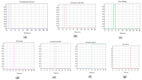
Figure 7.
Discrete place evolution of the work-piece on the P/RML, after the transitions corresponding to the actions: (a) transport; (b) QT1; (c) Drilling; (d) Boring; (e) QT2; (f) Storage; (g) Delivery.
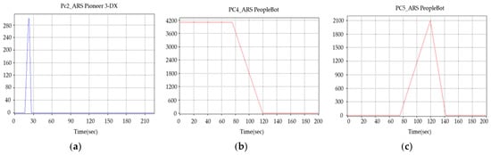
Figure 8.
Continuous places evolution of ARS Pioneer 3-DX and ARS PeopleBot during the transport of the parts: (a) Pc2; (b) Pc4; (c) Pc5.
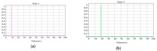
Figure 9.
Synchronisation signals: (a) Sync1; (b) Sync2 (see Figure 6).
Firstly, ARSs are initialised and then the ARS Pioneer 3-DX waits for an external event that is described through the existence of a work-piece that could be reprocessed. The video system used for synchronization detects the appearance of the work-piece and creates this external event which will trigger the robot for retrieving. Next, the ARS Pioneer 3-DX will put the recovered work-piece on the PeopleBot for transporting. Two synchronization signals will be needed:
--synchronization signal End QT2 and START ARS Pioneer 3-DX;
--synchronization with P/RML for reprocessing of the work-piece, END ARS PeopleBot action and START Pioneer 3-DX action.
4. Modelling and Control of the VSSs for Moments of the Image
4.1. Modelling and Control Structure
The structure of a VSS is based on the following components: an autonomous system composed of a mobile robot equipped with a 5 or 6-DOF manipulator, a controller and a video sensor (web camera). The fundamental part of the architecture, the image-based controller requires a priori information about the behaviour of the system in order to minimize the error between a current configuration of visual features, , and a desired configuration, . To model the behaviour in the open loop of the servoing system, the two entities that form the fixed part must be analysed separately: the manipulator robot and the visual sensor. It is still considered a configuration of the eye-in-hand type for the visual sensor-robot assembly. The main idea for modelling a VSS is to minimize the error between the real and desired features extracted from the video sensor, [9,19,23,24]. The control structures of two types of VSSs are shown in Figure 10 and Figure 11. Let be the signal associated to the control input of the ARS. This signal represents the reference speed of the camera and has the following structure: , and defined as the linear and the angular speed, respectively. The signal is expressed in the Cartesian space and requires a transformation to be able to be applied to the manipulator robot. If we note with the posture obtained by integration, then we define the robot Jacobian as:
where represents the state of the robot’s joints. Thus, the signal transformation of from Cartesian space to robot joint space will be achieved by and the interaction matrix. The interaction matrix needs to fulfil a series of properties in order to obtain the optimal behaviour for VSS. It has to be non-singular and diagonal. Considering the moments as a set of visual features then, the analytical form for its variation in time,, corresponding to the moments of order , depending on the speed of the camera , is:
where is the interaction matrix.
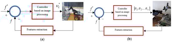
Figure 10.
Eye to hand VSSs based closed-loop control: (a) of ARS Pioneer 3-DX equipped with RM Pioneer 5-DOF for picking up the work-piece with VSS1; (b) of RM Cyton for releasing the work-piece with VSS2, [9]. @2019 IEEE.
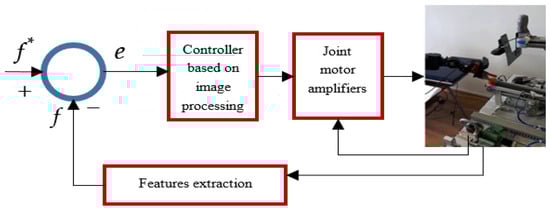
Figure 11.
Eye in hand VSS based closed-loop control of the RM Cyton, [9]. @2019 IEEE.
Based on the theory presented in [9,19,23], the interaction matrix corresponding to a set of moments of the image
, for points, can be computed as below:
4.2. Control Input
The most used method to generate the control signal for robots is the use of proportional control. The visual servoing system can be viewed as a minimization problem that finds the path of the visual sensor by minimizing the cost function attached to the error vector. Note with the desired feature vector, with the current feature vector, and the relative position between the camera and the object at time . Note with
the features variation reported to the relative movement between the workspace and the video sensors:
Because the time variation of the features, reporting to the motion of the object, is zero, then
for a static object. Therefore, (25) becomes
where
is the vector describing the relative speed between the object and the video sensor
and is the interaction matrix from (24). To describing the control law, it is required to define an error function between the target features
and the current features :
Because most implementations of visual servoing systems do not take into account the dynamics of the robot (the dynamics of the robot is considered one), then and (26) becomes:
From (27) and (28) the time variation of the error can be expressed as:
Since the robot control input is defined by and wishing an exponentially negative decrease in the error, , , the following control law is obtained from (29):
where
is the pseudo inverse of the interaction matrix and can be computed with the expression:
Because in real-time VSSs, the distance between the points of interest and the reference system attached to the camera is not precisely known, it must be estimated, noted with . The estimation of this matrix is based on the pseudo-inverse of the target features interaction matrix with . Because this matrix remains constant during the entire control algorithm, the control law is:
5. Real-Time Control of P/RML with Integrated ARSs, RMs and VSSs
To control the assistive technology of the four stations P/RML Festo MPS 200, three robotic systems were integrated: ARS Pioneer 3-DX equipped with RM Pioneer 5-DOF, for picking up the work-piece from the last station; ARS PeopleBot for transporting and RM Cyton 1500 for picking up and releasing the work-piece from ARS PeopleBOT AND on the first work station of P/RML, respectively.
Real-time control of the assisted technology is based on five control loops:
- control loop for P/RML with SIMATIC STEP 7 and SIEMENS 300 PLC;
- control loop for ARS Pioneer 3-DX equipped with RM PIONEER 5-DOF and eye to hand VSS1. Video camera is mounted on the last station of P/RML;
- control loop for ARS PeopleBot based on trajectory tracking sliding-mode control (TTSMC). Additionally, an obstacle avoidance method based on sonars and ultrasounds was implemented [5,9,10];
- control loop for RM Cyton 1500 based on eye in hand VSS for precise positioning for picking up work-piece from ARS PeopleBot. The eye in hand VSS camera is mounted on the end effector of RM Cyton 1500;
- control loop for RM Cyton 1500 based on inverse kinematic for transporting work-piece and eye to hand VSS2 to release it on P/RML. The eye to hand VSS2 cameras is mounted to first station of P/RML.
All five control loops communicate through two remote computers one of them runs the graphic user interface (GUI) application and controls P/RML, ARSs, VSS1 and VSS2, another controls RM Cyton 1500 and eye in hand VSS. Specific programming packages, SIMATIC STEP 7, Microsoft Visual Studio and MATLAB, are used to control the whole system. As shown in Figure 12, the communication between the GUI application and ARSs is done based on a TCP/IP protocol. Using the specialized image processing toolbox from MATLAB and the control input defined in equations (30) and (32), the synchronization between all control loops is implemented.
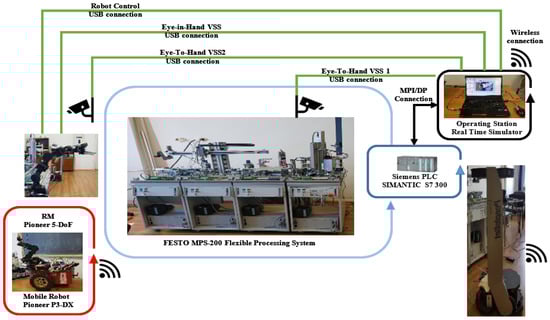
Figure 12.
Communication block set of P/RML, assisted by two ARSs, two eyes to hand and one eye in hand VSSs [9]. @2019 IEEE.
Figure 13 illustrates a series of image and frames captured during real time-control based on the eye to hand VSS located to the last station of P/RML. Additionally, Figure 13 shows the real-time steps with the precise positioning, based on eye in hand VSS, of the ARS Pioneer 3-DX equipped with RM Pioneer 5-DOF: (a) Displacement of the ARS Pioneer P3-DX and positioning to retrieve the work-piece from the P/RML, (b) catching the work-piece, (c) displacement of ARS Pioneer P3-DX to the ARS PeopleBot, based on real-time, trajectory-tracking, sliding-mode control; (d) releasing the work-piece on ARS PeopleBot, (e) return to the starting position of the ARS Pioneer P3-DX. Real-time control of ARS Pioneer 3-DX equipped with RM Pioneer 5-DOF for picking up work-piece using eye to hand VSS. Some frames of real-time control of ARS Pioneer 3-DX equipped with RM Pioneer 5-DOF for picking up work-piece using eye to hand VSS, are presented in Figure 14.
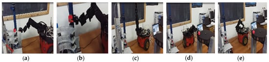
Figure 13.
Real-time control of ARS Pioneer 3-DX equipped with RM Pioneer 5-DOF corresponding to the sequences: (a) picking up the work-piece from P/RML; (b–d) transport using sliding-mode control; (e) releasing it on ARS PeopleBot.
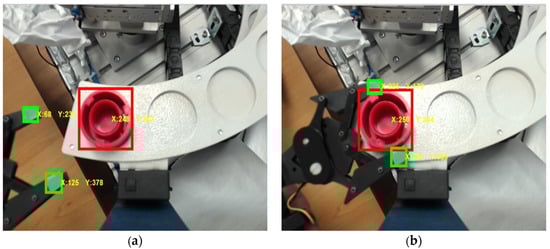
Figure 14.
Real-time control of ARS Pioneer 3-DX equipped with RM Pioneer 5-DOF using eye to hand VSS 1 as actuator for precise positioning: (a) initial gripper position; (b) final gripper position.
Figure 15 describes the trajectory with obstacle avoidance of ARS PeopleBot assisting P/RML based on TT-SMC and sensitivity bubble method (sonars located on bottom platform), [10,25,26,27]. The sensitivity bubble, shown in Figure 16, depends on the speed of movement of the robot and allows a good detection of obstacles. The components for the sensitivity bubble,, are computed using:
where: —number of readings; —component of the sensitivity bubble; —the safety factor,—robot speed; —the sample time. An obstacle is detected when the distance measured by the sonars, up to the obstacle, is smaller than the sensitivity bubble.
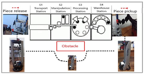
Figure 15.
Trajectory with obstacle avoidance of ARS PeopleBot assisting P/RML.
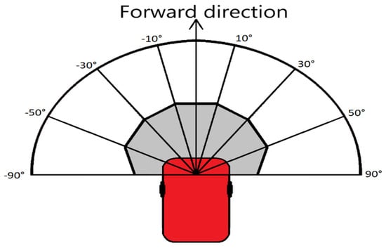
Figure 16.
Detection area of the sonars and the sensitivity bubble.
In Figure 17, it can be observed that there is an obstacle on the desired trajectory (black line) and it is desired to find a point holding the property that allows the robot to bypass the obstacle using the bypass trajectory (blue line). Knowing the width of the robot, we checked if the sonar detects another nearby obstacle in the chosen bypass direction.
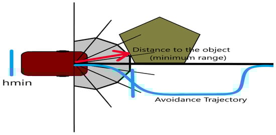
Figure 17.
Detour path to avoid the obstacle.
Figure 18 describes the following: the desired and the real trajectory of the ARS PeopleBot obtained with TT-SMC in a closed loop. A small deviation of the trajectory can be observed when ARS PeopleBot executes the return of . Figure 19 shows the tracking error when moving on the X axis and the tracking error when moving on the Y axis. When the ARS is moving on the X axis, there are two deviations due to connection loss, but they tend immediately to 0. Additionally, Figure 19 illustrates the angular error, where it can be seen that the maximum error is .
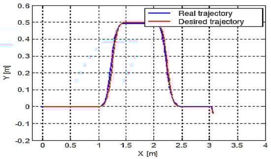
Figure 18.
Real and desired trajectory of ARS PeopleBot based on trajectory tracking sliding-mode control.
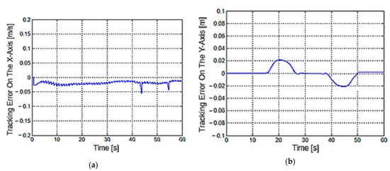
Figure 19.
(a) X-axis and (b) Y-axis motion tracking errors for ARS PeopleBot, in absolute coordinates.
Figure 20 shows the real-time control of RM Cyton based on invers kinematics, [20], eye in hand and eye to hand VSS for handling the work-piece: in the left initial position, in the middle, caching the work-piece from ARS PeopleBot, in the right, releasing the work-piece on P/RML.
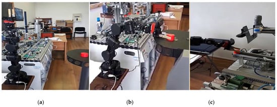
Figure 20.
Real-time control of RM Cyton based on inverse kinematics for handling the work-piece: (a) initial position; (b) caching the work-piece from ARS PeopleBot; (c) releasing the work-piece on P/RML. Eye in hand VSS and eye to hand VSS 2 as actuators for precise positioning.
Real and desired trajectories are shown in: Figure 21, corresponding to the movement of RM Cyton from initial position to the ARS PeopleBot position for picking up the work-piece from upper platform of ARS PeopleBot, using inverse kinematics control and eye in hand VSS for precision positioning; Figure 22, corresponding to the movement of RM Cyton for transporting work-piece from ARS PeopleBot to P/RML, using inverse kinematics control and eye to hand VSS for precision positioning; Figure 23 corresponding to the movements of RM Cyton from P/RML to the parking position using inverse kinematics control.
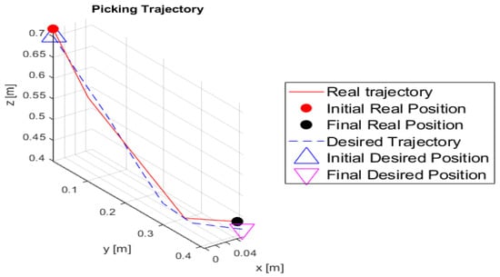
Figure 21.
Real and desired trajectory of RM Cyton from initial to the ARS PeopleBot position, for picking up the work-piece from ARS PeopleBot using inverse kinematics control and eye in hand VSS for precision positioning.
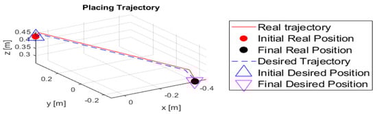
Figure 22.
Real and desired trajectory of RM Cyton for transporting work-piece from ARS PeopleBot to P/RML, using inverse kinematics control and eye to hand VSS for precision positioning.
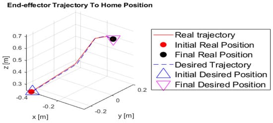
Figure 23.
Real and desired trajectory of RM Cyton, for displacement from P/RML to the parking position, using inverse kinematics control.
Some frames of real-time control of RM Cytor for picking up work-piece from ARS PeopleBot, based on eye in hand VSS and releasing it on P/RML, based on eye to hand VSS, are presented in Figure 24 and Figure 25, respectively.
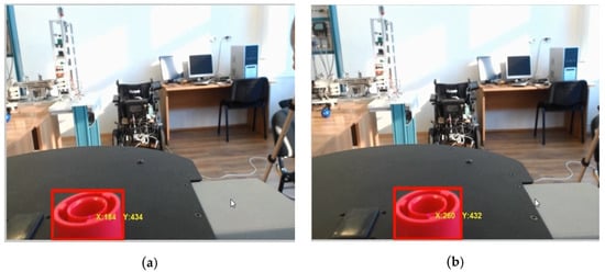
Figure 24.
Real-time control of RM Cyton for retrieving the work-piece from ARS PeopleBot based on eye in hand VSS for precise positioning: (a) (X:184, Y:434); (b) (X:260, Y:434).
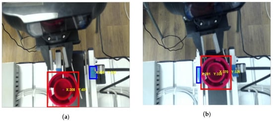
Figure 25.
Real-time control of RM Cyton for releasing the work-piece on P//RML based on eye to hand VSS 2 as actuator for precise positioning: (a) piece position = (X:184, Y:434), relative position = (X:456, Y:324); (b) piece position = (x:260, y:434), relative position = (X:370, Y:326).
6. Discussion
We mention in [5] that the SHPH model and its simulation in autonomous mode (HPN model) are based on two reasons. The first one is to make compatible the discrete dynamics of P/RML with the continuous dynamics of ARSs. The compatibility is needed because the P/RML and ARSs have characteristics and physical constraints that should be considered. The second one is due to the uncertainty introduced by the precise positioning of the RM for picking up or releasing the work-piece, because VSSs have not been implemented. Additionally, we state in [5,9,28] that the introduction of VSSs is a research objective in the near future. Assisting P/RML by VSSs, RMs and VSSs led to the elimination of an important part of the uncertainty during a complete cycle. One of the objectives of the control and monitoring of this manufacturing technology on P/RML assisted by ARSs, RMs and VSSs is the minimization of the cycle time. By using the TTSMC to control ARSs and sensitivity bubble method to avoid obstacles, the problem of system robustness was partially addressed. The following have to be considered as uncertainties: faulty sensors/actuators, route/storage space blockage and payload variation. In future research, these will also be taken into account.
7. Conclusions
The assistive technology implemented to the four workstations P/RML, FESTO MPS 200, allows the recovery, through reprocessing, of products that do not correspond qualitatively. To successfully implement this eco-technology, ARSs, RMs and VSSs are used for assistance, with the last ones as actuators for the movements of the RMs. Although it is a technology that works at the laboratory level, it can be extended to the real industry, especially in those areas where positioning and precision handling are required. Based on the SHPN model, SIMATIC STEP 7, Visual C ++ and MATLAB platforms, real-time control structures were implemented, allowing fully automatic, processing/reprocessing, assisted by ARSs, RMs and VSSs. The use of the combination of Eye in hand and Eye to hand VSS as actuators allowed the robotic systems to make precise positioning and manipulation. The signals from the sensors were used to synchronize tasks and operations. The SHPN model and its simulation were useful in combining the discrete dynamics of P/RML with the continuous one of robotic systems. This technology can be applied not only to mechatronics lines but also in manufacturing processes in metallurgy, ceramics, glass and the automotive industry. In most cases, robotic manipulators that assist these processes have fixed locations. Through this study, we extended the degree of automation and efficiency of these production lines using ARSs, RMs and VSSs.
Author Contributions
All the authors contributed extensively to the work presented in this paper and to writing the paper itself. A.F. (Adrian Filipescu), E.M., A.F. (Adriana Filipescu), H.-G.C. have conceived the idea and developed the proposed approaches. (Adrian Filipescu), E.M. and A.F. (Adriana Filipescu) gave advice on the research and helped edit the paper. A.F. (Adrian Filipescu) and E.M. improved the quality of the manuscript and the completed revision. All authors have read and agreed to the published version of the manuscript.
Funding
This work was supported by the Romanian Executive Unit of Funding Higher Education, Research, Development and Innovation (UEFISCDI), project number: PN-III-P1-1.2-PCCDI-2017-0290, project title: Intelligent and distributed control of 3 complex autonomous systems integrated into emerging technologies for medical-social personal assistance and servicing of precision flexible manufacturing lines.
Conflicts of Interest
The authors declare no conflict of interest.
References
- Syafrudin, M.; Fitriyani, N.L.; Alfian, G.; Rhee, J. An Affordable Fast Early Warning System for Edge Computing in Assembly Line. Appl. Sci. 2019, 9, 84. [Google Scholar] [CrossRef]
- Stoll, J.T.; Schanz, K.; Pott, A. Mechatronic Control System for a Compliant and Precise Pneumatic Rotary Drive Unit. Actuators 2020, 9, 1. [Google Scholar] [CrossRef]
- de Gea Fernández, J.; Yu, B.; Bargsten, V.; Zipper, M.; Sprengel, H. Design, Modelling and Control of Novel Series-Elastic Actuators for Industrial Robots. Actuators 2020, 9, 6. [Google Scholar] [CrossRef]
- Filipescu, A., Jr. Contributions to Electric Drive of the Flexible Manufacturing Lines and Integrated Robots. Ph.D. Thesis, Dunarea de Jos University of Galati, Galati, Romania, 2017. [Google Scholar]
- Dragomir, F.; Mincă, E.; Dragomir, O.E.; Filipescu, A. Modelling and Control of Mechatronics Lines Served by Complex Autonomous Systems. Sensors 2019, 19, 3266. [Google Scholar] [CrossRef] [PubMed]
- Petrea, G.; Filipescu, A.; Minca, E.; Voda, A.; Filipescu, A., Jr.; Serbencu, A. Hybrid Modelling Based Control of an Processing/Reprocessing Mechatronics Line Served by an Autonomous Robotic System. In Proceedings of the 17th IEEE, Intrenational Conference on System Theory, Control and Computing, (ICSTCC), Sinaia, Romania, 11–13 October 2013; pp. 410–415, ISBN 978-1-4799-2228-4. [Google Scholar]
- Filipescu, A., Jr.; Petrea, G.; Filipescu, A.; Filipescu, S. Modeling and Control of a Mechatronics System Served by a Mobile Platform Equipped with Manipulator. In Proceedings of the 33rd Chinese Control Conference, Nanjing, China, 28–30 July 2014; pp. 6577–6582, ISBN 978-988-15638-4-2. [Google Scholar]
- Petrea, G.; Filipescu, A.; Minca, E.; Filipescu, A., Jr. Hybrid Modelling and Simulation of a P/RML with Integrated Complex Autonomous Systems. In Proceedings of the 22th IEEE, International Conference on System Theory, Control and Computing, (ICSTCC), Sinaia, Romania, 10–12 October 2018; pp. 439–444, ISBN 978-1-5386-4444-7. [Google Scholar]
- Filipescu, A.; Minca, E.; Filipescu, A., Jr. Mechatronics Manufacturing Line with Integrated Autonomous Robots and Visual Servoing Systems. In Proceedings of the 9th IEEE International Conference on Cybernetics and Intelligent Systems, and Robotics, Automation and Mechatronics (CIS-RAM 2019), Bangkok, Thailand, 18–20 November 2019; pp. 620–625, ISBN 978-1-7281-3457-4. [Google Scholar]
- Ciubucciu, G.; Filipescu, A.; Filipescu, A., Jr.; Filipescu, S.; Dumitrascu, B. Control and Obstacle Avoidance of a WMR Based on Sliding-Mode, Ultrasounds and Laser. In Proceedings of the 12th IEEE International Conference on Control and Automation (ICCA), Kathmandu, Nepal, 1–3 June 2016; pp. 779–784, ISBN 978-1-5090-1737-9. [Google Scholar]
- Lupu, C.; Popescu, D.; Florea, G. Supervised Solutions for Precise Ratio Control: Applicability in Continuous Production Line. Stud. Inform. Control 2014, 23, 53–64. [Google Scholar] [CrossRef]
- Radaschin, A.; Voda, A.; Filipescu, A. Task Planning Algorithm in Hybrid Assembly/Disassembly Process. 14th IFAC Symp. Inf. Control Probl. Manuf. 2012, 45, 571–576. [Google Scholar] [CrossRef]
- Minca, E.; Filipescu, A.; Voda, A. Modelling and control of an assembly/disassembly mechatronics line served by mobile robot with manipulator. Control Eng. Pract. 2014, 31, 50–62. [Google Scholar] [CrossRef]
- Filipescu, A.; Filipescu, A., Jr. Simulated Hybrid Model of an Autonomous Robotic System Integrated into Assembly/Disassembly Mechatronics Line. IFAC Proc. Vol. 2014, 47, 9223–9228. [Google Scholar] [CrossRef]
- Ghomri, L.; Alla, H. Modeling and Analysis using Hybrid Petri Nets. Nonlinear Anal. Hybrid Syst. 2008, 1, 141–153. [Google Scholar] [CrossRef]
- Ghomri, L.; Alla, H. Continuous flow Systems and Control Methodology Using Hybrid Petri nets. Control Eng. Appl. Inform. 2013, 15, 106–116. [Google Scholar]
- David, R.; Alla, H. Discrete, Continuous and Hybrid Petri Nets; Springer: Berlin/Heidelberg, Germany, 2010; ISBN 978-3-642-10668-2. [Google Scholar]
- Minca, E.; Filipescu, A.; Coanda, H.G.; Dragomir, F.; Dragomir, O.E.; Filipescu, A. Extended Approach for Modelling and Simulation of Mechatronics Lines Served by Collaborative Mobile Robots. In Proceedings of the 2018 22nd International Conference on System Theory, Control and Computing (ICSTCC), Sinaia, Romania, 10–12 October 2018; pp. 335–341. [Google Scholar]
- Copot, C. Control Techniques for Visual Servoing Systems. Ph.D. Thesis, Gheorghe Asachi Technical University of Iasi, Iasi, Romania, 2012. [Google Scholar]
- Gasparetto, A.; Zanotto, V. A new method for smooth trajectory planning of robot manipulators. Mech. Mach. Theory 2007, 42, 455–471. [Google Scholar] [CrossRef]
- Kim, J.; Park, J.; Chung, W. Self-Diagnosis of Localization Status for Autonomous Mobile Robots. Sensors 2018, 18, 3168. [Google Scholar] [CrossRef] [PubMed]
- Kallrath, J. Planning and scheduling in the process industry. In Advance Planning and Scheduling Solution in Process Industry; Springer: Berlin/Heidelberg, Germany, 2003; pp. 201–227. [Google Scholar]
- Tolio, T. Design of Flexible Production Systems—Methodologies and Tools; Springer: Berlin, Germany, 2009. [Google Scholar]
- Hussain, I.; Albalasie, A.; Awad, M.I.; Gan, D. Modeling, Identification, and Control of a Discrete Variable Stiffness Actuator (DVSA). Actuators 2019, 8, 50. [Google Scholar] [CrossRef]
- Ravankar, A.; Ravankar, A.A.; Kobayashi, Y.; Hoshino, Y.; Peng, C.-C. Path Smoothing Techniques in Robot Navigation: State-of-the-Art, Current and Future Challenges. Sensors 2018, 18, 3170. [Google Scholar] [CrossRef] [PubMed]
- Brassai, S.T.; Iantovics, B.; Enăchescu, C. Optimization of Robotic Mobile Agent Navigation. Stud. Inform. Control 2012, 21, 6. [Google Scholar] [CrossRef]
- Zohaib, M.; Pasha, S.M.; Javaid, N.; Salaam, A.; Iqbal, J. An Improved Algorithm for Collision Avoidance in Environments Having U and H Shaped Obstacles. Stud. Inform. Control 2014, 23, 97–106. [Google Scholar] [CrossRef]
- Petrea, G.; Filipescu, A.; Solea, R.; Filipescu, A., Jr. Visual Servoing Systems Based Control of Complex Autonomous Systems Serving a P/RML. In Proceedings of the 22th IEEE, International Conference on System Theory, Control and Computing, (ICSTCC), Sinaia, Romania, 10–12 October 2018; pp. 323–328, ISBN 978-1-5386-4444-7. [Google Scholar]
Publisher’s Note: MDPI stays neutral with regard to jurisdictional claims in published maps and institutional affiliations. |
© 2020 by the authors. Licensee MDPI, Basel, Switzerland. This article is an open access article distributed under the terms and conditions of the Creative Commons Attribution (CC BY) license (http://creativecommons.org/licenses/by/4.0/).