Abstract
Microfluidic structures and devices have been studied over decades for the transport of liquid through internal channels using versatile microfabrication schemes such as surface and bulk micromachining technologies. One challenge in consideration of the device design involves the breakthrough of microfluidic reservoir and channels being substantially limited in two-dimensional (2D) geometry. However, recent progress of the emerging 3D printing technologies has showed great potential to overcome this problem in a simple manner. This paper comprehensively reports an additive manufacturing of polylactic acid (PLA) layers to significantly improve the complexity in the formation of the 3D microfluidic structures as compared to conventional micro-manufacturing techniques. Moreover, a handheld mechatronic device with a small height of ~10 mm, assembled with a thin planar atomizer and a micro controller, was produced and demonstrated for generation of droplets (~6 μm in diameter). Both the analytical and experimental results indicated that the grids of channel microstructures were simply varied by different line widths (300–500 μm) and spacing (250–400 μm) 3D printed within the device, thereby providing the design capability for capillary flow. In this regard, a variety of complex micro devices fabricated via computer-aided design (CAD) and the 3D printing method could be applied for more applications than ever, such as microfluidic delivery of biomedical materials and health care devices of a small size.
1. Introduction
Microfluidic structures such as flow channels, cavities and holes at micrometer scale have been applied widely for delivery of liquid flow in a variety of micro-electro-mechanical systems (MEMS) over decades [,,,]. Those microstructures were mostly designed and fabricated by the present micromachining techniques including the silicon etching [,,,], surface micromachining [,], UV-LIGA (lithography, electroplating, and molding) process [,,,], etc. For instance, based on conventional photolithography as reported previously by E. Verpoorte and N. F. de Rooij [], the planar fluidic structures created and bonded with silicon, glass and polymer substrates can be integrated with electrical and chemical functions in many applications such as drug delivery [], biomedical diagnostics [], and energy storage []. Compared to the conventional microfabrication techniques, one alternative technique called additive manufacturing or three-dimensional (3D) printing can simply generate various patterns of complex components in non-planar 3D geometry [,], thereby providing a promising method of forming versatile microstructures without etching on substrates. With various liquid or solid used as structural materials, 3D microstructures of the devices can be visualized through computer aided design (CAD) and are subsequently realized via computer aided manufacturing (CAM) using a print/jetting head or laser beam [,]. Moreover, as illustrated clearly by V. A. Lifton et al., the 3D printing (3DP) methods that primarily include stereolithography (SLA), fused deposition modeling (FDM), and selective laser sintering (SLS) appear to be compliant with coarser resolution requirements of the microfluidic devices []. In addition, recent development on extrusion-based 3D printing [,] and indirect volumetric approaches of soft-lithography [,] have made great progress, particularly in biochemical and microfluidic applications. Extending from the applications of two-dimensional (2D) printing technology to microfluidic systems [], the non-planar microfluidic components were designed and fabricated by means of 3D printing approaches [], showing more emerging opportunities for the design and fabrication of advanced mechatronics and MEMS devices [].
In addition, it is noted that different 3D printing approaches provide direct placement of out-of-plane microstructures on a surface and shall be able to be further utilized for the fabrication of MEMS, as reported recently by S. Kumar et al. []. For instance, complex 3D grid structures were fabricated by the combination of 3D printing and casting, in which a CAD model of the mold was 3D printed by binder jetting and the mold was applied for the casting of metals []. Based on this idea for 3D grid structures, our preliminary report showed that spongy microstructures can be simply made of solid polylactic acid (PLA) by utilizing the 3D printing process of FDM [], in which the direct formation of microstructures through the on-demand deposition of fused filaments was proposed for favorable merits such as simplicity and low cost when compared to those by conventional means of photolithography. In other words, the eco-friendly PLA and many thermoplastic materials such as PMMA [] are inexpensive and suitable for production of the structures. Many post-processing tasks such as sintering, casting, curing, and washing, often required for other methods [,,,], are not necessary for FDM. Hence, an efficient FDM process was applied to fabricate the 3D grid structure to demonstrate the idea using the popular PLA.
Further extended from the previous work [], in this paper, we comprehensively report the capability of complex design of adaptive structures with a thin planar atomizer, by incorporating the microfluidics and 3D printing technique into mechatronics []. Here, the multi-functional structures, including a microfluidic reservoir, a channel, and an inlet/outlet, could be integrated together within one complex grid structure by 3D printing design and fabrication; capillary flow in a micro channel from the inlet to the outlet would be spontaneously delivered due to surface tension of the liquid. In addition, the gradient structure of the channel could be enabled to facilitate the microfluidic flow driven by gradient pressure. More importantly, the gradient density of the structured channel would be simply adapted by changing 3D printing parameters, which can be efficiently carried out by the present approach. Together with a thin planar atomizer embedded in the outlet, the delivered flow would be energized by an electric battery, thus resulting in droplets generated out of a nozzle plate atop the outlet []. In this way, the small mechatronic device of liquid flow performs as a droplet generator to benefit potential applications in microfluidic devices and biochemical MEMS [,,]. The efficient use of the FDM method in the work is able to integrate the microfluidic structures with microelectronic components. Here a grid microstructure with different fluidic parts can be produced without waste of material and time. Therefore, the present work allows more selections of complex microfluidic structures that are designed and fabricated efficiently at low cost. It provides an alternative approach for various applications including drug delivery and medical therapy for personal care [,,].
The paper is structured as follows. In Section 2, we propose the physical model of a microfluidic device and microfabrication process using CAD design and the 3D printing method. In Section 3, we describe the experimental results and observations of the fluidic device with a grid structure and an atomizer. In Section 4, we discuss and analyze the findings of the microfluidic structure and performance. Finally, we draw a conclusion in Section 5.
2. Design and 3D Printing
2.1. Design of a Microfluidic Structure
We presented a novel microfluidic design of the thin planar atomizer to accomplish delivery of liquid flow through a grid microstructure integrated with different parts such as the fluidic channel, reservoir and inlet/outlet, as illustrated in Figure 1. Namely, the structure is primarily composed of internal and external regions (see (a) and (b)). The internal region is created with a fluidic inlet and a gradient channel that are filled with fluid as core parts of the structure, allowing for the entrance and transport of liquid (from an inlet to an outlet). Liquid passing the channel is bifurcated at an inclined plane of the gradient channel (see inset B in (b)). One portion of the bifurcated liquid can be directed upward to a void reservoir in the top-left corner, while the other portion moves toward the outlet in the right direction. Consequently, the forward liquid is transported to the fluidic outlet through the internal channel (see inset C in (b)), in which the cross meshes of the structure are shaped for capillary flow driven by the surface tension of the liquid. Moreover, this fluidic outlet can be assembled with a thin planar atomizer atop, thereby jetting liquid out of the channel via an electric power supply.
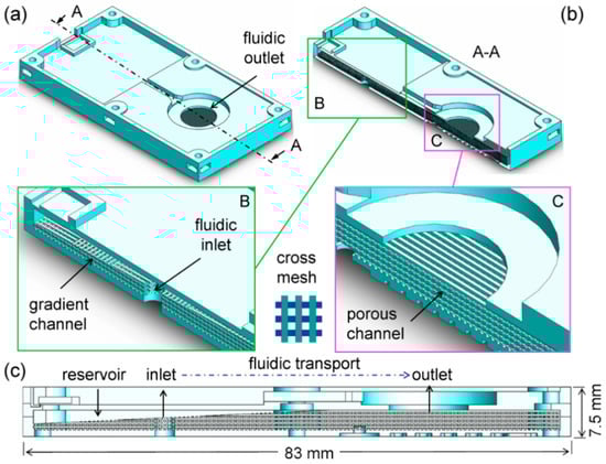
Figure 1.
Design of microfluidic channels and grid structures in the study: (a) The three-dimensional structure of main body featuring a fluidic outlet of droplets; (b) The cross-section A–A of the structure with cross meshes inside highlighting the gradient channel nearby a fluidic inlet (see inset B) and the channel in the neighborhood of the fluidic outlet (see inset C); (c) The reservoir ready for fluidic transport through the channel.
This transport of liquid through the fluidic channel, in theory, relies on its interplay of surface energy on the three-phase interface among the liquid (L) and the vapor (V), and the solid (S). From the classical Laplace’s equation for static equilibrium, the pressure difference at the solid-liquid (SL) interface, Δp, for the fluidic channel exists as follows []:
where γLV is the surface tension acting on the three-phase line between L and V, r is the equivalent capillary radius of the channel, and θCA is the contact angle between S and L (i.e., wetting as 0 < θCA < 90°). For instance, if γLV = 72 mN/m (for pure water H2O), r = 350 μm (for cross mesh), and θCA = 70° (for PLA), then Δp = 140 N/m2 (Pascal, Pa). Therefore, as liquid travels with the contact angle, it can be driven spontaneously in the micro channel due to the occurrence of surface tension.
2.2. Design of a Microfluidic Structure
To realize the microfluidic device design as mentioned above, an additive manufacturing process of the 3D grid structure is proposed in Figure 2, which is based on the current fused deposition modeling (FDM) technique []. First, a 3D printing platform is coated with a thin layer of paste adhesive in order to accept the material of thermoplastic polymer deposited on top. The 3D printing filament of material (a diameter of 1.75–3.0 mm) is then loaded into a printhead, melted by an internal heater (a melting temperature of 190–230 °C), extruded out of a nozzle (outlet diameter d of 200–400 μm), and then deposited on the adhesive (a layer thickness t of 50–200 μm), as shown in Figure 2a. After the first steps referred to as material extrusion (ME) of FDM [], the fused deposition is subsequently continued to create the rest of the structure, where it exhibits the solid and void portions. After fused deposition of all the layers, a multilayer grid structure is 3D printed with void portions for filling liquid (in the inlet) as well as solid portions for barriers (in the channel and the reservoir).
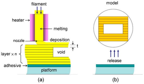
Figure 2.
Schematic of the three-dimensional (3D) printing process based on the filament deposition modeling (FDM) method: (a) The multilayer grid structure formed with a single layer thickness t featuring the inside voids such as channels and pores; (b) direct release of the 3D printed model from the underlying platform.
Thus, the grid structure is eventually produced after the final release from the underlying adhesive, as depicted in Figure 2b. Here, in regard to this layer-by-layer process in 3DP-based CAD/CAM, the total number (n) of layers with the same thickness (t), the same line width (w), and variable layer area (Ai) in the i-th layer can be determined on demand. Therefore, the total material volume of VMA deposited for the solid portion can be estimated as:
where li is the line length of filament deposited in the i-th layer and LMA is the total length of filament consumed in the 3D printing process of the structure. For instance, supposing that t = 100 μm and w = 350 μm, it yields LMA = 286 m for VMA = 10 cm3; and this can finish at a CAM time (T) of ~3 h at a printing speed (vP) of ~26 mm/s since T = LMA/vP. With a filling factor of FF and a void volume ratio of δ, the void volume of VVD and the total volume of VST for one structure are simply defined and expressed as:
Obviously, the void volume (VVD) is able to be utilized for storage of liquid in the reservoir and the channel [,]. In addition, with the assistance of the CAD software, the AM-based microfluidic channel of flow can be fine structured with a versatile texture inside for the purpose of fluidic storage and delivery, which is investigated thoroughly in the following experiments.
3. Experimental
3.1. Fused Deposition of Filament Material
In the work, a thermoplastic polyester of polylactic acid (PLA), (C3H4O2)n (melting temperature of 130–175 °C) [] and a 3D printer (Atom 2.0, Layer One Atom2dp Com., TW) [] were used to carry out the manufacturing process as illustrated previously in Figure 2a. First, a 1.75 mm-diameter PLA filament (1 kg/roll) was loaded from an external spool and fed into the printhead of the 3D printer, followed by pre-heating at 200 °C and pre-fusing smoothly through the printhead nozzle (400 μm in diameter). Secondly, after the preparation for setup of the 3D printing, the filament was subsequently extruded and deposited on the platform. The constant layer thickness of 100 μm was printed at a full speed of 30 mm/s (100%) under ambient temperature and pressure (~25 °C and 1 atm). To yield fine quality of the product, however, this deposition process should be performed at a lower speed, primarily ranging from 9 mm/s (30%) to 24 mm/s (80%). It was noticed that irregular linewidth and spacing of layers occurred at a speed beyond the upper limit of the range; in contrast, non-uniform surface of the deposited layers could be generated at a speed below the lower limit of the range. Both the printing speed and quality should be considered. In this case, as a consequence of printing at a printing speed of 22.5 mm/s (75%), the grid structure of the fluidic channel was completed with fused deposition of the PLA, featuring the FDM formation of cross meshes with a line width of ~350 μm and spacing of ~300 μm as demonstrated in Figure 3a. In addition, the layered stack of the cross-mesh deposition exhibited a layer thickness of ~100 μm as indicated in Figure 3b, thus revealing the characteristics of the LBL process based on FDM [].
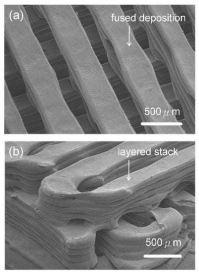
Figure 3.
The 3D printed PLA (Polylactic Acid, -(C3H4O2)-) layers of a multilayer structure based on the fused deposition modeling (FDM) method, primarily highlighting the design of grid microstructures with: (a) The cross mesh of fused deposition with a line width of about 350 μm and spacing of about 300 μm; (b) the layered stack of one single line deposition of the cross mesh with a slicing layer thickness of 100 μm.
Finally, with varying speeds for other portions, the whole structure was produced with 18.5 g (i.e., volume of 18.5/1.24 = 14.9 cm3 or mL) for ~9 h. The fabrication time could be reduced by increasing the layer thickness and/or void volume, in which the fluidic performance of delivery and storage would be altered for the structure. It can be studied for future optimization of fabrication and performance. The printed structure was further assembled with electronic parts to perform a functional test of droplet generation in the following section.
3.2. Assembly of a Microfluidic Mechatronic Device
One thin planar atomizer (WB-16A-1, Whirl Best Com., with an external diameter of 16 mm) was assembled with the outlet of the 3D printed structure (see Figure 1c) to generate droplets through its 1700 nozzles (diameter of 6–7 μm) caused by piezoelectricity, as shown in Figure 4a. It was then sealed and firmly capped with another 3D printed plate to be turned into a packaged atomizer as illustrated in Figure 4b–d. Herein the atomizer was actuated using a microelectronic controller (WB-16B-1, not shown in Figure 4) [] with an electric supply of 3–5 V by virtue of a micro USB power connector. To examine the piezoelectric effect on the generation of droplets, several experiments were performed with different driving frequencies in a range of 104–111 kHz. As shown in Figure 4e, the representative result indicated that the optimal rates of ~1 mL/min could be generated at a driving frequency of ~107 kHz. This generation rate significantly implied an effective droplet volume VDROP = (109 pL/min)/(1.07 × 105 s−1 × 60 s/min × 1.7 × 10³) = 0.1 pl, thus corresponding to a diameter DDROP = (6VDROP/π)1/3 = (6 × 0.09 × 10−15 m3/π)1/3 = 6 μm in the proximity of the nozzle diameter. Hence, for a void volume VVD = 5 mL in the fluidic channel and reservoir (i.e., a void ratio δ = 0.33 out of 14.8 mL), the total time available for droplet generation was estimated to be about 5 mL/ (1 mL/min) = 5 min in the case.
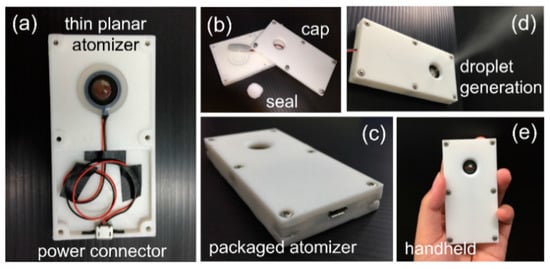
Figure 4.
One portable mechatronic fluidic device for generation of droplets: (a) Assembly of 3D printed main body with a thin planar atomizer and a power connector for driving control of droplet generation; (b) packaging of the assembled body with an internal seal and an outer cap; (c) a packaged atomizer; (d) generation of water droplets from the device; (e) handheld, compact, and light for personal use.
To further explore the reliability of fluid supply as shown in Figure 4e, different amounts of liquid were filled into the microfluidic structure for tests. In the experiments, under the normal operating environment, all of the droplets were successfully generated at the same driving condition, thereby demonstrating the reliable capillary flow throughout the cross-mesh channel of the PLA layer using pure water as a typical working liquid of daily life [,].
3.3. Tests for Generation Rate of Droplets
A series of experiments in the filling of liquid and generation of droplets for the structure were performed for evaluation of performance in the application of a thin planar atomizer. In particular, the device was able to be always laid horizontally to generate upward droplets different from those in the previous studies [,,], where the capability of droplet generation could be somewhat hindered by gravity downward. The amount of liquid volume filled inside the same device was altered nine times to find the stability and availability over time. As a result, Figure 5 shows that the liquid volume of generation (from 0.62 mL to 2.35 mL) was approximately proportional to the actuation time (from 0.47 min to 2.28 min) as expected in theory []. Based on the linear fit (regression) of the experimental data, here the rate, on average, was estimated as being close to 1.0 mL/min, consistent with the previous results []. This result indicates that the 3D printed PLA reservoir and channels were applicable to capillary flow of water in the microfluidic devices, though residues of liquid existed inevitably due to slight vacuum and gravity [].
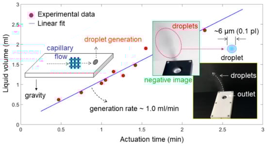
Figure 5.
Liquid volume (mL) of water droplets generated during a period of actuation time (min), in which the generation rate was approximately 1.0 mL/min based on the linear fit (regression) of nine sets of experimental data.
Moreover, the orientation of the capillary flow along the microfluidic channels could be varied simply by virtue of the 3D CAD design and printing. This is analyzed and discussed in the next section.
4. Discussion and Analysis
4.1. Reduction in Surface Roughness
Since PLA is a thermoplastic material, the surface of the 3D printed PLA should be capable of being treated thermally for flatness, where the 2D sectional profile and roughness (Ra) were particularly inspected []. This smoothening process could be beneficial for enhancement of mechanical strength on the surface; the printing defects such as voids and cavities might be also diminished to prevent leakage of liquid from the fluidic reservoir and channels. To modify the surface flatness, one PLA specimen with a size of 20 mm × 10 mm was fabricated by 3D printing and clamped between two flat plates of glass by weights. Then, it was heated in a vacuum oven at 190 °C and 400 mmHg for 30 min, as illustrated in Figure 6a. In particular, it is noticed that the plate of glass was measured by a laser scanning microscope (Keyence, JP) with a roughness of 0.022 μm, thereby providing it with a fine contact surface for thermal pressing.
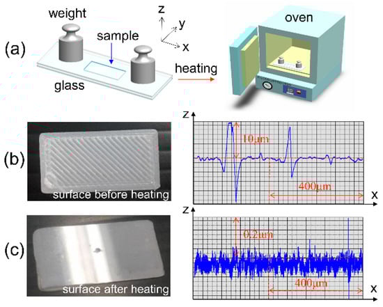
Figure 6.
Surface modification of a 3D printed structure of polylactic acid (PLA) material: (a) Thermal treatment within a vacuum oven, and 2D profiling of the PLA specimen with a roughness Ra = 1.12 μm before treatment in (b) and Ra = 0.023 μm after treatment in (c).
As shown in Figure 6b, the PLA specimen obviously featured a wavy surface with a maximum rise of ~10 μm due to the fabrication of 3D printing by FDM. The roughness of Ra for the wavy surface was obtained with a value of 1.12 μm before thermal treatment. However, the wavy surface was flattened with a Ra of 0.023 μm, approaching that of the glass surface, as shown in Figure 6c. In addition, with the roughness of Ra 49-fold smaller than previous one (i.e., 1.12/0.023 = 49), one might expect fine sealing and shining properties of the surface for the prevention of potential leaking of liquid as supplied for the outermost capped layers of a packaged microfluidic structure [,]. Therefore, this treatment would beneficial to commercial production and packaging of 3D Printed microfluidic devices in future use [,].
4.2. Characteristics of the Grid Structures
Taking advantage of the flexibility of the CAD/CAM in 3D printing, the grid structures can be simply varied in line width (w) and spacing (s) of layers. Here, nine specimens of PLA were designed with the same size (i.e., length × width × height = 35 mm × 25 mm × 56 mm and VST = 49 cm3 in volume) but different combinations of width (w = 300–500 μm) and spacing (s = 250–400 μm). As illustrated in Figure 7, each of them (No. 1–9) was produced in less than 11 h, which can be estimated with solid volumes (VMA) of less than 40 cm3 according to the previous Equation (2). The nine formations after 3D printing appeared similarly in a grid structure. However, the actual line widths of specimens deviating from designed ones were estimated with values of 301 μm (No. 9) to 656 μm (No.1), while the actual spacing was estimated in a range of 185–463 μm, as detailed individually in Table 1. In addition, their solid volumes (VMA) were estimated with 20.30–38.33 mL (cm3) using a precision balance (Precisa XS125A-SCS, Switzerland) and material density (i.e., 1.24 g/cm3 for PLA). Thus, the void volumes (VVD) and porosities (δ) of the grid structures were obtained with 10.67–28.70 mL (cm3) and 22–59%, respectively, thus corresponding to the previous Equations (3) and (4).
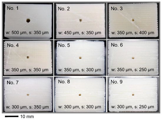
Figure 7.
Nine specimens of 3D printed grid structures of PLA with a variety of feature dimensions in computer-aided design, where the line width (w) and spacing (s) are combined within a range of 250 μm to 500 μm.

Table 1.
Measurement and comparison of capillary equilibrium for the nine samples of porous network structures fabricated by the 3D printing method of PLA in the study.
Furthermore, using the Equation (1), the Laplace’s pressures (Δp) of water (γLV = 72 mN/m) caused by the capillary effect on the square pore (r = s/2) were estimated with 166–324 Pa, where the contact angle of the PLA surface was estimated with θCA = 78°. Thus, the liquid height (hC) and liquid volume (VL), in which it remains static in capillary equilibrium with the liquid weight, can be expressed below [,]:
where ρL is the liquid density, g is the gravitational acceleration, and hST is the height of the structure, respectively. Using Equations (5) and (6) with ρL = 1.00 g/cm2 and g = 9.81 m/s2, the theoretical height hC = 1.3–3.3 cm and the theoretical liquid volume VL = 5.98–9.38 mL. It was noticed that the height could be increased for capillary pressure on the surface using liquid with low surface energy; nevertheless, this would also diminish the jetting speed of droplets as driving the atomizer. In this case, it was propriate for the thin-plate device. Hence, this ensured that the capillary pressure was sufficient to drive the flow of liquid from the lower inlet into the upper atomizer, as shown previously in Figure 4.
Eventually, the actual liquid volume of 6.53–9.89 mL was estimated from the experimental measurement as shown in Table 1, agreeing with the theoretical volumes, of which the error from 1% (No. 4) to 27% (No. 3) was yielded, with 11% on average. Furthermore, these various errors implied the irregularity and inaccuracy of the 3D printed microstructures in cross-mesh shape and at micro-scale dimension. Compared to the dimensions in CAD, linewidth (w) of 300–500 μm and spacing (s) of 250–400 μm, the estimated dimensions showed actual values of 301–656 μm (linewidth) and 195–277 μm (spacing) with a variety in deviation. This could be improved further, along with the rapid progress of versatile 3D printing technologies, in the future [,].
4.3. Capillary Liquid Flow within a Grid Structure
Finally, we designed and fabricated small grid structures (4.2 mm × 4.2 mm × 2 mm, VST = 35.3 μL) to demonstrate the capillary liquid supply, in which the red liquid (ink) was used, making it visible for the filling process []. As one representative example displayed in Figure 8, each of the four liquid droplets with an individual volume of 2.5–3.5 μL was consecutively generated and filled into the porous channels (designed with w: 300 μm, s: 200 μm, δ = 0.4 and VVD = 14.1 μL). As a result, it was observed that the flow was generated, in each case, within a few seconds (i.e., 1–5 s) due to the capillary effect moving faster along the channel (i.e., y-direction, see (b) and (c)) than rising up (i.e., z-direction, see (d) and (e)) to fill it up in a height of 2 mm with four droplets (VL = 10–14 μL approaching VVD). Nevertheless, the flow rate, dynamically in motion of liquid, shall be higher than that needed (1 μL/s in the order of magnitude) to satisfy the requirement for the rate of droplet generation when applied for an atomizer (e.g., 1 mL/min = 16.7 μL/s). To further explore the influence of line spacing (s) on the capillary flow, another grid structure with gradient spacing (Δs = 50 μm) was designed and 3D printed, in which the linewidth remained constant (w = 300 μm) for different spacing (s = 200–450 μm), as shown in Figure 9. It showed the fast capillary flow transforming in a few seconds: the droplet was filled and directed spontaneously from the coarser areas (i.e., larger spacing) to the finer ones (i.e., smaller spacing) in the 3D grid structure. This evidence significantly indicated that the droplets out of nozzles shown in Figure 5 were substantially pumped through the microfluidic grid channels. This verified the essential performance of liquid supply for droplet generation expected in conceptual design. Furthermore, the loss of driving pressure due to friction on irregular channel walls should be taken into account in future studies [,].
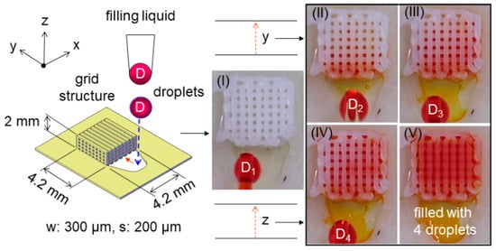
Figure 8.
Demonstration of capillary liquid supply into a 3D printed grid structure (4.2 mm × 4.2 mm × 2 mm) from each droplet of 2.5–3.5 μL generated by a pipette: (I)–(IV) consecutive droplets from the first D1 to the fourth D4 and (V) filled with the 4 droplets of 10–14 μL in total.
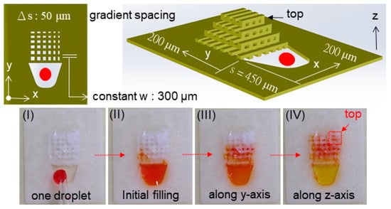
Figure 9.
Demonstration of one droplet (I) into a 3D printed grid structure with a constant line width (w = 300 μm) and gradient spacing (s = 200–450 μm, Δs = 50 μm) using a pipette: continuous motion of capillary flow through the initial filling (II), secondary transport along the y-axis (III), and final rise along the z-axis (IV) eventually reaching the top.
In this way, this fundamental design of quasi-static processes within the grid structures can be also led toward the 3D channels with gradient changes of line width and spacing. Microfluidic atomizers based on the novel design can be produced for present and future applications such as pulmonary drug delivery and spray cooling [,]. In addition to droplet generation as an atomizer, the combinational approach of 3D printing techniques and microfluidics can be cost-effective and versatile, attributes that are demanded in more applications than ever. In the future, this can be utilized as a fundamental 3D platform to adaptively realize more microfluidic devices for the delivery of biochemical materials [,,].
5. Conclusions
In the paper, we report a FDM approach based on 3D printing techniques to fabricate three-dimensional (3D) grid structures of a microfluidic device featuring the micro channels (for the supply of liquid) and micro actuation (for generation of droplets). Analytical and experimental results showed that the liquid was able to be filled into the 3D printed channels and was then jetted, constantly forming droplets after fluidic actuation, thus providing an alternative method for flexible design and efficient manufacturing at low cost. All the grid structures mainly composed of the reservoir and the fluidic channels were able to serve for the supply of liquid based on the combination of the piezoelectric and capillary effects. Finally, their solid and fluidic performances of grid structures, such as surface properties and capillary flow, were verified to demonstrate potential applications of versatile microfluidic devices in the future.
Author Contributions
Conceptualization, methodology, funding acquisition, supervision, project administration, writing—original draft preparation, C.-T.C.; software, validation, investigation, H.-F.H. All authors have read and agreed to the published version of the manuscript.
Funding
This research was funded by the National Kaohsiung University of Science and Technology (NKUST, the former National Kaohsiung University of Applied Sciences, KUAS) and the Ministry of Science and Technology (MOST) in Taiwan, ROC.
Conflicts of Interest
The authors declare no conflict of interest.
References
- Verpoorte, E.; De Rooij, N.F. Microfluidics meets MEMS. Proc. IEEE 2003, 91, 930–953. [Google Scholar] [CrossRef]
- Yoon, Y.K.; Park, J.H.; Allen, M.G. Multidirectional UV lithography for complex 3-D MEMS structures. J. Microelectromech. Syst. 2006, 15, 1121–1130. [Google Scholar] [CrossRef]
- Zhang, J.; Tan, K.L.; Hong, G.D.; Yang, L.J.; Gong, H.Q. Polymerization optimization of SU-8 photoresist and its applications in microfluidic systems and MEMS. J. Micromech. Microeng. 2001, 11, 20–26. [Google Scholar] [CrossRef]
- Tsai, N.C.; Sue, C.Y. Review of MEMS-based drug delivery and dosing systems. Sens. Actuators A-Phys. 2007, 134, 555–564. [Google Scholar] [CrossRef]
- Liu, C. Recent development in polymer MEMS. Adv. Mater. 2007, 19, 3783–3790. [Google Scholar] [CrossRef]
- Fachin, F.; Chen, G.D.; Toner, M.; Wardle, B.L. Integration of bulk nanoporous elements in microfluidic devices with applications to biomedical diagnostics. J. Microelectromech. Syst. 2011, 20, 1428–1438. [Google Scholar] [CrossRef]
- Lee, K.B.; Lin, L. Surface micromachined glass and polysilicon microchannels using MUMPs for BioMEMS applications. Sens. Actuators A-Phys. 2004, 111, 44–50. [Google Scholar] [CrossRef]
- Lifton, V.A.; Simon, S.; Holmqvist, J.; Ebefors, T.; Jansson, D.; Svedin, K. Design and fabrication of addressable microfluidic energy storage MEMS device. J. Microelectromech. Syst. 2012, 21, 1392–1400. [Google Scholar] [CrossRef]
- Chen, C.T.; Tsai, T.W. Multilayer polymer light guides integrated with refractive microlenses and liquid by micromolding and inkjet printing. Sens. Actuators A-Phys. 2016, 111, 252–260. [Google Scholar] [CrossRef]
- Guo, N.; Leu, M.C. Additive manufacturing: Technology, applications and research needs. Front. Mech. Eng. 2013, 8, 215–243. [Google Scholar] [CrossRef]
- Li, F.; Macdonald, N.P.; Guijt, R.M.; Breadmore, M.C. Microfluidic chips made by fused deposition modeling 3D printing. Anal. Chem. 2017, 89, 12805–12811. [Google Scholar] [CrossRef] [PubMed]
- Xing, J.F.; Zheng, M.L.; Duan, X.M. Two-photon polymerization microfabrication of hydrogels: An advanced 3D printing technology for tissue engineering and drug delivery. Chem. Soc. Rev. 2015, 44, 5031–5039. [Google Scholar] [CrossRef] [PubMed]
- Lee, J.Y.; Tan, W.S.; An, J.; Chua, C.K.; Tang, C.Y.; Fane, A.G.; Chong, T.H. The potential to enhance membrane module design with 3D printing technology. J. Membr. Sci. 2016, 499, 480–490. [Google Scholar] [CrossRef]
- Lifton, V.A.; Lifton, G.; Simon, S. Options for additive rapid prototyping methods (3D printing) in MEMS technology. Rapid Prototyp. J. 2014, 20, 403–412. [Google Scholar] [CrossRef]
- Parekh, D.; Ladd, C.; Panich, L.; Moussa, K.; Dickey, M. 3D printing of liquid metals as fugitive inks for fabrication of 3D microfluidic channels. Lab Chip 2016, 16, 1812–1820. [Google Scholar] [CrossRef]
- Ozbolat, V.; Dey, M.; Ayan, B.; Ozbolat, I.T. Extrusion-based printing of sacrificial Carbopol ink for fabrication of microfluidic devices. Biofabrication 2019, 11, 034101. [Google Scholar] [CrossRef]
- Helmer, D.; Voigt, A.; Wagner, S.; Keller, N.; Sachsenheimer, K.; Kotz, F.; Nargang, T.M.; Rapp, B.E. Suspended liquid subtractive lithography: One-step generation of 3D channel geometries in viscous curable polymer matrices. Sci. Rep. 2017, 7, 7387. [Google Scholar] [CrossRef]
- Gong, H.; Bickham, B.P.; Woolley, A.T.; Nordin, G.P. Custom 3D printer and resin for 18 μm × 20 μm microfluidic flow channels. Lab Chip 2017, 17, 2899–2909. [Google Scholar] [CrossRef]
- Cooley, P.; Wallace, D.; Antohe, B. Applications of ink-jet printing technology to bioMEMS and microfluidic systems. Proc. SPIE 2001, 4560, 177–188. [Google Scholar]
- Hwang, Y.; Paydar, O.H.; Candler, R.N. 3D printed molds for non-planar PDMS microfluidic channels. Sens. Actuators A-Phys. 2015, 226, 137–142. [Google Scholar] [CrossRef]
- Serien, D.; Morimoto, Y.; Takeuchi, S. Photo-induced fabrication technology for 3D microdevices. In Advanced Mechatronics and MEMS Devices II; Zhang, D., Wei, B., Eds.; Springer: Cham, Switzerland, 2017; pp. 469–494. [Google Scholar]
- Kumar, S.; Bhushan, P.; Pandey, M.; Bhattacharya, S. Additive manufacturing as an emerging technology for fabrication of micoelectromechanical systems (MEMS). J. Micromanuf. 2019, 2, 175–197. [Google Scholar] [CrossRef]
- Snelling, D.; Li, Q.; Meisel, N.; Willaims, C.B.; Batra, R.C.; Druschitz, A.P. Lightweight metal cellular structures fabricated via 3D printing of sand cast molds. Adv. Eng. Mater. 2015, 17, 923–932. [Google Scholar] [CrossRef]
- Chen, C.T.; Hsu, S.F. AM of three-dimensional spongy microstrucures for a piezoelectric sprayer. Micro Nano Lett. 2018, 13, 1662–1666. [Google Scholar] [CrossRef]
- Kotz, F.; Mader, M.; Dellen, N.; Risch, P.; Kick, A.; Helmer, D.; Rapp, B.E. Fused deposition modeling of microfluidic chips in polymethylmethacrylate. Micromachines 2020, 11, 873. [Google Scholar] [CrossRef] [PubMed]
- Mostafaei, A.; Elliott, A.M.; Barnes, J.E.; Li, F.; Tan, F.; Cramer, C.L.; Mandwana, P.; Chmielus, M. Binder jet 3D printing—Process parameters, materials, properties, and challenges. Prog. Mater. Sci. 2020. [Google Scholar] [CrossRef]
- Wu, D.; Zhao, Z.; Zhang, Q.; Qi, H.J.; Fang, D. Mechanics of shape distortion of DLP 3D printed structures during UV post-curing. Soft Matter 2019, 15, 6151–6159. [Google Scholar] [CrossRef]
- Al-Ketan, O.; Pelanconi, M.; Ortona, A.; Abu Al-Rub, R.K. Additive manufacturing of architected catalytic ceramic substrates based on triple periodic minimal surfaces. J. Am. Ceram. Soc. 2019, 102, 6176–6193. [Google Scholar] [CrossRef]
- Chen, C.T.; Huang, C.C. Microelectroforming and evaluation of honeycomb-groove nozzle plates of piezoelectric actuators for microspray generation. J. Micro/Nanolithogr. MEMS MOEMS 2016, 15, 035002. [Google Scholar] [CrossRef]
- Zhang, Y.; Ge, S.; Yu, J. Chemical and biochemical analysis on lab-on-a-chip devices fabricated using three-dimensional printing. Trends Anal. Chem. 2016, 85, 166–190. [Google Scholar] [CrossRef]
- Khalid, N.; Kobayashi, I.; Nakajima, M. Recent lab-on-chip developments for novel drug discovery. WIREs Syst. Biol. Med. 2017, 9, e1381. [Google Scholar]
- Metcalf, A.R.; Narayan, S.; Dutcher, C.S. A review of microfluidic concepts and applications for atmospheric aerosol science. Aerosol Sci. Tech. 2018, 52, 310–329. [Google Scholar] [CrossRef]
- Wallin, M.; Tagami, T.; Chen, L.; Yang, M.; Chan, H.K. Pulmonary drug delivery to older people. Adv. Drug Deliv. Rev. 2018, 135, 50–61. [Google Scholar] [CrossRef]
- Yan, X.; Yu, M.; Ramakrishna, S.; Russell, S.J.; Long, Y.Z. Advances in portable electrospinning devices for in situ delivery of personalized would care. Nanoscale 2019, 11, 19166–19178. [Google Scholar] [CrossRef]
- Farzal, Z.; Basu, S.; Burke, A.; Bs, O.O.F.; Lopez, E.M.; Bennett, W.D.; Ebert, C.S.; Zanation, A.M.; Senior, B.A.; Kimbell, J.S. Comparative study of simulated nebulized and spray particle deposition in chronic rhinosinusitis patients. Int. Forum Allergy Rhinol. 2019, 9, 746–758. [Google Scholar] [CrossRef]
- Navascues, G. Liquid surfaces: Theory of surface tension. Rep. Prog. Phys. 1979, 42, 1131–1186. [Google Scholar] [CrossRef]
- Avinc, O.; Khoddami, A. Overview of poly(lactic acid) (PLA) fibre. Fibre Chem. 2009, 41, 391–401. [Google Scholar] [CrossRef]
- Layer One Company (ATOM). Available online: https://atom3dp.com/en/ (accessed on 1 October 2020).
- Chen, H.; Cheng, W.; Peng, Y.; Zhang, W.; Jiang, L. Experimental study on optimal spray parameters of piezoelectric atomizer based spray cooling. Int. J. Heat Mass Transf. 2016, 103, 57–65. [Google Scholar] [CrossRef]
- Baran, E.H.; Erbil, H.Y. Surface modification of 3D printed PLA objects by fused deposition modeling: A review. Colloids Interfaces 2019, 3, 43. [Google Scholar] [CrossRef]
- Waldbaur, A.; Kittelmann, J.; Padtke, C.P.; Hubbuch, J.; Rapp, B.E. Microfluidics on liquid handling stations (μF-on-LHS): An industry compatible chip interface between microfluidics and automated liquid handling stations. Lab Chip 2013, 13, 2337–2343. [Google Scholar] [CrossRef]
- Li, M.; Lai, C.; Zheng, Q.; Han, B.; Wu, H.; Fan, H. Design and mechanical properties of hierarchical isogrid structures validated by 3D printing technique. Mater. Des. 2019, 168, 107664. [Google Scholar] [CrossRef]
- Ahmed, K.; Shiblee, N.I.; Khosla, A.; Nagahara, L.; Thundat, T.; Furukawa, H. Review- recent progress in 4D printing of gel materials. J. Electrochem. Soc. 2020, 167, 037563. [Google Scholar] [CrossRef]
- Maurel, A.; Grugeon, S.; Fleutot, B.; Courty, M.; Prashantha, K.; Tortajada, H.; Armand, M.; Panier, S.; Dupont, L. Three-dimensional printing of a LiFePO4/graphite battery cell via fused deposition modeling. Sci. Rep. 2019, 9, 18031. [Google Scholar] [CrossRef] [PubMed]
- Zhang, Y. Post-printing surface modification and functionalization of 3D-printed biomedical device. Int. J. Bioprinting 2017, 3, 93–99. [Google Scholar] [CrossRef]
- Olanrewaju, A.; Beaugrand, M.; Yafla, M.; Juncker, D. Capillary microfluidics in microchannels: From microfluidic networks to capillaric circuits. Lab Chip 2018, 18, 2323–2347. [Google Scholar] [CrossRef]
Publisher’s Note: MDPI stays neutral with regard to jurisdictional claims in published maps and institutional affiliations. |
© 2020 by the authors. Licensee MDPI, Basel, Switzerland. This article is an open access article distributed under the terms and conditions of the Creative Commons Attribution (CC BY) license (http://creativecommons.org/licenses/by/4.0/).