Novel Design and Modeling of a Soft Pneumatic Actuator Based on Antagonism Mechanism


Abstract
1. Introduction
2. Design and Fabrication
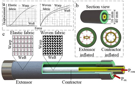
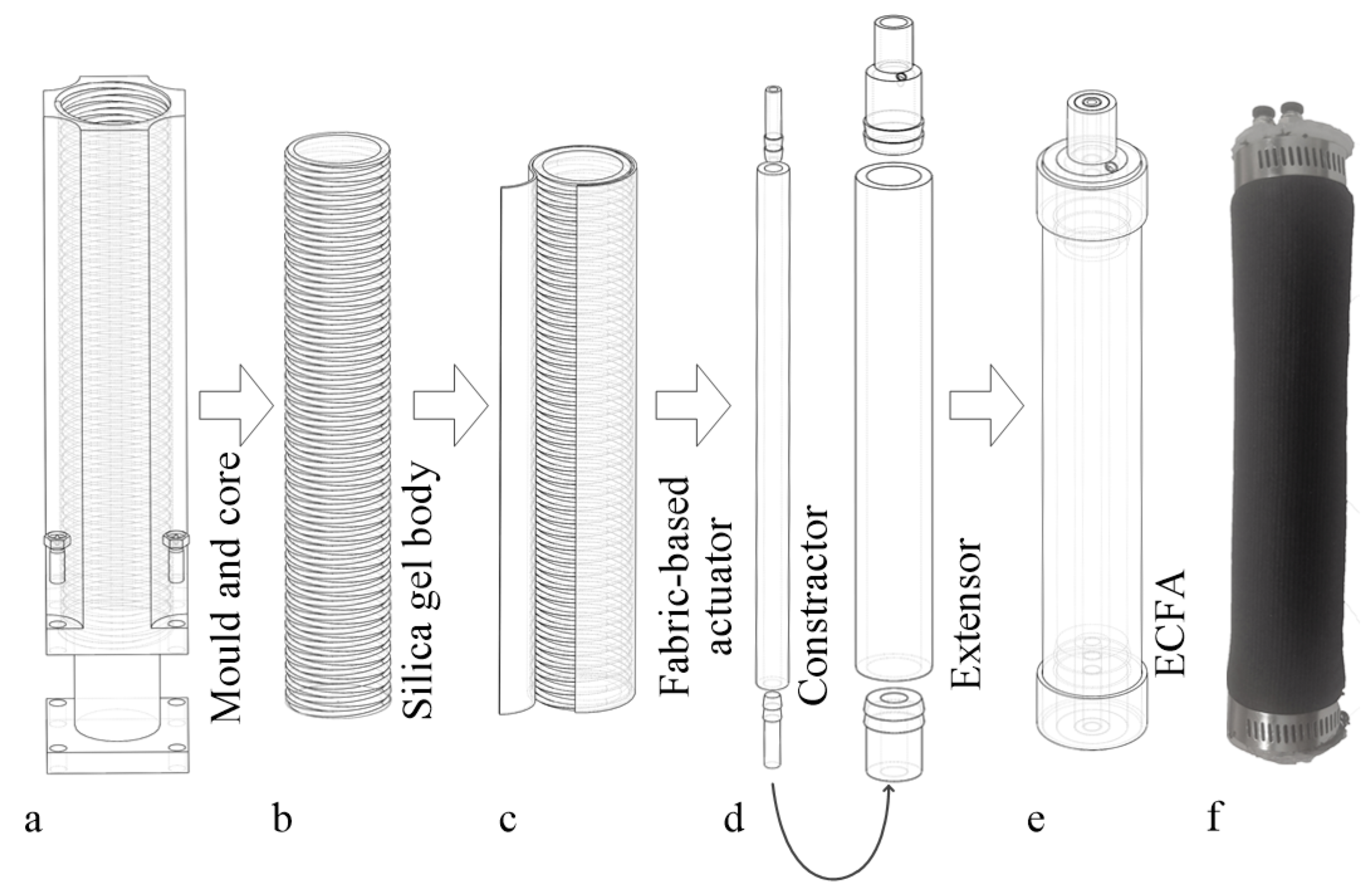
2.1. Design
- The pneumatic artificial muscle only generates a contraction force when pressurizing.
- The extensor actuator only generates extension force when pressurizing.
- Each soft actuator type has an invariable stiffness at a specific length.
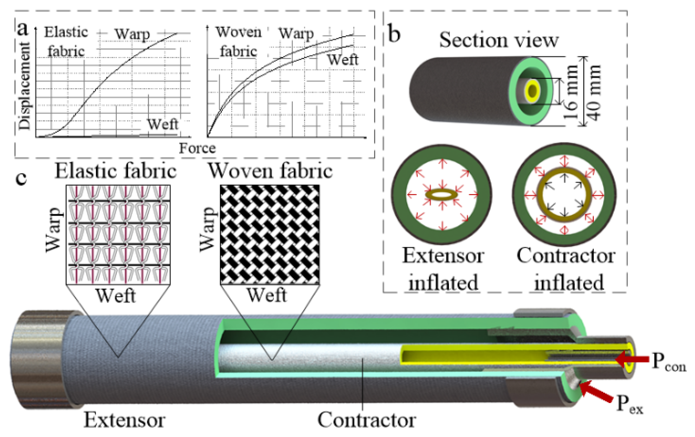
2.2. Fabrication
3. Mathematical Model
4. Experimental Verification
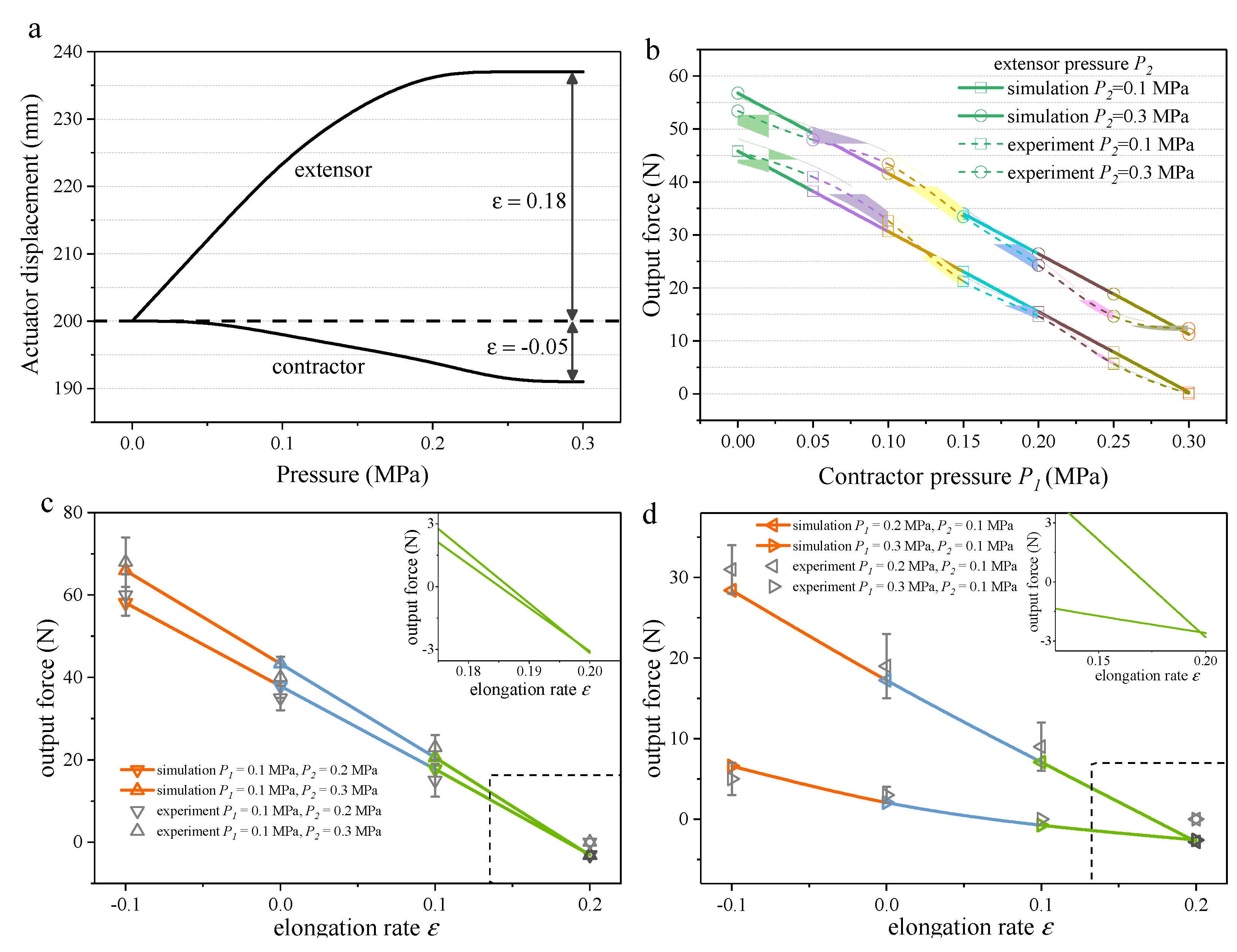
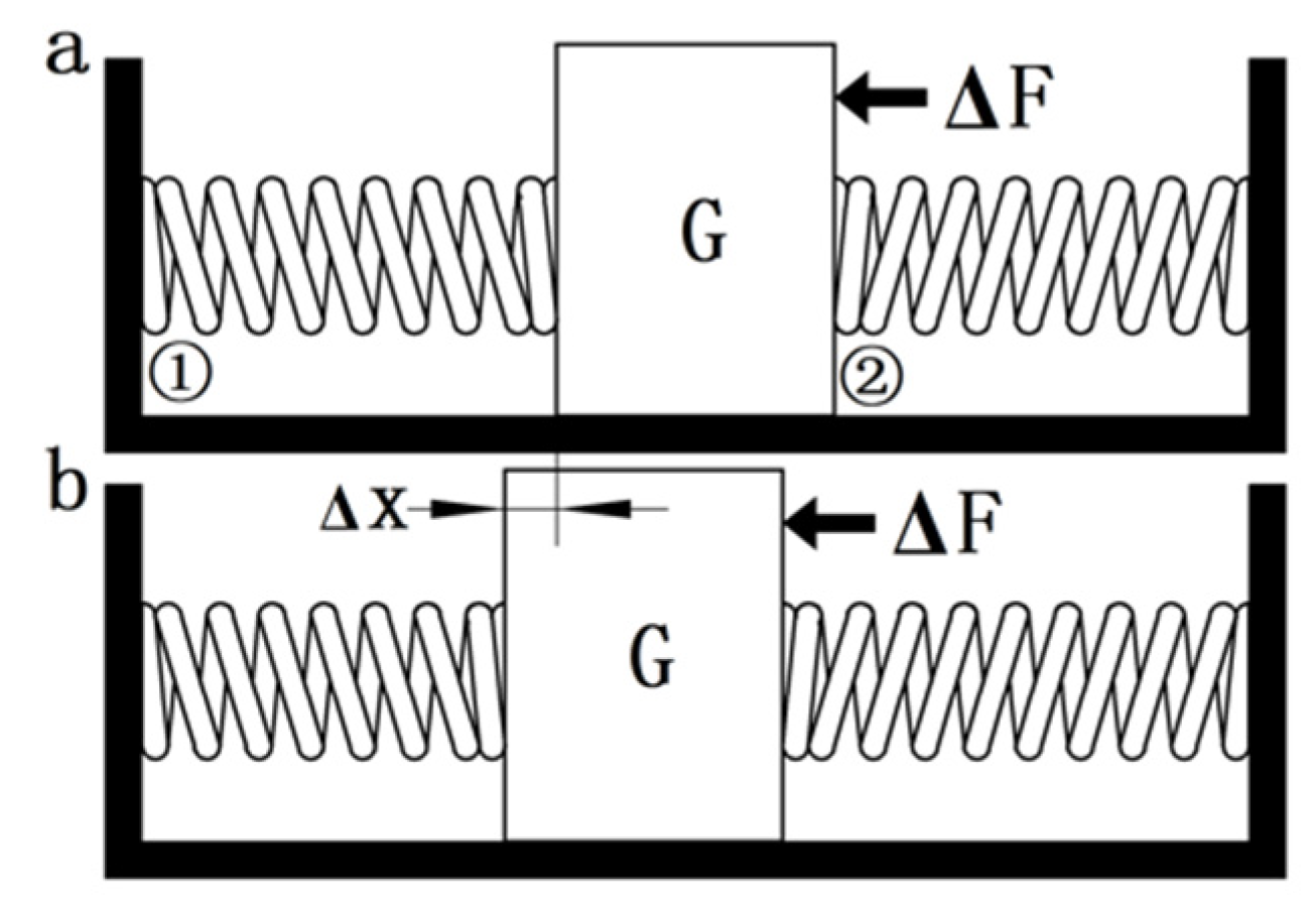
4.1. Static Force Analysis
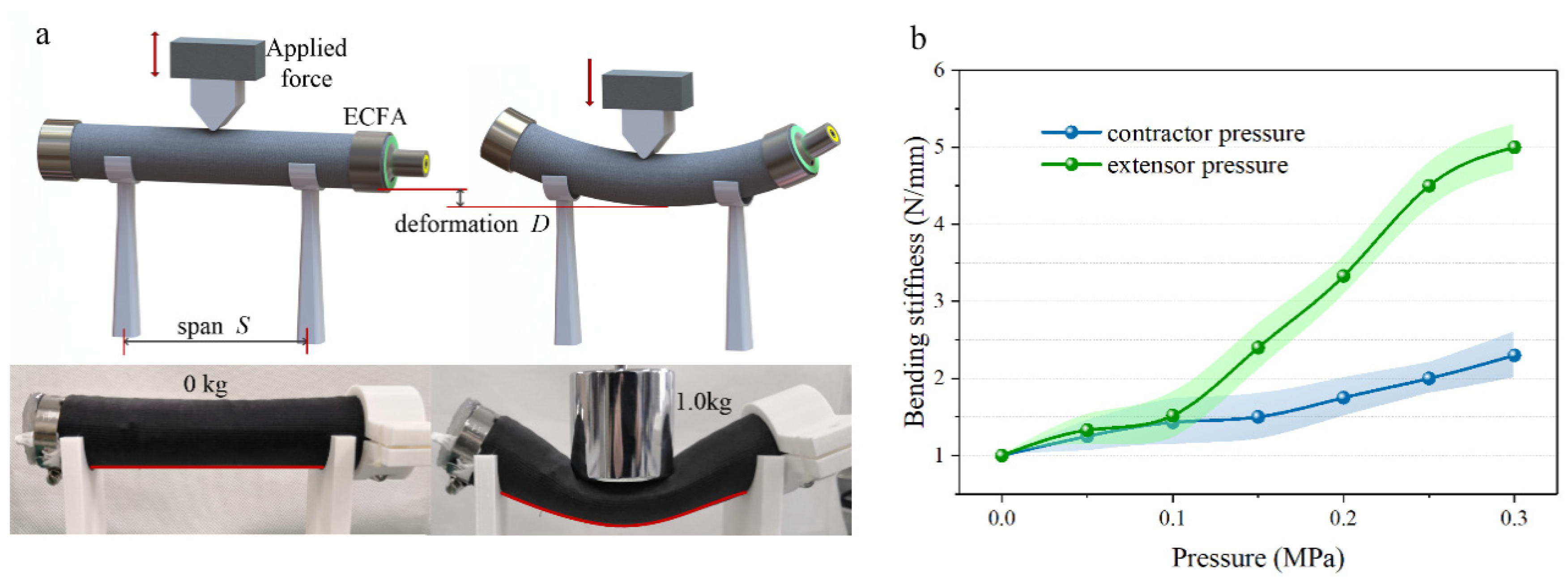
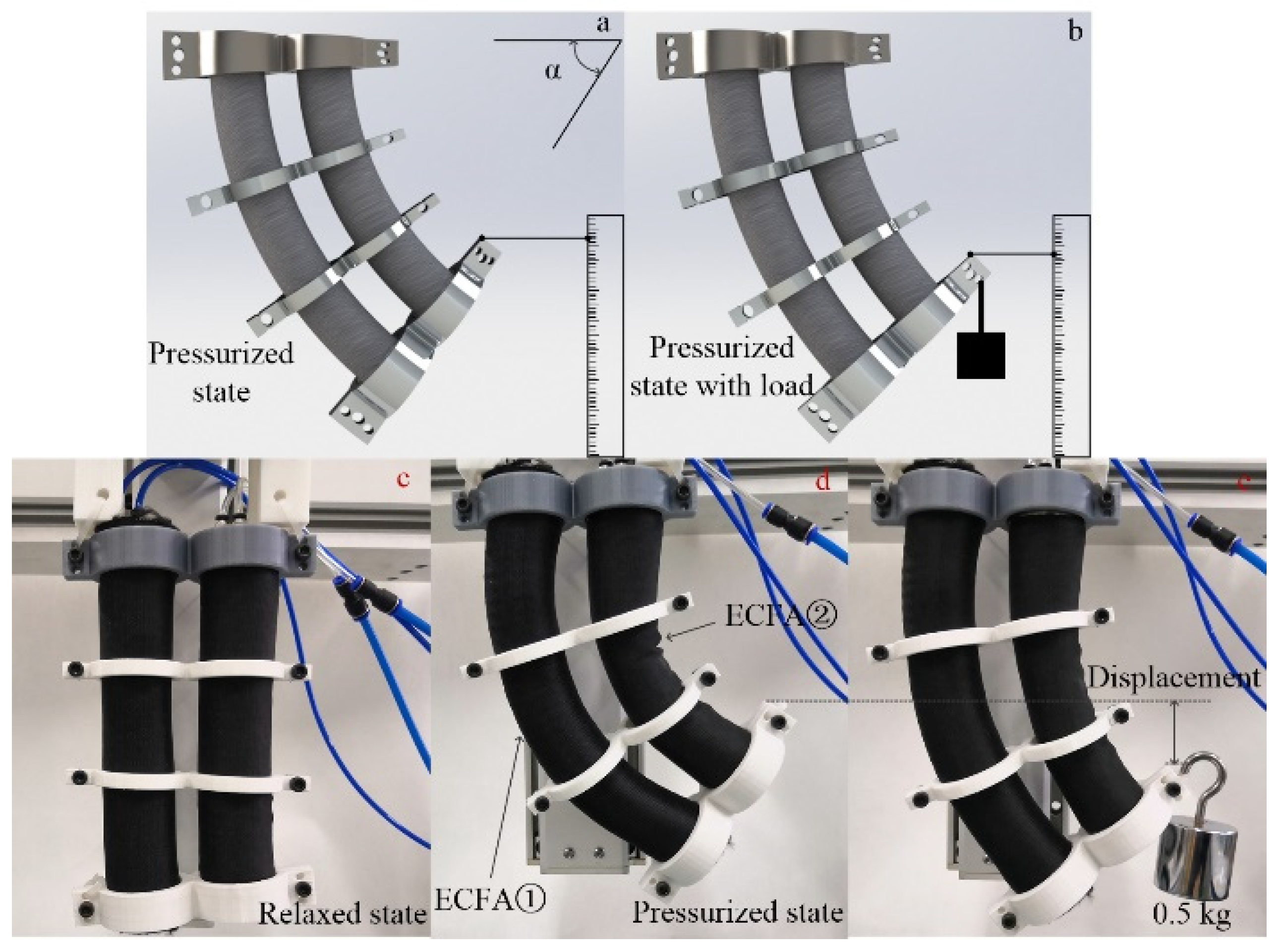
4.2. Static Stiffness Analysis
5. Conclusions
Author Contributions
Funding
Acknowledgments
Conflicts of Interest
References
- Tadano, K.; Akai, M.; Kadota, K.; Kawashima, K. Development of grip amplified glove using bi-articular mechanism with pneumatic artificial rubber muscle. In Proceedings of the IEEE International Conference on Robotics & Automation IEEE, Anchorage, AK, USA, 3–7 May 2010. [Google Scholar]
- Wang, Y.K.; Guo, C.; Li, J.; Wang, Z.L. Design of a Flexible Bending Biomimetic Octopus Arm Unit with Embedded SMA Wires. Appl. Mech. Mater. 2010, 44, 2543–2547. [Google Scholar] [CrossRef]
- Chiba, S.; Waki, M.; Wada, T.; Hirakawa, Y.; Masuda, K.; Ikoma, T. Consistent ocean wave energy harvesting using electroactive polymer (dielectric elastomer) artificial muscle generators. Appl. Energy 2013, 104, 497–502. [Google Scholar] [CrossRef]
- Ansari, Y.; Manti, M.; Falotico, E.; Mollard, Y.; Cianchetti, M.; Laschi, C. Towards the development of a soft manipulator as an assistive robot for personal care of elderly people. Int. J. Adv. Robot. Syst. 2017, 14, 1–17. [Google Scholar] [CrossRef]
- Manti, M.; Thuruthel, T.G.; Falotico, F.P.; Pratesi, A.; Falotico, E.; Cianchetti, M.; Laschi, C. Exploiting morphology of a soft manipulator for assistive tasks. In Proceedings of the Conference on Biomimetic and Biohybrid Systems, Stanford, CA, USA, 25–28 July 2017; Springer: Cham, Switzerland, 2017; pp. 291–301. [Google Scholar]
- Kim, Y.J.; Cheng, S.; Kim, S.; Iagnemma, K. A novel layer jamming mechanism with tunable stiffness capability for minimally invasive surgery. IEEE Trans. Robot. 2013, 29, 1031–1042. [Google Scholar] [CrossRef]
- Ranzani, T.; Gerboni, G.; Cianchetti, M.; Menciassi, A. A bioinspired soft manipulator for minimally invasive surgery. Bioinspir. Biomim. 2015, 10, 035008. [Google Scholar] [CrossRef] [PubMed]
- Olaru, R.; Salceanu, A.; Calarasu, D.; Cotae, C. Magnetic fluid actuator. Sens. Actuators A 2000, 81, 290–293. [Google Scholar] [CrossRef]
- Manti, M.; Pratesi, A.; Falotico, E.; Cianchetti, M.; Laschi, C. Soft assistive robot for personal care of elderly people. In Proceedings of the IEEE International Conference on Biomedical Robotics and Bio-mechatronics, Singapore, 26–29 June 2016; pp. 833–838. [Google Scholar]
- Yi, J.; Chen, X.; Song, C.; Wang, Z. Fiber Reinforced Origamic Robotic Actuator. Soft Robot. 2018, 5, 81–92. [Google Scholar] [CrossRef] [PubMed]
- Najmuddin, W.S.W.A.; Mustaffa, M.T. A study on contraction of pneumatic artificial muscle (PAM) for loadlifting. J. Phys. Conf. Ser. 2017, 908, 012036. [Google Scholar] [CrossRef]
- Al-Ibadi, A.; Nefti-Meziani, S.; Davis, S. Novel models for the extension pneumatic muscle actuator performances. In Proceedings of the 2017 23rd International Conference on Automation and Computing (ICAC), Huddersfield, UK, 7–8 September 2017. [Google Scholar]
- Chen, Y.; Zhang, J.; Gong, Y. Utilizing Anisotropic Fabrics Composites for High-Strength Soft Manipulator Integrating Soft Gripper. IEEE Access 2019, 7, 127416–127426. [Google Scholar] [CrossRef]
- Xiang, C.; Giannaccini, M.E.; Theodoridis, T.; Hao, L.; Nefti-Meziani, S.; Davis, S. Variable stiffness Mckibben muscles with hydraulic and pneumatic operating modes. Adv. Robot. 2016, 30, 889–899. [Google Scholar] [CrossRef]
- Tanaka, D.; Kamo, D.; Maehara, M.; Nakamura, T. Development of two types of 2DOF wrist joint driven by pneumatic artificial muscles. In Proceedings of the 2013 IEEE International Conference on Mechatronics (ICM), Vicenza, Italy, 27 February–1 March 2013. [Google Scholar]
- Belforte, G.; Eula, G.; Ivanov, A.; Sirolli, S. Soft Pneumatic Actuators for Rehabilitation. Actuators 2014, 3, 84–106. [Google Scholar] [CrossRef]
- Ferraresi, C.; Franco, W.; Quaglia, G. Bi-Directional flexible Pneumatic Actuator. In Proceedings of the Fift Internazional Symposium on Fluid Power JFPS 2002, Nara, Japan, 12–15 November 2002; pp. 25–30. [Google Scholar]
- Jeong, H.; Kim, J. Echinoderm Inspired Variable Stiffness Soft Actuator with Connected Ossicle Structure. In Proceedings of the 2019 International Conference on Robotics and Automation (ICRA) 2019, Montreal, QC, Canada, 20–24 May 2019. [Google Scholar]
- Bishop-Moser, J.; Krishnan, G.; Kota, S. Force and Hydraulic Displacement Amplification of Fiber Reinforced Soft Actuators. In Proceedings of the ASME International Design Engineering Technical Conferences & Computers & Information in Engineering Conference, Portland, OR, USA, 4–7 August 2013. [Google Scholar]
- Sheppard, D.; Xiao, P.; Chemelewski, W.; Johnson, D.D.; Henkelman, G. A generalized solidstate nudged elastic band method. J. Chem. Phys. 2012, 136, 074103. [Google Scholar] [CrossRef] [PubMed]
- Chou, C.P.; Hannaford, B. Measurement and modeling of McKibben pneumatic artificial muscles. IEEE Trans Robot Automat. 1996, 12, 90102. [Google Scholar]
- Zang, K.; Wang, Y.; Fu, X.; Hu, X. Study on Modeling of Mckibben Pneumatic Artificial Muscle. In Proceedings of the 2008 International Conference on Intelligent Computation Technology and Automation, Hunan, China, 20–22 October 2008. [Google Scholar]
- Al-Fahaam, H.; Nefti-Meziani, S.; Theodoridis, T.; Davis, S. The design and mathematical model of a novel variable stiffness extensorcontractor pneumatic artificial muscle. Soft Robot. 2018, 5, 576–591. [Google Scholar] [CrossRef] [PubMed]
- Fei, Y.; Wang, J.; Pang, W. Novel Fabric Based Versatile and StiffnessTunable Soft Gripper Integrating Soft Pneumatic Fingers and Wrist. Soft Robot. 2019, 6, 1–20. [Google Scholar] [CrossRef] [PubMed]


| Property | Unit | Value |
|---|---|---|
| Viscosity | [mPa s] | 20.000 |
| Density | [g/cm3] | 1.13 |
| Tensile Strength | [N/mm2] | 6.5 |
| Tear Strength | [N/mm] | 30 |
| Linear Shrinkage | [%] | 0.1 |
| Parameter | Description | Value |
|---|---|---|
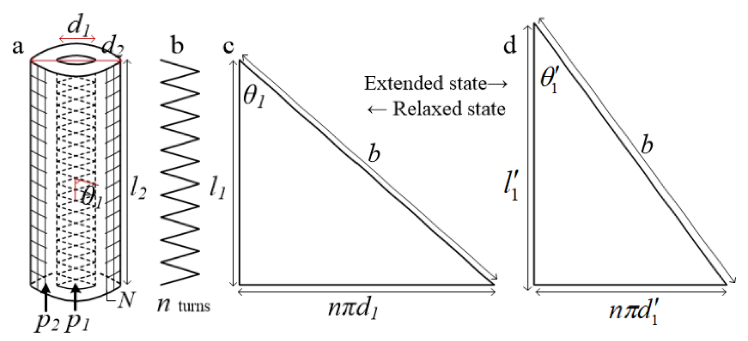
| d1 | Diameter of contractor | 16 mm |
| l1 | Length of contractor | 200 mm |
| θ1 | Braid angle in the relaxed state | 45.2° |
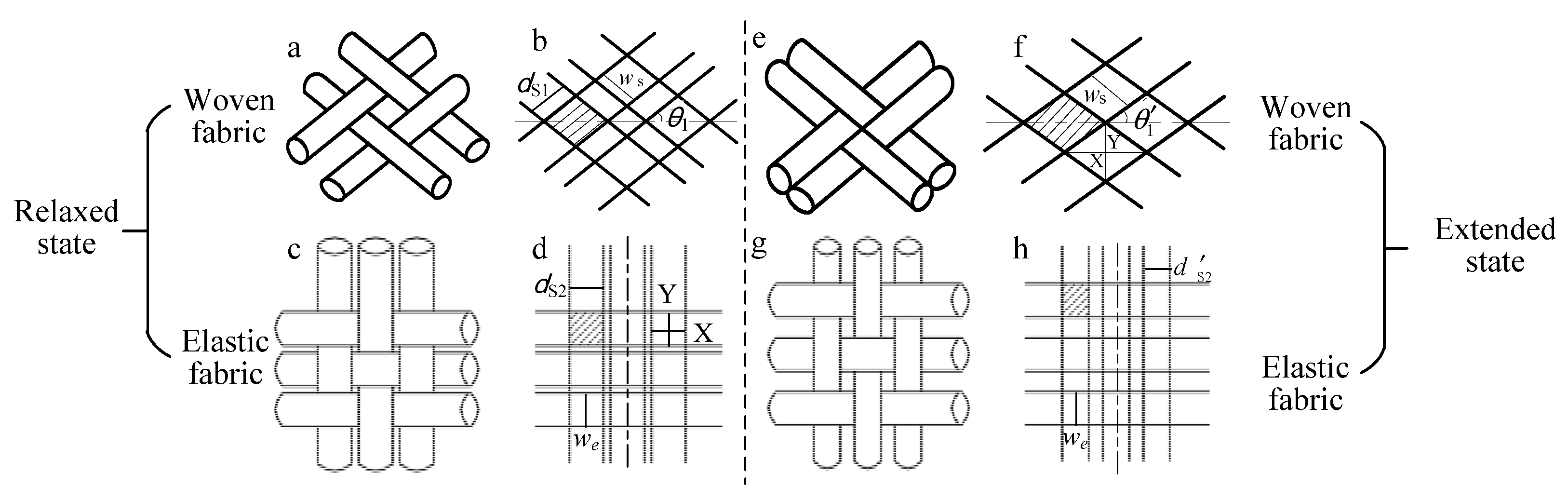
| fS | Friction coefficient of woven fabric | 0.005 |
| fE | Friction coefficient of elastic fabric | 0.25 |
| p1 | Input pressure of contractor | 0~0.3 MPa |
| p2 | Input pressure of extensor | 0~0.3 MPa |
| ε | elongation rate | −0.1~0.2 |
| N | bundles of latex yarns | 60 |
| Experiment No. | ECFA Length (mm) | Contractor P1 (MPa) | Extensor P2 (MPa) | Tensile Stiffness (N/mm) |
|---|---|---|---|---|
| 1 | 200 | 0.14 | 0.05 | 2 |
| 2 | 200 | 0.23 | 0.07 | 10.5 |
| 3 | 200 | 0.34 | 0.12 | 20.3 |
| 4 | 210 | 0.15 | 0.08 | 5.67 |
| 5 | 210 | 0.22 | 0.1 | 12.5 |
| 6 | 210 | 0.32 | 0.15 | 21.2 |
| 7 | 220 | 0.16 | 0.1 | 7.5 |
| 8 | 220 | 0.22 | 0.15 | 13.6 |
| 9 | 220 | 0.28 | 0.2 | 18.67 |
| Experiment No. | Bending Angle (degree) | ECFA① | ECFA② | Stiffness (N/mm) | ||
|---|---|---|---|---|---|---|
| Contractor (MPa) | Extensor (MPa) | Contractor (MPa) | Extensor (MPa) | |||
| 1 | 50° | 0.05 | 0.32 | 0.3 | 0.02 | 1.67 |
| 2 | 50° | 0.08 | 0.35 | 0.25 | 0.14 | 6.5 |
| 3 | 50° | 0.15 | 0.38 | 0.2 | 0.24 | 12 |
| 4 | 40° | 0.02 | 0.23 | 0.18 | 0.03 | 0.5 |
| 5 | 40° | 0.12 | 0.26 | 0.15 | 0.08 | 4.6 |
| 6 | 40° | 0.18 | 0.3 | 0.12 | 0.15 | 8.5 |
| 7 | 30° | 0.03 | 0.1 | 0.08 | 0.02 | 0.25 |
| 8 | 30° | 0.04 | 0.12 | 0.05 | 0.05 | 3.3 |
| 9 | 30° | 0.07 | 0.18 | 0.03 | 0.12 | 5.2 |
Publisher’s Note: MDPI stays neutral with regard to jurisdictional claims in published maps and institutional affiliations. |
© 2020 by the authors. Licensee MDPI, Basel, Switzerland. This article is an open access article distributed under the terms and conditions of the Creative Commons Attribution (CC BY) license (http://creativecommons.org/licenses/by/4.0/).
Share and Cite
Chen, Y.; Zhang, J.; Gong, Y. Novel Design and Modeling of a Soft Pneumatic Actuator Based on Antagonism Mechanism. Actuators 2020, 9, 107. https://doi.org/10.3390/act9040107
Chen Y, Zhang J, Gong Y. Novel Design and Modeling of a Soft Pneumatic Actuator Based on Antagonism Mechanism. Actuators. 2020; 9(4):107. https://doi.org/10.3390/act9040107
Chicago/Turabian StyleChen, Yinglong, Junhao Zhang, and Yongjun Gong. 2020. "Novel Design and Modeling of a Soft Pneumatic Actuator Based on Antagonism Mechanism" Actuators 9, no. 4: 107. https://doi.org/10.3390/act9040107
APA StyleChen, Y., Zhang, J., & Gong, Y. (2020). Novel Design and Modeling of a Soft Pneumatic Actuator Based on Antagonism Mechanism. Actuators, 9(4), 107. https://doi.org/10.3390/act9040107