1. Introduction
Vibration isolation (VI) techniques are generally employed to reduce the vibrations transmitted between a supporting structure (also denoted as base) and a platform, where vibration-sensitive equipment is placed. The vibration propagation occurs via two main scenarios: Scenario 1, the equipment generates vibrations that are transferred to a supporting structure; and Scenario 2, a supporting structure propagates vibrations onto sensitive equipment it supports [
1]. Vibration isolation is achieved by applying an appropriate control force that opposes the vibrations-generated force, by employing isolators that are placed between the supporting structure and the platform(s) to be isolated.
Depending on the method in which this control force is generated, three different techniques can be distinguished: Passive VI (PVI), Semi-Active VI (SAVI) and Active VI (AVI). In both PVI and SAVI, the controlled force is generated passively as a consequence of the relative movement between the supporting structure and the platform [
2,
3]. For PVI, the dynamic properties of the isolator system do not change and, hence, are not able to adapt to changes in the platform and/or supporting structure dynamics. The use of SAVI can mitigate this problem, since the stiffness and/or damping of the isolator system can be varied to adapt to changes in the structural dynamics [
4,
5,
6].
For both PVI and SAVI, VI only occurs for frequencies greater than
times the natural frequency of the isolator (i.e., its cut-off frequency). In addition, a PVI with −40 dB/dec roll-off in the isolation (or rejected) band needs a low damping ratio, which may introduce significant unwanted amplification around its resonant frequency. Nonlinear techniques have been applied to reduce the natural frequency of the isolator system, thereby improving its performance [
7,
8,
9,
10,
11,
12,
13,
14]. The problem of having less than −40 dB/dec roll-off for high frequencies when the damping ratio is reduced can be alleviated by using a spring in parallel with a Maxwell element, i.e., damper and spring in series [
15]. In this approach, the damper tends to be blocked, resulting in a system with two springs in parallel.
AVI presents the following advantages: high damping ratio with −40 dB/dec roll-off in the isolation band, the possibility to reach zero static deflection, robustness to system parameter and operational uncertainties and trajectory tracking capabilities [
16]. These improvements may be required in applications with highly-demanding VI requirements, such as space applications, precision research, manufacturing centres, etc. [
17,
18,
19,
20]. Thus, although the implementation cost of an AVI scheme is higher than PVI or SAVI [
21,
22,
23], their advantages make AVI schemes more attractive in these applications, when compared to PVI or SAVI schemes.
In AVI, in addition to the force generated by the relative movement between the base and the platform, an additional control force is introduced, usually called
active force. This active force is controlled by the adopting suitable feedback or feedforward control techniques [
24,
25,
26]. The application of AVI implies the use of at least one sensor at the platform (feedback) or at the supporting structure (feedforward), as well as a controller and actuator to generate the control force. It is also necessary to deal with the potential problems of real-time signal processing, in particular instability problems when the system is not well modeled and/or is time variant.
If the aforementioned Scenario 2 is considered, the common hypothesis in the classic isolator system design is to consider the supporting structure as an infinitely rigid system compared with the isolator. This assumption is correct when the control force exerted by the isolation system does not significantly affect the base response [
27,
28,
29]. However, this hypothesis is not valid when the movement of the supporting structure is affected by the control force, as occurs in a range of practical cases [
30,
31,
32,
33,
34,
35,
36,
37]. This interaction phenomenon, which can be defined as a hybrid scenario, may change the response of the supporting structure to perturbations, such as force exerted by other activities or displacements. Thus, vibration reduction, which may be achieved by the isolators, can also improve the isolation performance since the absolute VI level may be reduced.
An isolation system including multiple devices using a multi-input multi-output (MIMO) AVI strategy can deal with more complex problems. These MIMO AVI strategies are needed in tasks where multiple isolators are involved, such as multi-degree of freedom systems (e.g., Stewart platforms) or applications where the alignment between equipment is required [
18,
19,
38]. Note that, if the hypothesis of a rigid base is considered, the alignment problem may be considered analogous to obtaining the best isolation performance in terms of platform movement with respect to the supporting structure. Thus, each isolator can be considered as an individual system that does not interact with other isolators or with the supporting structure. However, if the isolators are situated on a flexible supporting structure, the problem must be analyzed from a wider perspective, considering the effect that the isolator makes in the supporting structure response. This effect may involve improvements in the VI performance, as mentioned above, and in the alignment between these multiple devices. Therefore, the model used to design MIMO AVI must consider the supporting structure model, which is excited by both external disturbances and every isolator system, in order improve the performance of the isolation and alignment control objectives.
This paper studies how the control forces exerted by the isolation system may improve performance according to the isolation and alignment control objectives. Thus, under the hypothesis of perturbation forces exerted at the supporting structure, two designs are compared. The first one considers a rigid supporting structure with no dynamic interaction with the isolator system. In this case, the best transmissibility between the accelerations of supporting structure and sensitive equipment is always the best overall solution. The second hypothesis considers a flexible supporting structure with dynamic interaction with the isolator systems. The objective of this paper is to highlight when the best AVI design does not correspond with the best transmissibility, showing the importance of considering this interaction.
The remainder of the paper continues with the general AVI framework, where a model of the isolator system placed on a flexible supporting structure is presented in order to formulate the isolation and alignment problem. Then, this general framework is particularized for a multiple single-input and single-output (SISO) AVI, which feeds back the acceleration measured at the platform of each isolator system. This section also includes the AVI control law employed and the functional used to design optimally the aforementioned real scenario. The next section includes illustrative results obtained with a large set of optimal AVI multiple SISO controllers designed for a large set of supporting structures and isolator systems. This large set of examples are normalized in terms of mass and frequency ratios of both systems. Finally, the main conclusions derived are presented.
2. General AVI Framework
This section defines a general framework where the forces generated by an isolator system together with external disturbance forces can be included into a model of the supporting structure. Thus, the performance of the isolator system, which is defined in terms of isolation and alignment, can be considered as a problem that also involves the supporting structure dynamics. Firstly, the isolator system is analyzed from a base acceleration point of view. The objective is to obtain the acceleration transmissibility between any acceleration measured at the jth isolator and the base acceleration measured at this jth location. Secondly, the base structure is modeled by considering n forces exerted by the n isolators and disturbance forces applied at l nodes of the base structure. Feedback and feedforward AVI can be included in this general model. Thirdly, this real scenario is defined in terms of isolation and alignment objectives.
2.1. Transmissibility Model for the Isolation System
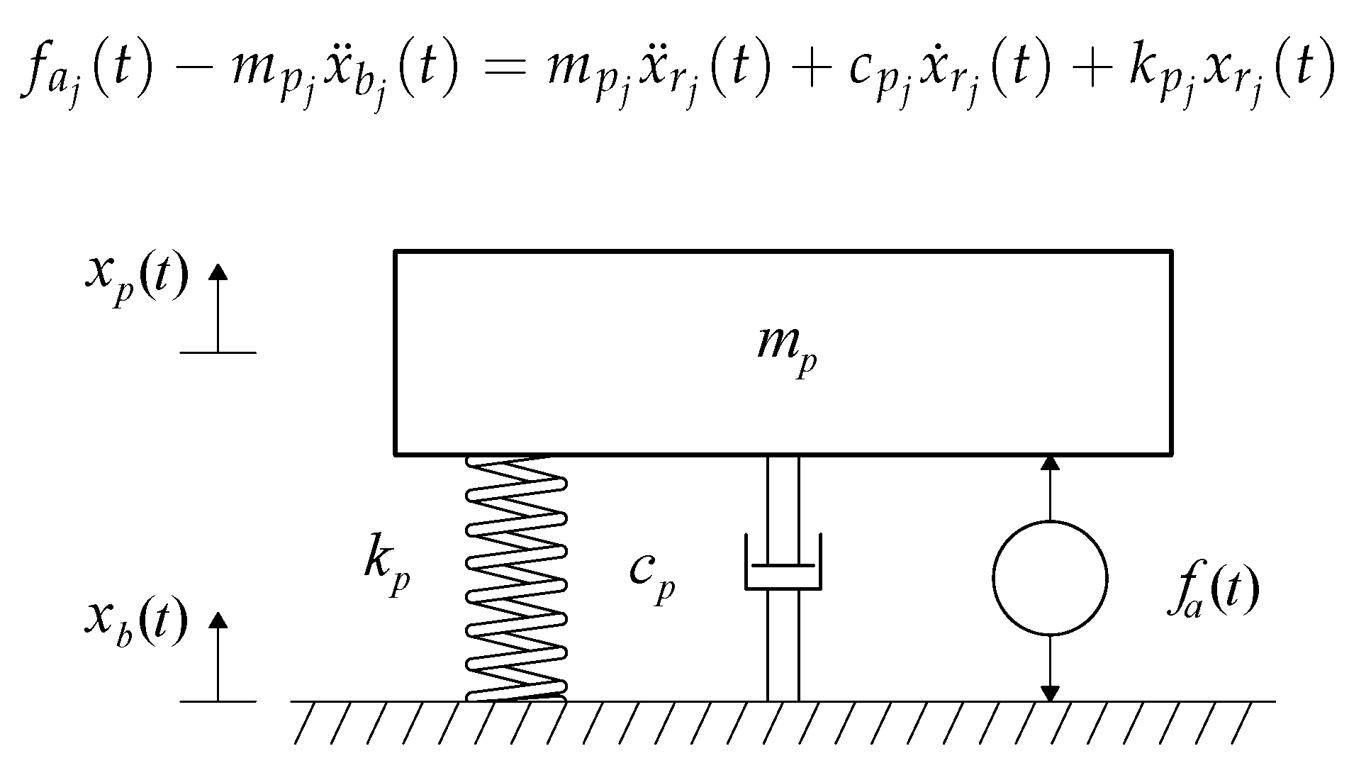
Figure 1 shows the transmissibility model of the a generic isolator
j, such that
. The mass to be isolated is
, which is situated on the platform of the isolator. The dynamic properties of the isolator are modeled with its stiffness
and its viscous damping
. The active force
is obtained either by a feedback and/or feedforward technique, which may consider any variable of the isolator and/or the support. The variables
and
are the accelerations measured at
and at the base, respectively. If the variable
is defined, the differential equation describes the motion of
is expressed as:
It is desired to have a general representation of all modeled isolator systems to formulate the design criteria. Thus, Equation (
1) can be formulated as the following state–space model:
where the vector
and the matrices are hence defined as:
in which
is the natural frequency of the
jth isolator, obtained by
, and
is its damping ratio, obtained by
. Each isolator system then has two inputs, the base acceleration
and the active force
, which depends on the AVI controller utilized.
If Equations (
2) and (
3) are generalized for the
n isolators, the state–space model of the isolators system is:
in which the state variables of each isolator are defined in the vector
; the output vector is
; the system matrix is a diagonal matrix of the system matrices of the
n isolators, such that
diag
; the disturbance input matrix is
diag
; the controlled input matrix is
diag
; the output matrix is
diag
; and the feedthrough matrix is defined as
diag
. The inputs of the system are defined by the vectors
and
.
The model of Equation (
4) can be expressed in the Laplace domain as follows:
in which the variables
,
and
are the Laplace transforms by components of the vectors
,
and
, respectively, and the matrices
and
are formed by the following transfer functions:
where
is a
identity matrix.
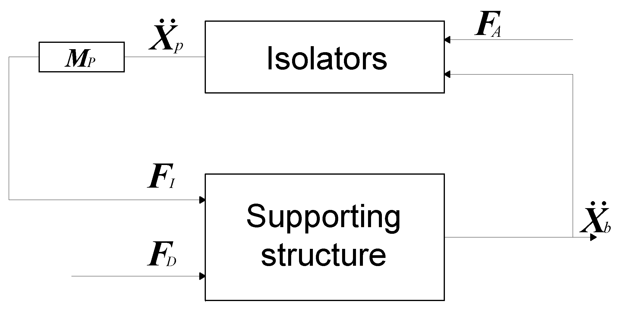
2.2. Supporting Structure Model
Figure 2 shows the model of the supporting structure and isolator system described in Equation (
4). The supporting structure is modeled by considering
n control forces,
, exerted by the
n isolators and
l disturbance forces,
, which can be applied at the isolation locations and/or at other base locations, where
. The outputs of the supporting structure are the accelerations measured at the
n locations of the isolators. The forces exerted by the
n isolators are obtained by multiplying the vector
by the diagonal matrix
diag
.
The state–space equations of the base structure of
m vibration modes can be expressed as follows:
where the matrices
,
,
,
,
and
are defined as:
The vectors , and are the state–space vector, the disturbance force and the forces exerted by the n isolators, respectively. The output vector is . Note that is the acceleration measured in the jth isolator location and is the modal state variable of the qth mode, which is used to define the state vector of the supporting structure.
The terms diag and diag are diagonal matrices formed by the natural frequencies of the structure and the damping ratios. The matrices and are the zero and identity matrices of dimension , while and represent and zero matrices, respectively. is a matrix whose columns are the mode shapes at the disturbance locations, while is a matrix whose columns are formed by the mode shapes of the supporting structure at the isolator locations.
The model of Equation (
8) can be expressed in the Laplace domain as follows:
in which the variables
and
are the Laplace transforms of
and
, respectively, and the matrices
and
are formed by the following transfer functions:
where
is a
identity matrix of the same dimensions as
.
If Equation (
9) is substituted into Equation (
5), the accelerations of the isolator masses are given by:
which depend on the disturbance forces (
) and the active forces (
). This equation is needed to study the influence of the platform acceleration when a non-rigid supporting structure, an AVI and disturbances forces are considered together. Then, the AVI objectives are defined as: (i) transmissibility defined by Equation (
5) (
); and (ii) the alignment between two platforms in the presence of the disturbance force, which can also be defined from Equation (
12) (
). The variables
,
and
are components of the vectors
,
and
, respectively.
2.3. Formulation of the VI and Alignment Problem
The objectives of the AVI defined in this section consider the maximum value of the frequency response functions defined by
and
. Thus, the following variables are defined: (i) the transmissibility between the platform and supporting structure acceleration, defined in this work as:
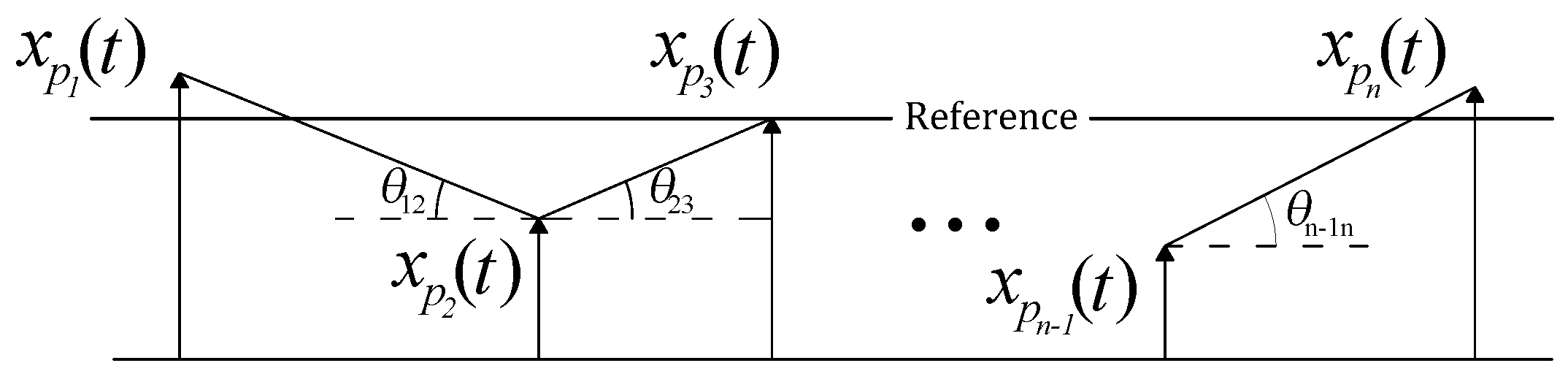
and (ii) the alignment of the isolators located on the supporting structure, which is illustrated in
Figure 3, and defined as follows:
The expression of Equation (
14) is based on the tangent of the angle between adjacent platforms,
. The angle has been considered to be small enough such that
.
As can be observed, both expressions are divided by the number of addends, thus the functional values can be compared independently of the number of isolators and disturbance forces applied on the supporting structure.
The design criterion based on a rigid supporting structure hypothesis considers AVI that minimizes
defined by Equation (
13). The design criterion based on a flexible supporting structure considers the AVI objectives defined by the combination of
and
.
4. Application Example
In this section, the analysis of the VI and the alignment problem is particularized to the case of three isolators placed on a simply supported beam. The numerical results illustrate when the dynamics of the supporting structure must be considered in the alignment problem (i.e., the combination of and ). This section is divided into: (i) system dynamics; (ii) design criterion; (iii) numerical examples for symmetrical and non-symmetrical configurations of the three isolators; and (iv) robustness analysis for isolator parameter uncertainty.
The system configuration adopted here represents a general case study, in which the isolators are situated on the same non-rigid supporting structure. Similar configurations can be found in [
31,
39], in which four actuators are used to isolate the equipment situated on a flexible supporting plate structure. An identical configuration considering only one isolator is also presented in [
40].
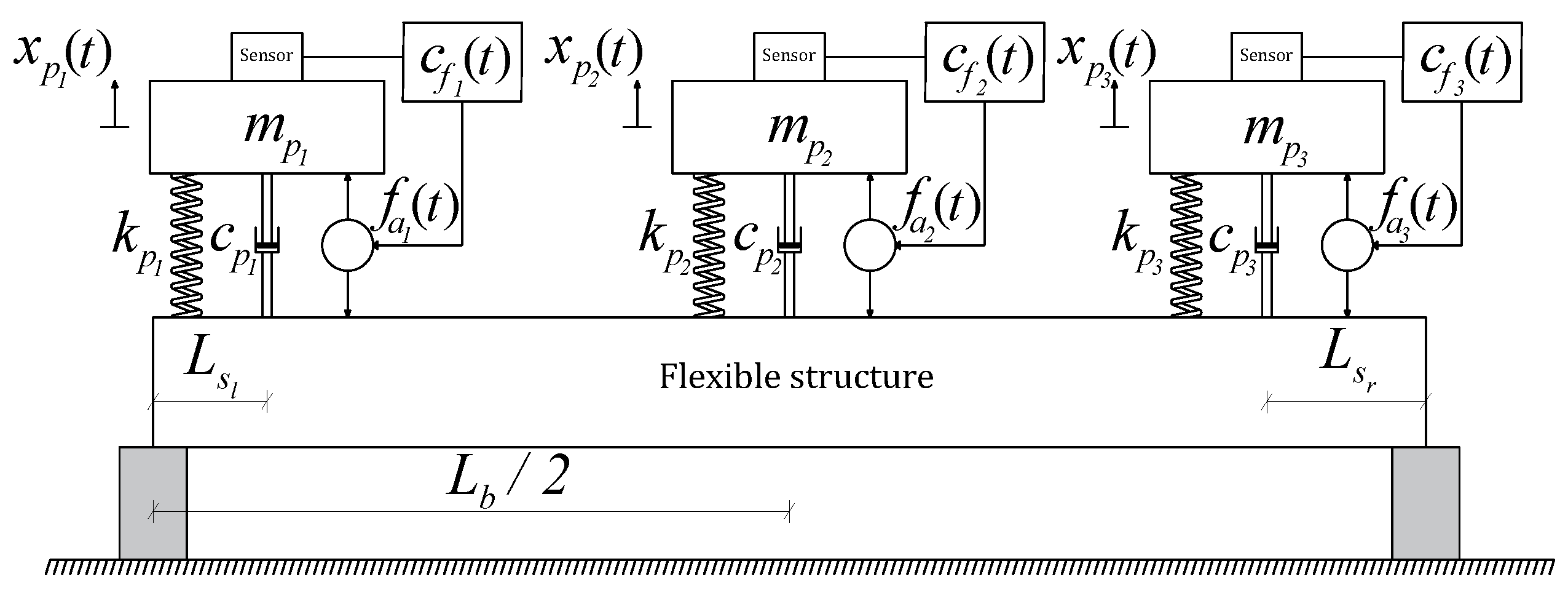
4.1. System Dynamics
The system can be divided into two parts: the supporting structure and the three isolators (
Figure 4). The first is chosen to be a pinned-pinned supported beam. The relevant beam material properties are Young’s modulus (
) and its density (
). The geometrical properties of the beam are defined such that the inertia of the cross-section with respect to the horizontal axis is
and the length between the supports is
.
The
qth mode shape of the beam can be expressed as [
41]:
in which
is a constant that has been chosen to be unity. The frequency of the
qth mode can be expressed as:
in which
is the mass per unit length of the beam. The relationship between the vibration modal frequencies can be defined by considering Equation (
23) as:
, in which
.
The variables and are the distances from the end isolators with respect to the left and right supports, respectively, and they correspond with the location of the isolators and , respectively. The isolator has been considered to be at the mid-span of the beam structure for the symmetrical and non-symmetrical cases. The distances used for the functional are and .
The state–space representation proposed in Equation (
8) is used to model the supporting structure, in which: (i) the number of modes considered for the analysis is
; (ii) the number of inputs of the isolator system (i.e., the number of outputs of the supporting structure) is
; (iii) the considered disturbance forces are at the isolation locations (
) or one force located at
from the left support, which can excite all the considered vibration modes (
); and (iv) the damping is assumed to be constant for all modes, with a value of
, in which
.
The three isolators are considered to have the same dynamic properties (i.e., the values of
,
and
are the same for
). The values of the masses and natural frequencies are defined with respect to the supporting structure model as follows:
where
is the ratio between the isolator mass and the beam modal mass, which is defined as
, and
is the ratio between natural frequency of the isolator and the first vibration mode of the beam. The simulations have been developed considering
.
4.2. Design Criterion
The design criterion is based on finding the optimal gains values
,
and
for each pair of values
and
to minimize the following functional:
where the parameters
and
balance the importance of vibration level reduction for every platform, which is defined by
, and the relative alignment between the isolators, which is defined by
. In this particular example, these parameters are considered as
. Note that: (i) the function
depends on
,
, and
; and (ii) the function
is scaled by
to make
independent of the flexible beam, depending only on
,
and
. Thus, the conclusions can be generalized to any simply supported beam where such configurations of isolator systems are used, simplifying a future experimental validation.
Firstly, if the rigid case is considered, the minimization of the functional value
is simplified to the minimization of
. Thus, the optimal value of
must be as large as possible. To limit this value, this work considers that the maximum damping in this numerical example is one. Thus, the gain
obtained for this damping value, which is denoted as
, is calculated as follows:
where the optimal matrix for the rigid case is defined as
. Secondly, the flexible supporting structure is also considered in order to minimize Equation (
26). The optimal value of
is denoted as
. Thus, the differences in
, which must be greater or equal to one, and
, where each component must be also be greater than or equal to one, are useful to illustrate and quantify the interaction between the supporting structure and isolator system in terms of isolation and alignment objectives. Note that the damping of the transmissibility for
will be always less than or equal to that obtained with
, showing that a worse transmissibility may improve the alignment objective.
4.3. Numerical Results
Since the functional
does not depend on
and
, the value of
is 1 [m], while the modal mass of the supporting structure has been chosen to be 10 kg. The range of the ratios for
and
are defined in
Table 1. The value of each
must be between
and zero.
Two examples are presented: (i) a symmetrical case with
(
); and (ii) a non-symmetrical case with
and
(
and
). In addition, two scenarios are independently studied in order to compare the effect of disturbance force location. The first considers a single disturbance force applied at
. The second considers three disturbances forces applied at the isolator locations. The optimal control gains for each case have been obtained using the Nelder–Mead simplex algorithm [
42] with boundary conditions [
43]. The maximum number of iterations has been chosen to be 2000, with a tolerance on convergence of 10
. Additionally, the stability of the overall system defined in Equations (
9), (
16) and (
17) is verified. Thus, if there are positive real poles, the functional defined in Equation (
26) is penalized and all unstable solutions are discarded.
With the aim of showcasing the effect of uncertainty in isolator dynamics on the VI and alignment performance, a robustness analysis has been conducted. The single force disturbance input case is analyzed for symmetrical and non-symmetrical scenarios, considering variations of 5% and 10% in the dynamic properties , of the mid-span isolator.
4.3.1. Symmetrical Case:
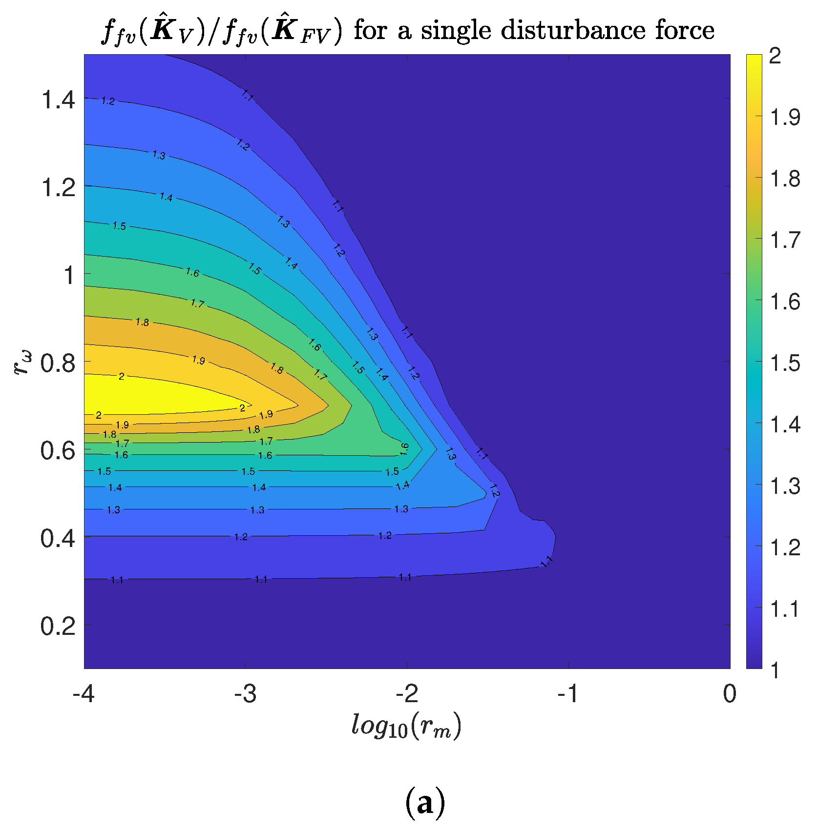
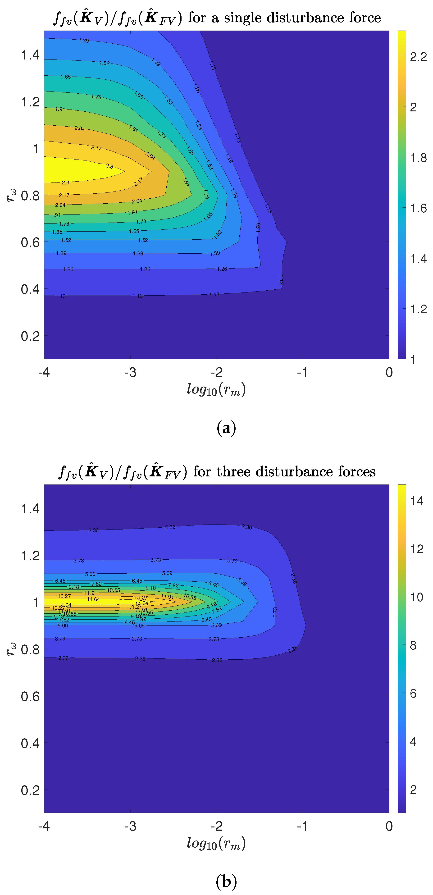
A comparison of the functional
for both optimal control gains
is shown in
Figure 5.
Figure 5a shows the case of a single disturbance force, which is applied at
from the left support, and
Figure 5b shows the three disturbance forces applied at the isolator locations.
The influence of the frequency ratio is much higher than the influence of the mass ratio for the scenario of a single disturbance force. The highest influence region is determined for and low mass ratios. The use of may imply an increment of two times the value of with respect to the use of . It is important to note that, for most of the domain analyzed here, the influence of the dynamics of the supporting structure on the functional value is high. This influence starts to be significant from . In addition, the interval for is between 0.3 and 1.5, when , where the functional varies from 9% to 200%.
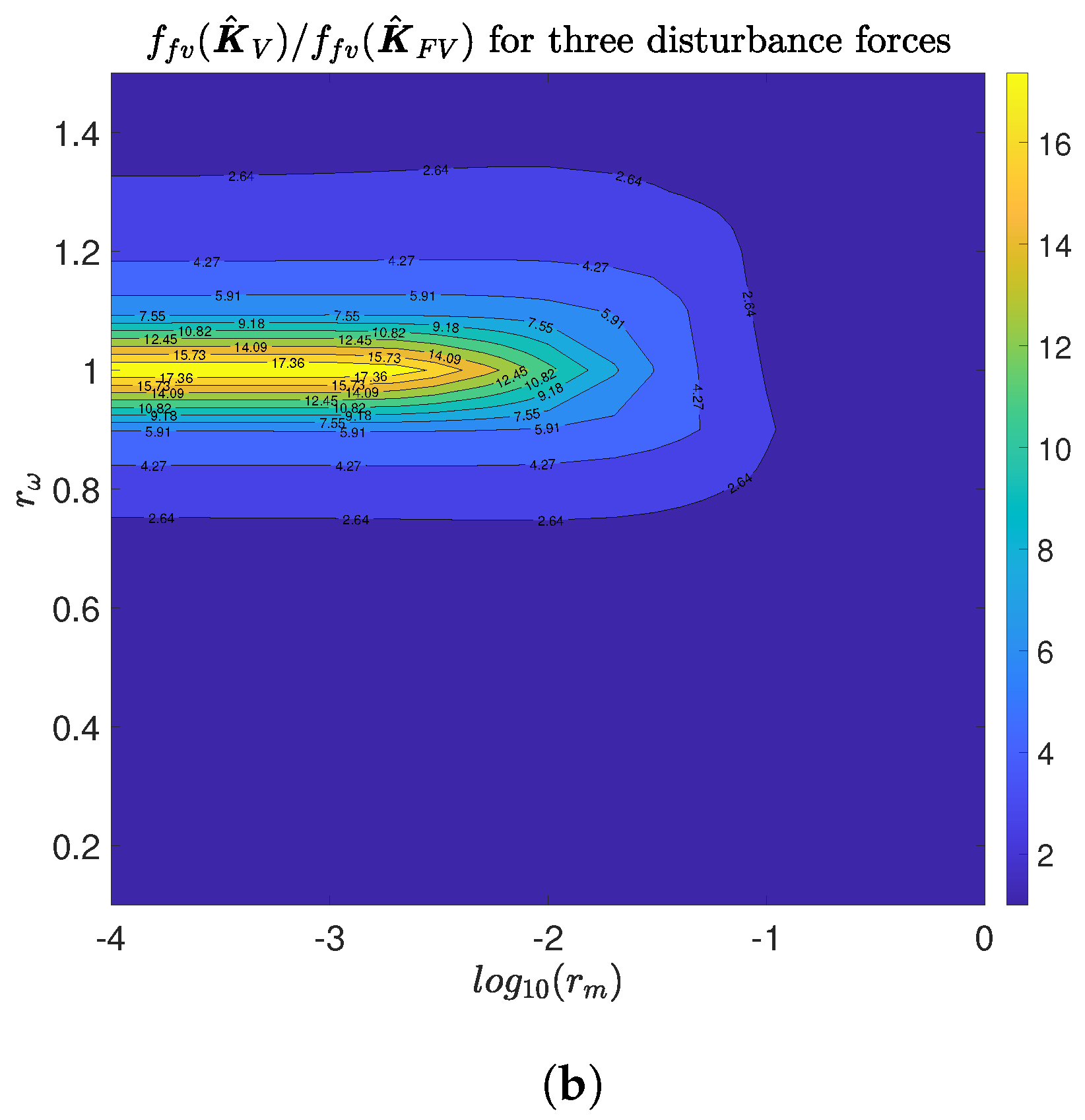
Before analyzing the case of three disturbance forces applied at the isolator locations, it should be noted that the total effect of the force applied at isolators 1 and 3 is null and the force applied at isolator 2 does not excite the second mode. Thus, the second mode of the flexible support does not affect Equation (
26). Therefore, the three gains of the isolators must be tuned to find a trade-off between the transmissibility and the cancellation of the first and third mode. Thus, the improvement must be more important than for a single disturbance force, which excites the three vibration modes. This is evidenced in
Figure 5b, where the ratio
is shown. For most of the region, the use of
implies an increment of the functional value two times higher than the use of
. In addition, if the frequency of the isolators are similar to the first natural frequency of the supporting structure, the influence of the base dynamic on the functional value is higher, reaching an increment of nineteen times higher if
is used. Note that this increment shows that the isolators are working as tuned mass dampers tuned to the resonant frequency of the first vibration mode of the base supporting structure. Note that the difference between an isolator system optimally tuned to damp the first vibration mode respect to other tuned to minimize
, with
, is more significant for low values of
. This justifies that the maximum difference occurs for
.
The functional value
is determined by the control gains. It must be highlighted that, for most of the domain analyzed in this work, the optimal control gain found is not the one that implies maximum damping (
).
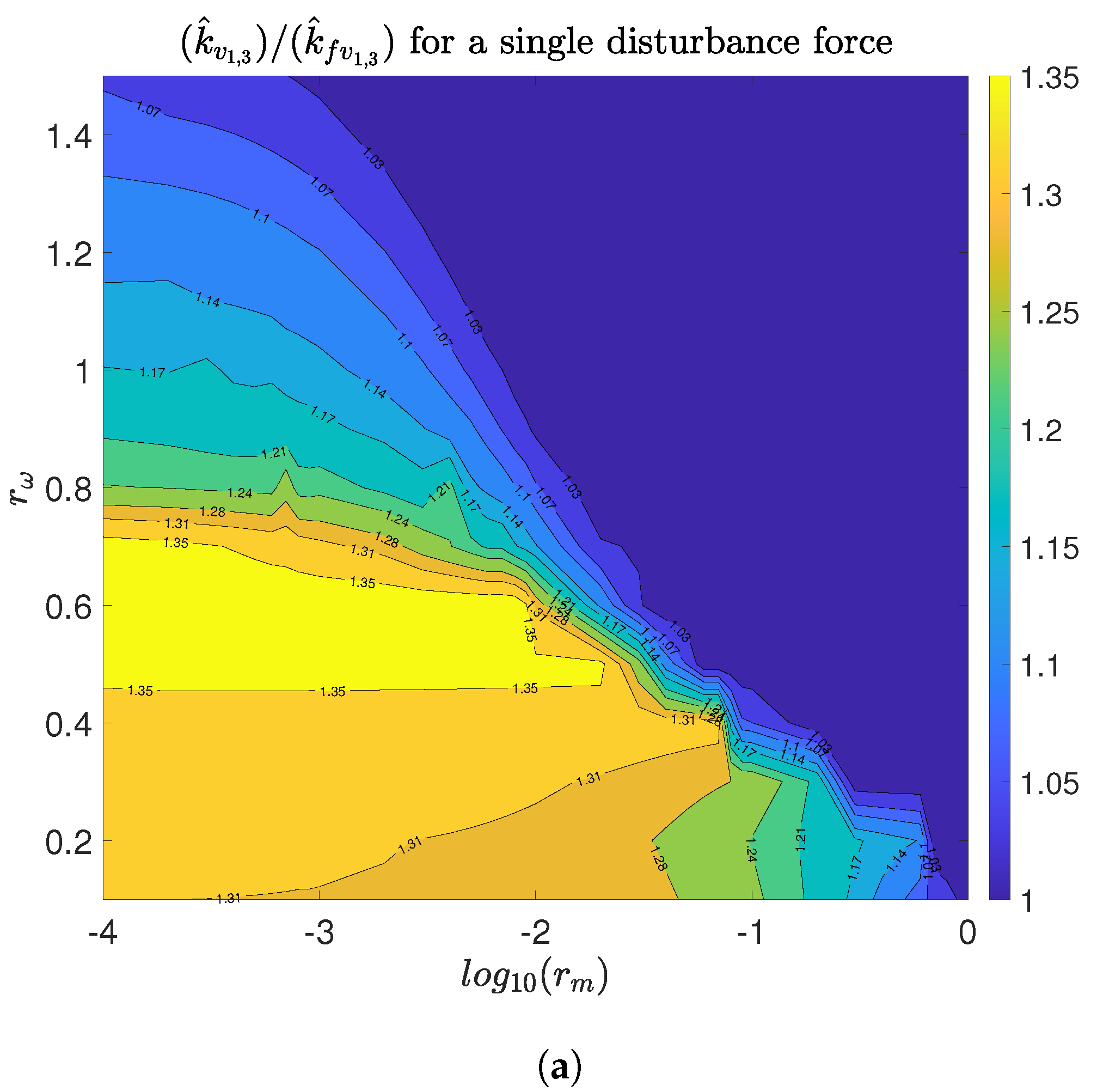
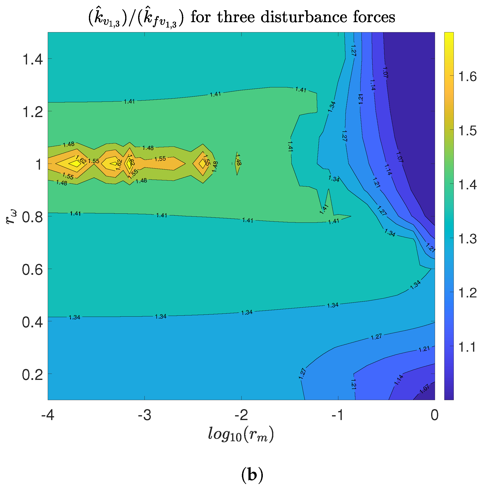
Figure 6a shows the ratio
when a single disturbance force is applied, while
Figure 6b shows the same ratio when three disturbance forces are applied. In both scenarios, the highest gain reduction region is almost coincident with the highest influence region of
. Hence, the compromise between alignment and VI is shown, since considerable reductions in
are achieved with values of
less than one.
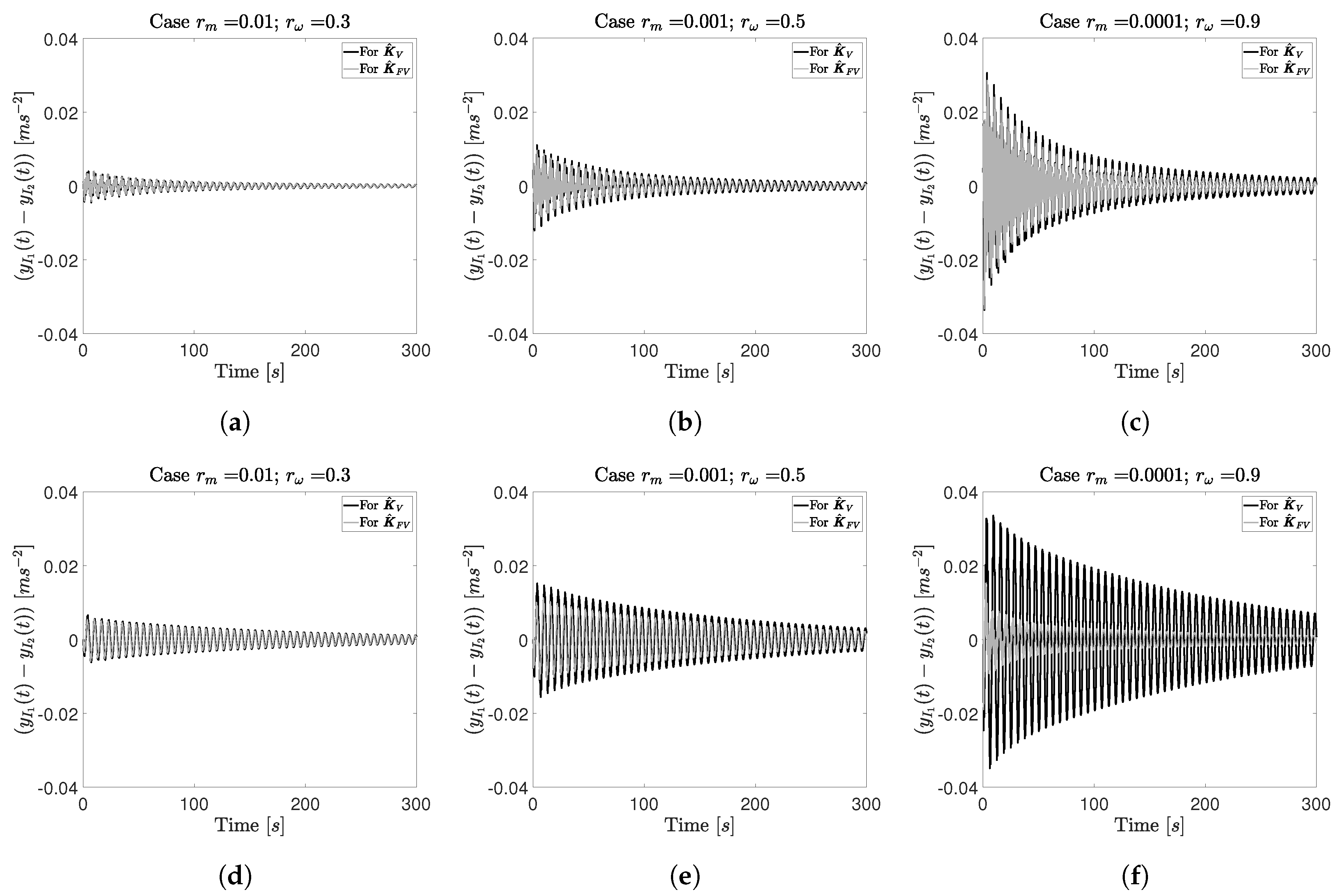
Next, the impulse responses of are compared for three particular cases of and to illustrate the importance of considering the supporting structure dynamics in the control design problem.
For the cases
,
, the ratios
are 1.08 and 1.09 for a single and three disturbance inputs, respectively. A small improvement in the temporal responses can be seen in
Figure 7a,d.
For the cases
,
, which are shown in
Figure 7b,e, the ratios
are 1.35 and 1.37 for a single and three disturbance inputs, respectively. An appreciable change in the time response can be appreciated in these temporal responses.
For the cases
,
, which are shown in
Figure 7c,f, the ratios
are 1.80 and 6.34 for a single and three disturbance inputs, respectively. A high influence of the supporting structure dynamic into the time response can be seen. Note the considerable reduction for the scenario with three disturbance inputs.
Finally, it should be noted that there are two effects. The first one is associated with the level of vibration, which depends mainly on the synchronization of isolators 1 and 2 and their transmissibility. In this case, the response of
is reduced in amplitude but its settling time is not significantly changed (i.e., the damping imparted to the vibration modes is not significant). For example, in
Figure 7b,e, the setting time is slightly increased but the amplitude is reduced. The second one is associated with the damping imparted to the supporting structure, which reduces the settling time of the response
. This can be clearly seen in
Figure 7c,f, as explained in
Figure 5b comments. Therefore, these behaviors, which depend on the interaction between the isolator system and the supporting structure, are not obvious and must be considered when a dual VI and alignment problem is being examined.
4.3.2. Non-Symmetrical Case: and
In this subsection, the case in which the end isolators are located asymmetrically with respect to the mid-span isolator is studied. The distances have been defined to be at the maximum amplitude location for the three first vibration modes, i.e., , . The objective of including this case is to show how the position of the isolators in the supporting structure can also affect the task performance. Note that the contribution of the disturbance forces and the isolators to the vibration modes of the base supporting structure are different with respect to the symmetrical case.
The influence of the supporting structure dynamics on the functional
is analyzed for a single disturbance force applied at
(
Figure 8a). In this case, the first difference observed with respect to the symmetric all case is the change in the highest influence region, which is observed for
. The influence of mass ratios seems to be slightly higher than for the symmetrical case. In addition, the maximum value of the functional ratio
is greater than in the symmetrical case.
In this case, the three disturbance forces can excite the three vibration modes. However, the forces applied to
and
do not excite the second vibration mode significantly in comparison with the first and the third vibration modes. Thus, its contribution is not significant in Equation (
26). In addition, the contribution to the third vibration mode is more significant in Equation (
26), with respect to the symmetrical case. Thus, the improvement in the ratio
is less important in this example, as shown in
Figure 8b. Note also that the maximum influence region is similar to that of the symmetrical case. The highest ratio values of
are lower than for the symmetrical case.
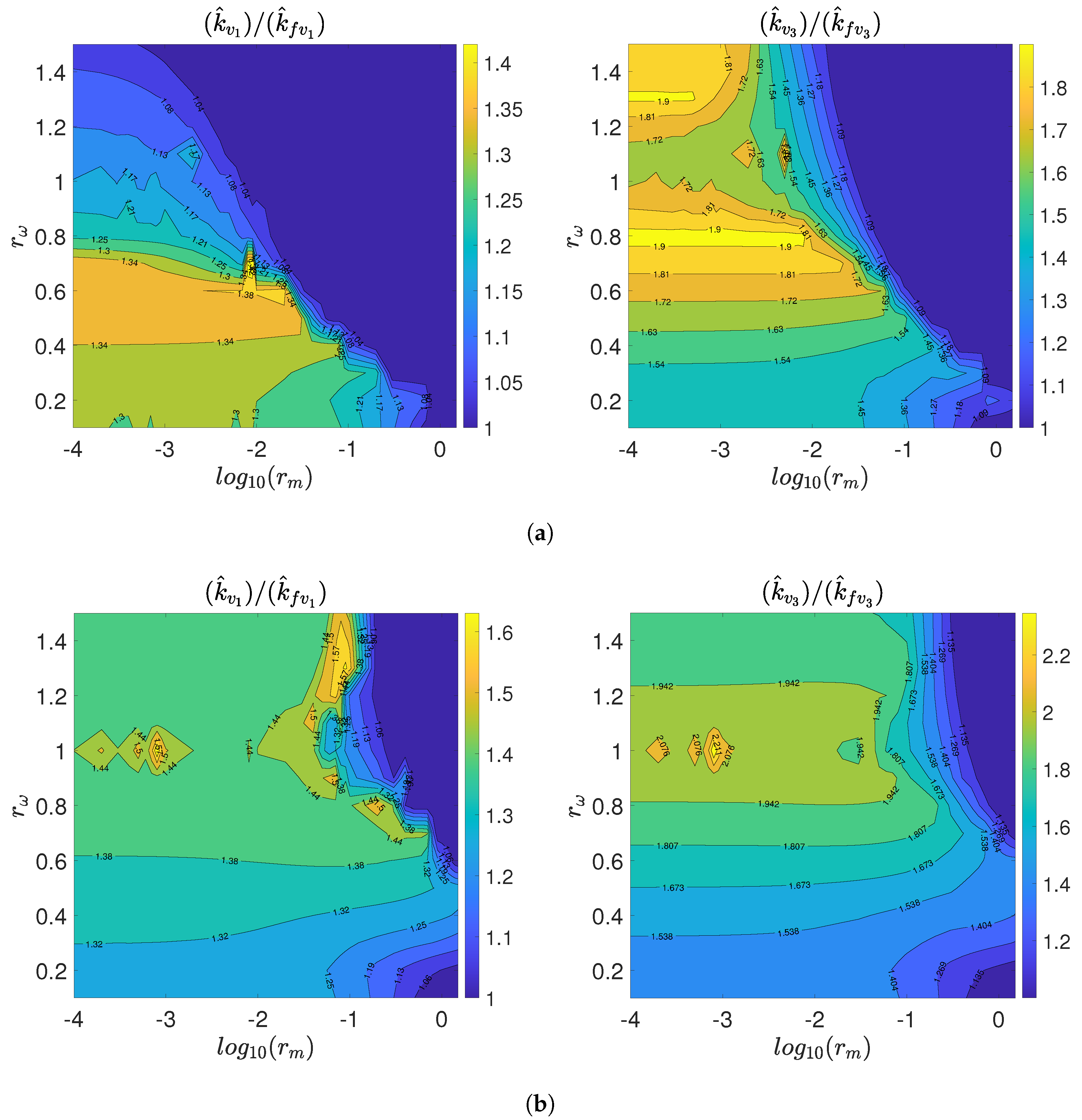
Another difference with respect to symmetrical case is that both end isolators (
and
) have different optimal control gains, since their locations with respect to the mid-span isolator are different. The comparisons between
and
and between
and
are shown in
Figure 9a for one disturbance force scenario. For the left isolator (
), the optimal gain value
can be reduced more than 1.40 times the gain value
. For the right isolator, the optimal control gain considering the supporting structure dynamic
may be reduced more than 1.90 times the gain value
. In both cases, a considerably reduction of the damping ratio is achieved. The same comparisons for the three disturbance force scenario is shown in
Figure 9b. It is observed that the influence of the mass ratio is much higher than for a single disturbance force. For the left isolator, the optimal control gain
can be even 1.60 lower than
. For the right isolator, the ratio
can be higher than 2.
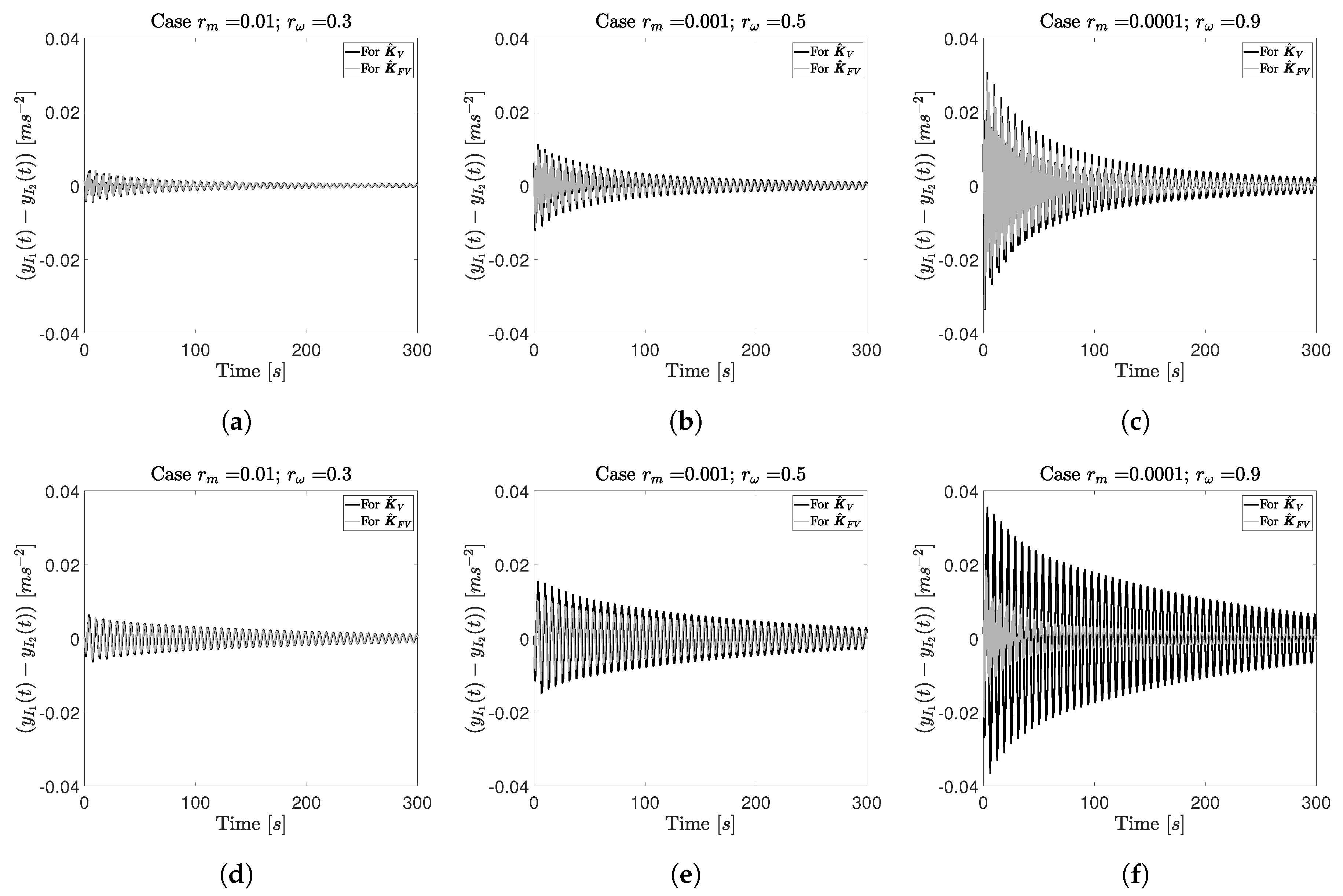
The same strategy of examining impulse response functions of the tangent is followed here to demonstrate the beneficial effect of using the optimal control gain for the alignment problem. The same pairs were used in the symmetrical case are analyzed here.
For the case
,
, the relative alignment between left and mid-span isolators is observed in an impulse response in
Figure 10a,d. For this case, the influence of the supporting structure is not very high, with
for one disturbance input and
when three disturbances inputs are applied. However, it is observed in both temporal responses that the use of
slightly improves the alignment.
For the pair
, the difference of considering
or
is clearly highlighted in
Figure 10b for a single disturbance force, in which the functional ratio
is equal to 1.27. If three disturbance forces are considered, this ratio is equal to 1.29, and the effect in the alignment problem is shown in
Figure 10e. Note that the settling time for the three disturbances forces is higher than for the single disturbance force case.
For the pair
, the value of
is equal to 2.38 for a single disturbance force and 5.28 for three disturbance forces. In
Figure 10c,f, the alignment problem is improved for
.
Figure 10f shows that the settling time is also reduced, and considering the supporting structure dynamics clearly improves the functional value.
4.3.3. Robustness Analysis
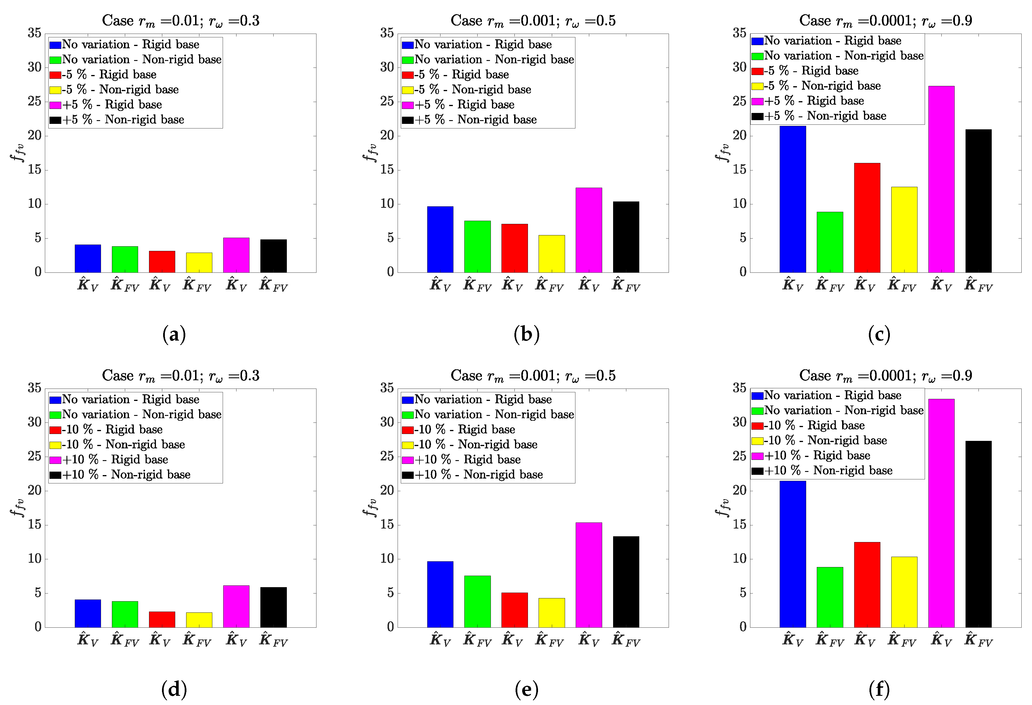
In practical applications, the identified models always encounter uncertainty in model parameters. Moreover, these parameters can be time variant over the operational lifetime and affect to the stability of any adopted AVI scheme. As a result, incorporating adequate robustness to system parameter uncertainty is key to the design and implementation of any AVI scheme. Consequently, to conclude this work, a robustness analysis of the proposed method has been conducted. The nominal values for system parameters—damping ratio and natural frequency of the mid-span isolator ( and )—are both varied by 5% and 10% in each case, and the AVI performance, alignment and stability are quantified. The first main conclusion of this analysis is that the proposed AVI scheme is always stable across the uncertainty zone. The second conclusion is that can vary significantly when and change. Additionally, the value of for the rigid base is either equal to or greater than that for the non-rigid base (improved performance).
The three parameter value sets for and for symmetrical and non-symmetrical cases and a single disturbance force analyzed are: (i) , ; (ii) , ; and (iii) , . Note that the parameter varies when changes. The value of depends of and . Therefore, the nominal case is not the optimum for this robustness analysis. In other words, the values for can be reduced when the parameters and change.
Figure 11 shows the effect on the VI and alignment performance for the symmetrical case. For the first case, the robustness analysis is shown in
Figure 11a,d. It is observed that, if the value of the parameters of the mid-span isolator are reduced, the response is improved and vice versa. This is because the control gain limits are not changed. However, in both cases, considering the dynamics of the supporting structure improves the VI and alignment performance.
Similar behavior is encountered for the second case, as shown in
Figure 11b,e. As expected, for a higher variation in the dynamic properties of the mid-span isolator, the performance is more different respect to the ideal case ( no variation). It can be observed in the the third scenario (
Figure 11c,f) that, although the functional value is high for the ideal case (no variation), considering the dynamic of the supporting structure improves the performance even though the controller is not designed considering uncertainty in the dynamic properties of the isolator.
For the non-symmetrical case, similar behavior is observed for the first case (see
Figure 12a,d). As the control gain limits are maintained, performance improvement is seen when parameter values are reduced when compared to the nominal case. The performance of the VI and alignment performance is worsened compared to the ideal case when the parameters are increased. However, in both cases, considering the dynamics of the supporting structure improves the response.
For the second (
Figure 12b,e) and third (
Figure 12c,f) cases, similarity to the symmetrical case is found, hence showing the importance of considering the dynamic of the supporting structure.


