Abstract
Template-based and additive manufacturing techniques have demonstrated some fabrication routes for creating pneumatic soft actuators. However, as the complexity and capability of the actuators continue to develop, the limitations of these approaches are becoming evident. These include difficulties for design variations, process speed and resolution, material compatibility and scalability, which hinder and restrict both the possible capabilities of the technology and its transition from research to industry. This body of work presents a computer-controlled, maskless manufacturing process with a different approach to allow for high-speed, low-cost and flexible creation of pneumatic soft actuation networks comprising multi-material construction. This was investigated through a bespoke fabrication platform that provides computer-controlled localised plasma treatment to selectively modify the chemical behaviour on the surface of silicone and polyethylene terephthalate (PET) bodies. The altered surface chemistry facilitated selective bond formation between the treated parts of the surface and, consequently, greater design variation and control over the pneumatic chambers that were formed. Selective treatment patterns allowed nonlinear pneumatic chamber designs to be created, and the strength of bonded silicone structures was shown to facilitate large deformations in the actuators. Furthermore, the different interactions between the plasma and silicone were leveraged to achieve feature sizes of <1 mm and treatment speeds of 20 mm2 per second of exposure. Two multi-material pneumatic soft actuators were then fabricated to demonstrate the potential of the platform as an automated manufacturing route for soft actuators.
1. Introduction
Soft robots use compliant and elastic materials throughout their structure. The inherent properties of the constituent materials result in fundamentally different behaviour compared to their rigid counterparts. This has led to the development of novel devices such as locomotive robots capable of navigating through passages smaller than their original shape [1], robots adept at manipulating fragile or pliable objects [2,3,4,5] and wearable assistive devices to aid the rehabilitation of joint mobility [6,7,8,9], to highlight a few. Key to their performance was the mechanism by which force was produced. Several examples of soft actuators have employed phenomena such as phase change materials [10], mechanical tension [11] or electrostatic forces [12] to initiate motion. Utilising pneumatic power offers higher force production and displacement, rapid response times and more conventional operation. Pneumatic actuators consist of a deformable body, which has a sealed air cavity that can be inflated to induce actuation. The magnitude of the motion can be controlled by the pressure supplied to the cavity, while the direction is dictated through anisotropic stiffness. The materials involved however are difficult to shape into the geometries and structures desired in the developing field applications, which has led to advancements of the fabrication tools and methods over recent years.
Casting liquid elastomers into moulds that then solidify in the presence of a curing agent or catalyst is one the simplest and most popular methods used to realise soft structures [13,14,15]. This approach is compatible with many relevant materials and can be carried out with limited equipment while scaling well to high-volume production; however, there are several drawbacks surrounding the practicality of the process. In situations where designs are iterated, or applications that require personalisation of dimensions such as joint mobility rehabilitation, progress is slowed, and waste is increased. Using high resolution moulds such as those produced by soft lithography [16] or high accuracy 3D printers [13] exacerbate this due to being expensive or slow, or requiring specialist facilities. Aside from this, moulding also limits the geometry of the actuator and restricts it to a single material, which makes it only suitable for the simplest of actuators. Utilising a digitally driven approach, such as direct 3D printing, that directly deposits or bonds soft material removes the need for moulds, so it can save time, increase geometric freedom and incorporate multiple materials. A variety of commercial 3D printing techniques have been exploited including fused deposition modelling, stereolithography, selective laser melting, material jetting and direct ink writing. These processes have provided examples of some of the most advanced actuators to date, demonstrating multiple materials to achieve unique motion [17] or integrated sensing [18]. Detailed reviews of these processes are available elsewhere [19], but to summarise, these techniques face limitations surrounding resolution, speed, materials and scalability. Many of these limitations are artefacts of the fundamental principles of the techniques. For example, using a nozzle to control the deposition of material introduces an inverse proportionality between speed and resolution that cannot be overcome by technical advances. As a result, approaches outside of 3D printing have also been explored. Methods of selectively bonding solid soft materials offer an effective method that bypasses the limitations that are presented with direct 3D printing. There are two predominant approaches for bonding between soft materials, i.e., either using an adhesive or by chemical bond formation [20]. The adhesive choice however is limited to uncured liquid elastomers to achieve strong bonds, which when used selectively encounter the same issues as 3D printing because the deposition of the liquid elastomer adhesive must be controlled. In contrast, chemical bond formation does not require any material deposition, but rather a modification of the surface at a molecular level to facilitate covalent bond formation between two different material surfaces. Plasma treatment in particular has proven highly successful at bonding silicones, which are one of the most common soft material groups used for soft actuators, to a range of materials including other silicones, various plastics and metals [21]. In this method, the surfaces to be bonded are oxidised by highly reactive oxygen species such as those created by UV lamps or plasma discharges. This oxidation then leads to bonding between the silicone surfaces when two oxidised surfaces come into contact [20]. In order to bond to non-silicone plastics, the material must be submerged in a silane solution after oxidation, which implants silicone-like chemical structures on the surface [22]. The resulting bond between the non-silicone plastic and the silicones can withstand pressures of 1000 kPa and has been demonstrated to be suitable for pneumatic soft actuators [23]. In that prior work, selectivity of bonding was introduced by using an ink-jet printer to mask areas of the plastic before surface treatment, preventing bonding. This demonstrated a method that could fabricate pneumatic soft actuators in hours, with greater material freedom, higher resolution and effective up-scaling. However, using a printed mask restricts not only the size of actuators but also limits it to planar, single-layer designs unless a gantry-mounted print head were to be used, which would dramatically increase the fabrication time.
In this work, a new approach to achieving selective bonding of silicones to non-silicone plastics is presented that utilised a localised plasma discharge to selectively oxidise their surfaces, facilitating complex pneumatic designs to be created with very high bond strength. By localising the treatment, the restrictions on substrate shape and size were removed, and processing times were reduced due to eliminating the need for a masking step.
2. Materials and Methods
2.1. Selective Plasma Treatment Platform
The manufacturing platform that was designed and created in this research is summarised in Figure 1. Plasma was generated using a commercially available plasma jet (Piezobrush PZ2, Reylon Plasma GmbH, Regensburg, Germany) which produced a localised source of the reactive species responsible for the surface modification. This featured a nozzle that guided a gas flow over a high-voltage electrode to generate the plasma.
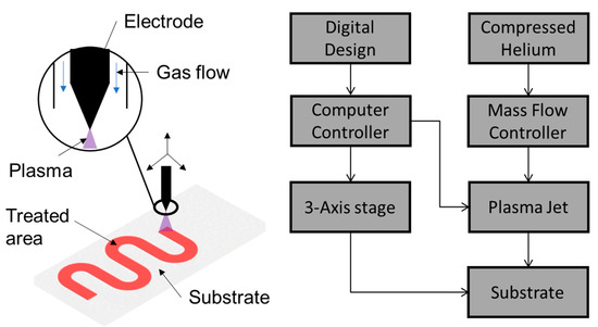
Figure 1.
Selective plasma treatment platform overview.
Helium was supplied using a compressed gas bottle (UN 1046, BOC UK, Guildford, United Kingdom). The mass flow rate of the gas was regulated using a manual flow regulator (BOC). A cartesian 3-axis actuation platform with plasma jet mounted on the Z-axis was controlled using a VK8200/SP (Velleman, Gavere, Belgium) control board. To synchronise and control the plasma jet operation itself, a relay module was connected to an external power supply and the control board. Using Repetier (Version 2.1.6 Windows, Hot-World GmbH, Willich, Germany), the motion and state of the plasma jet could be controlled simultaneously using g-code. A post-processing script was used to modify the g-code to include the commands for the plasma jet so that coding derived by computer-aided design and manufacturing (CAD/CAM) tools could be used to operate the platform. The exposure time, offset distance and gas flow rate could all be manipulated to control the interaction of the plasma with the substrate. For all treatments, the plasma jet was operated while stationary in discrete bursts at intervals along the tool path to avoid overheating. A constant offset from the substrate of 3 mm and a helium gas flow rate of 1 L/min was used
2.2. Material Processing
Bonding was carried out between Ecoflex 00-50 (Bentley Advanced Materials, Kidderminster, United Kingdom) and 100 µm thick polyethylene terephthalate (PET) sheets (Write-on transparency film, Office Depot UK Ltd., Leicester, United Kingdom). The difference in the stiffness of the two materials was ideal for creating a bending motion in pneu-net style actuators. First, the Ecoflex parts A and B were mixed in equal weight before being degassed in a centrifugal mixer degasser (ARE-250, Thinky U.S.A Inc., Laguna Hills, CA, USA). Once degassed, the elastomer was poured into a mould and degassed again under vacuum of 0.02 bar for 2 min. Finally, it was cured at 45 °C for 30 min. The PET sheets were then treated using the selective plasma treatment platform according to the desired pattern and then submerged in a 1% concentration solution of 3-aminopropyltriethoxysilane (APTES, Merck Life Science UK Ltd., Gillingham, United Kingdom) for 20 min before being removed and dried with compressed air ready for bonding. While the PET was in the APTES solution, the Ecoflex layer was plasma treated with a corresponding pattern. Once treatment was complete, the dried PET and treated Ecoflex were aligned and placed in contact manually; no additional equipment was used to align layers or apply pressure. Some degree of bonding took place instantaneously, but for the bonding to complete, the samples were left at room temperature for 2 h. Care was taken throughout the process to prevent surface contamination that could have interfered with treatment or bonding. This procedure was used for all samples.
2.3. Plasma Treatment
In order to confirm that the surface of the Ecoflex underwent chemical modification, three metrology methods were employed. First, optical emission spectroscopy was carried out on the plasma discharge using a Flame Extended Range Spectrometer (Ocean Insight, Orlando, FL, USA). To accomplish this, the probe was placed 10 mm away from the discharge laterally and 3 mm below the nozzle tip such that the discharge was being analysed at the point of contact with the substrate. This provided the relative intensity of electromagnetic radiation wavelengths emitted and was used to identify the specific species that are directly created. Second, X-ray photoelectron spectroscopy (XPS) was used to analyse the elemental composition changes that occurred due to the treatment for Ecoflex only. This was carried out on an EnviroESCA device (Specs Group GmbH, Berlin, Germany) by the Bragg Center for Materials Research at the University of Leeds, Leeds, United Kingdom. Finally, the surface was inspected with a microscope (BX53M, Olympus UK & Ireland, Southend-on-Sea, United Kingdom) to identify any visual changes. As the PET undergoes a chemical treatment with APTES, with a known modification effect, the XPS was only carried out for Ecoflex.
2.4. Bonding Characterisation
Two different approaches to selective bonding were studied. They were made possible with this apparatus, and are described in Figure 2. These concerned selective surface treatment to encourage areas of bonding (termed Approach 1) or selective surface treatment to prevent areas of bonding (termed Approach 2). This was intended to explore the effectiveness of the bonds created, and to establish if different methods may be more appropriate according to the scale and design of the pneumatic actuator to be created. Approach 1 is similar to that which was undertaken in previous studies [22,23], with the substrates being treated such that sufficient oxygen is chemically added to the surfaces to cause bonding. However, as a localised plasma source was used, selectivity could also be achieved by overtreatment (Approach 2). This approach intentionally treated the Ecoflex surface to form a ceramic silica layer, which other works stipulate to be in the order of 5 nm thickness [24,25], that did not bond to PET. This is possible because a point source of plasma varies in reactive species concentration radially away from its centre, and as a result so does the degree of treatment. Due to this, zones of silica were formed as well as zones of treatment for bonding depending on the exposure level.
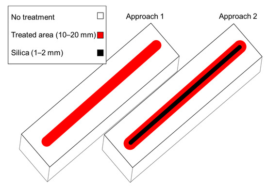
Figure 2.
The two different approaches to selective bonding. Dimensions of each region depend on the exposure level.
The level of treatment required to form silica was much higher than that to facilitate bonding, and so it was first formed directly under the discharge where the concentration of reactive species was highest. This meant that the region where silica formed was an order of magnitude smaller than that of the treated area, making Approach 2 capable of fabricating actuators with smaller features at higher resolutions compared to Approach 1, but with a corresponding increase in processing time. Due to this, the resolution and uniformity of each approach were characterised separately. The bond strength was only investigated for Approach 1 as this used lower treatment times with less oxygen implanted on the surface, and so gave a minimum bond strength. To investigate the resolution, uniformity and bond strength of Approach 1, a 30 × 60 × 0.1 mm PET sheet and a 30 × 60 × 3 mm Ecoflex sheet were bonded entirely across their centres following the bonding procedure outlined in Section 2.2 (Figure 3A). The plasma treatment was conducted with a single pass at treatment intervals of 1mm with three different exposure levels, namely 0.5 s/mm, 0.75 s/mm and 1 s/mm. After bonding, samples were inspected with the bond width measured across the bond before each underwent a 180° peel test (Figure 3B). Three samples were created for each treatment level, with each sample undergoing both bond width inspection and peel testing. Having then found the most suitable treatment level to be 1s/mm, three separate sealed chambers for inflation were made to directly test how suitable the bonding was for the fabrication of pneumatic soft actuators (Figure 3C). This consisted of a 50 × 50 × 0.1 mm PET sheet bonded to a cast 50 × 50 × 3 mm Ecoflex sheet that featured an air inlet. The tool path is illustrated in Figure 3C. These were then inflated using a closed-loop pressure-controlled air supply unit (Fisnar DC 100, Ellesworth Adhesives Europe, Glasgow, United Kingdom) until failure, recording the maximum pressure and failure mechanism. The resolution and uniformity of Approach 2 were investigated by treating Ecoflex samples with a 50 mm line at treatment levels 1.2 s/mm−1.45 s/mm with an interval of 0.1 mm between each treatment. After treatment, samples were strained until they produced cracks in the silica layer and then measured at 10 positions across the treatment path in a relaxed state using a microscope (Olympus BX53M).
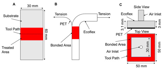
Figure 3.
(A) Sample design to test bond resolution and width. (B) 180° peel test. (C) Sample design for bond pressure testing.
2.5. Fabrication of Actuators
Using parameters derived from experiments in Section 2.3 and Section 2.4, two demonstrator actuators were fabricated, one for each selectivity approach. The designs and treatment profiles for each actuator are displayed in Figure 4. Additionally, Video S1 (Supplementary Materials) shows the fabrication of the actuator made via Approach 1. Both the Ecoflex and PET layers were treated using these profiles. Approach 1 used a 2 mm thick Ecoflex layer to mitigate the reduced actuation speed, which resulted from a large inflation volume by reducing the pressure needed to induce deformation. Approach 2 used a 3 mm Ecoflex layer as the inflation volume was much smaller. In Approach 1, the area to be bonded was directly exposed to the plasma, whereas in Approach 2 this was the area not to be bonded via silica formation. Once fabricated, the actuators were marked with red ink along their edges to aid with visual tracking of the deformation and inflated up to 16 kPa and 63 kPa for Approaches 1 and 2, respectively.
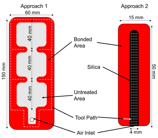
Figure 4.
Design of the actuators fabricated by each approach.
3. Results
3.1. Plasma Treatment
The emissions from the plasma discharge were dominated by nitrogen and hydroxyl species, as can be seen in Figure 5. The emissions from 200−300 nm indicate that NO was formed [26], while the various peaks from 300−450 show that N2 transitions occurred [27]. The peak at 308 nm confirms OH species were present. The peaks at 477.1 nm, 587 nm and 667 nm show that helium transitions [27] took place. It is clear from this spectrum that, although only He was supplied to the plasma jet, various species were subsequently created due to the interactions with atmospheric air. It is important to note that no emissions were detected at 777 nm or 844 nm, which would indicate the presence of atomic oxygen [27].
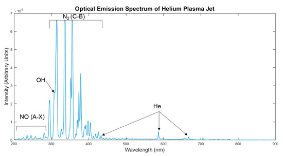
Figure 5.
The spectrum emitted from the plasma discharge.
However, this technique can only detect species that undergo electron energy level transitions, and so species created by the subsequent reactions, such as ozone, could not be detected but could interact with the substrate. As such, it is more important to look at the effect on the substrate, shown by the XPS analysis results in Table 1.

Table 1.
XPS results from the treatment of Ecoflex 00-50.
This shows that, despite the nitrogen-dominated discharge, the oxygen content increased with treatment time, whereas the carbon content decreased. This is likely due to downstream interactions that created reactive oxygen species and this trend correlates with those reported elsewhere [28]. This confirmed that plasma treatment was appropriate for the bonding as no nitrogen was detected on the surfaces that would have interfered with the bonding. Notably, at a treatment time of 0.5 s, the carbon content increased by 2.53% and the silicon content decreased by 2.73%, which opposes the trend of the rest of the data and the secondary data available in the literature, and as such this is unlikely to be a result of the plasma treatment. These results were intended to be purely qualitative as the spatial resolution for the XPS analysis was too low compared to that of the treatment to calculate concentrations of oxygen across the treated surface or draw any further conclusions about the relationship between treatment time and oxygen content. At a treatment time of 1.5 s, there was a prominent change in the Si:C ratio, which indicates overtreatment and silica formation. This was confirmed by inspection under a microscope, where clear cracking of the surface can be seen in Figure 6. No silica formation was observed under microscope inspection for either a 0.5 s or 1 s treatment time.
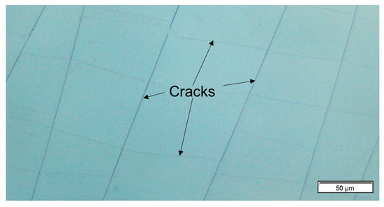
Figure 6.
Image of cracked Ecoflex surface 10× magnified after 1.5 s plasma treatment.
The optical emission spectrum suggests that the proportion of reactive oxygen species was relatively low. Increasing this could lead to shorter treatment times as more oxygen would react with the silicone surface per unit time. One method of doing this is by including oxygen in the feed gas [29]; however, this would require integrating additional mass flow controllers and mixers. As the XPS shows that oxidation of the surface was already occurring, and in fact overtreatment was occurring within 1.5 s, this sort of modification would only provide a fractional reduction in the overall process time.
3.2. Bonding Characterisation
The bond uniformity data gathered from the samples described in Section 2.4 (Figure 3A) are presented in Figure 7. They show that the process was inconsistent for treatment levels 0.5 s/mm and 0.75 s/mm with bond widths ranging from 11.9 mm to 14.6 mm and from 15.6 mm to17.6 mm, respectively. For pneumatic soft actuators, this level of variation would be unacceptable as it would lead to unintended deformation when inflated. At a treatment level of 1 s/mm, however, this range was improved to 19.8−20.4 mm. When designing a pneumatic actuator to be fabricated using this method, this situation must be considered. For example, if an actuator with a target chamber width of 4 mm was fabricated using the approach, then the resulting chamber would vary in width between 3.4 and 4.6 mm. This would produce actuation behaviour different from that which the actuator was designed for. Therefore, this approach is only suitable for large actuators where the impact of the variability is minimized.
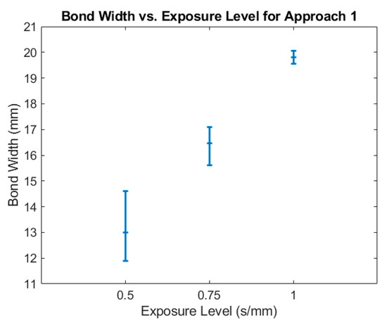
Figure 7.
Measured bond width at 3 exposure levels.
In the 180° peel tests, all samples from every treatment level underwent failure in their Ecoflex layer, not at the bond suggesting suitable bond strength for pneumatic soft actuators. This was then further corroborated by inflating the chambers described in Section 2.4. (Figure 3C), made using a 1 s/mm treatment level. All samples inflated failed in the Ecoflex layer at pressures ranging from 34 to 36 kPa. An example of one of these samples just prior to bursting can be seen in Figure 8. While this confirms that the strength of the bond is suitable to operate pneumatic soft actuators, it does not address any fatigue failure mechanisms that may be incurred through repeated cycling of the actuators, which requires further study. This will need to be studied as part of a further process and device development.
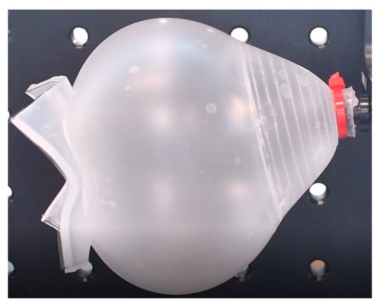
Figure 8.
Pressure test sample inflated to 33 kPa.
The results from Approach 2, selective bonding by overtreatment, showed a much higher resolution than that of Approach 1. Feature sizes ranged from 0.94 mm to 2.18 mm and were controllable with exposure level, as seen in Figure 9.
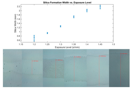
Figure 9.
Measured width of silica formation at 6 exposure levels with examples of each.
The silica formation width became uniform at treatment levels of 1.25 s/mm and above where deviations from the mean did not exceed 0.1 mm; however, below this exposure level the silica formation width was highly variable and unsuitable for the fabrication of pneumatic soft actuators. This level of variability improves in Approach 1 by more than 3 times, making it more reliable for the fabrication of small-scale actuators. The two approaches demonstrated here represent a highly adaptable process that is capable of producing both 20 mm features quickly and sub −1 mm details without a modification to the hardware. These capabilities cannot be found in any other digitally driven technique to date such as 3D printing. As many applications often have features ranging across these scales, this technique is in a unique position where it could reduce the complexity, time and cost of fabricating many of these devices. The feature sizes achieved here were larger than those made possible by using masks [23], and some applications require a resolution and uniformity beyond what is demonstrated. Nonetheless, this could also be achievable using a plasma jet method with a slightly different configuration. Treatment resolutions under 1 µm [30] have been demonstrated using a custom-made plasma jet with a nanocapillary nozzle.
3.3. Fabricating Pneumatic Soft Actuators
The actuators fabricated using Approach 1 can be seen in Figure 10A, whereas the actuator fabricated using Approach 2 is in Figure 10B. Approach 1 used an exposure level of 1s/mm, and Approach 2 used 1.25 s/mm as these showed the lowest dimension variation, as discussed in Section 3.2. The large actuator was inflated to 16 kPa, whereas the small actuator was inflated to 63 kPa. Neither actuator failed, but plastic deformation in the Ecoflex layer was observed once deflated for both, suggesting that each was approaching failure. It can be seen in Figure 10A that each chamber did not inflate equally. This was a result of the dimensional variation of the bonding approach. The small actuator showed a more even inflation across its single chamber, which further highlights the more uniform bonding of Approach 2. Both actuators were capable of large deformations limited by collision with the clamps in which they were mounted.
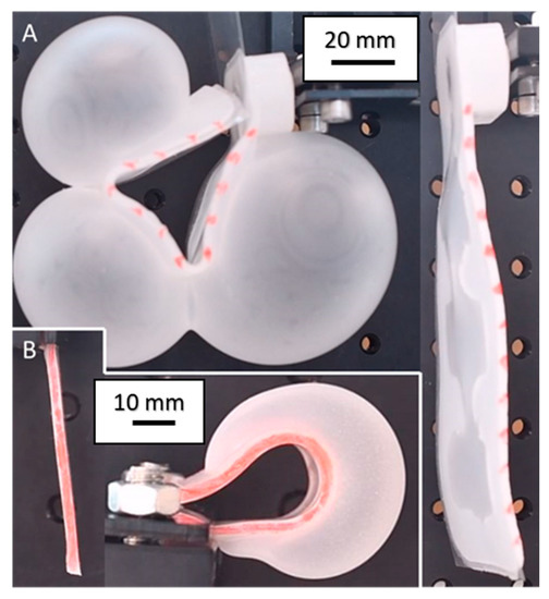
Figure 10.
(A) Large actuator fabricated using Approach 1 in an inflated and deflated state. (B) Actuator fabricated using Approach 2 in an inflated and deflated state.
The actuators fabricated here featured simple designs to demonstrate the robust nature and designed selectivity of the bonding. However, this approach could fabricate actuators of far higher complexity. For example, there is no theoretical limit on the number, shape or thickness of the layers that can be processed, which means that actuators can be efficiently fabricated with dimensional flexibly. This can enable actuators with many separate pneumatic chamber networks, or networks within networks that would be difficult to produce using other methods. Beyond the additional freedom of design granted by this approach, it could also be used synergistically with other manufacturing processes. For example, combination is possible with a process that can deposit functional materials to make state-of-the-art pneumatic soft actuators capable of sensing their position and interactions. While the two-hour wait time for bonding to be completed was the longest part of this process, this has been decreased to 20 min by applying heat and pressure to the bonded area [23].
4. Conclusions
This body of work demonstrated a fabrication method for pneumatic soft actuators that has several advantages over those being currently used. The approach maintains the benefits of being digitally driven like 3D printing methods, but also offers far quicker processing with a wider range of materials and the ability to realise much more complex actuators. It also has a unique characteristic of being able to increase the resolution of the process by a factor of 20 with minor changes to the processing parameters. While the treatment’s resolution using this plasma apparatus is not currently suitable for those requiring feature sizes smaller than 1 mm, it could make the fabrication of larger actuators significantly easier than current methods. Additionally, there is a clear path for the improvement of resolution and potential for the combination with other processes to make a fabrication platform with capabilities extending beyond those of current techniques.
Supplementary Materials
The following are available online at https://www.mdpi.com/2076-0825/9/4/136/s1, Video S1: Fabrication of pneumatic soft actuator using approach 1.
Author Contributions
Conceptualization, L.J.T. and R.A.H.; methodology, L.J.T.; software, L.J.T.; validation, L.J.T.; formal analysis, L.J.T.; investigation, L.J.T.; resources, L.J.T.; data curation, L.J.T.; writing—original draft preparation, L.J.T.; writing—review and editing, R.A.H.; visualization, L.J.T.; supervision, R.A.H.; project administration, L.J.T.; funding acquisition, R.A.H. All authors have read and agreed to the published version of the manuscript.
Funding
This research was funded by the Engineering and Physical Sciences Research Council, grant number EP/P027687/1. Accompanying research data are available from the Research Data Leeds Repository.
Acknowledgments
We acknowledge support from the Henry Royce Institute (EPSRC grants: EP/P022464/1, EP/R00661X/1), which provided the versatile X-ray spectroscopy facility (VXSF) Facilities (https://engineering.leeds.ac.uk/vxsf) within the Bragg Centre for Materials Research at Leeds that were used for the XPS analysis included in this article. We also acknowledge the contributions of Mohammadreza N. Esfahani from our research group who provided some of the initial experimental rig creation, and Paul Roach who advised on the selection of some of the initial plasma components.
Conflicts of Interest
The authors declare no conflict of interest. The funders had no role in the design of the study; in the collection, analyses, or interpretation of data; in the writing of the manuscript; or in the decision to publish the results.
References
- Shepherd, R.F.; Ilievski, F.; Choi, W.; Morin, S.A.; Stokes, A.A.; Mazzeo, A.D.; Chen, X.; Wang, M.; Whitesides, G.M. Multigait soft robot. Proc. Natl. Acad. Sci. USA 2011, 108, 20400–20403. [Google Scholar] [CrossRef] [PubMed]
- Miron, G.; Bédard, B.; Plante, J.-S. Sleeved Bending Actuators for Soft Grippers: A Durable Solution for High Force-to-Weight Applications. Actuators 2018, 7, 40. [Google Scholar] [CrossRef]
- Sinatra, N.R.; Teeple, C.B.; Vogt, D.M.; Parker, K.K.; Gruber, D.F.; Wood, R.J. Ultragentle manipulation of delicate structures using a soft robotic gripper. Sci. Robot. 2019, 4, 33. [Google Scholar] [CrossRef] [PubMed]
- Manti, M.; Hassan, T.; Passetti, G.; D’Elia, N.; Laschi, C.; Cianchetti, M. A Bioinspired Soft Robotic Gripper for Adaptable and Effective Grasping. Soft Robot. 2015, 2, 107–116. [Google Scholar] [CrossRef]
- Zhou, J.; Chen, S.; Wang, Z. A soft-robotic gripper with enhanced object adaptation and grasping reliability. IEEE Robot. Autom. Lett. 2017, 2, 2287–2293. [Google Scholar] [CrossRef]
- Bartlett, N.W.; Lyau, V.; Raiford, W.A.; Holland, D.; Gafford, J.B.; Ellis, T.D.; Walsh, C.J. A soft robotic orthosis for wrist rehabilitation. J. Med Devices Trans. ASME 2015, 9. [Google Scholar] [CrossRef]
- Polygerinos, P.; Galloway, K.C.; Savage, E.; Herman, M.; Donnell, K.O.; Walsh, C.J. Soft robotic glove for hand rehabilitation and task specific training. In Proceedings of the IEEE International Conference on Robotics and Automation (ICRA), Seattle, WA, USA, 26–30 May 2015; pp. 2913–2919. [Google Scholar]
- Noritsugu, T.; Takaiwa, M.; Sasaki, D. Power assist wear driven with pneumatic rubber artificial muscles. In Proceedings of the 15th International Conference on Mechatronics and Machine Vision in Practice, Auckland, New Zealand, 2–4 December 2008; pp. 539–544. [Google Scholar]
- Al-Fahaam, H.; Davis, S.; Nefti-Meziani, S. Wrist rehabilitation exoskeleton robot based on pneumatic soft actuators. In Proceedings of the 2016 International Conference for Students on Applied Engineering (ICSAE 2016), Newcastle upon Tyne, UK, 20–21 October 2016; pp. 491–496. [Google Scholar]
- Lendlein, A.; Kelch, S. Shape-memory polymers. Angew. Chem. Int. Ed. 2002, 41, 2034–2057. [Google Scholar] [CrossRef]
- Nassour, J. Marionette-based programming of a soft textile inflatable actuator. Sens. Actuators A Phys. 2019, 291, 93–98. [Google Scholar] [CrossRef]
- Hinchet, R.; Shea, H. High Force Density Textile Electrostatic Clutch. Adv. Mater. Technol. 2020, 5, 1900895. [Google Scholar] [CrossRef]
- Marchese, A.D.; Rus, D. Design, kinematics, and control of a soft spatial fluidic elastomer manipulator. Int. J. Robot. Res. 2016, 35, 840–869. [Google Scholar] [CrossRef]
- Ilievski, F.; Mazzeo, A.D.; Shepherd, R.F.; Chen, X.; Whitesides, G.M. Soft Robotics for Chemists. Angew. Chem. 2011, 123, 1930–1935. [Google Scholar] [CrossRef]
- Hughes, J.; Culha, U.; Giardina, F.; Guenther, F.; Rosendo, A.; Iida, F. Soft manipulators and grippers: A review. Front. Robot. AI 2016, 3, 1. [Google Scholar] [CrossRef]
- Xia, Y.; Whitesides, G.M. Soft Lithography. Annu. Rev. Mater. Sci. 1998, 28, 153–184. [Google Scholar] [CrossRef]
- Zhang, Y.; Zhang, N.; Hingorani, H.; Ding, N.; Wang, D.; Yuan, C.; Zhang, B.; Gu, G.; Ge, Q. Fast-Response, Stiffness-Tunable Soft Actuator by Hybrid Multimaterial 3D Printing. Adv. Funct. Mater. 2019, 29, 1806698. [Google Scholar] [CrossRef]
- Truby, R.L.; Wehner, M.; Grosskopf, A.K.; Vogt, D.M.; Uzel, S.G.M.; Wood, R.J.; Lewis, J.A. Soft Somatosensitive Actuators via Embedded 3D Printing. Adv. Mater. 2018, 30, 1706383. [Google Scholar] [CrossRef]
- Wallin, T.J.; Pikul, J.; Shepherd, R.F. 3D printing of soft robotic systems. Nat. Rev. Mater. 2018, 3, 84–100. [Google Scholar] [CrossRef]
- Eddings, M.A.; Johnson, M.A.; Gale, B.K. Determining the optimal PDMS-PDMS bonding technique for microfluidic devices. J. Micromech. Microeng. 2008, 18, 067001. [Google Scholar] [CrossRef]
- Sunkara, V.; Park, D.-K.; Cho, Y.-K. Versatile method for bonding hard and soft materials. RSC Adv. 2012, 2, 9066. [Google Scholar] [CrossRef]
- Sunkara, V.; Park, D.K.; Hwang, H.; Chantiwas, R.; Soper, S.A.; Cho, Y.K. Simple room temperature bonding of thermoplastics and poly(dimethylsiloxane). Lab Chip 2011, 11, 962–965. [Google Scholar] [CrossRef]
- Taylor, J.M.; Perez-Toralla, K.; Aispuro, R.; Morin, S.A. Covalent Bonding of Thermoplastics to Rubbers for Printable, Reel-to-Reel Processing in Soft Robotics and Microfluidics. Adv. Mater. 2018, 30, 1705333. [Google Scholar] [CrossRef]
- Roth, J.; Albrecht, V.; Nitschke, M.; Bellmann, C.; Simon, F.; Zschoche, S.; Michel, S.; Luhmann, C.; Grundke, K.; Voit, B. Surface Functionalization of Silicone Rubber for Permanent Adhesion Improvement. Langmuir 2008, 24, 12603–12611. [Google Scholar] [CrossRef] [PubMed]
- Özçam, A.E.; Efimenko, K.; Genzer, J. Effect of ultraviolet/ozone treatment on the surface and bulk properties of poly(dimethyl siloxane) and poly(vinylmethyl siloxane) networks. Polymer 2014, 55, 3107–3119. [Google Scholar] [CrossRef]
- Xiao, D.; Cheng, C.; Shen, J.; Lan, Y.; Xie, H.; Shu, X.; Meng, Y.; Li, J.; Chu, P.K. Characteristics of atmospheric-pressure non-thermal N2 and N2/O2 gas mixture plasma jet. J. Appl. Phys. 2014, 115, 033303. [Google Scholar] [CrossRef]
- Thiyagarajan, M.; Sarani, A.; Nicula, C. Optical emission spectroscopic diagnostics of a non-thermal atmospheric pressure helium-oxygen plasma jet for biomedical applications. J. Appl. Phys. 2013, 113, 233302. [Google Scholar] [CrossRef]
- De Geyter, N.; Morent, R.; Jacobs, T.; Axisa, F.; Gengembre, L.; Leys, C.; Vanfleteren, J.; Payen, E. Remote Atmospheric Pressure DC Glow Discharge Treatment for Adhesion Improvement of PDMS. Plasma Process. Polym. 2009, 6, 406–411. [Google Scholar] [CrossRef]
- Wang, S.; Wan, J. Oxygen effects on a He/O2 plasma jet at atmospheric pressure. IEEE Trans. Plasma Sci. 2009, 37, 551–554. [Google Scholar] [CrossRef]
- Motrescu, I.; Nagatsu, M. Nanocapillary Atmospheric Pressure Plasma Jet: A Tool for Ultrafine Maskless Surface Modification at Atmospheric Pressure. ACS Appl. Mater. Interfaces 2016, 8, 12528–12533. [Google Scholar] [CrossRef]
Publisher’s Note: MDPI stays neutral with regard to jurisdictional claims in published maps and institutional affiliations. |
© 2020 by the authors. Licensee MDPI, Basel, Switzerland. This article is an open access article distributed under the terms and conditions of the Creative Commons Attribution (CC BY) license (http://creativecommons.org/licenses/by/4.0/).