Article

A Comparison Study of a Novel Self-Contained Electro-Hydraulic Cylinder versus a Conventional Valve-Controlled Actuator—Part 2: Energy Efficiency

Department of Engineering Sciences, University of Agder, 4879 Grimstad, Norway
*
Author to whom correspondence should be addressed.
Actuators 2019, 8(4), 78; https://doi.org/10.3390/act8040078
Submission received: 18 November 2019 / Revised: 27 November 2019 / Accepted: 3 December 2019 / Published: 5 December 2019
(This article belongs to the Special Issue Electro-Hydraulic Actuators)

Abstract

:
This research paper presents the second part of a comparative analysis of a novel self-contained electro-hydraulic cylinder with passive load-holding capability against a state of the art, valve-controlled hydraulic system that is typically used in load-carrying applications. After addressing the control design and motion performance in the first part of the study, the comparison is now focused on the systems’ energy efficiency. It is experimentally shown that the self-contained solution enables 62% energy savings in a representative working cycle due to its throttleless and power-on-demand nature. In the self-contained drive, up to 77% of the energy taken from the power supply can be used effectively if the recovered energy is reused, an option that is not possible in the state of the art hydraulic architecture. In fact, more than 20% of the consumed energy may be recovered in the self-contained system during the proposed working cycle. In summary, the novel self-contained option is experimentally proven to be a valid alternative to conventional hydraulics for applications where passive load-holding is required both in terms of dynamic response and energy consumption. Introducing such self-sufficient and completely sealed devices also reduces the risk of oil spill pollution, helping fluid power to become a cleaner technology.

1. Introduction

Due to the increasing focus on the environmental impact, such as CO2 emissions and oil spill pollution, inefficient state of the art hydraulic actuation tends to be replaced by electric drives in many industrial environments. This is the case, for instance, in offshore oil drilling [1]. However, hydraulic systems are still needed in load-carrying applications (e.g., knuckle-boom cranes or oil drilling equipment) because their force density is higher than that of their linear electro-mechanical counterparts and they do not present key issues related to reliability (e.g., strong impact forces) [2].
Consequently, compact and self-contained electro-hydraulic cylinders (SCCs) have received considerable attention in the last decade [3,4,5,6,7,8,9,10], showing the potential to replace both conventional hydraulics and linear electro-mechanical systems [11]. SCCs can in fact enhance energy efficiency, modular design, plug-and-play installation, and reduced maintenance [12]. Current commercial solutions of the SCC technology are limited and typically tailor-made, whereas the research emphasis is primarily on different electro-hydraulic configurations [13,14,15,16], energy-efficiency [17,18,19,20,21], thermal analysis [22,23,24], and low-power servo applications [25]. According to the survey presented in [10], compact and self-contained solutions comprising passive load-holding devices, able to operate in four quadrants, and suitable for power levels above 5 kW are missing, both on the market and in the technical literature. Moreover, the lack of experimental comparisons in terms of energy consumption and efficiency between SCCs and conventional solutions for load-carrying applications is evident. Only a limited number of simulation studies applying the SCC technology to load-carrying applications and investigating the energy-saving potentials compared to existing hydraulic systems were identified [26,27].
Hence, this research paper aims to experimentally evaluate and compare the energy consumption and the energy efficiency of a self-contained electro-hydraulic cylinder versus a conventional approach. A SCC concept able to operate in four quadrants, including passive load holding, and suitable for power levels above 5 kW was proposed in [10] and implemented on a single-boom crane in [12]. A further analysis of this solution is presented in the first part of this research [28], including the control design and the motion performance comparison against the valve-controlled cylinder (VCC) discussed in [29]. Concerning the paper structure, Section 2 presents the two considered actuation systems while Section 3 the theoretical background. In Section 4, the experimental results are introduced and discussed. The comparison study will show that the novel self-contained system is a valid alternative to conventional hydraulics also for applications where passive load-holding is required because huge energy savings are enabled.

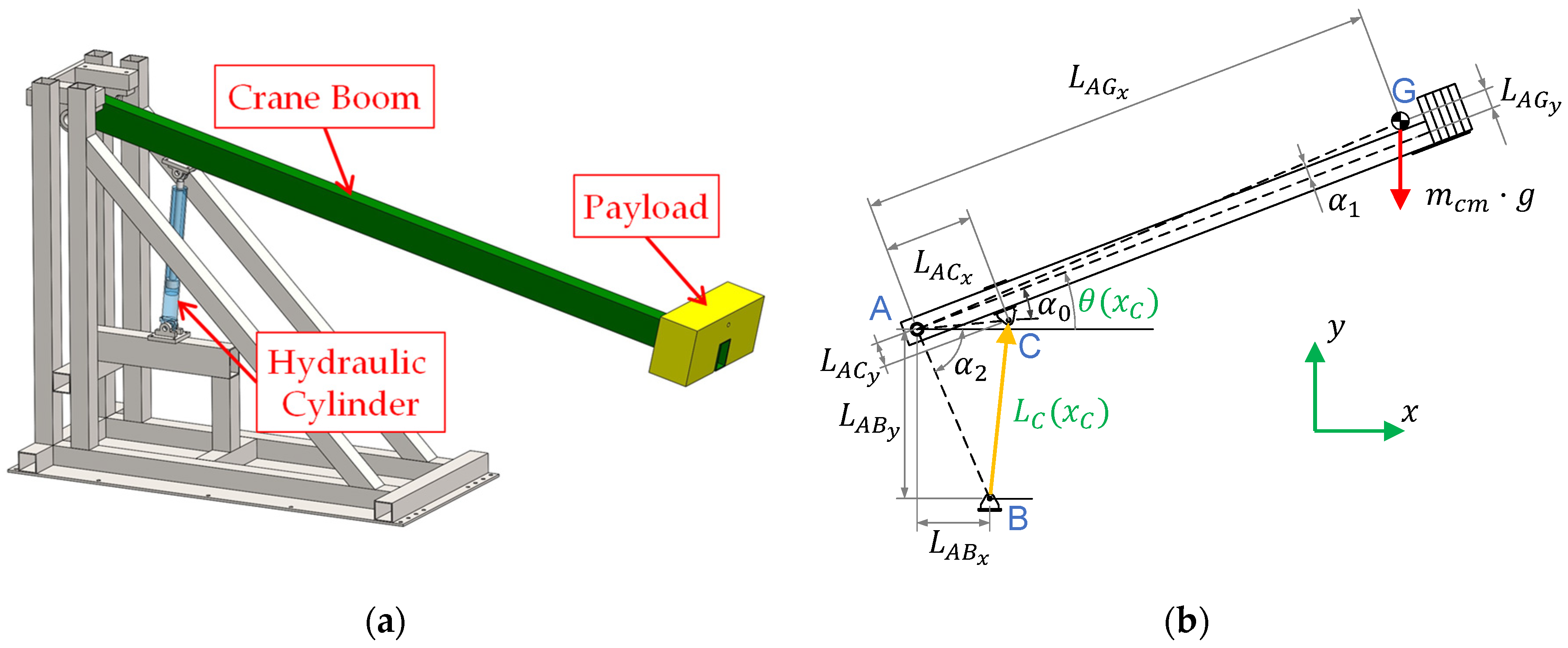
2. The Considered Actuation Systems

Two actuation systems are investigated in this research, namely a new self-contained electro-hydraulic cylinder and state of the art valve-controlled architecture that is typically used on load-carrying applications.

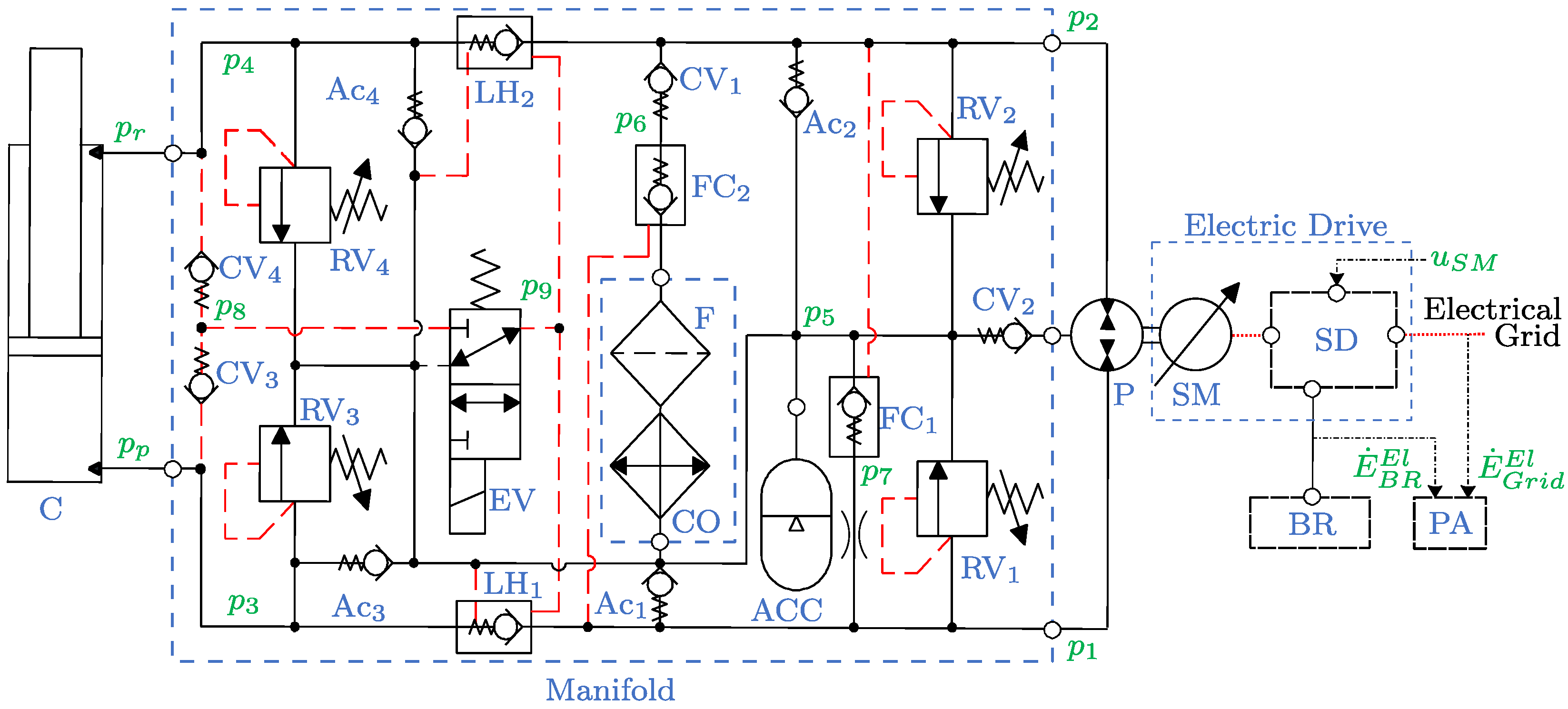
2.1. The Self-Contained Electro-Hydraulic Cylinder

The combination of an electric drive and a fixed-displacement axial piston machine drives the hydraulic cylinder arranged in a closed-circuit configuration, as illustrated in Figure 1.
The auxiliary hydraulic components are implemented in a manifold and the bladder-type accumulator represents the sealed reservoir. The differential flow dictated by the cylinder’s unequal areas is balanced by the two pilot-operated check valves FC1 and FC2, the check valves Ac1 and Ac2, and the check valve CV1. The pilot-operated check valves LH1 and LH2 are used for passive load-holding purposes by isolating the cylinder when the 3/2 electro-valve is not actuated. The electro-valve must be activated to enable the actuator motion, resulting in transferring the highest cylinder pressure, selected through CV3 and CV4, into the opening pilot line of the load-holding valves. Anti-cavitation valves are installed on both actuator sides, whereas pressure-relief valves are present on the pump ports and on the cylinder ports to protect from over-pressurizations. Finally, a cooler and a low-pressure filter complete the hydraulic system.
The electric drive consists of the servo-motor and the servo-drive. The frequency converter is controlling the speed of the permanent magnet synchronous motor with field-oriented control whereas an outer closed-loop position controller is implemented on an embedded programmable logic controller (PLC) to supervise the motion of the hydraulic cylinder, sending the desired rotational speed ( u S M ) to the servo-drive. In addition, an external brake resistor is connected to the servo-drive to dissipate the regenerated power into heat. According to Ristic et al. [30], there exist solutions where this regenerated power is used profitably (e.g., power-sharing via common DC bus between multiple electric drives, return the electrical power to the grid, and energy storage on a battery or in a capacitor). Lastly, a power analyzer measures both the electric power consumed from the electrical grid ( E ˙ G r i d E l ) and the electric power dissipated in the brake resistor ( E ˙ B R E l ). For more details about the self-contained system, Padovani et al. [12] describes its functionality, while the components used to implement this solution are presented in Table 1.
A hydraulic cylinder with piston diameter of 65 mm, rod diameter of 35 mm, stroke length of 500 mm, and an integrated position sensor is common to both actuation systems (i.e., also to the valve-controlled layout recalled in the sequel). The piston’s velocity ( x ˙ C ) is estimated by differentiating and lowpass filtering the measured position ( x C ). Pressure transducers are installed directly on the piston-side ( p p ) and rod-side ( p r ) ports of the cylinder.

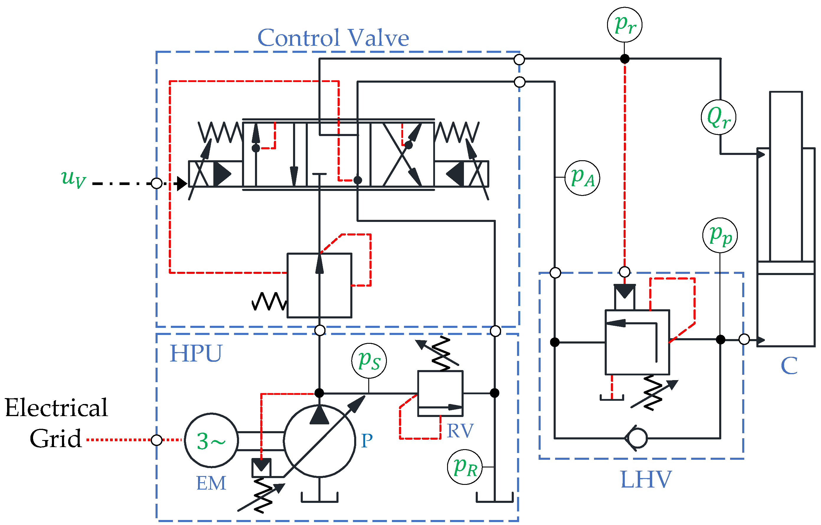
2.2. The Valve-Controlled System

The valve-controlled system taken as a benchmark consists of a centralized hydraulic power unit (HPU) providing a constant supply pressure ( p S ) and a fixed return pressure ( p R ) to the valve-controlled cylinder according to the schematic depicted in Figure 2.
The components of the HPU are an electric motor running at the constant speed of 1500 rpm and a variable-displacement axial piston pump with a maximum displacement of 75 cm 3 / rev . The supply pressure is controlled by the absolute pressure limiter as p S = 180 bar, while a pressure-relief valve is installed for safety. The motion of the hydraulic cylinder is controlled by a state of the art, pressure-compensated flow control valve (i.e., a proportional directional control valve (PDCV)) that receives the control input ( u V ) from the PLC. The load-holding valve is installed to control overrunning loads and for safety purposes during standstill, according to regulations. Finally, the system is instrumented with sensors for measuring the pressures labeled in Figure 2 as well as the rod-side flow rate ( Q R ) and the piston position. For a more detailed description of the functionality of the valve-controlled cylinder, see for instance [29]. Details about the components implemented in the valve-controlled system are presented in Table 2.

3. Theoretical Background

This section describes the analysis performed to process the experimental data collected from the two drive systems. The objective is highlighting the power levels, the energy consumption, and the efficiency of the architectures.

3.1. Power and Energy Distribution

The different power terms characteristic of both systems and highlighted in Figure 3 are evaluated using the equations presented below. For the sake of clarity, the input, the transferred, and the output powers are addressed in separate subsections.

3.1.1. Input Power

The input power of the SCC corresponds to the electric power supplied by the electrical grid:
E ˙ G r i d E l = v a i a + v b i b + v c i c ,
where v i and i i are the voltage and current of the i-th phase, respectively. Furthermore, when the external load is overrunning (i.e., when the cylinder is retracting), the SCC has the potential to regenerate power, while the VCC still consumes energy. For the test setup investigated in this study, the electric power regenerated by the SCC is dissipated in the brake resistor and is estimated according to:
E ˙ B R E l = v B R i B R ,
where v B R is the pulse width modulated voltage, and i B R is the direct current, transferred from the servo-drive to the brake resistor. Hence, the combined input and output powers of the electric drive define the SCC’s total electric power related to the power supply:
E ˙ P S E l = E ˙ G r i d E l + E ˙ B R E l .
The VCC’s input power is the hydraulic term calculated by involving the actuator’s flow demand ( Q P ) and the supply pressure of the HPU:
E ˙ HPU H y d = p S | Q P | ,
where the demand depends on the valve command ( u V ), the measured flow rate ( Q r ), and the areas of the actuator according to the following logic:
Q P = { Q r A p A r , u V < 0 0 , u V = 0 Q r , u V > 0 .

3.1.2. Transferred Power Losses

The mechanical power transferred between the SCC’s servo-motor and the axial piston machine:
E ˙ S M M e c h = i q k t ω S M ,
is described by the torque-producing current component ( i q ), the torque constant ( k t = 2.05 Nm / A ), and the measured rotational speed ( ω S M ) of the prime mover. The hydraulic power shared between the hydraulic machine and the manifold is defined by involving the effective flow supplied to the actuator and the pressure drop across the unit:
E ˙ P H y d = x ˙ C A p ( p 1 p 2 ) .
Then, the hydraulic power distributed between the manifold and the cylinder results as:
E ˙ C H y d = x ˙ C ( A p p p A r p r ) .
The power losses of the SCC take place in the electric drive (i.e., electric and mechanical losses), in the axial piston machine (i.e., mechanical-hydraulic and volumetric losses), in the auxiliary components (i.e., reduced throttling losses in the check valves), and in the hydraulic cylinder (i.e., friction losses and internal leakage).
Concerning the VCC’s, the hydraulic power available downstream the pressure compensator is calculated based on the valve command as:
E ˙ P C H y d = { ( p p + p 0 ) | Q P | , u V < 0 0 , u V = 0 ( p r + p 0 ) | Q P | , u V > 0 ,
including the fixed pressure-drop across the control valve’s metering edge ( p 0 ). Further on, the hydraulic power delivered by the control valve is again function of u V :
E ˙ P D C V H y d = { p p Q P , u V < 0 0 , u V = 0 p r Q P , u V > 0 .
Then, the hydraulic power related to the hydraulic cylinder results as described in Equation (8). The power losses taking place in the VCC are the throttling losses of the pressure compensator, the throttling losses of the control valve’s spools, the throttling losses in the counterbalance valve, and the friction losses and internal leakages of the hydraulic cylinder. Finally, the losses of the HPU are neglected in this experimental study to be conservative, since it is sized for delivering constant pressure to several applications available in the lab.

3.1.3. Output Power

When actuating the considered single-boom crane depicted in Figure 4a, the mechanical output power that is applicable to both systems, is defined as:
E ˙ S B C M e c h = d d t ( E K + E P ) ,
where E K and E P are the kinetic and potential energy, obtained according to Equations (12) and (13).
The diagram shown in Figure 4b identifies the parameters used in the calculation of the total mechanical energy. Relevant numerical values describing the kinematics are listed in Table 3.
The kinetic energy and the potential energy, as a function of the angular speed ( θ ˙ ) and angular position ( θ ) of the boom, are defined according to the following equations:
E K ( θ ˙ ) = 1 2 ( m c m L A G x 2 + m c m L A G y 2 + J c m ) θ ˙ 2 ,
E P ( θ ) = m c m g ( L A G y cos ( θ + α 1 ) + L A G x sin ( θ + α 1 ) ) ,
where the angular position of the boom and the effective length of the hydraulic cylinder ( L C ), including the initial length ( L C , 0 = 772 mm), are given below as a function of the piston position:
θ ( x C ) = cos 1 ( L A C 2 + L A B 2 L C 2 ( x C ) 2 L A C L A B ) α 2 + α 0 ,
L C ( x C ) = x C + L C , 0 .

3.2. Efficiency of the Systems

Starting from the SCC, the overall efficiency ( η O v e r a l l ), the efficiency of the electric drive ( η E D ), and the efficiency of the hydraulic sub-system ( η H S ) are given in Equations (16)–(18). Due to the dual behavior of the system being regenerative while retracting the cylinder (i.e., the load is overrunning when the crane boom is lowered), and consuming when extending the cylinder (i.e., the load is resistant when the crane boom is lifted), two alternatives are introduced in the following definitions:
η O v e r a l l S C C = { E ˙ P S E l E ˙ S B C M e c h , E ˙ P S E l > 0   ( resistant   load ) E ˙ S B C M e c h E ˙ P S E l , E ˙ P S E l 0   ( overrunning   load ) ,
η E D S C C = { E ˙ P S E l E ˙ S M M e c h , E ˙ P S E l > 0   ( resistant   load ) E ˙ S M M e c h E ˙ P S E l , E ˙ P S E l 0   ( overrunning   load ) ,
η H S S C C = { E ˙ S M M e c h E ˙ C H y d , E ˙ S M M e c h > 0   ( resistant   load ) E ˙ C H y d E ˙ S M M e c h , E ˙ S M M e c h 0   ( overrunning   load ) .
Similar terms are also proposed for the VCC, where the efficiency of the control valve ( η V ) and of the remaining hydraulic system, namely the load-holding valve ( η L H V ), are given as follows:
η O v e r a l l V C C = { E ˙ H P U H y d E ˙ S B C M e c h , E ˙ H P U H y d > 0   ( resistant   load ) 0 , E ˙ H P U H y d 0   ( overrunning   load ) ,
η V V C C = { E ˙ H P U H y d E ˙ P D C V H y d , E ˙ H P U H y d > 0   ( resistant   load ) 0 , E ˙ H P U H y d 0   ( overrunning   load ) ,
η L H V V C C = { E ˙ P D C V H y d E ˙ C H y d , E ˙ P D C V H y d > 0   ( resistant   load ) E ˙ C H y d E ˙ P D C V H y d , E ˙ P D C V H y d 0   ( overrunning   load ) .

4. Experimental Results and Discussion

After mentioning the experimental test-beds, the considered working cycle is addressed. Then, the power levels and efficiencies of the different sub-systems are separately evaluated while lifting and lowering the single-boom crane. Finally, the overall energy consumption and efficiency are assessed. The experimental data were collected by using the test setups illustrated in Figure 5.
All data, besides the electric power, is processed through a real-time interface (i.e., 1 ms sample rate) between the PLC and MATLAB-Simulink®. The measured electric power is collected with a 50 ms sample rate and further processed in the MATLAB-Simulink® environment. Mineral oil ISO VG 46 is used as the hydraulic fluid in both actuation systems. All tests were carried out for a working cycle with maximum payload (i.e., with a load mass equal to 304 kg). The motion profile generator, presented in [27], provides reference signals for the desired piston position and velocity, as illustrated in Figure 6. The cylinder’s piston extends and retracts between the start position x C , 0 = 50 mm and the desired position x C , r e f = 450 mm, at a desired maximum velocity v C , m a x = 120   mm / s .
The SCC is operated in closed-loop, including position feedback control, velocity feedforward, pressure feedback, and passive load-holding, according to the control strategy and the control algorithm presented in the first part of this comparison study [28]. In passive load-holding mode, the load-holding valves are closed by deactivating the electro-valve and switching off the signal enabling power to the prime mover when motion is not desired.

4.1. Power Levels

The power levels of the different terms mentioned in Section 3.1 are shown in Figure 7.
When the values in Figure 7 are positive, then the power is transferred to the actuator. Vice versa (i.e., when the trends are negative), there is potential to recover energy. During the crane’s lowering phase, the SCC outputs electrical power, while the VCC dissipates hydraulic energy in the valves. It is worth mentioning that, during steady-state operations, the VCC requires a maximum power of about 7.6 kW while the SCC demands only 4.8 kW (37% less).

4.2. Systems Efficiency

The overall efficiency of both systems is plotted in Figure 8 together with the terms related to the different sub-systems.
The results in Figure 8a show that the SCC’s efficiency, when the cylinder is lifting the crane at steady-state (i.e., at 4 s) is about 60 % for the overall system, 93 % for the electric drive, and 65 % for the hydraulics. The overall efficiency when lowering the crane boom, assuming full recovery of the regenerated power, varies at 51–65 % . It can be observed in Figure 8a that there is a 1.2 s delay between when the SCC starts to lower the crane boom, and the electric drive starts to regenerate power. For the benchmark system (Figure 8b), the overall efficiency is 36 % when the cylinder is lifting the crane boom at steady-state (i.e., at 4 s). Furthermore, almost 50 % of the VCC’s input power is dissipated in the control valve (the most in the pressure-compensator). The efficiency of the counterbalance valve, during lifting (i.e., the flow is bypassed through the LHV’s check valve), is 74 % at the lowest, and at the maximum 51 % through the lowering phase (i.e., the LHV’s poppet introduces a desired pressure-drop).

4.3. Energy Consumption

As described in the first part of this study [28], the SCC can be operated with two different load-holding strategies, namely passive load-holding (PLH) and active load-holding (ALH). The electric power and energy consumption when utilizing these two strategies are compared in Figure 9.
When the SCC maintains the desired piston position between 6.5 and 16 s (Figure 9a), the measured electric input power varies at 5–7 W with passive load-holding, and at 187–312 W with active load-holding. Active load-holding results in an energy consumption of 5.32 Wh for the entire working cycle considered here (Figure 9b), compared to 4.34 Wh with passive load-holding (i.e., 18.4% less). However, performing active load-holding for a reduced amount of time is still acceptable since the power consumption remains relatively low.
Moving to the valve-controlled layout, load-sensing pumps are used instead of constant-pressure supplies to increase the overall efficiency in many applications. Two scenarios are therefore addressed; the first one (Figure 10a) focuses on measurements from the test setup. The scenario #2 (Figure 10b) considers an HPU equipped with a load-sensing pump and driven by an induction motor running at 1500 rpm (the losses of the HPU are simulated based on the model presented in [27]). Full energy recovery is then assumed for the SCC in this second situation (i.e., the energy dissipated in the brake resistor when the SCC is lowering the crane boom is now reused).
The results in Figure 10a show that the SCC does not consume any energy when lowering the load, resulting in 62.1% less consumption compared to the 11.44 Wh of the VCC. This improvement is expected since the VCC needs to build up pressure to enable flow through the counterbalance valve that introduces functional losses, while the SCC uses the highest actuator pressure to fully open the two load-holding valves. For scenario #2 (Figure 10b), the VCC consumes energy also when the cylinder is not moving because the electric-motor is continuously running; due to the load-sensing unit, then 19.6% less energy is taken compared to the VCC in scenario #1. When comparing the two systems in scenario #2, the SCC still consumes less energy than the VCC (62.4% less); this behavior favorable to the SCC is also the case when there is no useful usage of the recovered energy.

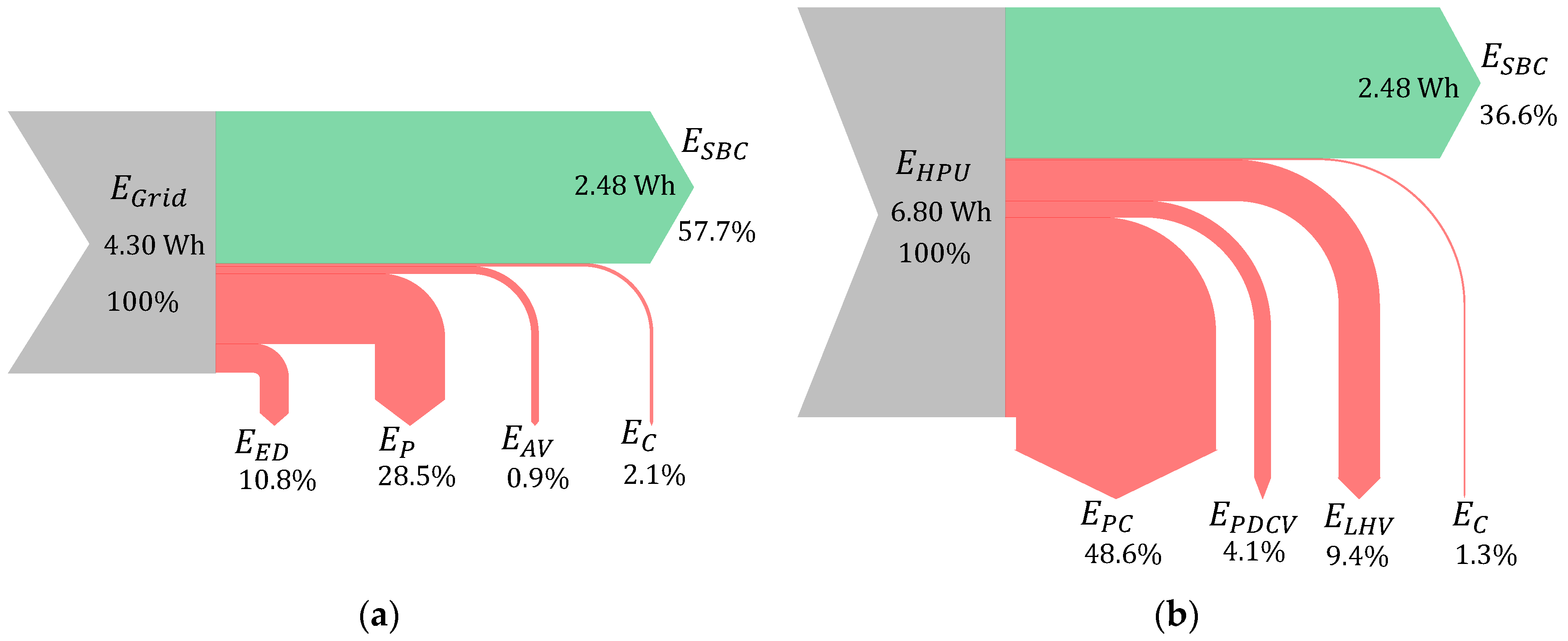
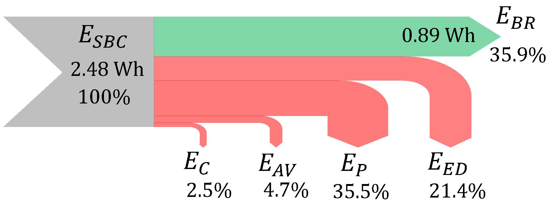
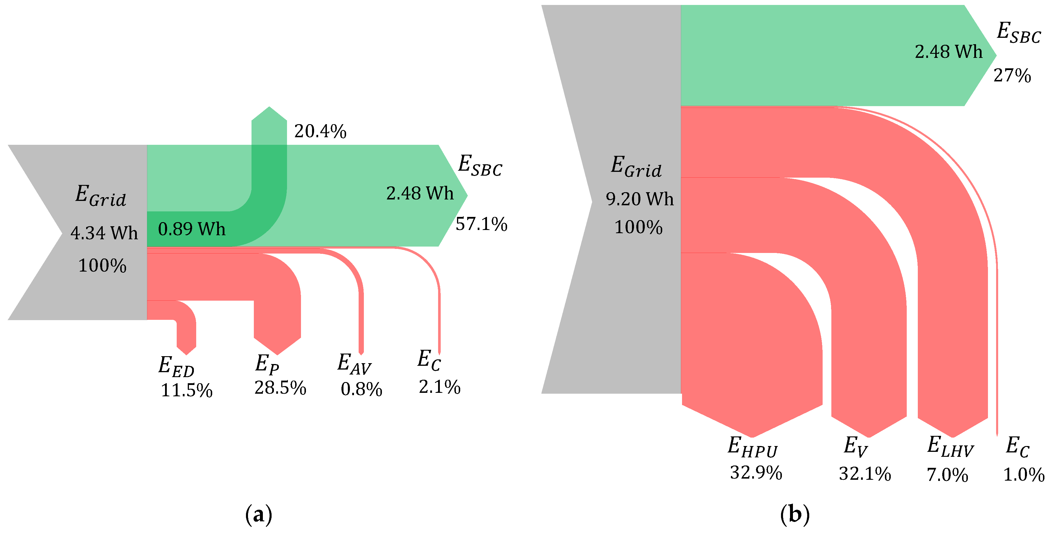
4.4. Energy Distribution

The energy distribution between the main components of the two systems, initially monitored when the cylinder is lifting the crane boom, is illustrated in Figure 11.
The complete energy conversion from the source (i.e., the electric grid for the SCC and the hydraulic power supply for the VCC) to the end user (i.e., the payload of the crane) is handled. The total amount of energy being lost in the SCC is 42.3%, while it increases up to 63.4% in the VCC (this is a conservative estimation because the losses of the HPU are neglected). It should be noted that all losses in the SCC are parasitic, with the pump being the predominant source followed by the electric motor. This aspect does not hold true for the VCC since the compensator introduces a relevant dissipation that is functional (this term could be reduced for higher loads, or when using a load-sensing power supply). Moreover, only the SCC has the potential to recover energy; Figure 12 illustrates the energy distribution in the SCC when the crane boom is lowered.
A significant portion (35.9%) of the energy delivered by the load that is lowered can be outputted by the electric drive; it is worth noticing that this quantity is completely lost in the valve-controlled architecture. In particular, the total energy being dissipated in the SCC during piston retraction (64.1% of the input) is mainly due to the losses in the axial piston machine and in the electric drive.
Finally, the energy distribution during a complete working cycle is depicted in Figure 13 for both the SCC and the VCC, where the energy taken from the grid is now considered also for the VCC (i.e., scenario #2 with the power supply equipped with a load-sensing pump).
The results show that 57.1% of the input energy is transferred to the load for the SCC and 27% for the VCC. Figure 13a reveals that the SCC may recover 20.4% of the electrical energy taken from the grid during a complete working cycle. Assuming a realistic 94% conversion efficiency to return the recovered energy to the grid, then 76.5% of the total energy taken from the source can be used effectively. Further on, when considering a VCC supplied by a load-sensing pump (Figure 13b), the efficiency increases due to the major reduction of the functional losses in the control valve ( E V ). However, including also the inefficiencies of the HPU (i.e., the losses of the electric motor and of the pump), the overall efficiency is only increased by 5.3% compared to the VCC supplied with constant pressure supply (scenario #1) that is characterized by an overall energy efficiency of 21.7%.

5. Conclusions

This research paper experimentally compares a novel self-contained electro-hydraulic cylinder and a hydraulic, valve-controlled, linear actuator representative of the state of the art in many fields of industry. A single-boom crane requiring passive load-holding is taken as the reference application, while the emphasis of the study is placed on the energy efficiency of the drives. The results show that the electro-hydraulic layout reduces the energy consumption significantly (up to 62% less) due to its throttleless nature and power-on-demand functioning. More specifically, the following aspects emerge from the study:
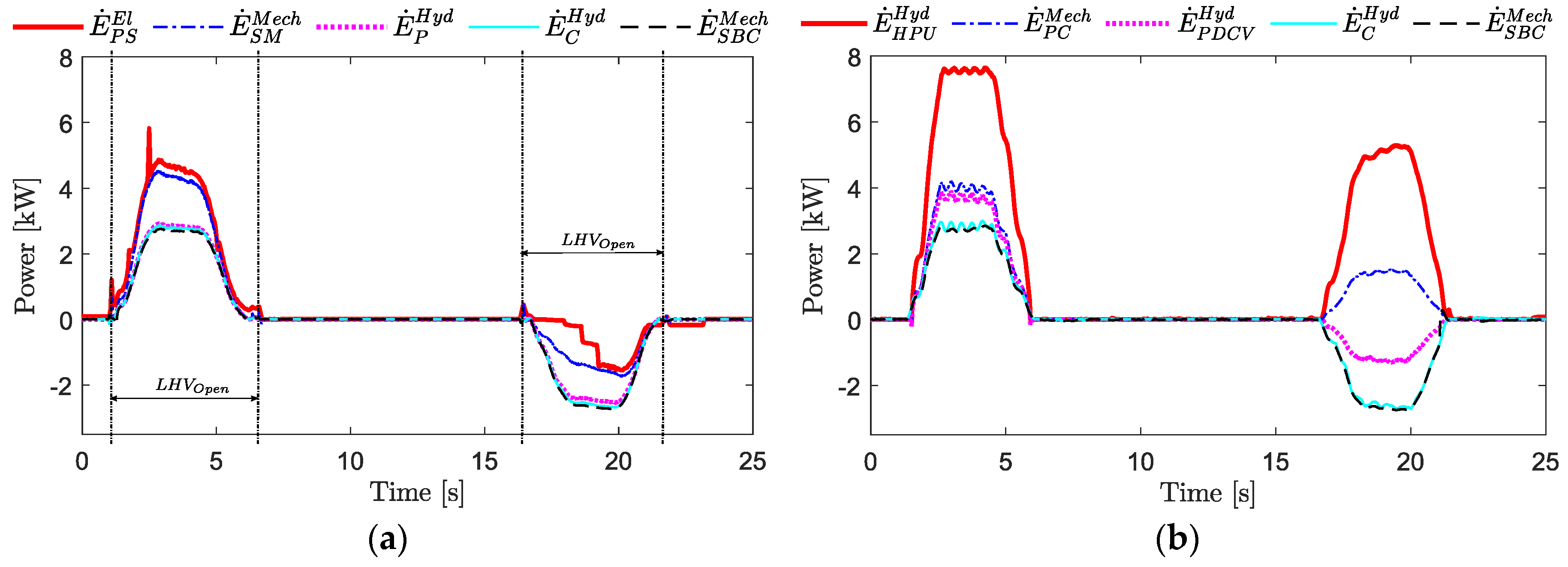
  • The power demand to the prime mover during steady-state operations reduces to 4.8 kW against the 7.6 kW in the valve-controlled system (37% less) throughout the investigated working cycle;
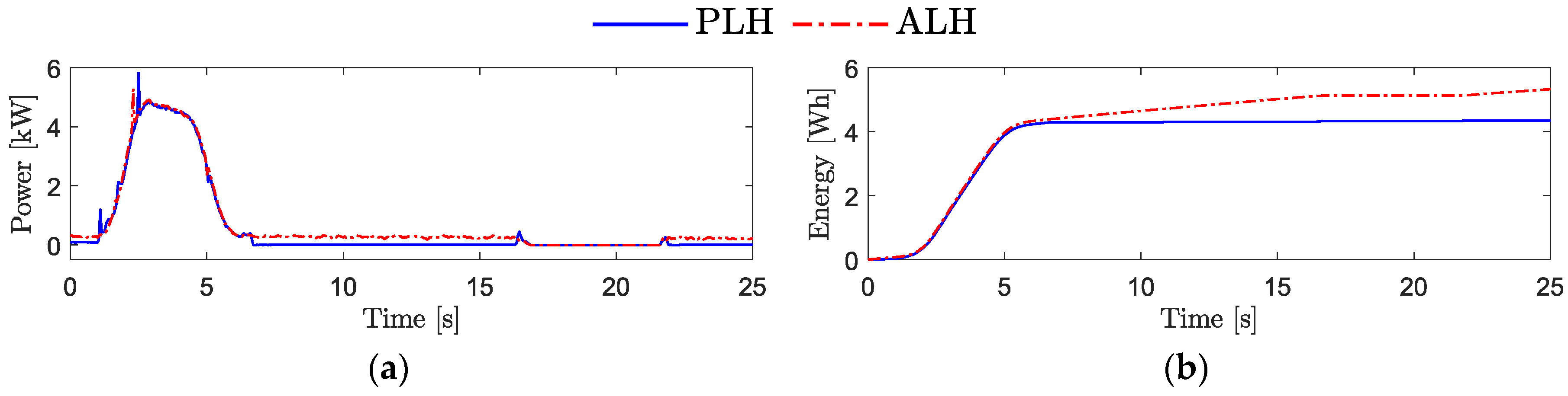
  • Utilizing passive load-holding results in an energy saving of 18.4% compared to actively controlling the SCC’s desired position using the prime mover during load holding phases;
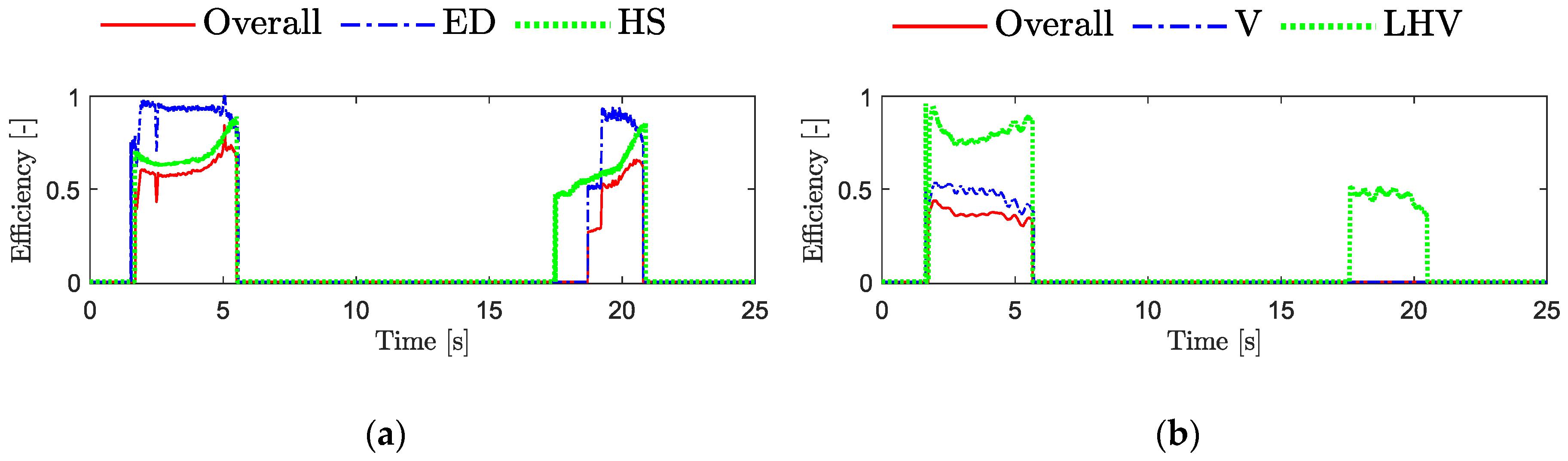
  • The system’s overall efficiency of the self-contained drive, being approximately 57% during actuation, turns out to be highly satisfactory compared to the 22% efficiency of the valve-controlled system with a constant-pressure supply;
  • A significant amount of energy (i.e., 20% of the consumed energy) is recovered by the self-contained solution during the proposed working cycle. Hence, when assuming a realistic 94% conversion efficiency to return the recovered energy to the grid, then 77% of the total energy taken from the source can be used effectively. In contrast, this efficient operation is not possible in the valve-controlled system where, rather than being recovered, the available energy is dissipated when the load acting on the actuator is overrunning;
  • An alternative scenario based on the load-sensing concept is also considered for the valve-controlled system; its energy consumption reduces from 11.44 Wh to 9.20 Wh but remains inefficient with respect to the electro-hydraulic actuator (i.e., total consumption 4.34 Wh).
Recalling the positive outcomes about motion control obtained in the first part of the research and disseminated in a different article, it is therefore concluded that the novel energy-efficient, self-contained drive represents a valid alternative to conventional hydraulic systems for load-carrying applications. Introducing a self-sufficient and completely sealed device also reduces the risk of oil spill pollution, helping fluid power to become a cleaner technology. Concerning future developments about the self-contained system, effort will be placed on both optimizing the sizing procedure to maximize energy efficiency as well as on designing and testing advanced solutions that reuse the recovered energy.

Author Contributions

Conceptualization, D.H. and D.P.; methodology, D.H.; software, D.H.; validation, D.H.; formal analysis, D.H.; investigation, D.H.; data curation, D.H.; writing—original draft preparation, D.H.; writing—review and editing, D.H., D.P., and M.C.; visualization, D.H.; supervision, D.P. and M.C.

Funding

This research was funded by the Norwegian Research Council, SFI Offshore Mechatronics, project 237896.

Conflicts of Interest

The authors declare no conflict of interest.

Nomenclature

Abbreviations
ACAlternating current
ACCAccumulator
AcAnti-cavitation valve
ALHActive load-holding
AVAuxiliary valves
BRBrake resistor
CHydraulic cylinder
COOil cooler
CVCheck valve
DCDirect current
EDElectric drive
EMElectric motor
EVElectro-valve
FLow pressure oil filter
FCFlow compensation valve
HPUHydraulic power unit
HSHydraulic system
LHVLoad-holding valve
PAxial piston machine (pump)
PDCVProportional directional control valve
PLCProgrammable logic controller
RVPressure-relief valve
SBCSingle-boom crane
SCCSelf-contained electro-hydraulic cylinder
SDServo-drive
SMServo-motor
VControl valve
VCCValve-controlled cylinder
Symbols
A p Cylinder area on the piston-side
A r Cylinder area on the rod-side
E K Kinetic energy
E P Potential energy
E Energy
E ˙ Power
i a , i b , i c Three-phase current of the electric power supply
i B R Direct current of the brake resistor
i q Torque-producing current component
J c m Inertia at center of mass
k t Torque constant
L A B Length between joint A and B
L A C Length between joint A and C
L A G x Length between joint A and G in x-direction
L A G y Length between joint A and G in y-direction
L C , 0 Length of the hydraulic cylinder when fully retracted
L C Effective total length of the hydraulic cylinder
m c m Mass at center of mass
ω S M Rotational speed of the servo-motor in radians per seconds
Q P Actuator’s flow demand
Q r Rod-side flow rate
p 0 Fixed pressure-drop across the proportional directional control valve
p 1 Pressure at the pump/motor port on the piston-side of the actuator
p 2 Pressure at the pump/motor port on the rod-side of the actuator
p p Actuator’s piston chamber pressure
p r Actuator’s rod chamber pressure
p R Return pressure
p S Supply pressure
u S M Commanded servo-motor speed
u V Commanded opening of the control valve’s spool position
v a , v b , v c Three-phase voltage of the electric power supply
v B R Direct current voltage of the brake resistor
x C Actuator’s piston position
x ˙ C Actuator’s piston velocity
Greek Symbols
α i Arctangent of the xy-length between the i-th joints
η i Efficiency of the i-th system
θ Angular position of the boom

References

  1. Pawlus, W.; Choux, M.; Hansen, M.R. Hydraulic vs. electric: A review of actuation systems in offshore drilling equipment. Model. Identif. Control 2016, 37, 1–17. [Google Scholar] [CrossRef] [Green Version]
  2. Hagen, D.; Pawlus, W.; Ebbesen, M.K.; Andersen, T.O. Feasibility Study of Electromechanical Cylinder Drivetrain for Offshore Mechatronic Systems. Model. Identif. Control 2017, 38, 59–77. [Google Scholar] [CrossRef] [Green Version]
  3. Michel, S.; Weber, J. Electrohydraulic Compact-Drives for Low Power Applications Considering Energy-efficiency and High Inertial Loads. In Proceedings of the 7th FPNI PhD Symposium on Fluid Power, Reggio Emilia, Italy, 27–30 June 2012; pp. 27–30. [Google Scholar]
  4. Minav, T.A.; Sainio, P.; Pietola, M. Direct Driven Hydraulic Drive without Conventional Oil Tank. In Proceedings of the ASME/BATH 2014 Symposium on Fluid Power and Motion Control, Bath, UK, 10–12 September 2014. [Google Scholar]
  5. Altare, G.; Vacca, A.; Richter, C. A Novel Pump Design for an Efficient and Compact Electro-Hydraulic Actuator. In Proceedings of the IEEE Aerospace Conference, Big Sky, MT, USA, 1–8 March 2014. [Google Scholar]
  6. Altare, G.; Vacca, A. A design solution for efficient and compact electro-hydraulic actuators. Procedia Eng. 2015, 106, 8–16. [Google Scholar] [CrossRef] [Green Version]
  7. Rexroth, B. Electrification and Digitalization: The Fitness Program for Hydraulics. 2015. Available online: https://www.boschrexroth.com/en/xc/products/product-groups/industrial-hydraulics/the-fitness-program-for-hydraulics (accessed on 21 September 2019).
  8. Helbig, A.; Boes, C. Electric Hydrostatic Actuation-Modular Building Blocks for Industrial Applications. In Proceedings of the 10th International Fluid Power Conference, Dresden, Germany, 8–10 March 2016; pp. 93–102. [Google Scholar]
  9. Pedersen, H.C.; Schmidt, L.; Andersen, T.O.; Brask, M.H. Investigation of New Servo Drive Concept Utilizing Two Fixed Displacement Units. Int. J. Fluid Power Syst. 2014, 8, 1–9. [Google Scholar] [CrossRef] [Green Version]
  10. Hagen, D.; Padovani, D.; Ebbesen, M.K. Study of a Self-Contained Electro-Hydraulic Cylinder Drive. In Proceedings of the 2018 Global Fluid Power Society Ph.D. Symposium (GFPS), Samara, Russia, 18–20 July 2018. [Google Scholar]
  11. Michel, S.; Weber, J. Energy-Efficient Electrohydraulic Compact Drives for Low Power Applications. In Proceedings of the ASME/BATH 2012 Symposium on Fluid Power and Motion Control, Bath, UK, 12–14 September 2012; pp. 93–107. [Google Scholar]
  12. Padovani, D.; Ketelsen, S.; Hagen, D.; Schmidt, L. A Self-Contained Electro-Hydraulic Cylinder with Passive Load-Holding Capability. Energies 2019, 12, 292. [Google Scholar] [CrossRef] [Green Version]
  13. Jalayeri, E.; Imam, A.; Tomas, Z.; Sepehri, N. A throttle-less single-rod hydraulic cylinder positioning system: Design and experimental evaluation. Adv. Mech. Eng. 2015, 7, 1687814015583249. [Google Scholar] [CrossRef] [Green Version]
  14. Weber, I.J.; Schneider, D.I.; Shabi, M.S.; Sitte, D.I.; Weber, D.I.; Willkomm, D.I.; Beck, D.I.; Fischer, D.I.; Ivantysyn, M.S.; Kolks, D.I.; et al. Novel System Architectures by Individual Drives. In Proceedings of the 10th International Fluid Power Conference, Dresden, Germany, 8–10 March 2016; pp. 29–62. [Google Scholar]
  15. Ketelsen, S.; Padovani, D.; Andersen, T.; Ebbesen, M.; Schmidt, L. Classification and Review of Pump-Controlled Differential Cylinder Drives. Energies 2019, 12, 1293. [Google Scholar] [CrossRef] [Green Version]
  16. Schmidt, L.; Ketelsen, S.; Brask, M.H.; Mortensen, K.A. A class of energy efficient self-contained electro-hydraulic drives with self-locking capability. Energies 2019, 12, 1866. [Google Scholar] [CrossRef] [Green Version]
  17. Minav, T.A.; Laurila, L.I.E.; Pyrhönen, J.J. Analysis of electro-hydraulic lifting system’s energy efficiency with direct electric drive pump control. Autom. Constr. 2013, 30, 144–150. [Google Scholar] [CrossRef]
  18. Minav, T.A.; Sainio, P.; Pietola, M. Efficiency of Direct Driven Hydraulic Setup in Arctic Conditions. In Proceedings of the Fourteenth Scandinavian International Conference on Fluid Power, Tampere, Finland, 20–22 May 2015. [Google Scholar]
  19. Schmidt, L.; Roemer, D.B.; Pedersen, H.C.; Andersen, T.O. Speed-Variable Switched Differential Pump System for Direct Operation of Hydraulic Cylinders. In Proceedings of the ASME/BATH Symposium on Fluid Power and Motion Control, Chicago, IL, USA, 12–14 October 2015. [Google Scholar]
  20. Schneider, M.; Koch, O.; Weber, J. Green Wheel Loader—Improving Fuel Economy through Energy Efficient Drive and Control Concepts. In Proceedings of the 10th International Fluid Power Conference, Dresden, Germany, 8–10 March 2016; pp. 63–78. [Google Scholar]
  21. Schmidt, L.; Ketelsen, S.; Padovani, D.; Mortensen, K.A. Improving the Efficiency and Dynamic Properties of a Flow Control Unit in a Self-Locking Compact Electro-Hydraulic Cylinder Drive. In Proceedings of the ASME/Bath Symposium on Fluid Power and Motion Control, Longboat Key, FL, USA, 7–9 October 2019. [Google Scholar]
  22. Michel, S.; Weber, J. Prediction of the Thermo-Energetic Behaviour of an Electrohydraulic Compact Drive. In Proceedings of the 10th International Fluid Power Conference, Dresden, Germany, 8–10 March 2016; pp. 219–234. [Google Scholar]
  23. Minav, T.; Papini, L.; Pietola, M. A Thermal Analysis of Direct Driven Hydraulics. In Proceedings of the 10th International Fluid Power Conference, Dresden, Germany, 8–10 March 2016; pp. 235–248. [Google Scholar]
  24. Karlén, N.; Minav, T.A.; Pietola, M. Investigation of Thermal Effects in Direct Driven Hydraulic System for Off-Road Machinery. In Proceedings of the 9th FPNI Ph.D. Symposium on Fluid Power, Florianópolis, Brazil, 26–28 October 2016. [Google Scholar]
  25. Schmidt, L.; Groenkjaer, M.; Pedersen, H.C.; Andersen, T.O. Position Control of an Over-Actuated Direct Hydraulic Cylinder Drive. Control Eng. Pract. 2017, 64, 1–14. [Google Scholar] [CrossRef]
  26. Ketelsen, S.; Schmidt, L.; Donkov, V.H.; Andersen, T.O. Energy saving potential in knuckle boom cranes using a novel pump controlled cylinder drive. Model. Identif. Control 2018, 39, 73–89. [Google Scholar] [CrossRef] [Green Version]
  27. Hagen, D.; Padovani, D.; Choux, M. Enabling Energy Savings in Offshore Mechatronic Systems by using Self-Contained Cylinders. Model. Identif. Control 2019, 40, 89–108. [Google Scholar] [CrossRef]
  28. Hagen, D.; Padovani, D.; Choux, M. A Comparison Study of a Novel Self-Contained Electro-Hydraulic Cylinder versus a Conventional Valve-Controlled Actuator—Part 1: Motion Control. Actuators 2019, in press. [Google Scholar]
  29. Hagen, D.; Padovani, D.; Choux, M. Design and Implementation of Pressure Feedback for Load-Carrying Applications with Position Control. In Proceedings of the Sixteenth Scandinavian International Conference on Fluid Power, Tampere, Finland, 22–24 May 2019. [Google Scholar]
  30. Ristic, M.; Wahler, M. Electrification of Hydraulics Opens New Ways for Intelligent Energy-Optimized Systems. In Proceedings of the 11th International Fluid Power Conference, Aachen, Germany, 19–21 March 2018. [Google Scholar]
Figure 1. Schematic of the self-contained system addressed in this research.
Actuators 08 00078 g001
Figure 2. Schematics of the valve-controlled system under investigation.
Actuators 08 00078 g002
Figure 3. The different power terms: (a) Self-contained system; (b) valve-controlled system.
Actuators 08 00078 g003
Figure 4. The considered application: (a) The hydraulic actuator connected to the crane-boom; (b) simplified schematic diagram of the crane’s kinematics.
Actuators 08 00078 g004
Figure 5. The experimental setups: (a) The self-contained electro-hydraulic system; (b) a portion of the valve-controlled system.
Actuators 08 00078 g005
Figure 6. Generated motion profile: (a) Desired piston position; (b) desired piston velocity.
Actuators 08 00078 g006
Figure 7. Power measurements: (a) Self-contained system; (b) valve-controlled system.
Actuators 08 00078 g007
Figure 8. Efficiency of the systems: (a) Self-contained system; (b) valve-controlled system.
Actuators 08 00078 g008
Figure 9. Comparison between passive and active load-holding for the self-contained cylinder: (a) Input power; (b) energy consumption.
Actuators 08 00078 g009
Figure 10. Energy consumption comparison: (a) The scenario #1; (b) the scenario #2.
Actuators 08 00078 g010
Figure 11. The energy distribution when lifting the crane boom: (a) Self-contained system; (b) valve-controlled system.
Actuators 08 00078 g011
Figure 12. The energy distribution of the self-contained system when lowering the crane boom.
Actuators 08 00078 g012
Figure 13. The energy distribution during a complete working cycle: (a) Novel self-contained system; (b) valve-controlled system when simulating a load-sensing pump and hydraulic power unit losses.
Actuators 08 00078 g013
Table 1. Components used to implement the self-contained system.
SymbolComponentManufacturerModel
CHydraulic cylinderPMC Cylinders 125CAL
SMServo-motorBosch Rexroth 2MSK071E-0300
PAxial piston machineBosch RexrothA10FZG
SDServo-driveBosch RexrothHCS02.1E-W0054
ACCHydro-pneumatic accumulatorBosch RexrothHAB10
COOil coolerBosch RexrothKOL3N
FHydraulic return line filterBosch Rexroth50LEN0100
LHV1,2Pilot-operated check valvesSun Hydraulics 3CVEVXFN
FC1,2Pilot-operated check valvesSun HydraulicsCKEBXCN
RV1–4Pressure-relief valvesSun HydraulicsRDDA
CV1,3,4Check valvesHawe Hydraulik 4RB2
CV2, Ac1,2Check valvesHawe HydraulikRK4
Ac3,4Check valvesHawe HydraulikRK2
EV3/2 Directional valveArgo Hytos 5SD1E-A3
p 1–9Pressure transducersBosch RexrothHM20
p p,rPressure transducersParker 6SCP-400
x C Cylinder position sensorRegal 7PS6300
PLCEmbedded controllerBosch RexrothXM22
BRBrake resistorBosch RexrothHLR01.1N-03K8
PAPower analyzerHioki 8PW6001
1 Sävsjö, Sweden; 2 Lohr, Germany; 3 Sarasota, USA; 4 München, Germany; 5 Zug, Switzerland; 6 Cleveland, USA; 7 Uppsala, Sweden; 8 Nagano, Japan.
Table 2. Components used to implement the valve-controlled system.
SymbolComponentManufacturerModel
EMElectric motorASEA 1M225S60-4
PAxial piston variable pumpBrueninghaus Hydraulik 2A4V-S0-71
RVPressure-relief valveBosch RexrothDBDH6
VFlow control valveSauer Danfoss 3PVG32-9781
LHVCounterbalance valveSun HydraulicsCWCA
p S,R,APressure transducersParkerSCP-400
QrFlow rate meterParkerSCQ-150
1 Västerås, Sweden; 2 Horb, Germany; 3 Nordborg, Denmark.
Table 3. Kinematic parameters of the single-boom crane with full payload.
ParameterValueParameterValue
m c m 415.08 (kg) L A B 1136 (mm)
J c m 159.63 (kg·m2) α 0 0.232 (rad)
L A G x 3139 (mm) α 1 0.020 (rad)
L A G y 64 (mm) α 2 1.192 (rad)
L A C 565 (mm) g 9.81 (m/s2)

