Article

Thermal Balance and Active Damping of a Piezoelectric Deformable Mirror for Adaptive Optics

1
Department of Control Engineering and System Analysis, Université Libre de Bruxelles (ULB), CP. 165-55, 50 Av. F.D. Roosevelt, B-1050 Brussels, Belgium
2
European Space Agency—ESA/ESTEC, Opto-Electronics Section, Keplerlaan 1, 2201 AZ Noordwijk ZH, The Netherlands
*
Author to whom correspondence should be addressed.
Actuators 2019, 8(4), 75; https://doi.org/10.3390/act8040075
Submission received: 14 October 2019 / Revised: 24 October 2019 / Accepted: 26 October 2019 / Published: 1 November 2019

Abstract

:
Piezoelectric unimorph deformable mirrors offer a cheap solution to adaptive optics, with mass production capability. However, standard solutions have significant drawbacks: (i) the static shape is sensitive to the temperature, and (ii) the low structural damping limits the control bandwidth, because of the interaction between the shape control and the vibration modes of the mirror. This paper discusses how these two problems may be alleviated by using a mirror covered with an array of actuators working in d31 mode on the back side and a ring of transducers (actuators and sensors) on the front side, outside the pupil of the mirror.

1. Introduction

The variation of the speed of light due to the random variation of the refraction index in the Earth’s atmosphere distorts the wavefront of incoming plane waves of distant stars; this phenomenon, called atmospheric turbulence, limits the resolution of Earth-based telescopes and has been used to promote space astronomy. This limit resolution (called seeing) is given by λ / r 0 , where λ is the wavelength and r 0 is the Fried length, the maximum size of a diffraction-limited telescope for a given site ( r 0 depends on the wavelength, r 0 = 10–20 cm for λ = 0.55 μm and r 0 = 53–106 cm for λ = 2.2 μm) [1]. Adaptive optics (AO) allows improving the resolution of the telescopes by correcting the wavefront error by means of a deformable mirror (DM); if the latter has enough independent actuators with adequate stroke to accommodate complex shapes and enough bandwidth to handle the rapid variations of the wavefront error, the resolution may be extended to the diffraction limit λ / D , where D is the telescope aperture (i.e., the diameter of the primary mirror). Comparing D and r 0 gives an idea of the huge benefit of AO for astronomy. There are AO mirrors of all sizes, but a minimum size is generally required by the field of view of the telescope; the typical DM diameter for a few hundred actuators is 150–200 mm [2]; the European Southern Observatory’s (ESO) future Extremely Large Telescope (ELT) will have an AO mirror of 2.5 m with 5800 actuators [3]. As the size of the mirror grows, the natural frequencies of the vibration modes drop and the vibration modes tend to be excited by the control system, limiting the control bandwidth f c to a fraction of the natural frequency f 1 of the lowest vibration mode. Typical values of f 1 / f c depend on the structural damping of the DM.
In a recent paper [4], the passive and active damping augmentation of piezoelectric DMs was investigated. The passive damping was achieved by providing the front side of the DM, outside the pupil, with a ring of piezoelectric ceramic (PZT) [5] used simultaneously to reduce the thermal sensitivity of the mirror and to provide passive shunt damping of the critical mode at f 1 by connecting it to an appropriate, properly tuned R–L circuit [6]. Alternatively, a strategy for active damping was also proposed, where the wavefront sensor array, a Shack–Hartmann (SH) in this case, and the shape control actuators (the PZT array on the back of the DM) are used to construct modal filters and introduce active damping in the critical mode(s). There were two difficulties: (i) the wavefront sensor has a limited bandwidth because of the time needed for data acquisition (typically 1000 Hz or at most 2000 Hz for an SH), which can lead to time aliasing of some vibration modes, and (ii) the wavefront sensor covers only part of the mirror (the pupil), which leads to a possible confusion in the mode shapes. In this study, it is proposed to partition the ring actuator on the front side of the mirror in such a way that the confusion between mode shapes mentioned above is eliminated, leading to a better modal reconstruction. Furthermore, this configuration allows a full (active) thermal control of the mirror.

2. Baseline Configuration

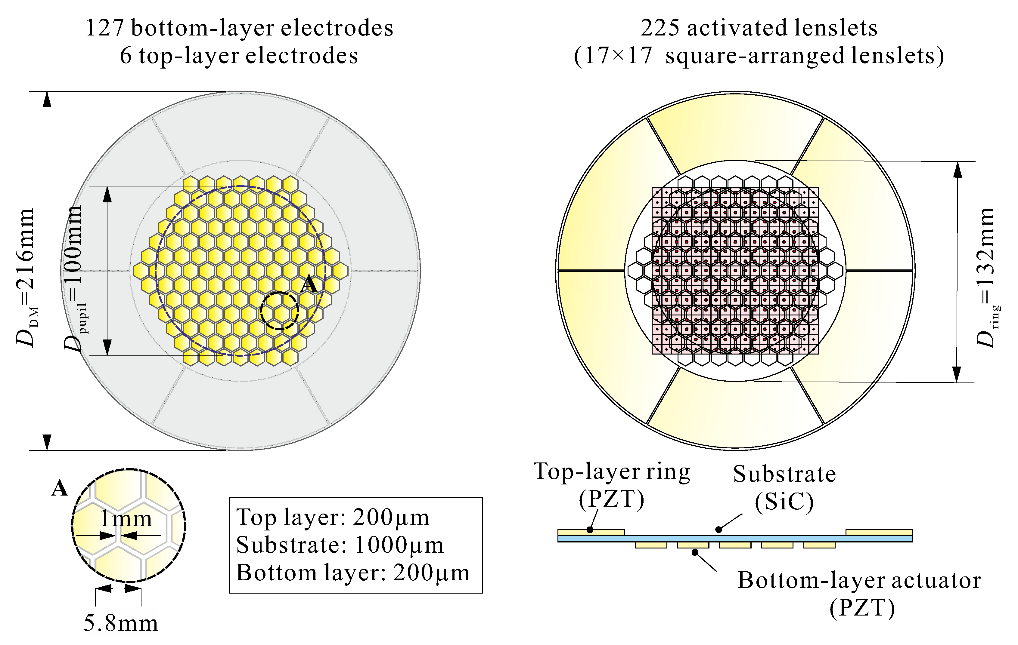
The configuration considered in [4] is represented in Figure 1; it consists of a 1 mm thick SiC substrate of 216 mm diameter, simply supported on its edges, covered on its back by an array of 127 PZT actuators of 200 μm, with honeycomb electrodes. The pupil has a diameter of 100 mm, and the SH sensor consists of a square array of 17 × 17 lenslets (225 activated). The front side of the mirror is provided with a ring of PZT material outside the pupil. The telescope aperture is assumed to have an aperture D = 5 m, the Fried length r 0 = 79 cm (defined at λ = 2.2 μm for a seeing of 0.57 arcsec), and the wind speed V = 10 m/s.
The static relationship between the 127 input voltages v and the SH output signals s is
s = J v .
The Jacobian J is a rectangular matrix that describes the quasi-static behavior of the mirror, at frequencies such that f f 1 ; the pseudo-inverse J may be computed by singular value decomposition (SVD). If J = U Σ V T ,
v = J s with J = V Σ U T .
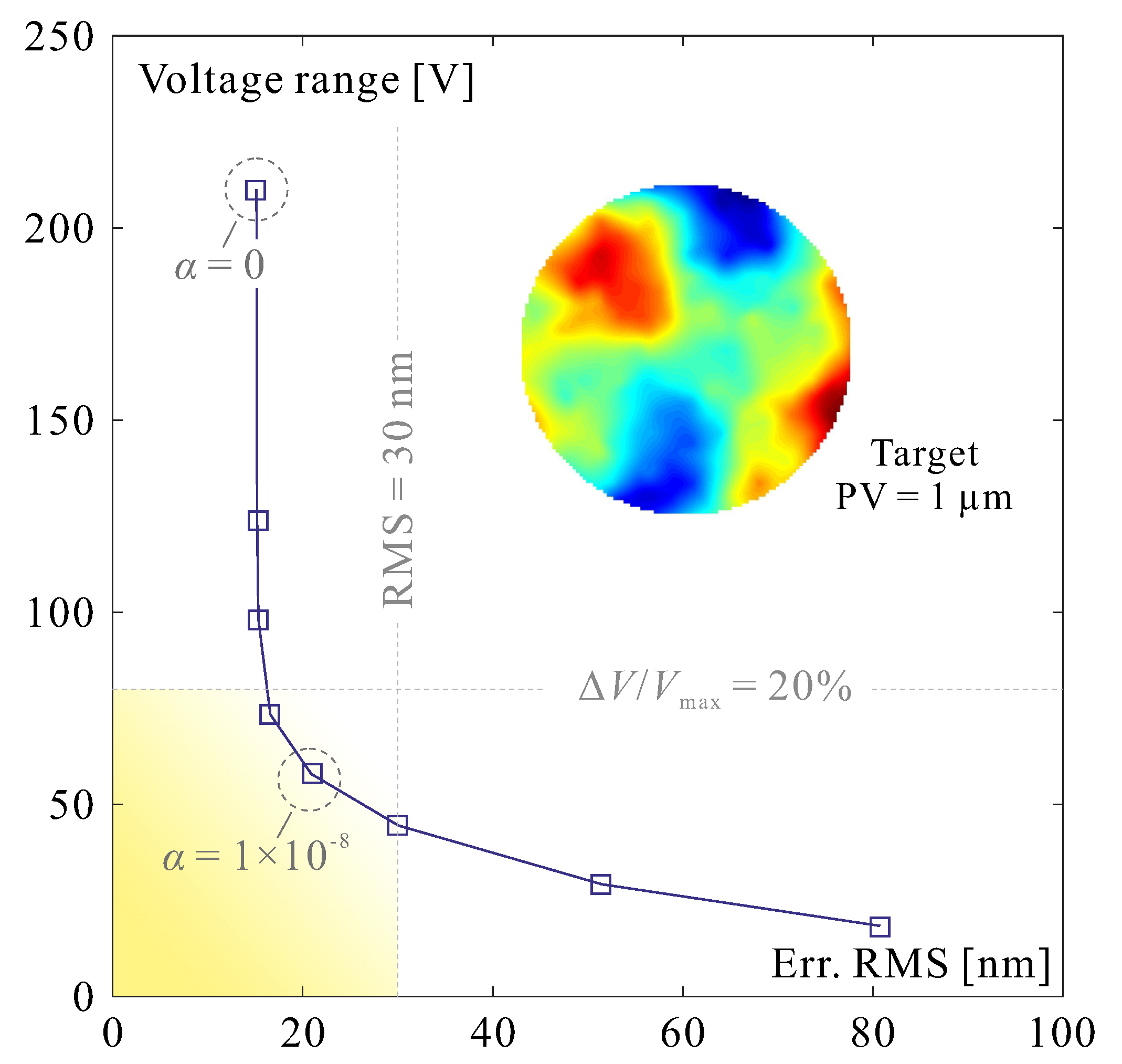
In order to alleviate the ill-conditioning associated with the lowest singular values, which is responsible for unnecessarily large control voltages without any benefit to the fitting error, a Tikhonov regularization may be used; the pseudo-inverse reads
J = ( J T J + α 2 I ) 1 J T ,
where α 2 is a tuning parameter ( α has the same dimension as the elements of J); this method is often called damped least squares [7]. Figure 2 shows the result of a simulation performed with randomly generated turbulent screens. It shows the evolution of the voltage range Δ V and the root mean square (RMS) residual surface figure error as a function of the damping coefficient α for a typical turbulent screen; one sees that a value of α = 10 8 reduces considerably the voltage range without significantly increasing the residual wavefront error. Note that the deformable mirror will introduce a modification of the wavefront twice that of the deformed mirror within the pupil.
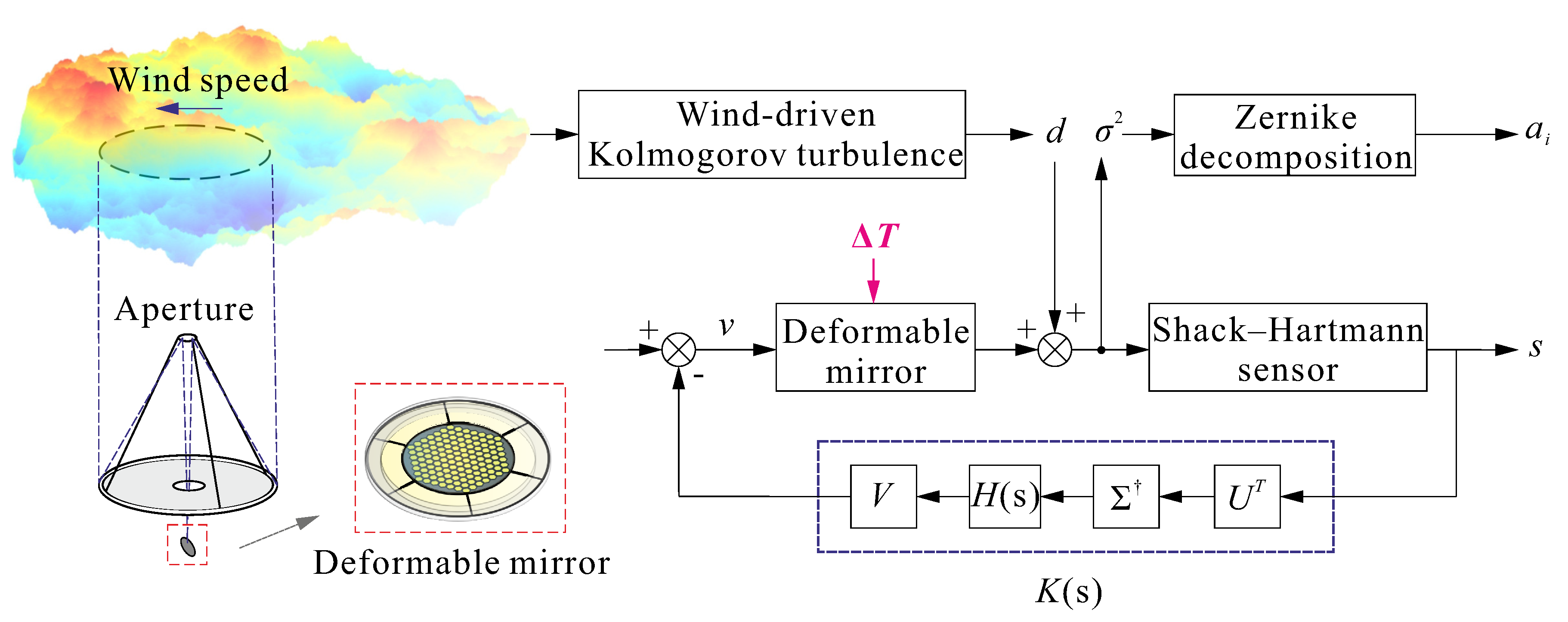
The control system is based on the assumption that the DM behaves in a quasi-static manner. The block diagram is represented in Figure 3; the disturbance d consists of a frozen Kolmogorov turbulent screen transported by the wind. The performance is measured by the residual phase variance error and its Zernike expansion. The feedback loop consists of an SVD compensator K ( s ) = V H ( s ) Σ U T , where H ( s ) 
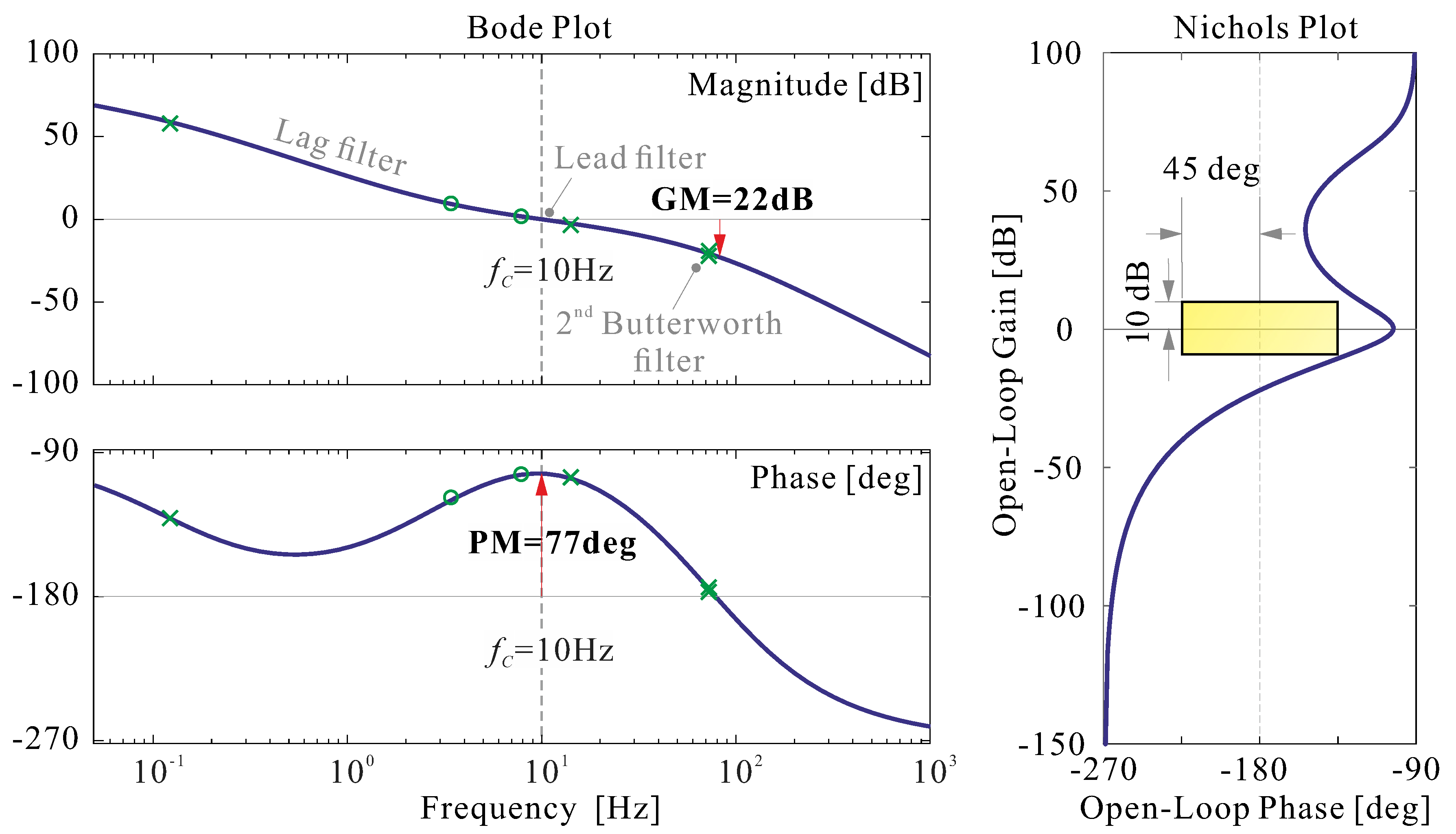
provides an adequate disturbance rejection and stability margin. H ( s ) may be a scalar function if the same loop shaping is applied to all the SVD modes, as in this study (Figure 4).
In reality, however, the deformable mirror does not behave quasi-statically but dynamically. The control approach is legitimate if the crossover frequency of the compensator is very small compared to the resonance frequency of the DM, f c f 1 .
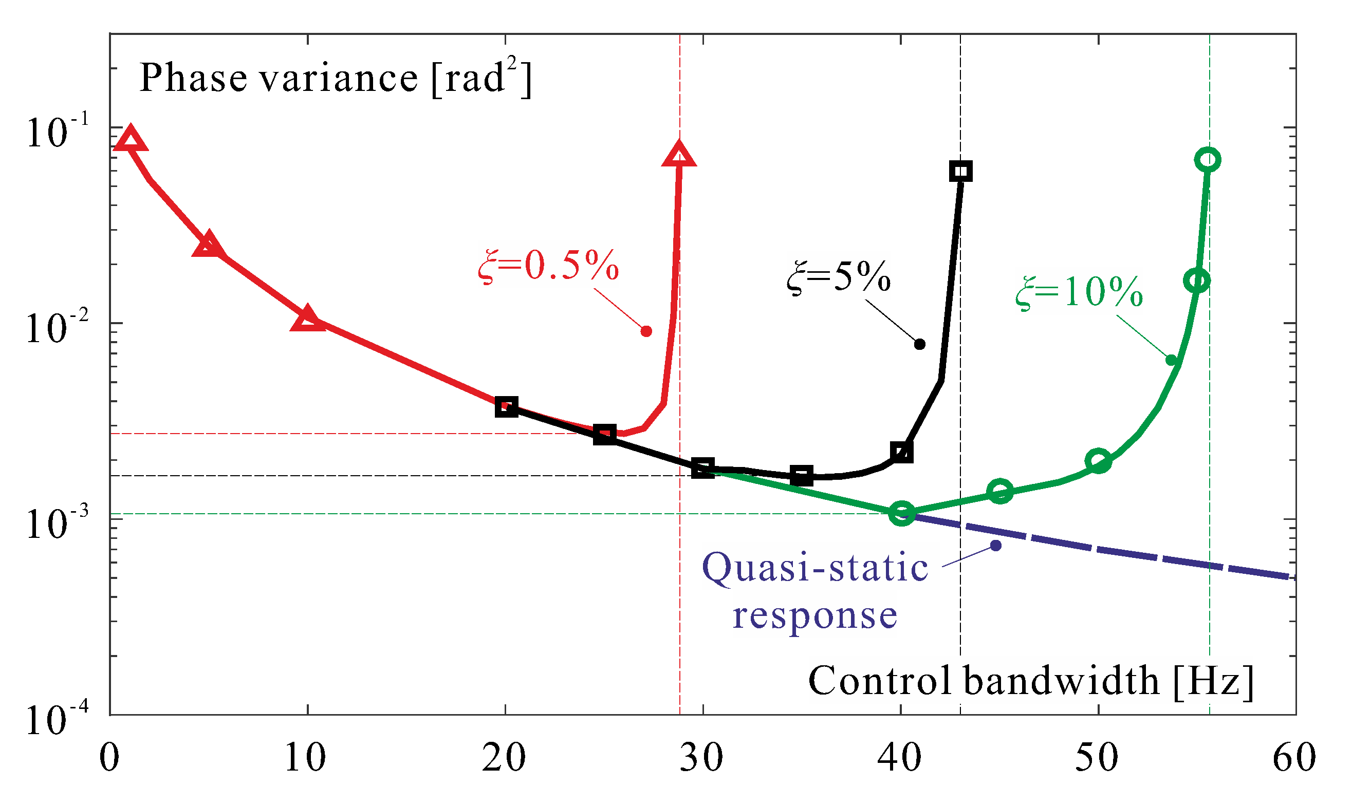
However, as the control bandwidth increases, the dynamic part of the mirror response will become more significant and will interfere with the controller, especially if the structural damping is low. This is illustrated in Figure 5, which shows the evolution with the control bandwidth (measured here by the crossover frequency f c ) of the normalized phase variance residual error when the tip-tilt is removed, for various values of the structural damping ξ . The open-loop residual error is σ 2 = 0.134 ( D / r 0 ) 5 / 3 ; the curves were obtained with a time-history analysis including the SH sensor and a dynamic model of the mirror; the compensator is that of Figure 4. The phase variance corresponding to a quasi-static response is shown in dashed lines. For low values of the crossover frequency f c , the results of the dynamic and the quasi-static analyses are identical, but when f c increases, the dynamic response of the mirror tends to deteriorate the phase error because of the contribution of the flexible modes of the mirror; for larger values of f c , the system becomes unstable. One sees that the phase error deterioration occurs for values of f c much below the first resonance of the mirror, f 1 = 208.9 Hz in this case, and that it depends strongly on the structural damping ξ of the mirror.

3. Thermal Deformations, Tip-Tilt Control

Because of the difference in the coefficient of thermal expansion (CTE) between the substrate (SiC in this case) and the PZT layer (
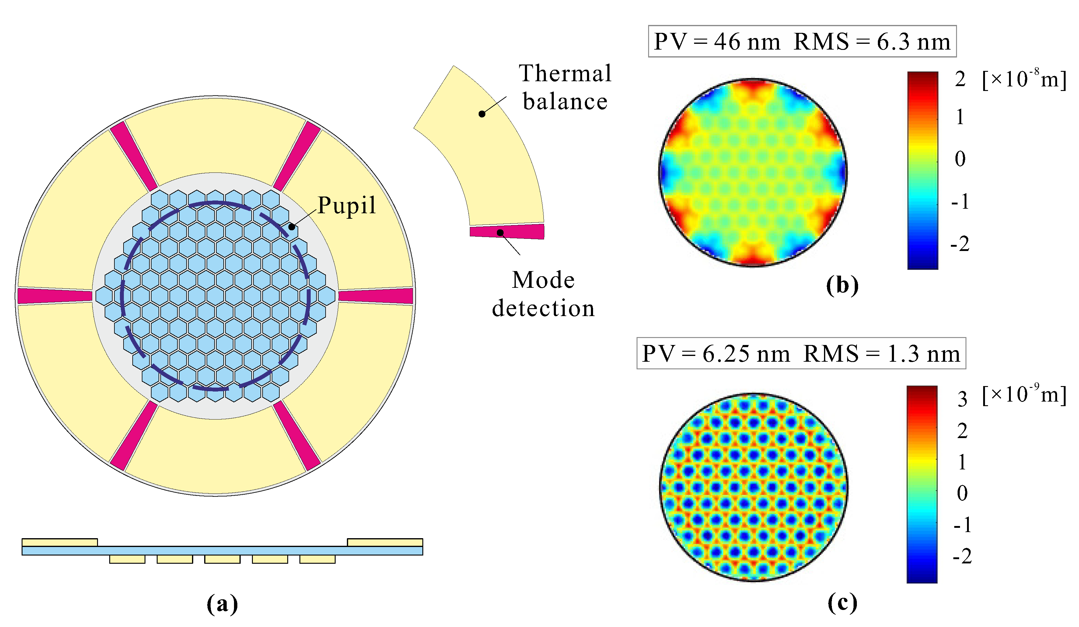
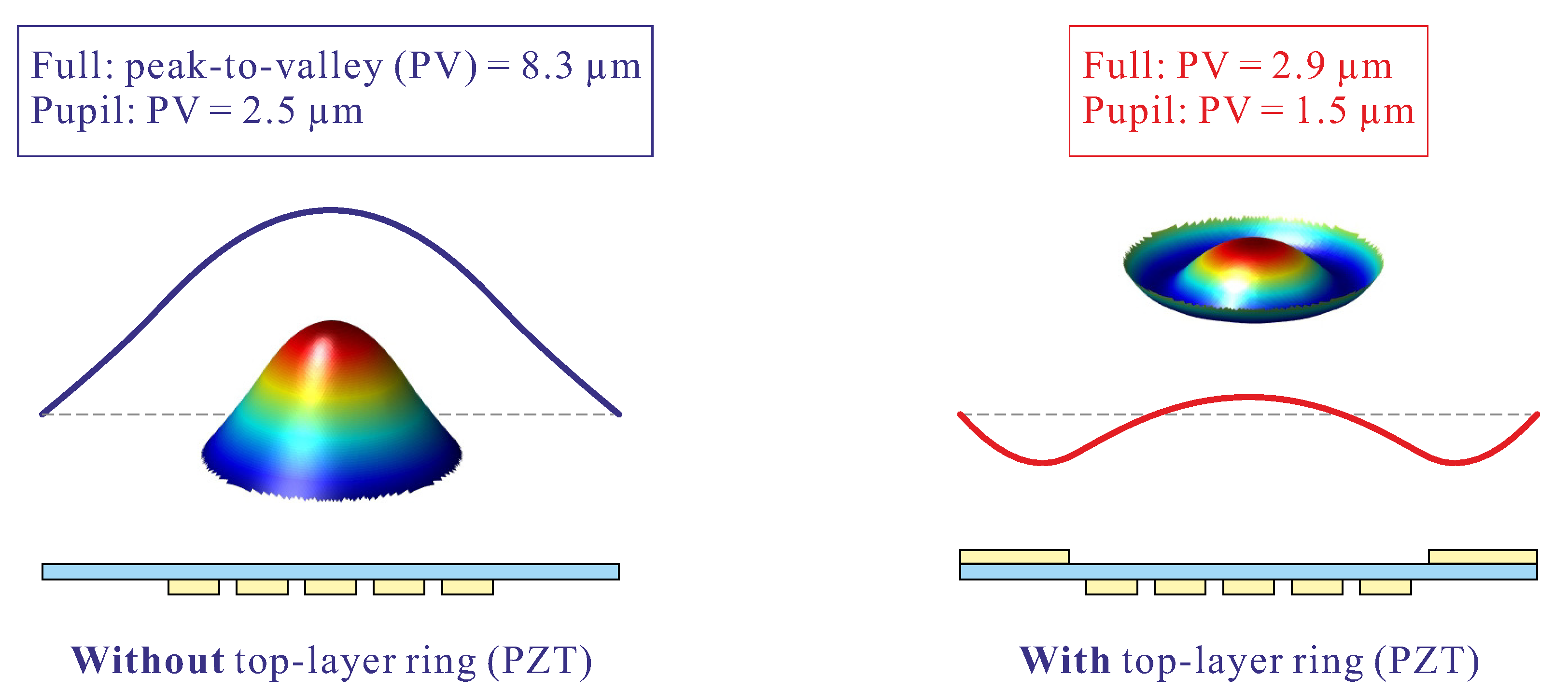
Table 1), unimorph DMs are thermally unbalanced; the situation is improved when the outer ring is added on the front side of the mirror, as illustrated in Figure 6 for a temperature variation of Δ T = 15 K; one sees that the piston term is strongly reduced, but significant deformations remain in the pupil.
However, one can use the PZT ring on the front side to compensate the thermal deformations actively; to this end, it is partitioned into 6 sectors (Figure 7a), and each sector has two electrodes, a large one used as actuator for thermal balance and a small one used as a sensor for mode detection, as discussed later in the paper. Only the large electrode is concerned with the active thermal control. Figure 7b shows the residual surface figure error in the pupil when a voltage of V r i n g = 33.6 V is applied to the 6 ring actuators (all finite element modeling of piezoelectric plates was done in the software SAMCEF [8]). It can be further reduced if the honeycomb electrodes in the central part of the back side are also used for thermal control (Figure 7c). If the front-side ring actuators are introduced in the Jacobian J, the thermal control is integrated with atmospheric turbulence in the shape control (Figure 3). In Figure 7c, the residual surface figure error consists of an array of dimples; their amplitude is related to the gap between the electrodes [9].

3.1. Control Authority

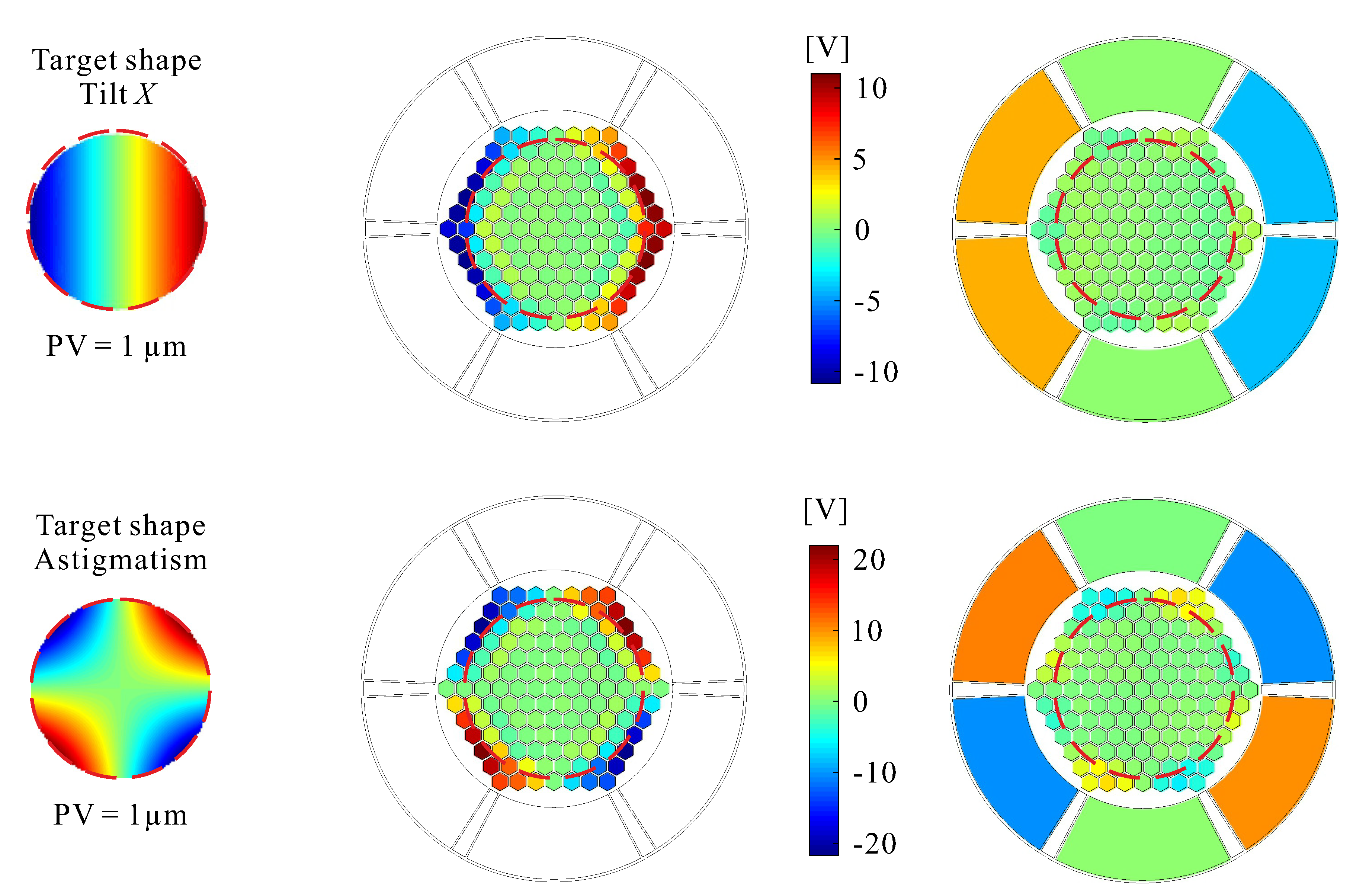
In addition to allowing a precise thermal control of the mirror, the front-side actuators bring additional authority to the control of the low-order Zernike modes, as illustrated in Figure 8 and Table 2, which compare the situation where the optical modes are controlled with the honeycomb actuators in the central part alone with that where the central actuators are used jointly with the front-side ring actuators. The voltage range is defined as Δ V = V m a x V m i n to produce the optical mode with a peak-to-valley (PV) displacement of 1 μm; all calculations are done with damped least squares with a damping coefficient α = 10 8 .

3.2. Tip-Tilt Control

The one-axis tilt angle variance is given by [1]
θ 2 = 0.182 ( D / r 0 ) 5 / 3 ( λ / D ) 2 ,
with the assumed values of D = 5 m, r 0 = 79 cm, and λ = 2.2 μm, θ = 8.75 × 10 7 rad. It follows that the RMS value of the deformable mirror is
θ D M = θ 2 D D p u p i l = 2.19 × 10 5 rad ,
where D p u p i l = 0.1 m is the pupil diameter of the AO mirror. This leads to a peak-to-valley amplitude of 2.19 μm. Referring to Table 2 and Figure 8 showing the voltage map needed to achieve a PV of 1 μm, one sees that this amplitude is well within the capability of the AO mirror when the front-side ring actuator is used, reducing the need for a dedicated tip-tilt mirror.

4. Active Damping

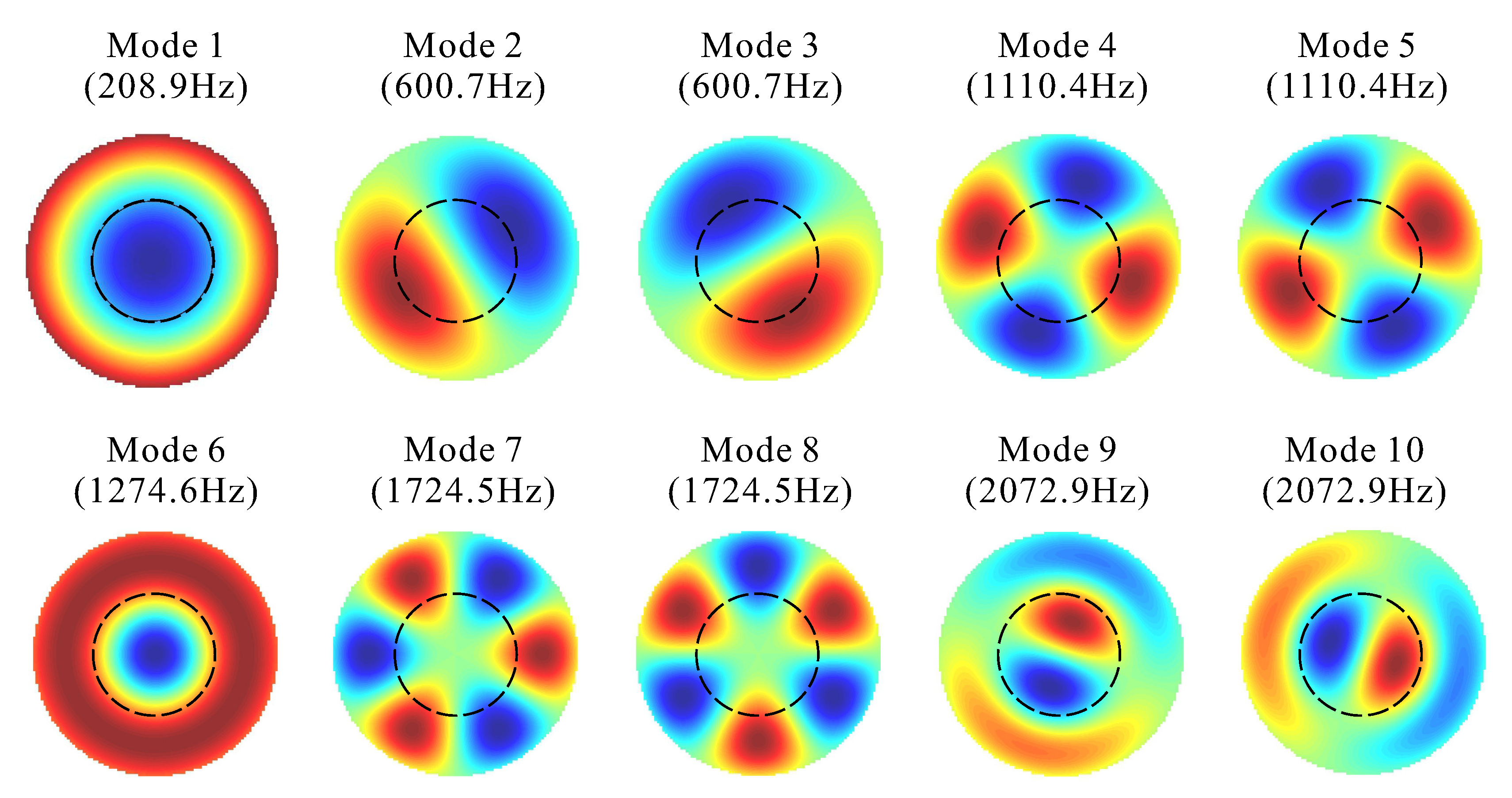
Figure 9 shows the vibration mode shapes and natural frequencies of the AO mirror of Figure 1; the low-frequency modes, if their damping is low, may interfere with the SVD controller and degrade the image quality (Figure 5). A strategy for active damping has been proposed in [4], based on ideas first proposed in [10]: The starting point is the dynamic input–output relationship between the input voltages of the actuators and the output signals (the slopes) from the SH sensor:
s = G ( s ) v , G ( s ) = S Φ · d i a g [ 1 s 2 + 2 ξ i ω i s + ω i 2 ] Φ T K a ,
where K a stands for the matrix relating the input voltages to the equivalent piezoelectric forces acting on the mirror [8,11], Φ is the matrix of mode shapes (normalized to a unit modal mass), and S is the matrix relating the SH output to the deflection modes of the mirror. ω i are the resonance frequencies and ξ i the modal damping of the various vibration modes. The size of G ( s ) was (450 × 127) in [4]; with the addition of the ring actuators and sensors, it becomes (456 × 133). Note that with these notations, the Jacobian reads
J = G ( 0 ) = S Φ · d i a g [ 1 ω i 2 ] Φ T K a .
If Φ ^ is the set of modes whose amplitude must be reconstructed (a small number of low-frequency modes), the matrices C = S Φ ^ and B = Φ ^ T K a may be constructed (either numerically or experimentally). The pseudo-inverses C and B may be computed (taking care of possible ill-conditioning—we will return to this below); if s is the output vector of the SH sensor (not to be mistaken with the Laplace variable s), the modal amplitudes of the reconstructed modes read
z ^ = C s = ( C T C ) 1 C T s .
A set of damping filters may be introduced to provide the selected modes with the appropriate active damping ξ i d :
D ( s ) = d i a g ( 2 ξ i d ω i s ) .
Finally, the modal control is projected on the control electrodes by the matrix B :
v = B D ( s ) C s ,
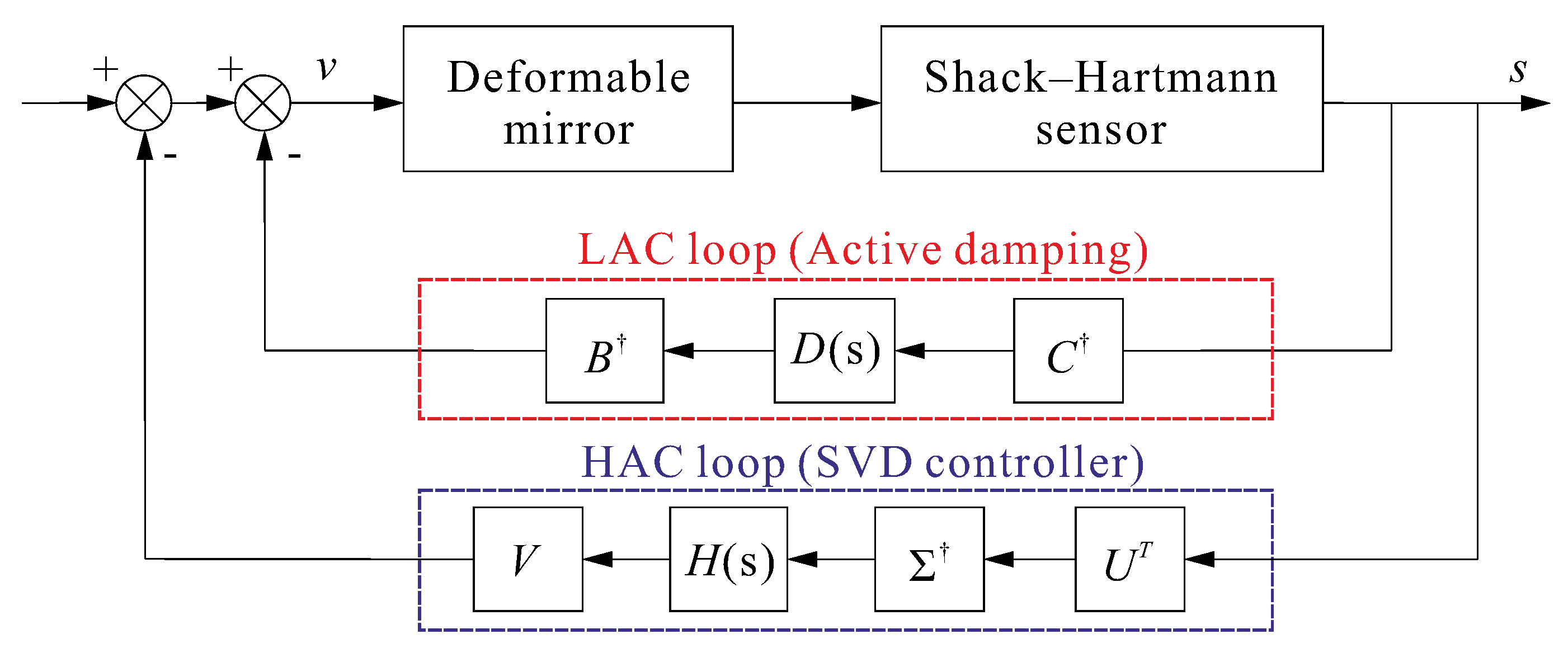
leading to the so-called HAC/LAC (high authority/low authority) control strategy of Figure 10.

Modal Sensor

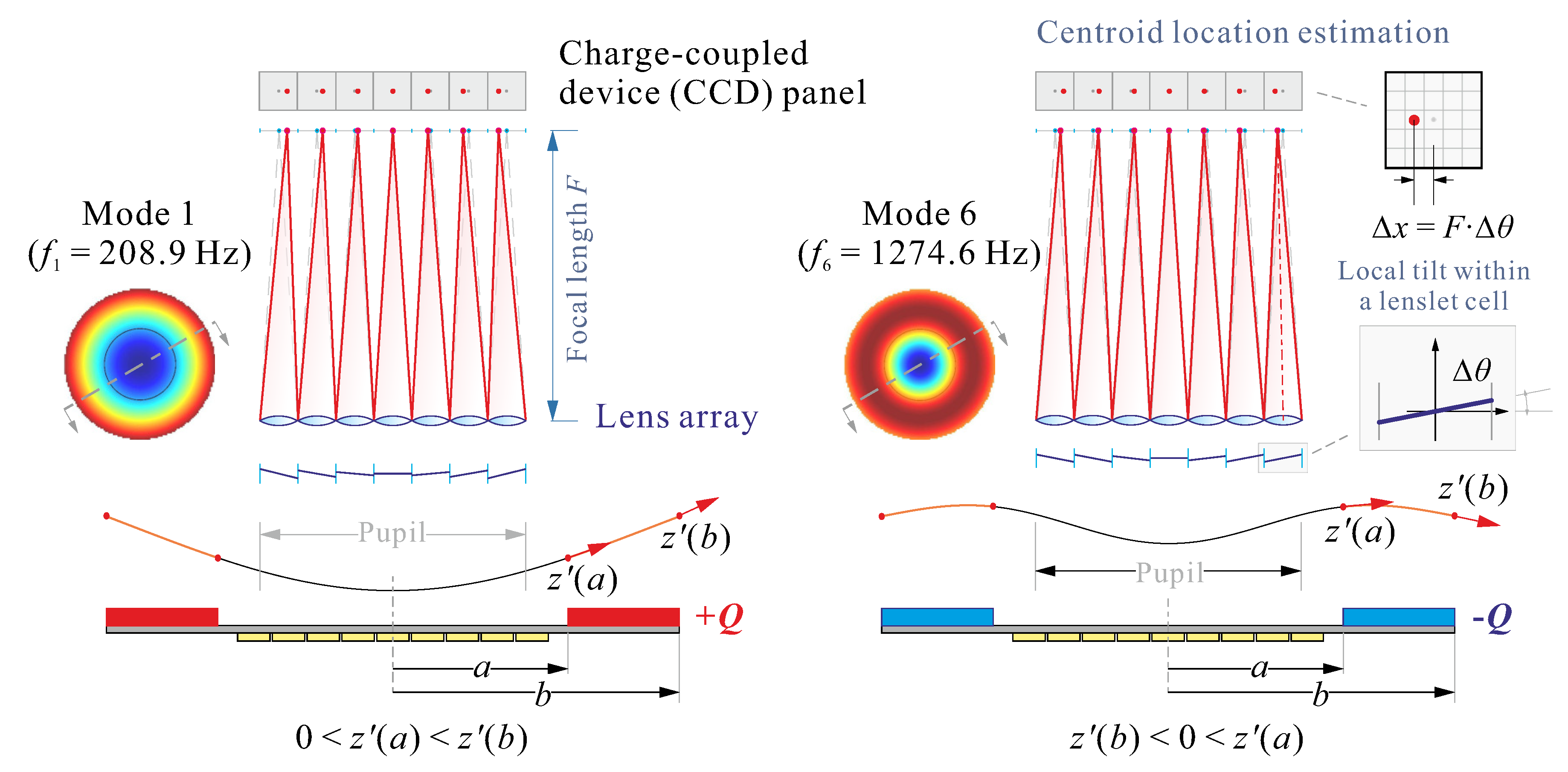
Although orthogonal over the entire mirror, the vibration modes are not orthogonal within the pupil, which covers only part of the mirror. Observing Figure 9, one sees that mode 1 and mode 6 have a very similar shape within the pupil, and similarly for modes 2 and 3 and modes 9 and 10. This brings ill-conditioning in the C matrix of the SH sensor, which may lead to the response of mode 6 being mistaken with that of mode 1. In Figure 9, one further observes that outside the pupil, mode 1 and 6 have radial curvatures of opposite signs, and similarly for modes 2 and 3 and modes 9 and 10. This suggests that this feature may be used to discriminate the modes and improve the conditioning of C.
To this end, 6 piezoelectric sensors are added outside the pupil on the front side of the mirror (in red in Figure 7a); because of their nearly rectangular shape, the sensor signal is nearly proportional to the average curvature in the radial direction [11], that is, the difference of slopes between the outer and the inner side of the sensor:
Q = g s a b z ( r ) d r = g s [ z ( b ) z ( a ) ] ,
where the sensor gain g s depends on the material properties, the electrode width and the charge amplifier gain. Figure 11 illustrates this situation for mode 1 and mode 6; one sees that the contribution of the piezoelectric sensor will be positive for mode 1 and negative for mode 6, while the contributions of the SH sensor will be similar.
Of course, combining sensors of different natures requires proper scaling. If C 1 refers to the SH sensor (measuring the slopes within the pupil) and C 2 refers to the 6 PZT sensors measuring the average radial curvature outside the pupil, the C matrix becomes
C = C 1 w C 2 ,
where 
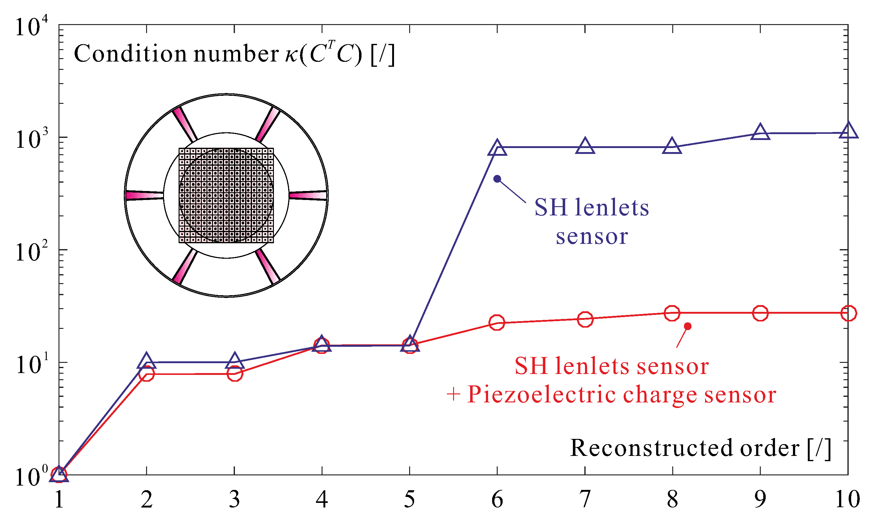
w is the scaling factor. The condition number κ ( C T C ) = σ m a x / σ m i n of C T C = C 1 T C 1 + w 2 C 2 T C 2 is minimum when C 1 T C 1 2 = w 2 C 2 T C 2 2 .
Figure 12 compares the condition number when the C matrix is based on the SH sensor alone with that when it combines the SH and the curvature sensors. No reduction is observed for the first 5 modes because they differ significantly inside the pupil; starting from mode 6, the combined sensor reduces the condition number by almost two orders of magnitude.
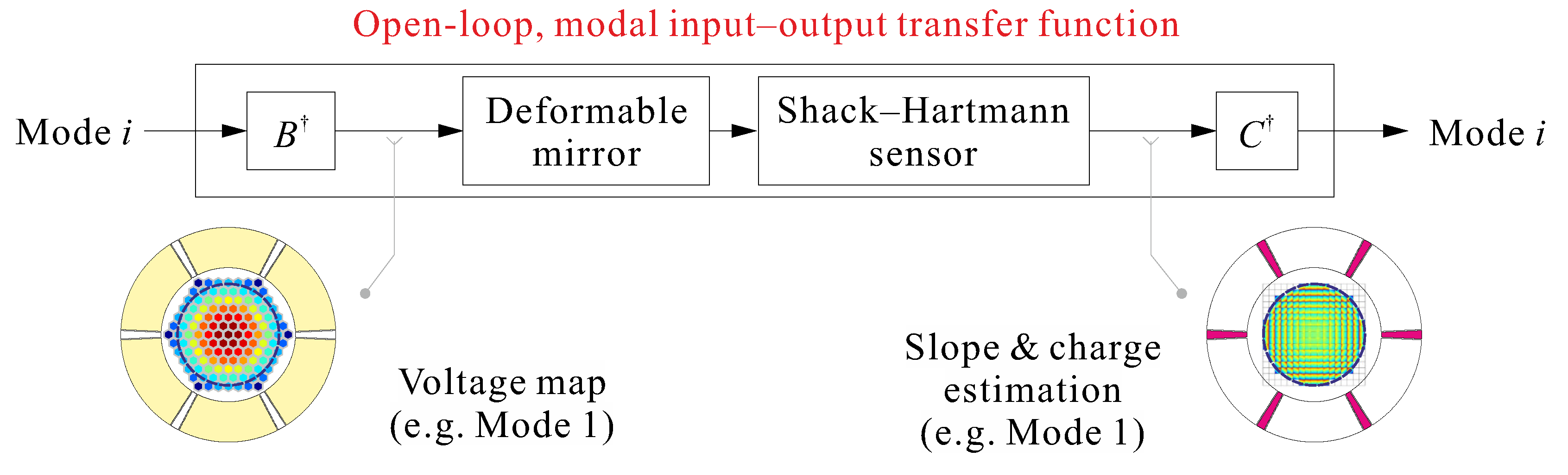
Figure 13 summarizes the open–loop modal input-output relationship for the LAC loop: The B matrix provides the scaling of the input voltages of the various electrodes in order to construct the appropriate excitation of mode i, and the C provides the modal filter to reconstruct the modal amplitude.

5. Conclusions

This paper proposes a simple and economical solution to manufacturing piezoelectric deformable mirrors for adaptive optics. The idea relies on using a ring of PZT material outside the pupil on the front side of the mirror; this ring is divided into sectors with two electrodes each, a large one used as actuator for thermal and shape control and a small one used as a sensor in order to improve the detection of the vibration modes in a modal filter. The proposed configuration has the following important features:
  • It allows a precise thermal control of the mirror (the thermal control is part of the shape control). Simulations show a residual PV of 6.25 nm for a temperature difference of 15 K.
  • It brings additional control authority on the low order Zernike modes, reducing the control budget of the central actuators. The configuration has enough authority to provide full control of the tip-tilt modes.
  • It allows applying a bias voltage to the shape control actuators in order to exploit their full range of actuation.
  • The critical vibration modes that can deteriorate the image quality because of their low structural damping may be damped actively with a minimum added complexity to the hardware and the control system.
The example presented here uses a honeycomb layout of electrodes, but the approach applies to any electrode layout (e.g., keystone layout).

Author Contributions

Conceptualization, K.W., D.A., and A.P.; software, K.W. and D.A.; writing–original draft preparation, A.P.; writing–review and editing, K.W. and A.P.; supervision, A.P.

Funding

This research received no external funding.

Conflicts of Interest

The authors declare no conflict of interest.

Abbreviations

The following abbreviations are used in this manuscript:
AOAdaptive optics
CTECoefficient of thermal expansion
DMDeformable mirror
ELTExtremely Large Telescope
ESOEuropean Southern Observatory
HACHigh authority control
LACLow authority control
PVPeak-to-valley
PZTLead zirconate titanate
RMSRoot mean square
SHShack–Hartmann
SiCSilicon carbide
SVDSingular value decomposition

References

  1. Tyson, R.K. Introduction to Adaptive Optics; SPIE Press: Bellingham, WA, USA, 2000. [Google Scholar]
  2. Madec, P.Y. Overview of deformable mirror technologies for adaptive optics and astronomy. In Proceedings of the SPIE Astronomical Telescopes + Instrumentation, Amsterdam, The Netherlands, 1–6 July 2012; p. 8447. [Google Scholar]
  3. European Southern Observatory. The E-ELT Construction Proposal; ESO: Garching bei München, Germany, 2011. [Google Scholar]
  4. Wang, K.; Alaluf, D.; Mokrani, B.; Preumont, A. Control-structure interaction in piezoelectric deformable mirrors for adaptive optics. Smart Struct. Syst. 2018, 21, 777–791. [Google Scholar]
  5. Alaluf, D.; Bastaits, R.; Wang, K.; Horodinca, M.; Martic, G.; Mokrani, B.; Preumont, A. Unimorph mirror for adaptive optics in space telescopes. Appl. Opt. 2018, 57, 3629–3638. [Google Scholar] [CrossRef] [PubMed]
  6. Hagood, N.W.; von Flotow, A. Damping of structural vibrations with piezoelectric materials and passive electrical networks. J. Sound Vib. 1991, 146, 243–268. [Google Scholar] [CrossRef]
  7. Buss, S.R. Introduction to inverse kinematics with jacobian transpose, pseudoinverse and damped least squares methods. IEEE Robot. Autom. 2004, 17, 1–19. [Google Scholar]
  8. Piefort, V. Finite Element Modeling of Piezoelectric Active Structures. Ph.D. Thesis, Actives Structures Laboratory, Université Libre de Bruxelles, Brussels, Belgium, 2001. [Google Scholar]
  9. Bastaits, R.; Alaluf, D.; Horodinca, M.; Romanescu, I.; Burda, I.; Martic, G.; Rodrigues, G.; Preumont, A. Segmented bimorph mirrors for adaptive optics: segment design and experiment. Appl. Opt. 2014, 53, 6635–6642. [Google Scholar] [CrossRef] [PubMed]
  10. Meirovitch, L.; Baruh, H. The implementation of modal filters for control of structures. J. Guid. Control Dyn. 1985, 8, 707–716. [Google Scholar] [CrossRef]
  11. Preumont, A. Vibration Control of Active Structures, an Introduction, 4th ed.; Springer: Cham, Switzerland, 2018. [Google Scholar]
Figure 1. Adaptive optics (AO) mirror baseline configuration used in the simulations. The left side shows the piezoelectric ceramic (PZT) actuator array with honeycomb electrodes, and the right side shows the square lenslet array of the Shack–Hartmann (SH) sensor and the ring of PZT material used for inductive shunt damping [4].
Actuators 08 00075 g001
Figure 2. L-curve for the damped least squares: Voltage range Δ V vs. root mean square (RMS) residual surface figure error for various values of the damping coefficient α .
Actuators 08 00075 g002
Figure 3. Block diagram of the control system. The input–output relationship is s = J v . The feedback loop consists of the singular value decomposition (SVD) controller K ( s ) = V H ( s ) Σ U T . The disturbance d consists of a frozen Kolmogorov turbulent screen transported by the wind. The performance is measured by the Zernike expansion of the residual error; σ 2 is the phase variance error.
Actuators 08 00075 g003
Figure 4. Compensator H ( s ) , normalized to f c = 10 Hz. It consists of an integrator, a lag filter, a lead filter, and a Butterworth second-order filter; the position of the poles and zeros are indicated on the Bode plots (left). The bandwidth may be adjusted by translating the Bode plots along the frequency axis until the proper crossover frequency f c is reached. This leaves the Nichols plot (right) unchanged.
Actuators 08 00075 g004
Figure 5. Normalized phase variance residual error, σ 2 ( D / r 0 ) 5 / 3 (with tip-tilt removed) when the SH and the dynamics of the mirror are included in the analysis, as a function of the crossover frequency f c of the controller of Figure 4. The deterioration of the performance for larger f c is highly dependent on the structural damping ξ . The first natural frequency of the mirror is f 1 = 208.9 Hz.
Actuators 08 00075 g005
Figure 6. Thermal deformations induced in the mirror by Δ T = 15 K; the substrate is SiC. Left: without PZT ring on the front side. Right: with PZT ring (200 μm).
Actuators 08 00075 g006
Figure 7. Active compensation of thermal deformations. (a) Design configuration showing the outer ring divided into 6 sectors with two electrodes each: A larger one is used as actuator for thermal control, and a smaller one is used as curvature sensor for mode detection for active damping. (b) Residual surface figure error in the pupil when the 6 ring actuators are used. (c) Residual surface figure error in the pupil when using the honeycomb and the 6 ring actuators for thermal control.
Actuators 08 00075 g007
Figure 8. Comparison of the control voltages necessary to achieve a PV = 1 μm in the pupil. Left: honeycomb actuators alone. Right: honeycomb + front ring actuators. Top: X-Tilt. Bottom: Z5 astigmatism. The voltage ranges and the RMS residual errors are reported in Table 2.
Actuators 08 00075 g008
Figure 9. Vibration mode shapes and natural frequencies of the AO mirror. The pupil is represented in dashed lines. Notice the possible confusion between mode 1 and mode 6 within the pupil, and similarly between modes 2–3 and 9–10.
Actuators 08 00075 g009
Figure 10. High authority/Low authority (HAC/LAC) strategy for active damping of the mirror. The shape control loop (HAC) is supplemented by a modal active damping (LAC) of the critical low frequency modes.
Actuators 08 00075 g010
Figure 11. Cross-section in the mirror illustrating the contribution of the piezoelectric sensor for mode 1 and mode 6. The sensor signal is Q = g s [ z ( b ) z ( a ) ] and is positive for mode 1 and negative for mode 6. The SH sensor produces similar signals in the central part of the mirror.
Actuators 08 00075 g011
Figure 12. Condition number of κ ( C T C ) as a function of the reconstructed order of the modes, for the SH sensor alone and the sensor combining the SH with 6 PZT radial curvature sensors outside the pupil.
Actuators 08 00075 g012
Figure 13. Block diagram of the modal input–output transfer function (illustrated for mode 1).
Actuators 08 00075 g013
Table 1. Material data used in the simulations
SiCPZT
Young’s modulus Y [ GPa ] 47662
Density ρ [ kg / m 3 ] 32107800
Poisson’s ratio ν [ / ] 0.190.34
Coefficient of thermal expansion CTE [ × 10 6 / K ] 5.124
Max. electric field [V/m]- 2 × 10 6
Piezoelectric constant d 31 [pC/N]- 180
Table 2. Comparison of the control authority for the low-order Zernike modes with a PV amplitude of 1 μm. Δ V = V m a x V m i n . Left: The central actuators on the back are used alone. Right: They are used jointly with the ring actuators on the front side.
Without Front-Side Ring PZTWith Front-Side Ring PZT
Δ V [V]Err. RMS [nm] Δ V [V]Err. RMS [nm]
Z2 Tilt X24.62.19.40.26
Z3 Tilt Y26.82.0410.90.25
Z4 Defocus35.56.914.12.7
Z5 Astigmatism (O)43.93.920.61.2
Z6 Astigmatism (V)41.34.018.11.2
Z7 Coma (V)61.69.035.14.0
Z8 Coma (H)58.29.039.34.1
Z9 Trefoil (V)66.56.432.10.6
Z10 Trefoil (O)49.95.849.55.8
Z11 Spher. Aber.105.135.373.023.5
Z12 Sec. Astig. (V)73.719.254.711.2
Z13 Sec. Astig. (O)76.918.949.011.1
Z14 Tetrafoil (V)82.79.277.58.5
Z15 Tetrafoil (O)83.89.269.88.5

