Abstract
Passively magnetically stabilized degrees of freedom yield the benefit of reduced complexity and therefore costs. However, the application of passive magnetic bearings (PMBs) also features some drawbacks. The poor damping capability leads to exaggerated deflection amplitudes when passing the resonance speeds of the applied system. This results in the necessity of external damping. Complying with the goal of costs and complexity, viscoelastic materials offer a suitable solution. However, these materials show high frequency and temperature dependent properties which induce the necessity of a proper model. Thus, the design of systems, as presented in this paper, requires accurate modeling of the dynamic behavior including the nonlinear characteristic of damping elements to predict the system displacements. In the investigated setup only two degrees of freedom remain to be controlled actively. These are the axial rotation and the axial position of the rotor which are controlled by the motor and an active magnetic axial bearing (AMB). This article focuses on the rotor dynamic modeling of a radial passively magnetically stabilized system especially considering the nonlinear behavior of viscoelastic damping elements. Finally, the results from the analytic model are verified by measurements on a manufactures test system.
1. Introduction
Nowadays, the number of applications for rotating machines is huge. In general, therefore, the rotor is supported with traditional mechanical ball or slide bearings, which feature the drawback of applied lubricants, mechanical friction and resulting wear. Magnetic bearing technology is a contemporary research area that can be described as relatively young. The principle is based on the generation of suspension forces by magnetic fields which allows a contact-free operation of the motor. Magnetic bearings have their advantages especially in areas that require high-purity operation or very high speeds. These applications can be found in machining technology as milling spindles, in vacuum technology as turbomolecular pumps, in medical applications as blood pumps as well as in flywheel accumulators [1,2] and gas compressors. Additionally, the aspect of service life is superior, due to the fact that in magnetically suspended systems it is only determined by the electronic components.
In addition, as is usual in the field of magnetically stabilized system design, the costs play a very important role. The high complexity compared to standard ball bearings has thereby a major impact on the price. With reference to fully actively stabilized systems, which are still applicable in commercial areas, investigations regarding passively stabilized systems are rare [3,4]. The first works on passive permanent magnetic (PM) ring bearings can be found in 1976 [5]. In 1981, Yonnet [6] characterized the different possible bearing principles for the first time. Marinescu and Yonnet presented the basics for dimensioning of PM ring bearings in 1979 and 1980 [7,8]. A great advance in analytical computability was presented by Lang [9] for attractive ring bearings. An extension to repulsive ring bearings was provided by Jungmayr [10]. Today the filed of applications for passive PM ring bearings include spinning centrifuges, turbomolecular pumps, flywheels and fully magnetically stabilized fans.
The use of passive magnetic bearings (PMB) offers a very interesting approach to reduce the complexity of the magnetic bearing to a minimum and thereby makes the application attractive for cost-sensitive areas. Hence, in such systems the demand for power electronics and position sensors is minimized. The passive bearing arrangement by means of permanent magnets has to be emphasized, as it enables a nearly loss-free bearing arrangement with very little effort. Furthermore it features the advantage of easy determination of stiffness and static load carrying capacity. The determination of the stiffness of permanent magnet bearings can be performed analytically in arrangements without ferromagnetic material. For applications with ferromagnetic material finite element calculations are necessary. However, a major disadvantage of permanent magnetic bearings is the extraordinary low damping of the stabilized degrees of freedom, which lead to exaggerating deflections when passing rigid body resonances during a run-up process. So additional damping has to be induced into the system [11,12,13,14]. Especially systems with large unbalances need a very precise consideration of the dynamic behavior.
A possibility to provide damping is offered by viscoelastic materials which meet the targets of low costs and simplicity. Viscoelastic materials are currently being used in various applications for damping and suppression of vibrations. The selection of the damping material itself is often empirical. One reason for this lies in the complex dynamic behavior of this type of materials. In most cases the stiffness and damping of elastomers feature a high dependency on the excitation frequency and temperature. Using viscoelastic materials it is no longer possible to actively influence the system dynamics subsequently. Thus, a precise consideration of the material characteristics is necessary. This implies an exact knowledge of the overall system, especially the rotordynamic behavior, to ensure proper operation. Occurring deflections, due to the rotor dynamics, have to meet certain restrictions, to avoid contact between the rotor and the stator. This requires the derivation of the systems equations of motion and a proper model of the frequency-dependent damping elements behavior.
The concept examined in this paper is based on an industrial application, which is located in the area of mass production. With a large number of manufactured systems the price plays a decisive role. Thus, only system concepts come into consideration, which can drastically reduce costs. The avoidance of actively stabilized degrees of freedom and the resulting hardware savings (electronics, sensor technology, bearing coils) are crucial. Concepts with passively magnetically stabilized degrees of freedom are favorable due to their simplicity and low costs. However, a solution can only be achieved if the above-mentioned problems of damping can be solved in a cost-effective way. Although the modelling of viscoelastic damping elements is very complex, it offers an approaches to set up a proper system description.
The aim of this work is the design and optimization of a low-cost magnetic bearing drive system taking into account the special boundary conditions of the application. The high reliability of the concept is to be demonstrated, helping to implement contactless bearings in the industrial field more often.
In Section 2 the system setup and components are described. Section 3 determines the viscoelastic material model followed by Section 4, where the derivation of the equations of motion is presented. With the derived model an optimization is performed in Section 5. Finally, the optimized system is verified by measurements in Section 6.
2. System Setup
Based on the application considered, the rotor features a vertical alignment. The speed range is 10.000–30.000 rpm, which, however, is constantly interrupted. Hence, a frequent start and stop of the system is demanded. A very critical point are unbalances, which will lead to high deflections in the passive bearings. These unbalances occur mainly due to constantly changing additional process masses, which are attached to the rotor during operation. Thereby the unbalance maximum is defined by a value of 20 gmm and can be applied to the rotor at any position. The drive system itself can be balanced in order to reduce the unbalance to a minimum. However, the unbalance of the process mass must be taken as the occurring unbalance. Especially in connection with a PMB concepts, this represents an immense challenge and requires an exact consideration of the damping elements.
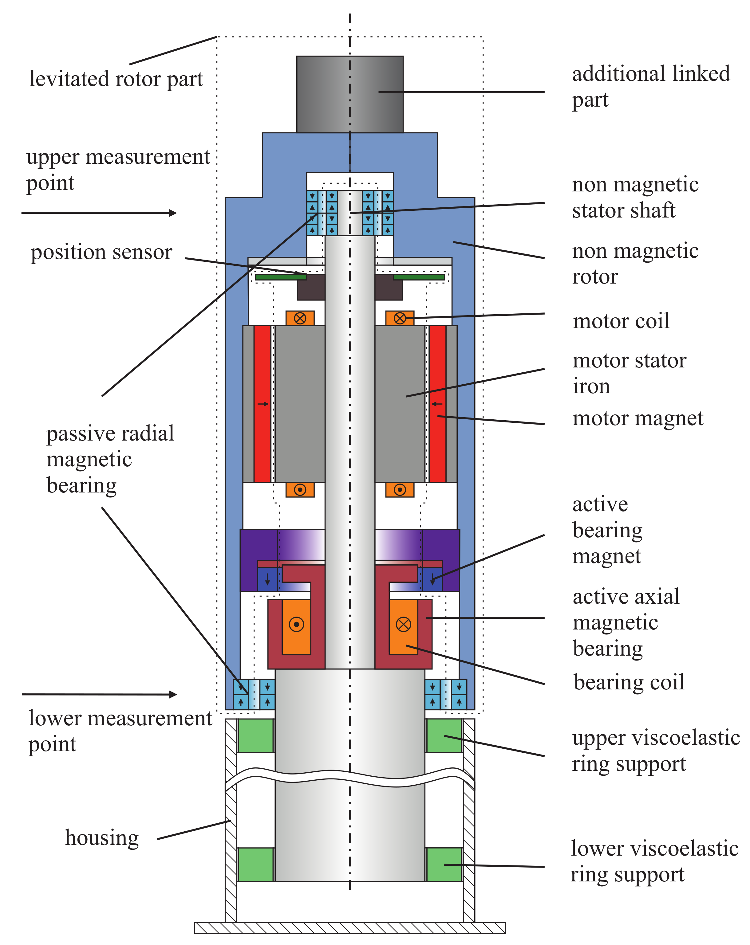
Geometric restrictions exist on the outer diameter of the rotor which is given by a maximum value of 42 mm. This requires a very compact design of the system. The limited space conditions lead to a stacked vertical construction. Figure 1 shows the setup of the considered magnetically levitated system.

Figure 1.
Setup of the investigated system.
In the shown configuration, the radial deflections and the tilting are stabilized by two radial permanent magnet bearings. These ringbearings are of repulsive type and use axial magnetized magnets, which are easy to produce and lower the costs for the bearings. Furthermore, this configuration offers the opportunity of magnet stacking [15] to achieve higher bearing stiffness with the same cross section and thereby simplifies the rotordynamic design procedure.
Without ferromagnetic material near the PM the stabilizing radial stiffness of the bearings can be analytically calculated [9]. This drastically simplifies the bearing design for the prototype, because no finite element simulations are necessary. Due to Earnshaw’s theorem [16], which is adapted for passive ring bearings in [17], the destabilizing axial stiffness of the bearings is given by
where describes the stabilizing radial stiffness.
Hence, at least one direction needs to be stabilized actively. In between the active axial bearing, the motor and the position sensor [18,19] are placed. As damping elements viscoelastic ring elements are used. These elements are located between the stator and the system housing. The viscoelastic ring elements are placed and glued in two aluminum rings to allow easy mounting. With this concept and the right dimensioning, it is possible to achieve improved dynamic system properties [20]. The rotor is designed as an exterior rotor. In principle, interior rotor concepts are also possible, but it should be avoided that the critical bending Eigenfrequencies of the rotor occur within the speed range. Moreover, the supporting rod of the motor, the active bearing and the sensor system become thin. Hence, the flexible behavior might as well affects the dynamics of the system. However, the considered motor is constructed with a slotted stator and ferrite magnets for cost reduction. As AMB a reluctance force bearing is used, whose force density is higher compared to a Lorenz force bearing.
3. Model of the Viscoelastic Behavior
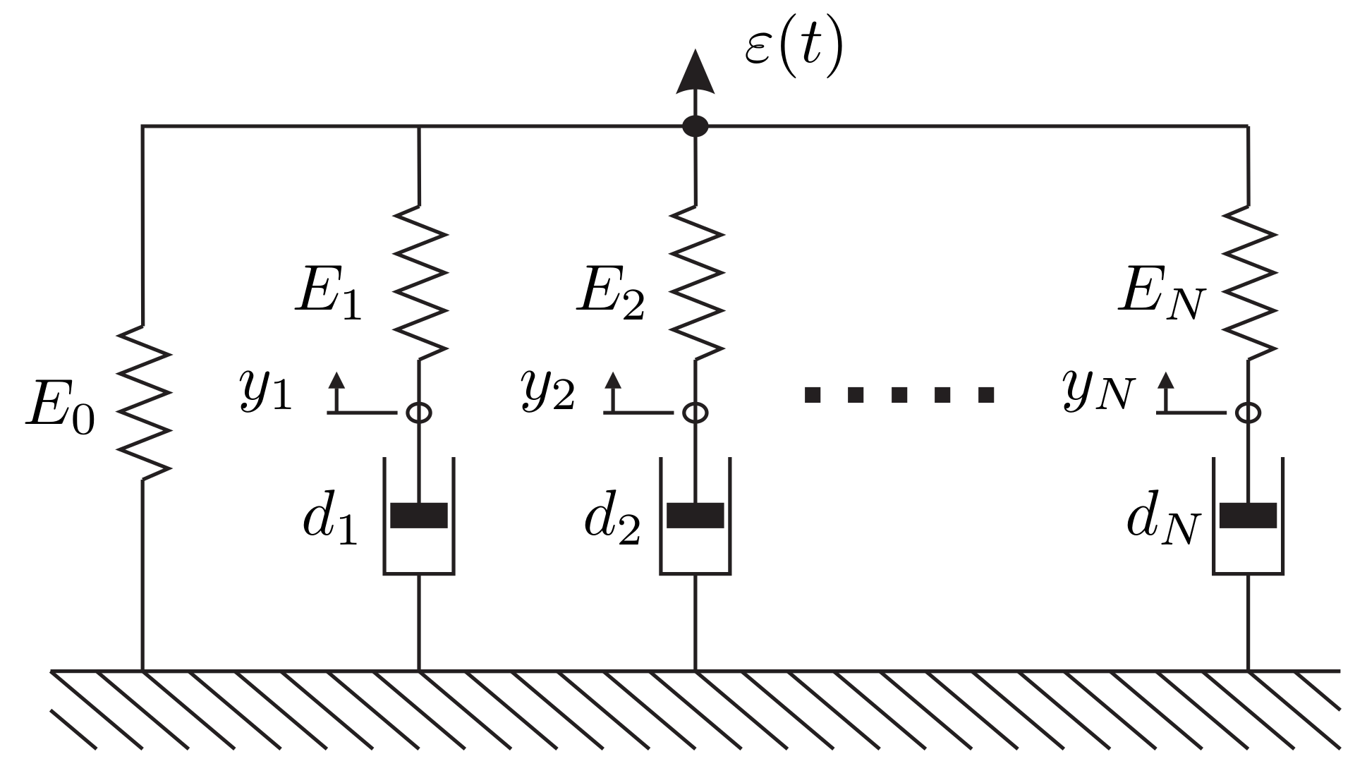
Viscoelastic materials feature a frequency dependent behavior of the stiffness and damping values. To describe the characteristics of such materials often a generalized Maxwell model is used [21,22,23]. As shown in Figure 2, such a model consists of a single spring with the equilibrium modulus and several Maxwell units in parallel. This spring describes the material response after infinite time. Each Maxwell consists of a single spring and a single damper in series, reproducing the frequency dependency by adding different time constants . So a quasi non-linear behavior can be represented by superposing linear elements. For harmonic excitations in the frequency domain a representation of the generalized Maxwell model with a complex modulus
is useful. Thereby, stands for the storage module and for the loss module. The quotient gives the loss factor

Figure 2.
Maxwell-Modell of the viscoelastic materials dynamic behavior representing one viscoelastic ring support.
Converted to the Prony parameters [24] of the generalized Maxwell model the components of the complex modulus result in
and
with the time constants .
In addition, the Maxwell model uses N inner states . A main advantage of this model is its easy integration as it can be described by a system of linear differential equations.
Determination of Material Parameters
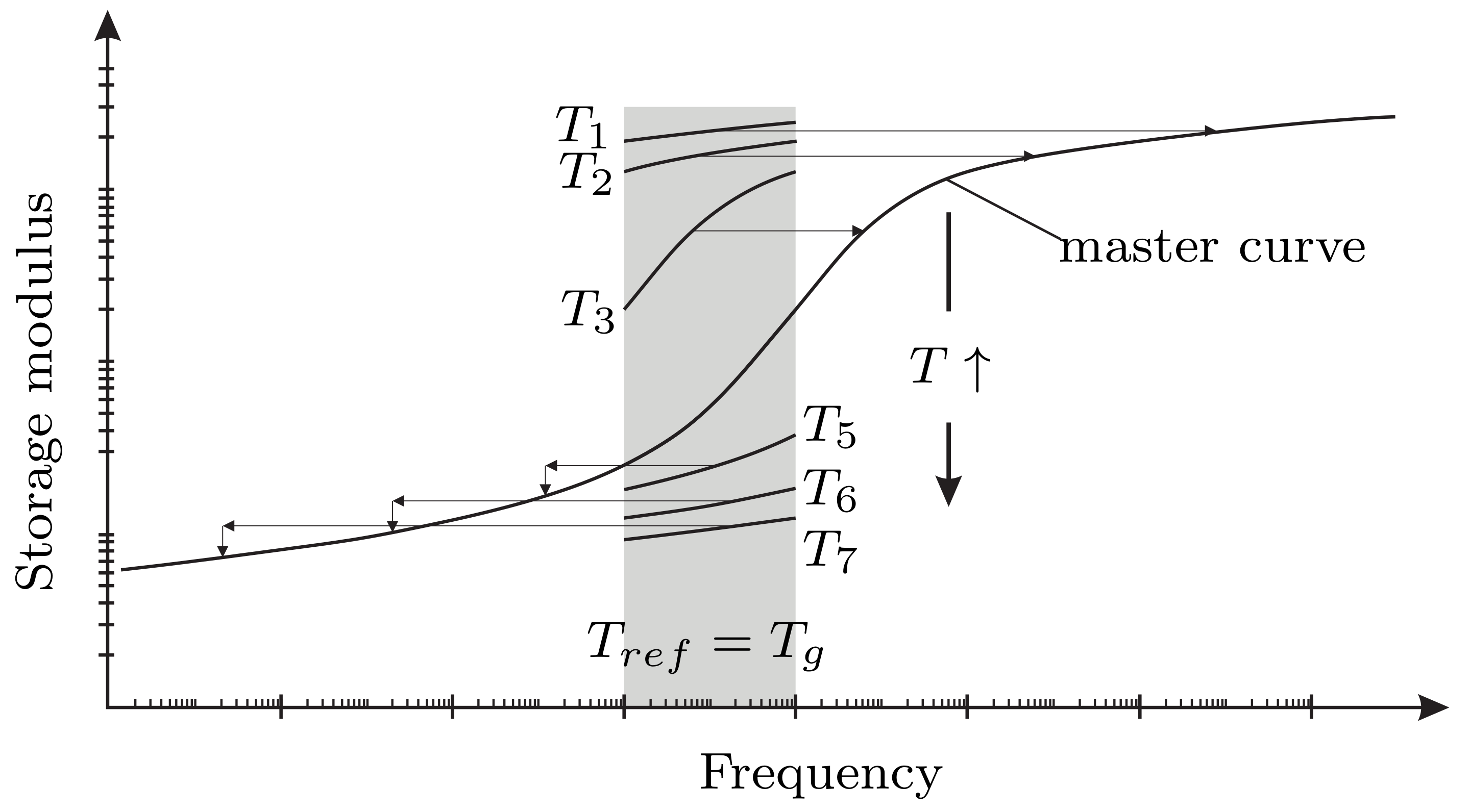
To describe the thermo-viscoelastic behavior usually master curves are used [24]. Thereby, the theory of temperature-time-correspondence is applied to combine measurements at different temperatures and draw conclusions for other frequencies. The basic approach is depicted in Figure 3.
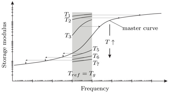
Figure 3.
Application of the temperature-time-correspondence.
In theory [25] viscoelastic material shows the same storage modulus for a certain temperature and frequency as for a different temperature and a referring scaled frequency according
with the shift factor . With lower temperatures the storage modulus is increasing and falling with increasing temperatures. As only a limited frequency range can be measured, one measurement is not sufficient to represent the required frequency range. Hence, it is necessary to combine the measurements. The shift factors thereby perform a vertical shift of the measured data, so that a smooth overall mastercurve is resulting. If unfilled elastomers are used, the kinetic-theory-factor [25] has to be applied, which is obtained from the theory of entropy elasticity. The storage modulus is thereby horizontally shifted to the reference temperature using
with as measured temperature and as the glass transition temperature. The factor normalizes the specific volume at a temperature to the reference temperature . Therefore, the horizontal shift is only applied to temperatures lower than the glass transition temperature, which lies for technical elastomers normally far below zero degrees Celsius. The loss factor values are also shifted in that process as it is the quotient of and .
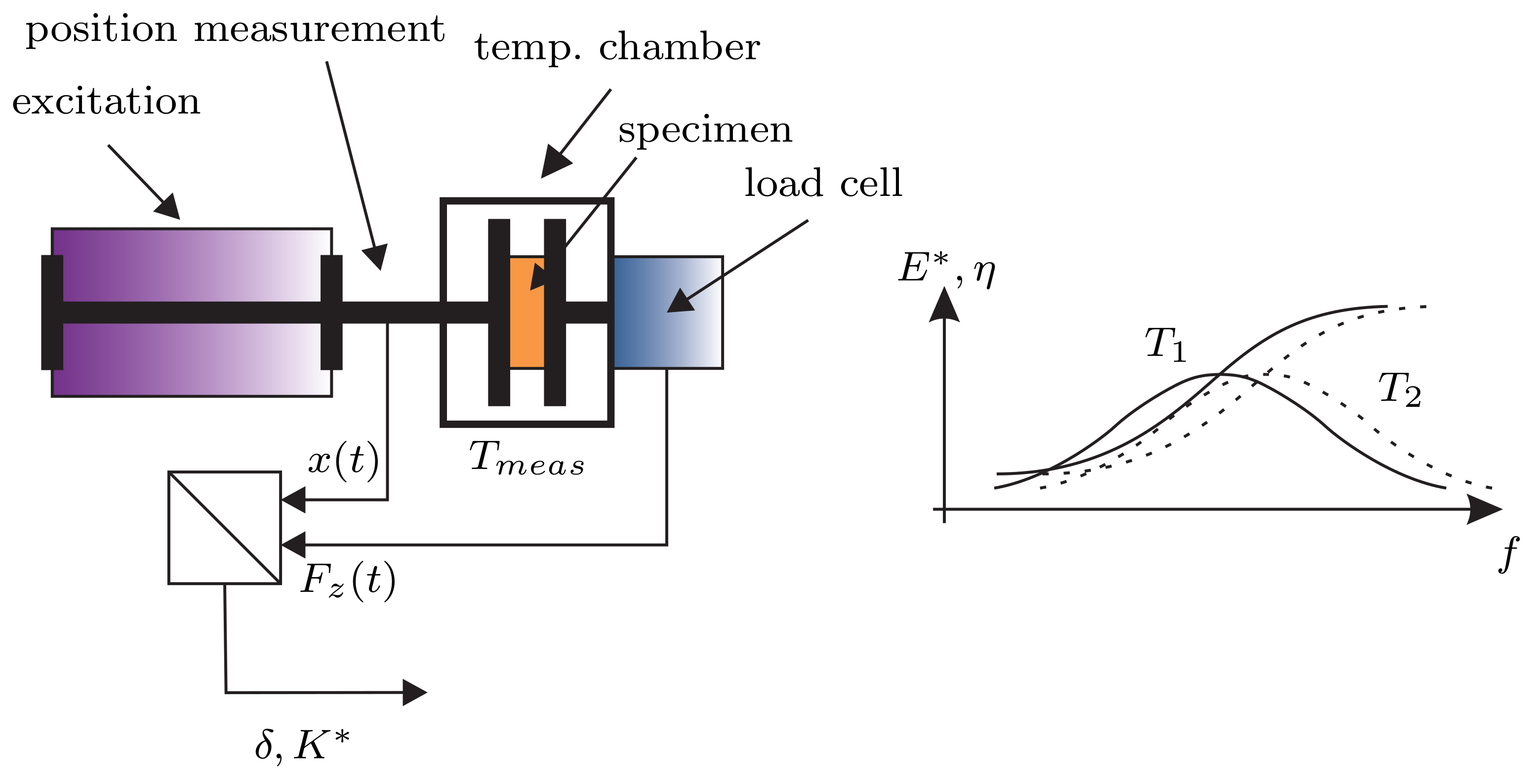
Reliable master curve data is hardly provided by most manufacturers and even if available it is essential to know the exact measurement conditions. For example a measurement under precompression shows a very different behavior compared to the same measurement without precompression. Hence, it was decided to measure the data on our own. Even though the measurement principle looks simple, it is a very tricky task. In Figure 4 the employed measuring method is shown. It is based on the so called Dynamic-Mechanic-Temperature-Analysis (DMTA).

Figure 4.
Scheme of the employed measuring method for the viscoelastic materials.
A specimen is excited at different temperatures by harmonic deformation at various frequencies. In the process the reaction force is measured by a load cell. Thereby, the ratio between force and displacement reflects the stiffness of the material. Due to dissipation effects a phase shift occurs between the force and the displacement, which represents the damping capability of the material. The measurement leads to the so-called isotherms. Thereafter, the measured stiffness values [26] have to be converted to the material significant storage modulus and loss modulus using the geometric parameters of the specimen. For a circular specimen with the height and diameter the relation between the measured axial stiffness and the material modulus E is given by
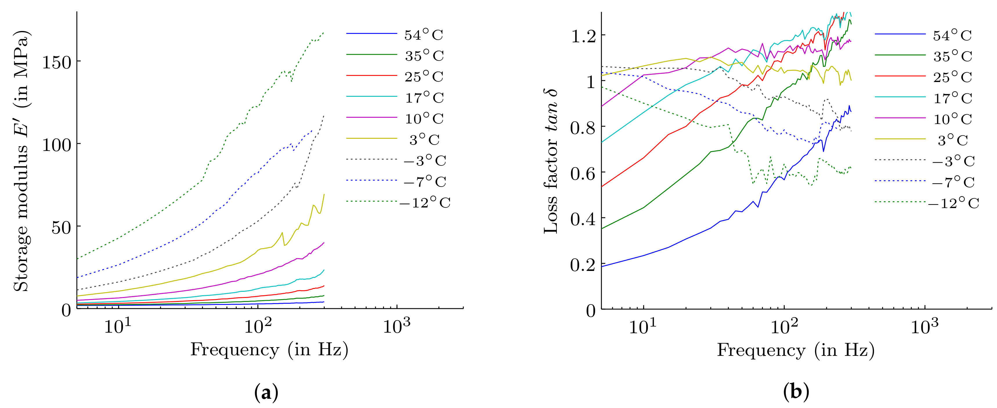
In Figure 5a,b the measured isotherms of a selected butyl rubber with a hardness of Shore A40 are shown. It can be seen that the storage modulus is increasing with lower temperature. However, the loss factor shows, at the beginning, an increase with lower temperature till it reaches a maximum value. Afterwards, the loss factor falls again.
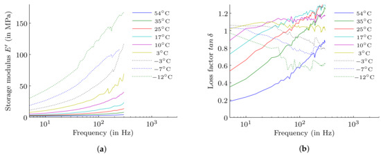
Figure 5.
Storage modulus (a) and loss factor (b) of the measured isotherms.
For this material also measurement data from the manufacturer is available. It was observed that the measured data shows a 50% higher stiffness and a 30% lower loss factor compared to the given data provided by the manufacturer. That proves the difficulty to get proper material specifications. The isotherms are afterwards shifted using Equation (6) processing the vertical shift and (7) for the horizontal shift of the data below the glass transition temperature to obtain the master curve considering a smooth gradient of the stiffness and loss factor. However, there are other possibilities to shift the data. Basically the procedure to find the optimal shift parameters and consequently the identification of the Prony-parameters requires the solution of a nonlinear minimization problem. In this work a genetic algorithm is used varying the shift parameters and determineing the Prony-parameters by minimizing the mean square deviation. The results are plotted in Figure 6. The fitted model shows a very good compliance with the measured data.
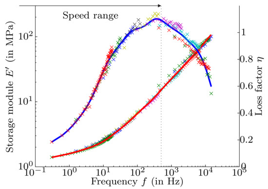
Figure 6.
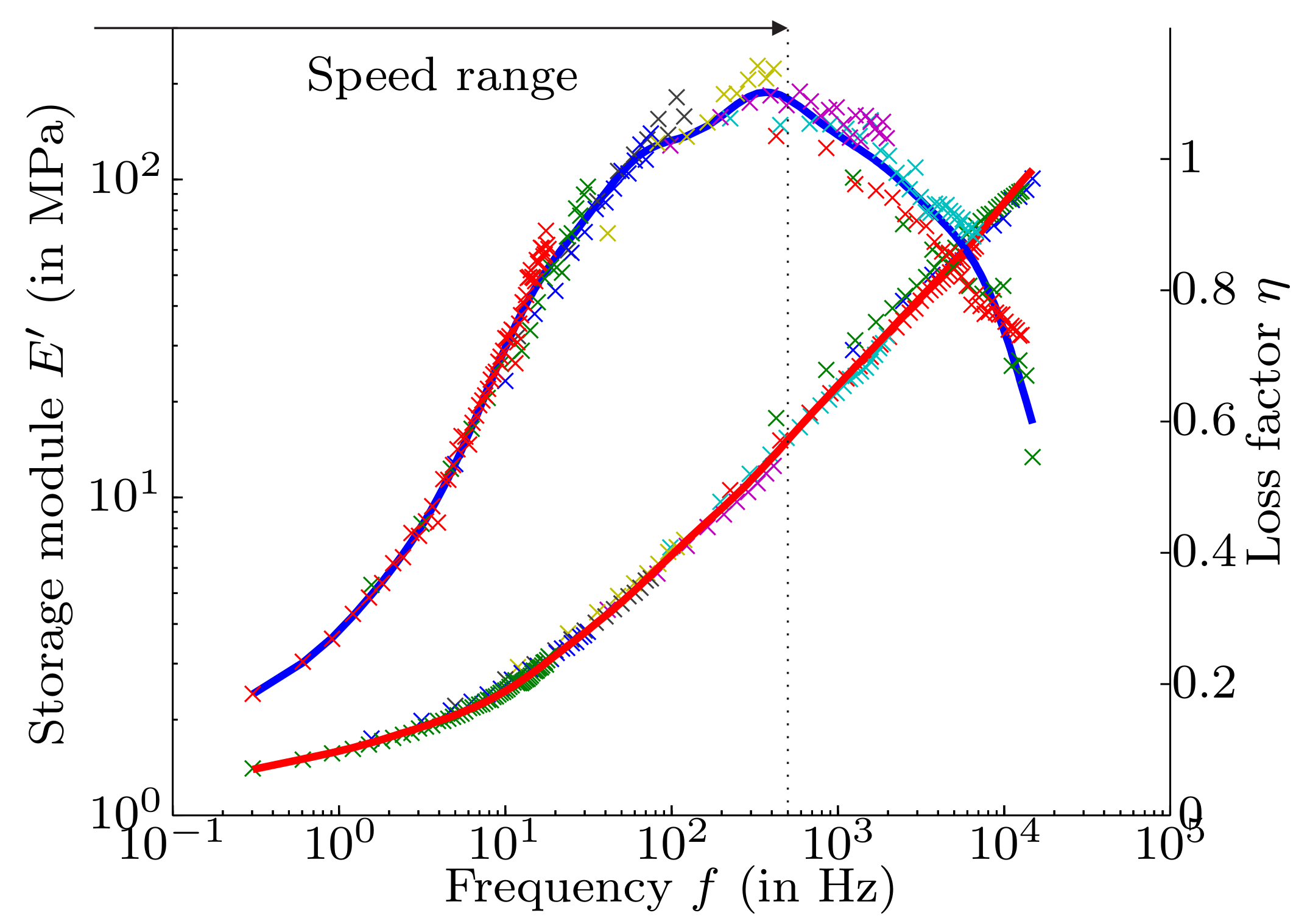
Fitted curves of the storage modulus (red) and the loss factor (blue) in comparison to the measured data (×) at a reference temperature of 25 °C, whereby the different colors mark the various measurement temperatures.
4. Rotordynamic Model
In the considered system, high rotor unbalances are induced by variable process masses acting on the rotor. Obviously, the relative deflection between stator and rotor in the PMB planes are important. To determine the movements of the system bodies the equations of motion have to be derived. Due to the system setup, the AMB, the motor and the upper PMB, are located on a thin shaft. Therefore, also the bending of this part have to be considered. The equations of motion are conducted by using the projection equation [27], which projects the (generalized) forces into the unconstrained space, where the motion takes place. These forces are given by
with and describing the bodies velocities and angular velocities, while and represent the impulse and angular momentum in the reference system R. Thereby,
represent the Jacobian matrices and the therms
are used to consider potential forces (e.g., springs, dampers, elastic potential and gravitation). and describe forces and torque acting on the center of mass.
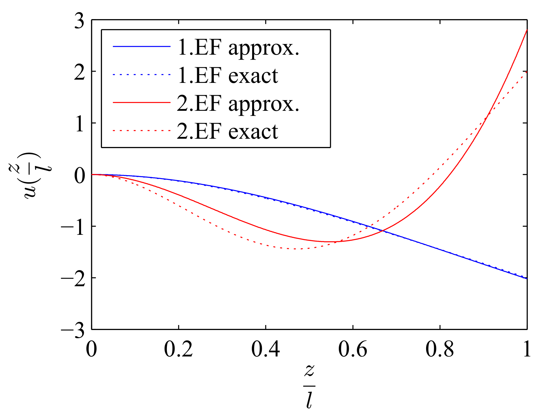
The rotor is modeled as rigid body, whereas the stator is split into a rigid lower part and a flexible upper part, because the moment of resistance of the lower part is much higher due to the increasing diameter. The mass of the AMB and the motor are integrated into the rigid part of the stator to reduce the complexity of the model. The upper PMB is modeled as point mass. As flexible beam model a Ritz approach based on a cubic function is used to describe the occuring displacements of the flexible stator part. Figure 7 shows the comparison of the exact and approximated first and second Eigenmodes of a semibeam. As can be seen, the cubic approach gives a very good representation of the first bending mode which is the most important for the investigated system.
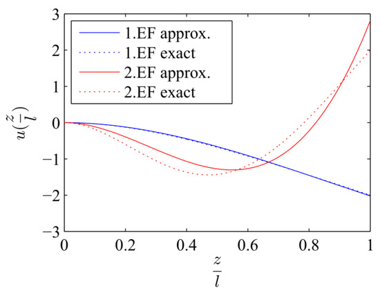
Figure 7.
Comparison of the exact and approximated Eigenmodes of a semibeam bending.
For modelling a linear spring elements the potential energy is used. In the system such linear springs can be used as representation for
- the passive magnetic ring bearings,
- the stiffness of the damping elements,
- the (negative) stiffness of the motor,
- and the (negative) stiffness of the active magnetic bearing in radial direction.
The potential energy of a linear spring is determined by
where describes the relative extension vector of the spring from the force-free position as a function of the generalized coordinates and represents the tensor of spring constants. The same approach can also be used to describe the influence of elastic elements to their attachments. The speed-proportional potential energy of a damper is given by
describes the tensor of damping constants and the relative velocity vector of the damper dependent on and .
The equation of motion obtained from the projection equation generally shows the structure
and is of non-linear character. is the skew symmetric mass matrix. contains the remaining terms of the acceleration like centrifugal- and coriolis forces. In the applied spring-, damper- and weightforces as well as the actuating forces and moments take place. If only small deflections from the rest position are assumed, Equation (14) can be developed by a TAYLOR series. A development up to terms of first order is sufficient and only the linear differential equation for small deflections remains
with
The matrices and can be split in their symmetric and antisymmetric parts whereby the linearized equation of motion is as follows:
- : gyroscopic matrix
- : damping matrix
- : matrix of non-conservative forces
- : matrix of conservative forces (potential forces)
Due to the symmetry of the bearing arrangement, it is possible to halve the system order by introducing complex coordinates. The translations are defined by
and the tilting by
The transformation leads to the system valid in the complex coordinates :
The system matrices are transformed according
whereby stands for a general matrix.
To include the viscoelastic behavior the dynamic system model with states has to be extended with the inner states of the material model
There are the translational and the rotational inner states. The first order differenzial system is then given by
with . This transformation in a first order system is not trivial, because the inner states are massless and thus the mass matrix is not invertible. As the inner states are only present in the first derivative only the general states have to be transformed. The system of the inner states can be included in the last row and column of (23).
With the derived system the deflections of the system as well as the eigenfrequencies can be calculated. For the eigenmodes the linear differential equation
can be solved using an exponential approach
leading to the characteristic system
This system has a non-trivial solution when
The eigenvalues resulting from the solution of the polynomials have thereby the shape
describes the damping constant and the frequency of the corresponding eigenmode. The resulting motions of the system in its eigenmodes are depicted in Figure 8.
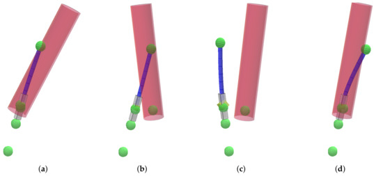
Figure 8.
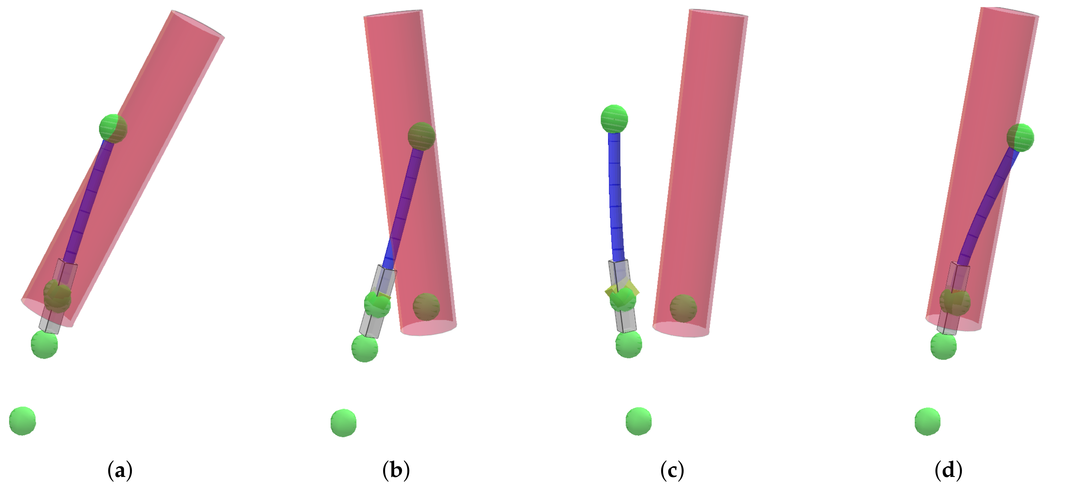
Schematic representation of the system motions in the three rigid body modes (a–c) and the first flexible mode of the stator beam (d).
The green points represent the PMB’s and the viscoelastic damping connections. The red cylinder is thereby showing the rotor and the blue shaft indicates the flexible stator beam connected to the grey rigid part of the stator. As it is shown in the four modes the stator is tilting as a entity, where as the rotor shows a tilting around the lower PMB in the first mode and around the upper PMB in the second mode. In the third rigid mode the rotor points a translational movement. The fourth mode indicates the semibeam bending of the flexible stator beam.
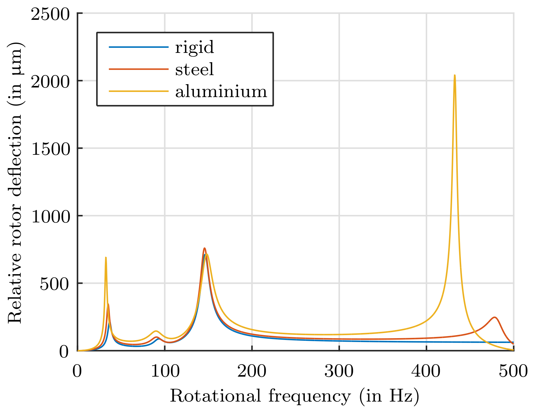
Figure 9 shows the effect of the flexible stator shaft of a designated system for different shaft materials. In the top PMB the deflections in the first resonance at about 40 Hz are increasing with softer material. Furthermore, the bending frequency, which is present in the range of 400–500 Hz is situated in the operation range. The stator shaft material has a huge influence on the relative rotor deflections in the first bending mode. Due to the required space limitation for the AMB, the motor and the position sensor system, the minimum stator shaft length is given with 116 mm as used in Figure 9. As the deflection, due to the bending, cannot be influenced by the stiffness of the PMBs and the stiffness and positioning of the damping elements, the only suitable material for the shaft, that meets the requirements of a maximum deflection in the PMB planes of 500 µm, is steel.

Figure 9.
Relative rotor deflection at the upper PMB of not optimized systems with different shaft materials.
It is our goal to design a system that does not exceed a maximum deflection of 500 µm in both PMBs to prevent contact with the fault bearings in case of a process-unbalance of 20gmm. To achieve this the stiffness and the position of the PMBs and the damping elements are varied for optimization.
5. Optimization
In the first optimization a given system setup was used and only the position and dimensions of the viscoelastic damping elements were optimized by minimizing the relative rotor deflections to the stator in the PMB planes. For optimization the software tool “SymSpace”, developed at the Linz Center of Mechatronics (LCM), was used. It uses a genetic algorithm described in detail in [28]. In Table 1 the main parameters of the system setup are given. The mass of the rotor includes the additional mass which is mounted on the rotor. The variable parameters of the optimization with their referring range limits are shown in Table 2.

Table 1.
Main parameters of the investigated system.
Table 2.
Variables for optimization.
For excitation, two different unbalances with an unbalance value of 20gmm are assumed. They are located at the top and the bottom of the rotors linked part. Finally, it turned out that the employment of two different damping materials leads to the best results. For the bottom viscoelastic element the material with a hardness of Shore A40, which was measured, is preferable. For the upper damping viscoelastic element a softer material with a hardness of Shore A20 shows the best results. However, for this material only the manufacturer data was available leading to an uncertainty since the material parameters play a major role for the rotor dynamic behavior. In Figure 10 the Pareto front of the optimization is shown.
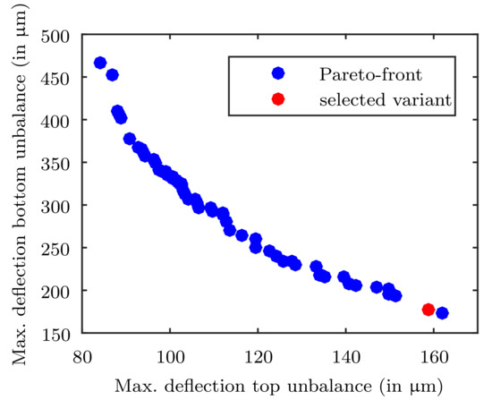
Figure 10.
Pareto-front of the optimization referring the maximum deflections arising due to the specified unbalances of 20 gmm.
It can be seen that the relative rotor deflections can be minimized to a value of 160 µm for both unbalance positions, which is much smaller than the PMB air gap of 500 µm. This proves the high potential of elastomer materials. The optimized values for the damping elements are summarized in Table 3.
Table 3.
Optimized Variables.
Thereby, the lower harder element has the positive effect that it will carry the axial pre-load generated from the system.
6. Verification of the System Model
To verify the system model a prototype was built with the optimized damping elements. To ensure a comparable initial situation to the simulation the rotor was initially balanced without any linked part. As the unbalance of the process mass is not predictable, the verification is done with a system without any process mass. Afterwards, two defined unbalances given in Table 4 were placed at two specified positions also used for the balancing of the system. As it is not easily possible to measure the relative deflections directly, only the absolute rotor movement is compared. The measurements are conducted using laser triangulation sensors with a sample time up to 100 kHz and a resolution of 25nm. Hence, also high rotational speeds can be quantified with high resolution.
Table 4.
Verification unbalances.
To eliminate the effects of the remaining rotor unbalance, the deflections of the balanced rotor were subtracted from the deflections with the defined unbalances. It should be noted that this subtraction has to be performed properly considering the phases of the measured data and is only permitted assuming a linear behavior of the system, which is already assumed in the modeling.
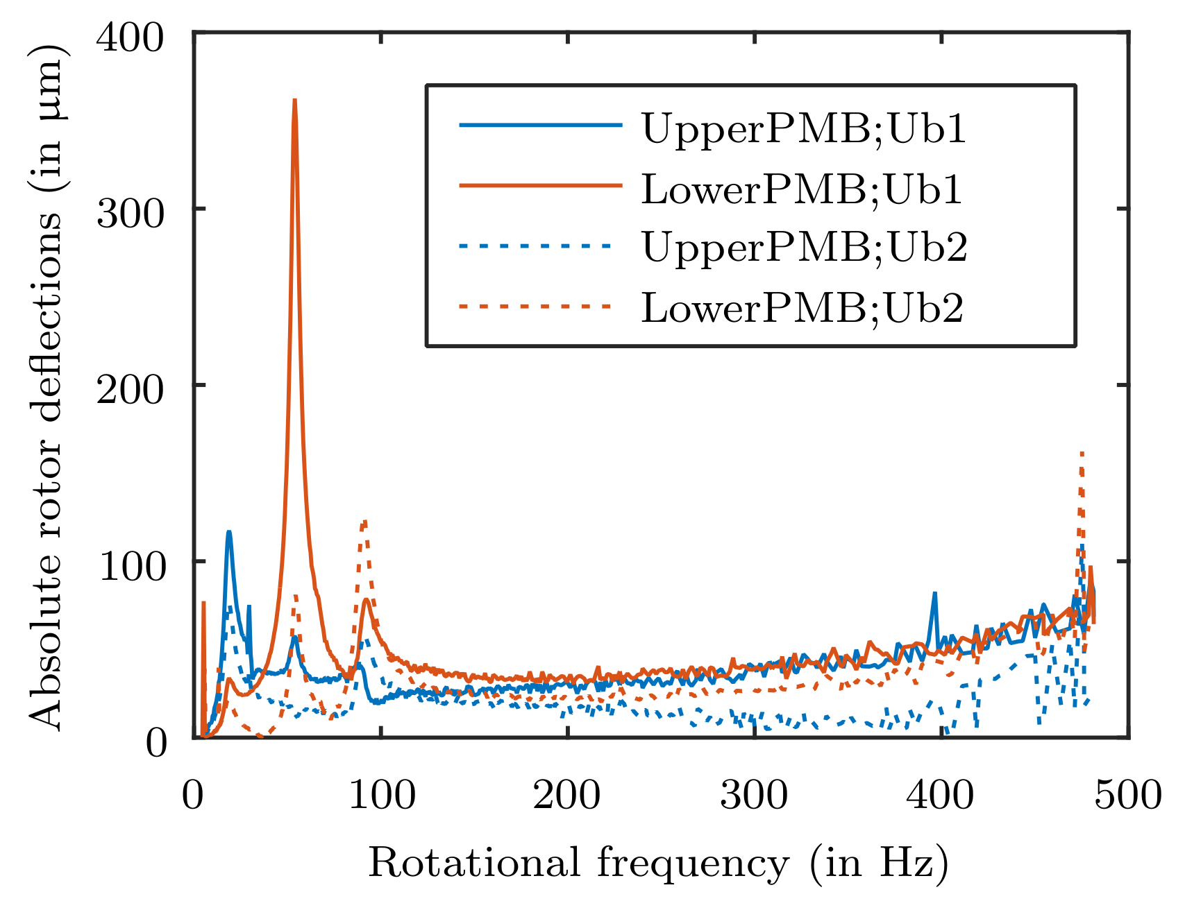
In Figure 11 the measured absolute rotor deflections in the PMB planes (see Figure 1) over to the rotational rotor frequency is shown. It can be noticed that the highest displacement is occuring in the lower PMB due to the unbalance in the upper balance plane. The difference to the low optimized deflections shown in Figure 10 is caused by the lower rotor mass of the verification system as it is measured without the additional mass, which has an negative influence on the system adjustment as shown in [20].
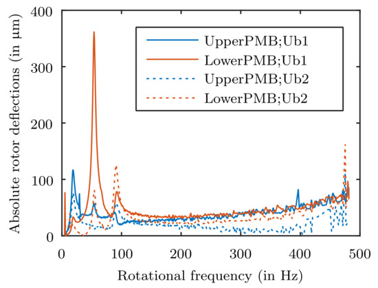
Figure 11.
Measured deflections of the system according to applied unbalances as given in Table 4.
Thus, the measured rotor displacements need to be compared with an adapted simulation. For this the rotor has to be modified to characterize the one in the measured system without the process mass. Without the process mass the rotor features the data given in Table 5.
Table 5.
Parameters of the varified rotor.
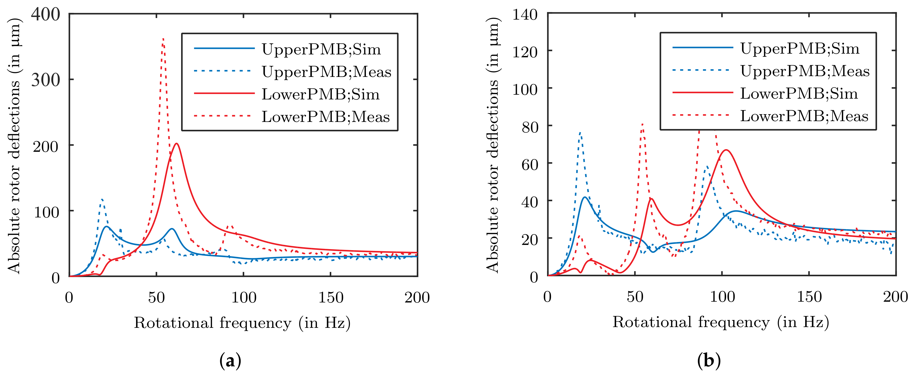
Comparing the adapted simulation with the measurement, as shown in Figure 12, revealed that the rigid body modes of the real system are situated at lower frequencies. That indicates a system featuring a lower overall stiffness. To identify the source of the difference first the stiffness of the PMBs are investigated. In a separated measurement of the PMBs it turned out, that the real stiffness is 20% lower than calculated. This is due to a lower PM remanent flux density, which was also confirmed with a dipole measurement of the PM rings.
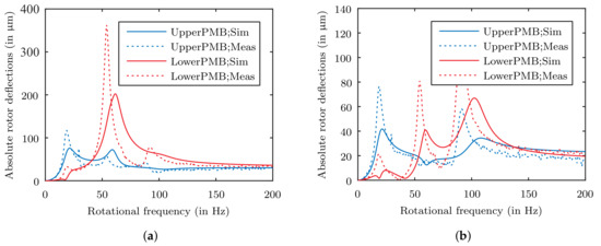
Figure 12.
Comparison of the measured data with the simulated deflections with “Unbalance1” (a) and “Unbalance2” (b) specified in Table 4.
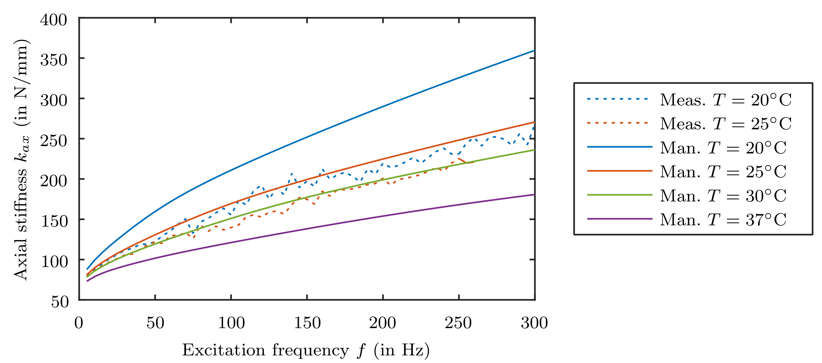
Furthermore, the difference in the Eigenfrequencies indicate that the material of the upper damping element offers a lower stiffness, either. To verify this assumption measurements of the used material with a hardness of Shore A20 at a temperature of 20 °C and 25 °C were performed and compared to the related stiffness and damping factor characteristics provided by the manufacturer.
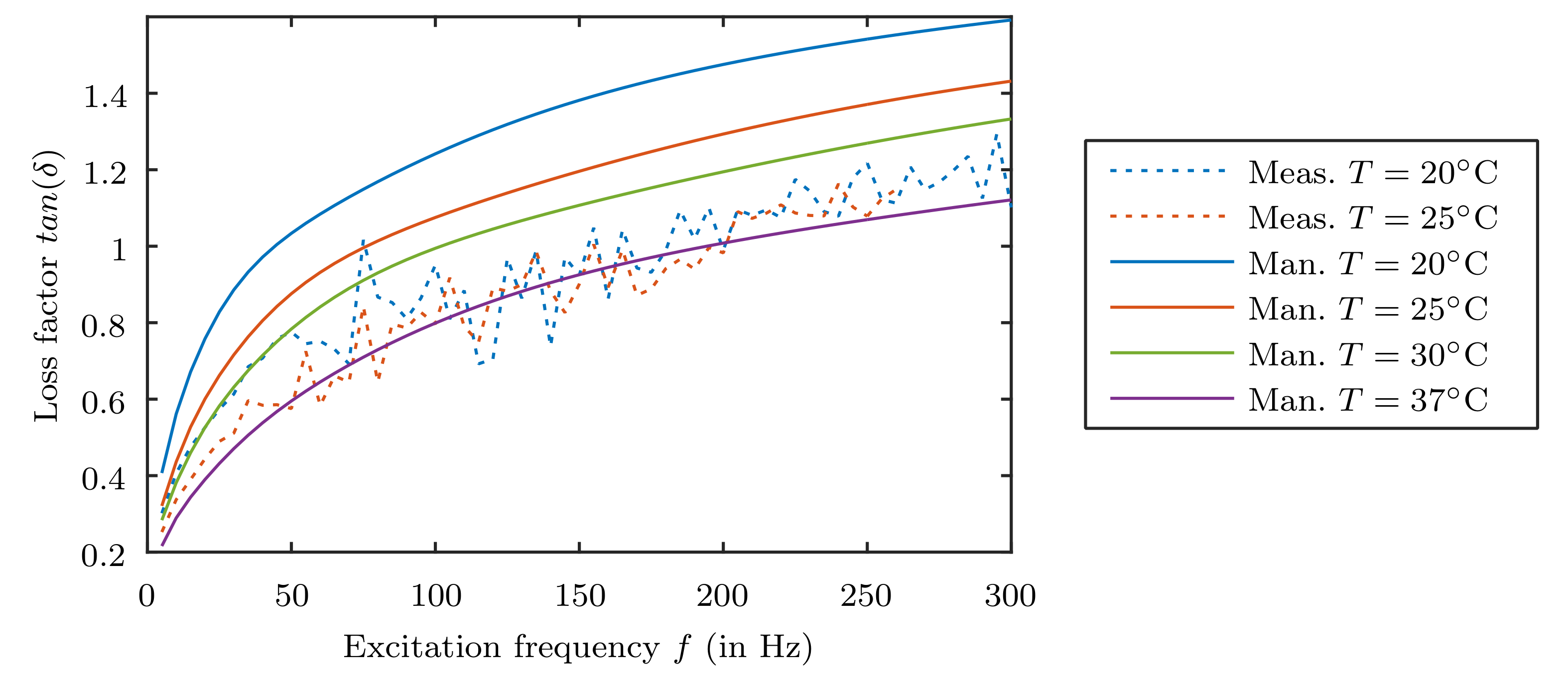
Figure 13 and Figure 14 show that the real stiffness and damping behavior is smaller than expected. The measured stiffness values is only be reflected when setting the manufacturer data to a 5 °C higher temperature. Regarding the loss factor of the material even about 12 °C temperature rise has to be performed. That result shows again the necessity for proper material data, since the damping directly affects the occurring deflections of the rotor. The large deviation is also due to the measuring method used by the manufacturer, which uses a prestressing of the material in comparison to the self-used measurement process without prestressing.
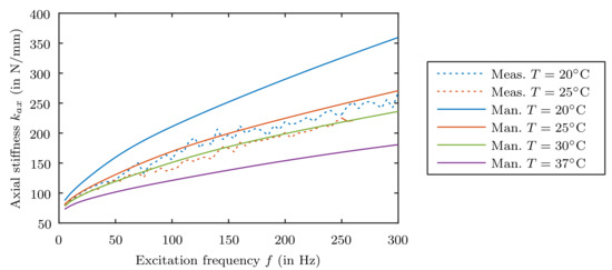
Figure 13.
Comparison of measured probe stiffness with the manufacturer data.
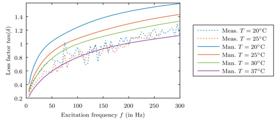
Figure 14.
Comparison of measured loss factor with the manufacturer data.
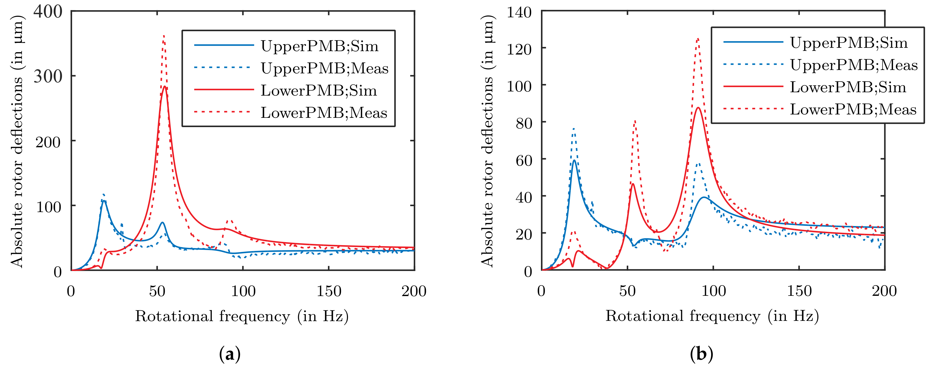
In Figure 15 the comparison of the adjusted simulation is presented. The adopted temperature was set to a 12 °C higher temperature as the loss factor is the most important parameter considering the deflection amplitudes. The frequency range is limited to 200 Hz since the bending of the stator shaft is hardly apparent. The deflections show a very good agreement with the measurements.
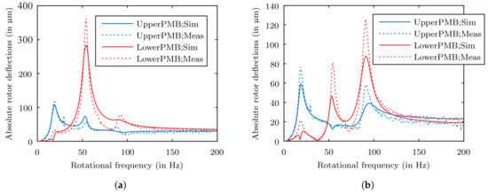
Figure 15.
Comparison of the measured data with the simulated deflections with “Unbalance1” (a) and “Unbalance2” (b) specified in Table 4 considering the lower PMB stiffnesses and a adopted temperature of 37 °C for the upper damping element.
7. Discussion
Bringing magnetic bearing technology to a broader field of application requires the reduction of complexity and costs. The idea to use passive magnetic bearings, to achieve this goal, seems promising. So in the best case only one degree of freedom has to be controlled actively what saves costs for required actors, sensors and power electronics. Moreover, passive permanent magnetic bearings feature high reliability in case of power loss and failures. Disadvantageous proves the fact, that these type of bearings require a precise design regarding their field of application. Based on the nearly undamped system behavior, unbalances play a critical role. Different to active magnetic bearings no damping can be induced and adjusted by control, which is one of the main reasons for the limited use in commercial products. However, there are many ways to induce damping into such systems. To keep the cost advantage of passive magnetic bearings, a solution for damping must be found which only causes low additional costs. Using viscoelastic damping elements often failed in the past due to the very complex modeling and the hardly available and reliable manufacturers data. Even if available, the data is strongly influenced by the measurement process. As shown in this work, useful results can only be obtained when the exact characteristics of the damping material is well known. Unfortunately its determination is very time-consuming and an expensive task.
Moreover, a proper model of the rotordynamic behavior has to be derived to evaluate the occurring deflections of the system parts. Thereby, the most important deflections, which has to be considered, are the relative deflections in the PMB’s. Since the air gap between the outer rings and the inner rings is limited, it has to be ensured, that any contact is prohibited. Thus, the generation of a proper all-over system model is complex. As there are numerous parameters influencing the system performance, the demand for an optimization is obvious. As is shown, the right configuration leads to very good results according the stabilizability of unbalances. However, only the knowledge of the exact system parameters guarantee a proper prediction of the dependent variables.
Author Contributions
Conceptualization, J.P.; validation, J.P.; formal analysis, J.P.; investigation, J.P.; writing—original draft preparation, J.P.; measurements, J.P.; writing—review and editing, G.J.; supervision, G.J.; funding acquisition, W.A.
Funding
This research received no external funding.
Acknowledgments
The presented research work has been supported by the Linz Center of Mechatronics GmbH (LCM), which is part of the COMET/K2 program of the Federal Ministry of Transport, Innovation and Technology and the Federal Ministry of Economics and Labor of Austria. The authors would like to thank the Austrian and Upper Austrian Government for their support.
Conflicts of Interest
The authors declare no conflict of interest.
References
- Kailasan, A.; Dimond, T.; Allaire, P.; Sheffler, D. Design and Analysis of a Unique Energy Storage Flywheel System—An Integrated Flywheel, Motor/Generator, and Magnetic Bearing Configuration. J. Eng. Gas Turbines Power 2015, 137, 042505. [Google Scholar] [CrossRef]
- Circosta, S.; Bonfitto, A.; Lusty, C.; Keogh, P.; Amati, N.; Tonoli, A. Analysis of a Shaftless Semi-Hard Magnetic Material Flywheel on Radial Hysteresis Self-Bearing Drives. Actuators 2018, 7, 87. [Google Scholar] [CrossRef]
- Jungmayr, G.; Amrhein, W.; Grabner, H. Minimization of forced vibrations of a magnetically levitated shaft due to magnetization toleranzes. In Proceedings of the 12th International Symposium on Transport Phenomena and Dynamic of Rotating Machinery, Honolulu, HI, USA, 17–22 February 2008. [Google Scholar]
- Delamare, J.; Yonnet, J.P.; Rulliere, E. A Compact Magnetic Suspension With Only One Axis Control. IEEE Trans. Magn. 1994, 30, 4746–4748. [Google Scholar] [CrossRef]
- Lodge, W.S. The Passive Characteristics of Repulsion Magnetic Bearing; Techreport 76170; Royal Aircraft Establishment: Farnborough, UK, 1976. [Google Scholar]
- Yonnet, J.P. Permanent Magnet Bearings and Couplings. IEEE Trans. Magn. 1981, 17, 1169–1173. [Google Scholar] [CrossRef]
- Yonnet, J.P. Etude des Paliers Magnetiques Passives. Ph.D. Thesis, Universite de Grenoble, Saint-Martin-d’Hères, France, 1980. [Google Scholar]
- Marinescu, M. Analytische Berechnung und Modellvorstellungen für Systeme mit Dauermagneten und Eisen. Ph.D. Thesis, TU Braunschweig, Braunschweig, Germany, 1979. [Google Scholar]
- Lang, H. Fast calculation method of forces and stiffnesses of permanent-magnet bearing. In Proceedings of the 8th International Symposium on Magnetic Bearings, Mito, Japan, 26–28 August 2002. [Google Scholar]
- Jungmayr, G. Der Magnetisch Gelagerte Lüfter. Ph.D. Thesis, Johannes Kepler University, Linz, Austria, 2008. [Google Scholar]
- Chen, H.; Walter, T.; Wheeler, S.; Lee, N. A Passive Magnet Bearing System for Energy Storage Flywheels. In Proceedings of the 9th International Symposium on Magnetic Bearings, Lexington, Kentucky, 3–6 August 2004. [Google Scholar]
- Filatov, A.V.; Hawkins, L.A.; Krishnan, V.; Law, B. Active Axial Electromagnetic Damper. In Proceedings of the 11th International Symposium on Magnetic Bearings, Nara, Japan, 26–29 August 2008. [Google Scholar]
- Filatov, A.; Maslen, E.H. Passive Magnetic Bearing for Flywheel Energy Storage System. IEEE Trans. Magn. 2001, 37, 3913–3924. [Google Scholar] [CrossRef]
- Beams, J.W. Double Magnetic Suspension. Rev. Sci. Instrum. 1963, 34, 1071–1074. [Google Scholar] [CrossRef]
- Moser, R.; Sandtner, J.; Bleuler, H. Optimization of Repulsive Passive Bearings. IEEE Trans. Magn. 2006, 42, 2038–2042. [Google Scholar] [CrossRef]
- Earnshaw, S. On the Nature of Molecular Forces which regulate the Constitution of the Luminiferous Ether. Trans. Camb. Philos. Soc. 1842, 7, 97–112. [Google Scholar]
- Braunbeck, W. Freischwebende Körper im elektrischen und magnetischem Feld. Z. Phys. 1939, 112, 753–763. [Google Scholar] [CrossRef]
- Passenbrunner, J.; Jungmayr, G.; Panholzer, M.; Silber, S.; Amrhein, W. Simulation and Optimization of an Eddy Current Position Sensor. In Proceedings of the 11th IEEE International Conference on Power Electronics and Drive Systems (PEDS 2015), Sydney, Australia, 9–12 June 2015. [Google Scholar]
- Passenbrunner, J.; Silber, S.; Amrhein, W. Investigation of a Digital Eddy Current Sensor. In Proceedings of the IEEE International Electric Machines and Drives Conference ( IEMDC), Coeur d’Alène, ID, USA, 10–13 May 2015. [Google Scholar]
- Marth, E.; Jungmayr, G.; Amrhein, W. Fundamental Considerations on Introducing Damping to Passively Magnetically Stabilized Rotor Systems. Adv. Mech. Eng. 2016, 8. [Google Scholar] [CrossRef]
- Bormann, A. Elastomerringe zur Schwingungsberuhigung in der Rotordynamik—Theorie, Messungen und optimierte Auslegung. Ph.D. Thesis, Technische Universität Berlin, Berlin, Germany, 2005. [Google Scholar]
- Osswald, T. Understanding Polymer Processing; Hanser: München, Germany, 2010. [Google Scholar]
- Bonfitto, A.; Tonoli, A.; Amati, N. Viscoelastic Dampers for Rotors: Modeling and Validation at Component and System Level. Appl. Sci. 2017, 7, 1181. [Google Scholar] [CrossRef]
- Gutierrez-Lemini, D. Engineering Viscoelasticity; Springer: Berlin, Germany, 2014. [Google Scholar]
- Ecker, R. Der Einfluss verstaerkender Russe auf die viskoelastischen Eigenschaften von amorphen Elastomeren. Kautsch. Gummi Kunstst. 1968, 21, 304–317. [Google Scholar]
- Ferry, J.D. Viscoelastic Properties of Polymers, 3rd ed.; John Wiley & Sons Ltd.: New York, NY, USA, 1970. [Google Scholar]
- Bremer, H. Elastic Multibody Dynamics; Springer: Berlin, Germany, 2008. [Google Scholar]
- Silber, S.; Koppelstätter, W.; Weidenholzer, G.; Bramerdorfer, G. MagOpt—Optimization Tool for Mechatronic Components. In Proceedings of the ISMB14, 14th International Symposium on Magnetic Bearings, Linz, Austria, 11–14 August 2014; pp. 243–246. [Google Scholar]

© 2019 by the authors. Licensee MDPI, Basel, Switzerland. This article is an open access article distributed under the terms and conditions of the Creative Commons Attribution (CC BY) license (http://creativecommons.org/licenses/by/4.0/).