Force-Amplified Soft Electromagnetic Actuators

Abstract
:1. Introduction
2. Materials and Methods
2.1. Fabrication
2.2. Design
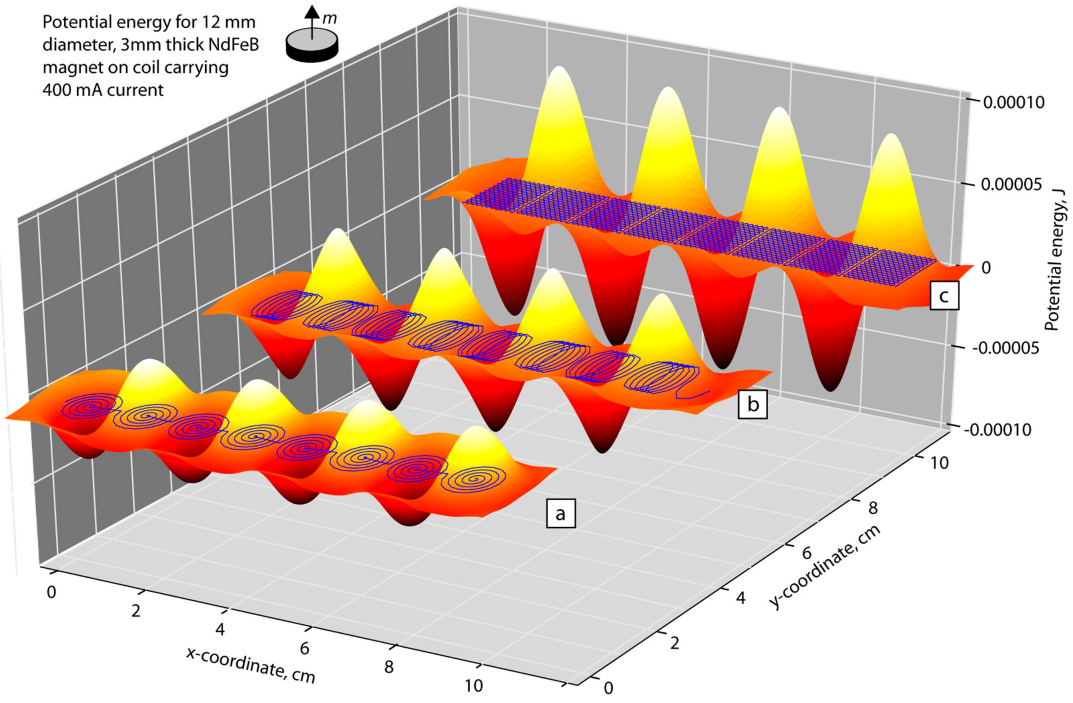
2.3. Electromagnetic Modeling
2.4. Driving Circuit
2.5. Force Measurements
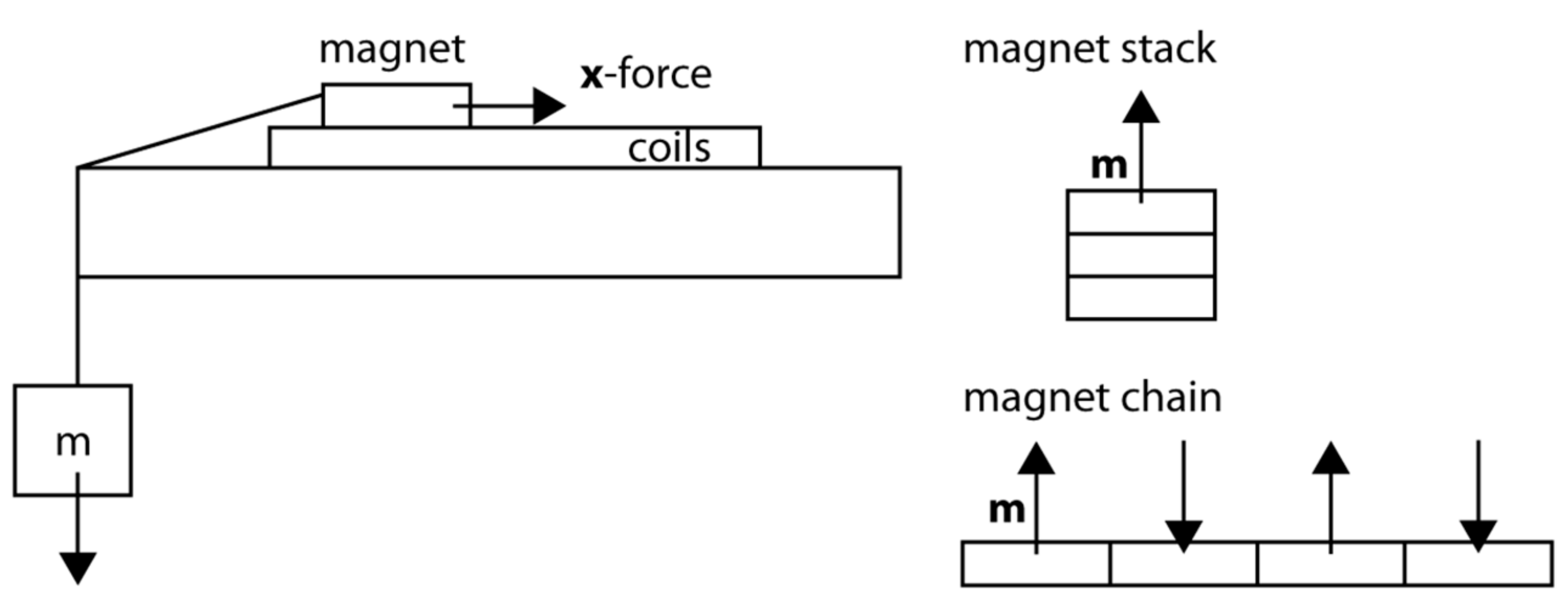
2.6. Mechanical Amplification
3. Results
3.1. Force Measurements
3.2. Force Amplification
4. Discussion
Supplementary Materials
Author Contributions
Funding
Acknowledgments
Conflicts of Interest
References
- Christianson, C.; Goldberg, N.N.; Deheyn, D.D.; Cai, S.; Tolley, M.T. Translucent soft robots driven by frameless fluid electrode dielectric elastomer actuators. Sci. Robot. 2018, 3, eaat1893. [Google Scholar] [CrossRef]
- Shepherd, R.F.; Stokes, A.A.; Freake, J.; Barber, J.; Snyder, P.W.; Mazzeo, A.D.; Cademartiri, L.; Morin, S.A.; Whitesides, G.M. Using explosions to power a soft robot. Angew. Chem. Int. Ed. 2013, 52, 2892–2896. [Google Scholar] [CrossRef] [PubMed]
- Lee, S.; Karavas, N.; Quinlivan, B.T.; Ryan, D.L.; Perry, D.; Eckert-Erdheim, A.; Murphy, P.; Goldy, T.G.; Menard, N.; Athanassiu, M.; et al. Autonomous Multi-Joint Soft Exosuit for Assistance with Walking Overground. In Proceedings of the 2018 IEEE International Conference on Robotics and Automation (ICRA), Brisbane, Australia, 21–25 May 2018. [Google Scholar]
- Brown, E.; Rodenberg, N.; Amend, J.; Mozeika, A.; Steltz, E.; Zakin, M.R.; Lipson, H.; Jaeger, H.M. Universal robotic gripper based on the jamming of granular material. Proc. Natl. Acad. Sci. USA 2010, 107, 18809–18814. [Google Scholar] [CrossRef] [Green Version]
- Carrozza, M.C.; Suppo, C.; Sebastiani, F.; Massa, B.; Vecchi, F.; Lazzarini, R.; Cutkosky, M.R.; Dario, P. The SPRING hand: Development of a self-adaptive prosthesis for restoring natural grasping. Auton. Robots 2004, 16, 125–141. [Google Scholar] [CrossRef]
- Haines, C.S.; Lima, M.D.; Li, N.; Spinks, G.M.; Foroughi, J.; Madden, J.D.; Kim, S.H.; Fang, S.; de Andrade, M.J.; Göktepe, F.; Göktepe, Ö. Artificial muscles from fishing line and sewing thread. Science 2014, 343, 868–872. [Google Scholar] [CrossRef] [PubMed]
- Yip, M.C.; Niemeyer, G. High-performance robotic muscles from conductive nylon sewing thread. In Proceedings of the 2015 IEEE International Conference on Robotics and Automation (ICRA), Seattle, WA, USA, 20–30 May 2015; pp. 2313–2318. [Google Scholar]
- He, Q.; Wang, Z.; Song, Z.; Cai, S. Bioinspired Design of Vascular Artificial Muscle. Adv. Mater. Technol. 2018, 1800244. [Google Scholar] [CrossRef]
- Chenal, T.P.; Case, J.C.; Paik, J.; Kramer, R.K. Variable stiffness fabrics with embedded shape memory materials for wearable applications. In Proceedings of the 2014 IEEE/RSJ International Conference on Intelligent Robots and Systems (IROS 2014), Chicago, IL, USA, 14–18 September 2014; pp. 2827–2831. [Google Scholar]
- Salerno, M.; Firouzeh, A.; Paik, J. A low profile electromagnetic actuator design and model for an origami parallel platform. J. Mech. Robot. 2017, 9, 041005. [Google Scholar] [CrossRef]
- Yamahata, C.; Lotto, C.; Al-Assaf, E.; Gijs, M.A.M. A PMMA valveless micropump using electromagnetic actuation. Microfluid. Nanofluid. 2005, 1, 197–207. [Google Scholar] [CrossRef]
- Do, T.N.; Phan, H.; Nguyen, T.Q.; Visell, Y. Miniature Soft Electromagnetic Actuators for Robotic Applications. Adv. Funct. Mater. 2018, 28, 1800244. [Google Scholar] [CrossRef]
- Ebrahimi, N.; Nugroho, S.; Taha, A.F.; Gatsis, N.; Gao, W.; Jafari, A. Dynamic Actuator Selection and Robust State-Feedback Control of Networked Soft Actuators. arXiv, 2018; arXiv:1804.01615. [Google Scholar]
- Nemitz, M.P.; Mihaylov, P.; Barraclough, T.W.; Ross, D.; Stokes, A.A. Using voice coils to actuate modular soft robots: Wormbot, an example. Soft Robot. 2016, 3, 198–204. [Google Scholar] [CrossRef] [PubMed]
- Guo, R.; Sheng, L.; Gong, H.; Liu, J. Liquid metal spiral coil enabled soft electromagnetic actuator. Sci. China Technol. Sci. 2018, 61, 516–521. [Google Scholar] [CrossRef]
- Mercorelli, P.; Lehmann, K.; Liu, S. Robust Flatness Based Control of an Electromagnetic Linear Actuator Using Adaptive PID Controller. In Proceedings of the 42nd IEEE Conference on Decision and Control, Maui, HI, USA, 9–12 December 2003. [Google Scholar]
- Chen, L.; Mercorelli, P.; Liu, S. A Kalman estimator for detecting repetitive disturbances. In Proceedings of the 2005 American Control Conference, Portland, OR, USA, 8–10 June 2005; pp. 1631–1636. [Google Scholar]
- Flip-Dot Actuator on Fabric. Available online: https://www.kobakant.at/DIY/?p=5915 (accessed on 28 September 2018).
- Soft Speaker on Fabric. Available online: https://blog.adafruit.com/2015/04/01/machine-embroidered-speaker-wearablewednesday/ (accessed on 28 September 2018).
- Kimmer, C.J.; Harnett, C.K. Combining Strings and Fibers with Additive Manufacturing Designs. In Proceedings of the ASME 2016 International Design Engineering Technical Conferences and Computers and Information in Engineering Conference, Charlotte, NC, USA, 21–24 August 2016; p. V004T05A014. [Google Scholar]
- Harnett, C.K.; Zhao, H.; Shepherd, R.F. Stretchable Optical Fibers: Threads for Strain-Sensitive Textiles. Adv. Mater. Technol. 2017, 2, 1700087. [Google Scholar] [CrossRef]
- Ceron, S.; Cohen, I.; Shepherd, R.; Pikul, J.; Harnett, C. Fiber Embroidery of Self-Sensing Soft Actuators. Biomimetics 2018, 3, 24. [Google Scholar] [CrossRef]
- Kiourti, A.; Lee, C.; Volakis, J.L. Fabrication of textile antennas and circuits with 0.1 mm precision. IEEE Antennas Wirel. Propag. Lett. 2016, 15, 151–153. [Google Scholar] [CrossRef]
- Rahimi, R.; Ochoa, M.; Yu, W.; Ziaie, B. A sewing-enabled stitch-and-transfer method for robust, ultra-stretchable, conductive interconnects. J. Micromech. Microeng. 2014, 24, 095018. [Google Scholar] [CrossRef]
- Python Notebook for Plotting Square Coils. Available online: https://github.com/harnettlab/iPythonNotebookRepo/blob/master/FiberDrive/SquareCoil.ipynb (accessed on 23 September 2018).
- PESWrite Code for Making PES Embroidery Files from Coordinates. Available online: https://github.com/harnettlab/iPythonNotebookRepo/blob/master/PESWrite2.ipynb (accessed on 23 September 2018).
- Python Notebook for Force Simulation, and Three Example Coil Patterns. Available online: https://github.com/harnettlab/iPythonNotebookRepo/tree/master/FiberDrive (accessed on 23 September 2018).
- Friction Coefficient Table. Available online: http://www.engineershandbook.com/Tables/frictioncoefficients.htm (accessed on 28 September 2018).
- Harnett, C.K.; Wagner, B.P. Expanding the Robotics Materials Set with Machine Embroidery. In Proceedings of the Material Robotics—Bridging Materials Science and Robotics Workshop at the Robotics: Science and Systems (RSS), Cambridge, MA, USA, 15 July 2017. [Google Scholar]
- Harnett, C.K.; Wagner, B.P. Integrating Fibers in Robotics Using Automation. Module of Online Soft Robotics Toolkit. Available online: https://softroboticstoolkit.com/integrating-fibers (accessed on 23 September 2018).


| Design | Wire Length Per Coil (cm) | Maximum Force Exerted (mN) |
|---|---|---|
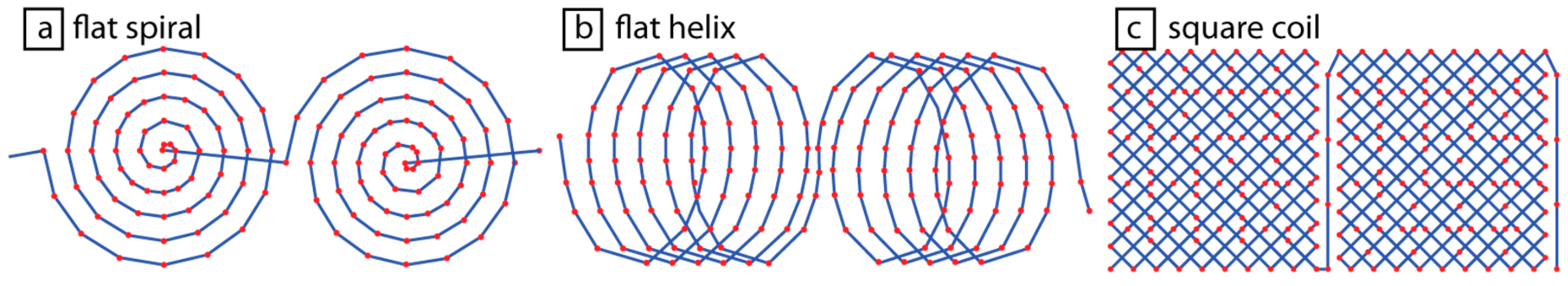
| Flat spirals (Figure 2a) | 10.2 | 9.8 |
| Flat helix (Figure 2b) | 16.9 | 17.0 |
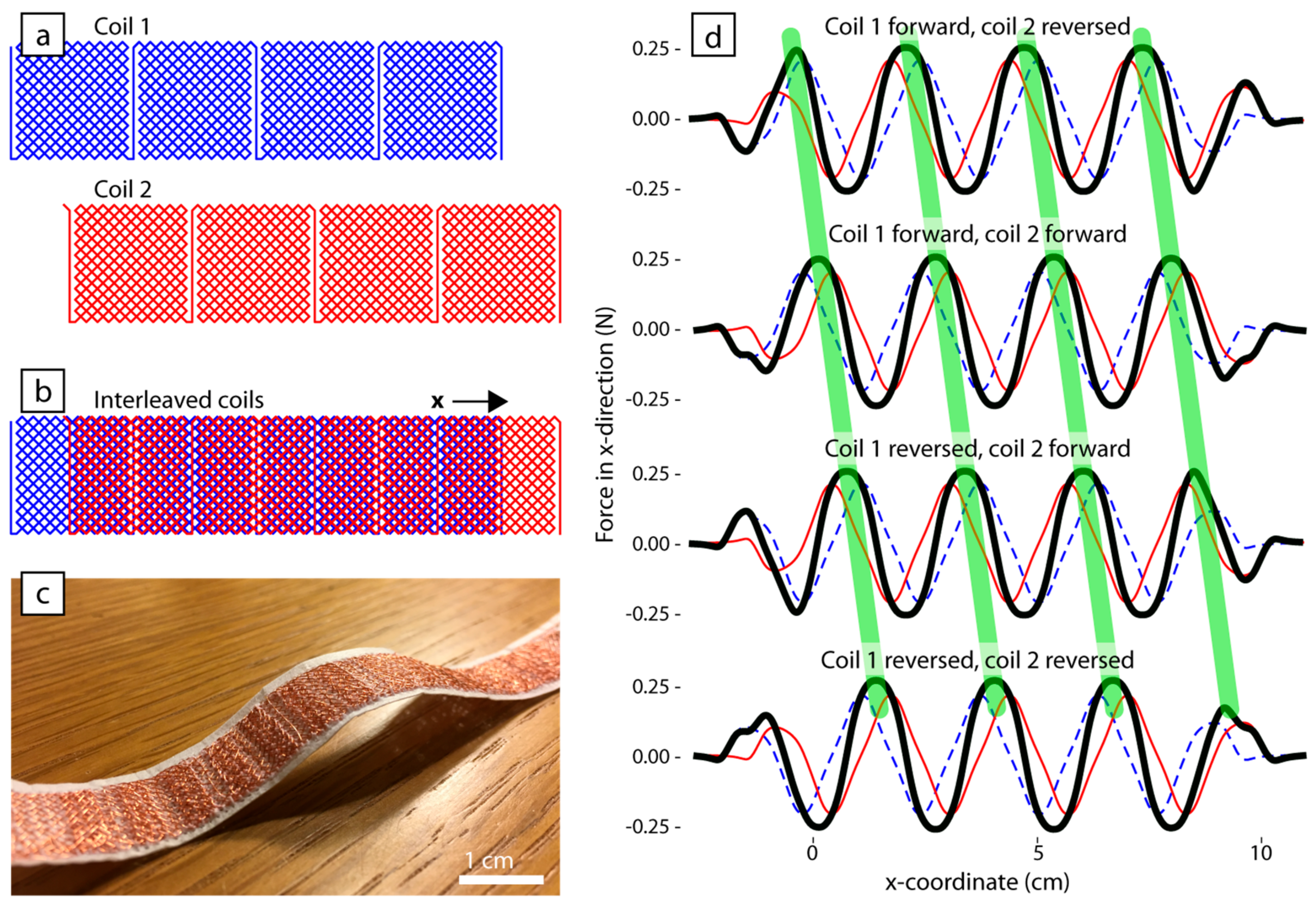
| Square coils (Figure 2c) | 37.0 | 26.5 |
| Number of Sliders in the Amplifier | Maximum Mass Lifted (g) | Corresponding Force (mN) |
|---|---|---|
| 0 (Direct drive) | 0.37 | 3.7 |
| 1 | 0.74 | 7.3 |
| 2 | 1.49 | 14.7 |
© 2018 by the authors. Licensee MDPI, Basel, Switzerland. This article is an open access article distributed under the terms and conditions of the Creative Commons Attribution (CC BY) license (http://creativecommons.org/licenses/by/4.0/).
Share and Cite
Doerger, S.R.; Harnett, C.K. Force-Amplified Soft Electromagnetic Actuators. Actuators 2018, 7, 76. https://doi.org/10.3390/act7040076
Doerger SR, Harnett CK. Force-Amplified Soft Electromagnetic Actuators. Actuators. 2018; 7(4):76. https://doi.org/10.3390/act7040076
Chicago/Turabian StyleDoerger, Stanley R., and Cindy K. Harnett. 2018. "Force-Amplified Soft Electromagnetic Actuators" Actuators 7, no. 4: 76. https://doi.org/10.3390/act7040076
APA StyleDoerger, S. R., & Harnett, C. K. (2018). Force-Amplified Soft Electromagnetic Actuators. Actuators, 7(4), 76. https://doi.org/10.3390/act7040076