Article

Effects of Off-Plane Deformation and Biased Bi-Axial Pre-Strains on a Planar Contractile Dielectric Elastomer Actuator

Department of Mechanical Engineering, University of Bath, Bath BA27AY, UK
*
Author to whom correspondence should be addressed.
Actuators 2018, 7(4), 75; https://doi.org/10.3390/act7040075
Submission received: 26 September 2018 / Revised: 24 October 2018 / Accepted: 27 October 2018 / Published: 30 October 2018

Abstract

:
Dielectric elastomers are in a special class of electro-active polymers known for generating expansion in plane and contraction in thickness under voltage application. This paper advances the understanding of a planar contractile dielectric elastomer actuator (cDEA) that is distinct from conventional multi-layer cDEAs but generates comparable contractile strains. Its structure has a rod-constrained rhombus-shaped electrode region, which undergoes simultaneous in-plane contraction and extension during actuation depending on the configuration of the rod-constraining. It is demonstrated that when the planar cDEA is driven by high voltages, off-plane deformation (i.e., wrinkling) in the direction of contraction causes the rod-constrained electrode region to lose tension and extend in the lateral direction, resulting in a significant increase in contraction strain. It also demonstrates that the contraction strain can be increased further by having biased bi-axial pre-strains. By incorporating both effects, the new cDEA generates a maximum contraction strain of 13%, twice that reported previously for planar cDEAs. A modified planar cDEA, having an additional rigid frame to maintain the pre-strain in the lateral direction to contraction was also developed to demonstrate contractile force actuation. Finally, a stability study shows that the planar cDEA has a primary failure mode of electrical breakdown close to the corners of the rod-constrained electrode region. Having inactive regions around the active cell is essential for generating contraction and eliminating buckling of the planar cDEA in the lateral direction.

1. Introduction

Dielectric Elastomers (DEs) are known for their significant potential in performing muscle-like actuation. A typical dielectric elastomer actuator (DEA) has a sandwiched structure with a thin DE film coated with compliant electrode material. When a driving voltage (∼kV) is applied to the electrode region, it generates planar expansion and contraction through the thickness. DE actuation features compliance, low cost, high energy density and noise-free operation. In addition, the actuation strain generated by DEAs is similar to that of human muscles [1,2,3]. Applications have been explored in robotics [4,5,6] and muscle-like actuation [7,8,9]. Moreover, their outstanding electro-mechanical properties allow effective energy conversion from mechanical to electrical forms, yielding DE devices capable of sensing [10,11,12] and energy harvesting [13,14,15,16].
While most applications of DEAs utilize planar expansion for actuation, extension actuation may cause wrinkling in electrode regions in the direction of actuation and fail to transmit demanded voltage-induced deformation [12]. Contractile actuation, as in real muscles, is therefore a more feasible and reliable soft actuation solution. Only a few researchers have explored the potential of DEAs in generating contractile motion. Carpi et al. developed a cylindrical contractile DEA [17]. The DE was cut into fine helices and had electrodes applied to the helical surfaces. The DEA contracted in the longitudinal direction with a maximum contraction strain of 5%. Folded [18] and stacked [19] contractile DEAs (cDEAs) were then developed to be able to contract up to 45%. These multi-layer cDEAs utilize the voltage-induced contractile strain through the thickness. However, they are time consuming and difficult to fabricate. When loaded in tension, they have increased thickness and hence lowered electrical field, making them less effective in performing contractile force actuation. Moreover, this approach can only utilize stress-free DEs because pre-strains in planar directions are difficult to apply and maintain. The advantages that pre-straining can give to DEAs therefore has limited potential for further optimization.
A few works have exploited the compression of passive regions between electrode regions in DEAs to achieve planar contraction up to 30%, such as tuneable optical gratings [20,21], cell cultures [22] and tuneable lenses [23]. This method of generating contraction relies on planar expansion in the direction of actuation as with extension DEAs. The functionality degrades when loss of tension in electrode region occurs at higher driving voltages. Moreover, contraction in pre-strained passive region can only deliver contraction strain, with no contraction force, which limits practical applications. Recently, Lee and Tawfick developed Micro-architected Electro–Elasto–Kinematic (MEEK) muscle [24], which generates contraction strains up to 6.3%. The DE has equal bi-axial pre-strains in planar directions and web-like fibre reinforcement on both sides. When a driving voltage is applied, each rhombus-shaped electrode cell, depending on the constraining angle of fibre reinforcement, contracts in one planar direction and expands in another planar direction. It is noted that similar configurations with fully constrained electrode regions were developed as Bowtie-shaped [25] and Diamond-shaped actuators [26], but with the focus on extension actuation. Compared with multi-layer cDEAs, planar cDEAs generate less contraction strain, but they are easy to fabricate into versatile formats, making them ideal for applications in active wearable devices and incorporation with other types of planar DEAs for generating complex motions. While Lee and Tawfick’s work focused on modelling small contractile motion of MEEK muscle at relatively low driving voltages up to 1.5 kV, the contraction potential of a planar cDEA is yet to be explored fully. Furthermore, it is unclear how a planar cDEA is affected by non-linearities (e.g., off-plane deformation) during high voltage driven actuation and various pre-strain configurations.
This work addresses the above research gaps using a planar cDEA that has a single rod-constrained rhombus-shaped electrode region. Firstly, a cDEA with equal bi-axial pre-strains at driving voltages up to 4 kV is presented and compared with Lee and Tawfick’s work to identify the effect of off-plane deformation on contraction strain; secondly, a cDEA with biased bi-axial pre-strains is investigated and compared with the first experiment to show the effect of pre-straining on contraction strain; thirdly, a modified planar cDEA is used to demonstrate contractile force actuation; Finally, the stability, failure mode and optimization of the planar cDEA are presented and discussed.

2. Theory

The equations of state for an ideal incompressible DE are [27]
σ 1 + ϵ ( V H ) 2 = λ 1 W s t r e t c h ( λ 1 , λ 2 ) λ 1 σ 2 + ϵ ( V H ) 2 = λ 2 W s t r e t c h ( λ 1 , λ 2 ) λ 2
where σ 1 , 2 are the current stresses in planar directions, λ 1 , 2 are the stretches, the ratios of lengths between deformed and undeformed (i.e., no applied forces and voltages) states in planar directions, ϵ is the permittivity of the DE, V is applied voltage, H is thickness of the DE and W s t r e t c h ( λ 1 , λ 2 ) is the Helmholtz free energy density. When the DEA has equal bi-axial pre-strains ( λ p 1 = λ p 2 , where p denotes pre-stretches), the DE deforms the same in planar directions as follows:
σ 1 = σ 2 λ 1 = λ 2
When the DEA has biased bi-axial pre-strains (i.e., λ p 1 < λ p 2 ), the DE is stiffer in the more pre-strained direction and therefore deforms preferably in the perpendicular direction [27,28]. Large pre-strain and relatively small voltage-induced expansion therefore result larger overall tension and stretch in the more pre-strained direction:
σ 1 < σ 2 λ 1 < λ 2
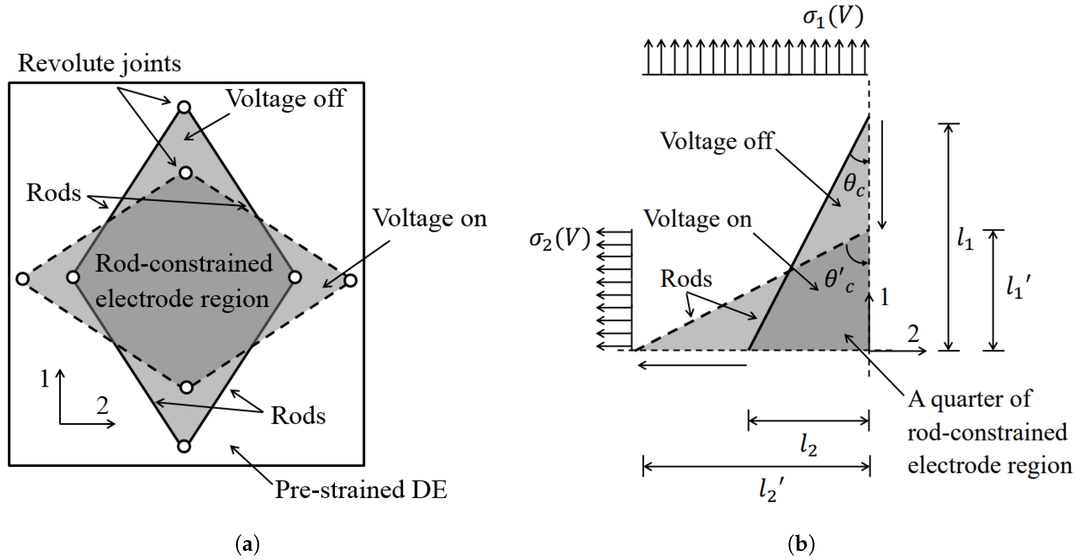
In the planar cDEA, the electrode regions are constrained by rods at edges, which are free to rotate relative to each other. Thus the planar cDEA may deform from one rhombus shape to another during actuation as shown in Figure 1a. The actuation strains, s 1 and s 2 , are defined as changes in the lengths of rhombus diagonals between the un-actuated ( l 1 , 2 ) and actuated states ( l 1 , 2 ):
s 1 = λ 1 1 = l 1 l 1 l 1 s 2 = λ 2 1 = l 2 l 2 l 2
The constraining angle of the rod-constrained electrode region, θ c ( 0 ° < θ c < 90 ° ), is defined as the angle of the rod relative to Direction 1 as in Figure 1b.
cDEAs have two distinct states during actuation: the equilibirum state and the neutral state. The neutral state is defined as the state of planar cDEAs that any further increase in driving voltage will not generate actuation strains in both planar directions, which depends on a specific constraining angle under a given bi-axial pre-strain condition. The equilibrium state is the steady state that planar cDEAs, which are not in neutral state, reach during the actuation. When a driving voltage, V, is applied, the rod-constrained electrode region deforms according to the voltage-induced stresses, σ 1 ( V ) and σ 2 ( V ) and the constraining angle changes from θ c to θ c ( 0 ° < θ c < 90 ° ) as in Figure 1b. In an ideal scenario, a cDEA is driven by sufficiently high voltage without the occurrence of electrical breakdown and off-plane deformation. Then the rod-constrained electrode region deforms until it reaches the neutral state with the constraining angle, θ n ( 0 ° < θ n < 90 ° ), where reorientation of the rods brings equilibrium between planar stresses in planar directions. In the neutral state, further increase in driving voltage does not change the constraining angle further ( θ c = θ n ) but only causes off-plane deformations in both planar directions. In reality, when a planar cDEA is driven by low voltages (∼kV, causing in-plane expansion only), the rod-constrained electrode region deforms and reaches a equilibrium state instead of the neutral state ( | θ c θ n | > | θ c θ n | ).
The neutral state of a planar cDEA depends on the bi-axial pre-strain condition. When a planar cDEA has equal bi-axial pre-strains ( λ p 1 = λ p 2 ), the electrodes tends to expand in both planar directions equally, resulting the neutral state has the constraining angle θ n = 45 ° . When the rod-constraining configuration matches this neutral state, no contraction and extension strains would be generated during actuation ( θ c = θ c = θ n = 45 ° ). In most cases where θ c 45 ° , actuation strains in planar directions are symmetric about θ n (i.e., s 1 | θ c = 60 ° = s 2 | θ c = 30 ° ). When a planar cDEA has biased bi-axial pre-strains ( λ p 1 < λ p 2 ), the neutral state has an increased constraining angle as θ n > 45 ° . In the case θ c = θ n , no actuation strains are generated during actuation; in other cases θ c θ n , the contraction and extension in planar directions occur but are no longer symmetric about θ n (i.e., s 1 | θ c = 60 ° s 2 | θ c = 30 ° ).
The exception happens when off-plane deformation occurs only in Direction 1 under high driving voltages (∼kV, causing off-plane expansion). Planar stress in Direction 1 is significantly reduced as σ 1 0 , and the voltage-induced stress in Direction 2, σ 2 , dominates the equilibrium of planar stress. The neutral state no longer restricts deformation and larger change in constraining angle may occur, causing significant increase in extension strain, s 2 ( V ) , and contraction strain, s 1 ( V ) , compared with the case without off-plane deformation at low driving voltages (∼ kV), as in Lee and Tawfick’s work [24].

3. Experimental Procedure

To investigate and explore the potential of a planar cDEA in performing planar contraction, three sets of experiments were carried out as follows:
  • Measure the effect of constraining angle θ c on contraction strain under an equal bi-axial pre-strain condition.
  • Measure the effect of biased bi-axial pre-strain on contraction strain under the same rod-constraining as in 1.
  • Measure the contraction force with optimized rod-constraining and a bi-axial pre-strain condition.
The DE was VHB 4910 from 3MTM in a basic 1 mm thick film format. The electrode material was carbon black grease from MG ChemicalsTM. The steel rods for motion-constraining had a diameter of 1 mm.

3.1. Experiment 1

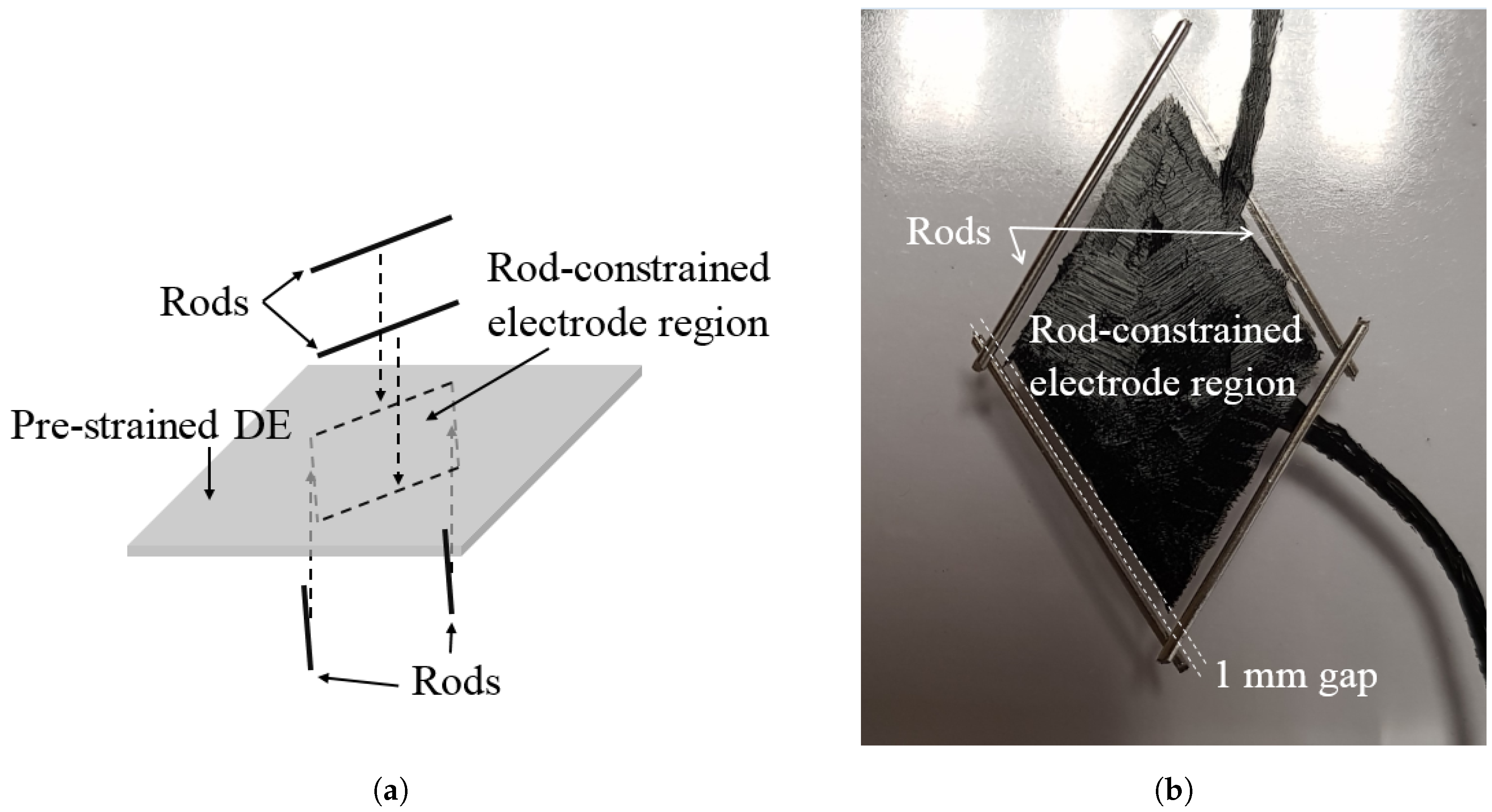
The DE was cut into square areas 35 mm × 35 mm, which were then pre-strained by 300% in both planar directions ( λ p 1 = λ p 2 = 3 , leading to an overall planar pre-strain of 900 % ) and clamped onto a rigid frame of size 100 mm × 100 mm. Four rods were placed on the pre-strained DE to form a rhombus-shaped region in edge length 20 mm as shown in Figure 2a. Two pairs of rods of length 22 mm were applied on both sides of the DE. Rods were configured to be longer than the edge length to ensure that the four corners were constrained on both sides and could rotate only. This is essential for achieving planar contraction strain. Figure 2b shows that the actual sample has the electrode region with a small gap of approximately 1 mm between the pair of rods on each side. Such a configuration prevents premature failure (i.e., electrical breakdown) by avoiding applying driving voltage. This is due to:
  • The conductive rods (i.e., no electrical field on the constrained corners).
  • The regions of the DE close to corners that are distorted significantly during actuation (i.e., less stress concentration due to actuation).
In this experiment, because samples were pre-strained equally in planar directions, constraining angles of 10 ° , 20 ° , 30 ° , 40 ° and 45 ° were tested. At each constraining angle, the actuations were driven by voltages of 1 kV, 2 kV, 3 kV and 4 kV.

3.2. Experiment 2

The DE was cut into rectangular areas of 52 mm × 25 mm, which were then pre-strained by 200% in Direction 1 ( λ p 1 = 2 ) and 450% in Direction 2 ( λ p 2 = 4 . 5 ). The same configurations of rods, electrode arrangement and driving voltages were applied on samples. Because the samples have the same overall pre-strain of 900% ( λ p 1 λ p 2 = 9 ) as in Experiment 1, the same driving voltage leads to the same electrical field on the planar cDEA. Constraining angles of 10 ° , 20 ° , 30 ° , 40 ° , 45 ° , 50 ° , 60 ° , 70 ° and 80 ° were tested in this experiment. At each constraining angle, the specimen was driven by voltages of 1 kV, 2 kV, 3 kV and 4 kV.

3.3. Experiment 3

In order to demonstrate contractile force actuation, modified planar cDEAs, under both equal and biased bi-axial pre-strain conditions and the identified constraining angles that generate the largest contraction strains from Experiments 1 and 2, were tested. The configurations of rods, electrode arrangement and driving voltages remained the same. A rigid frame was added to the structure to hold cDEAs in pre-strain in Direction 2.
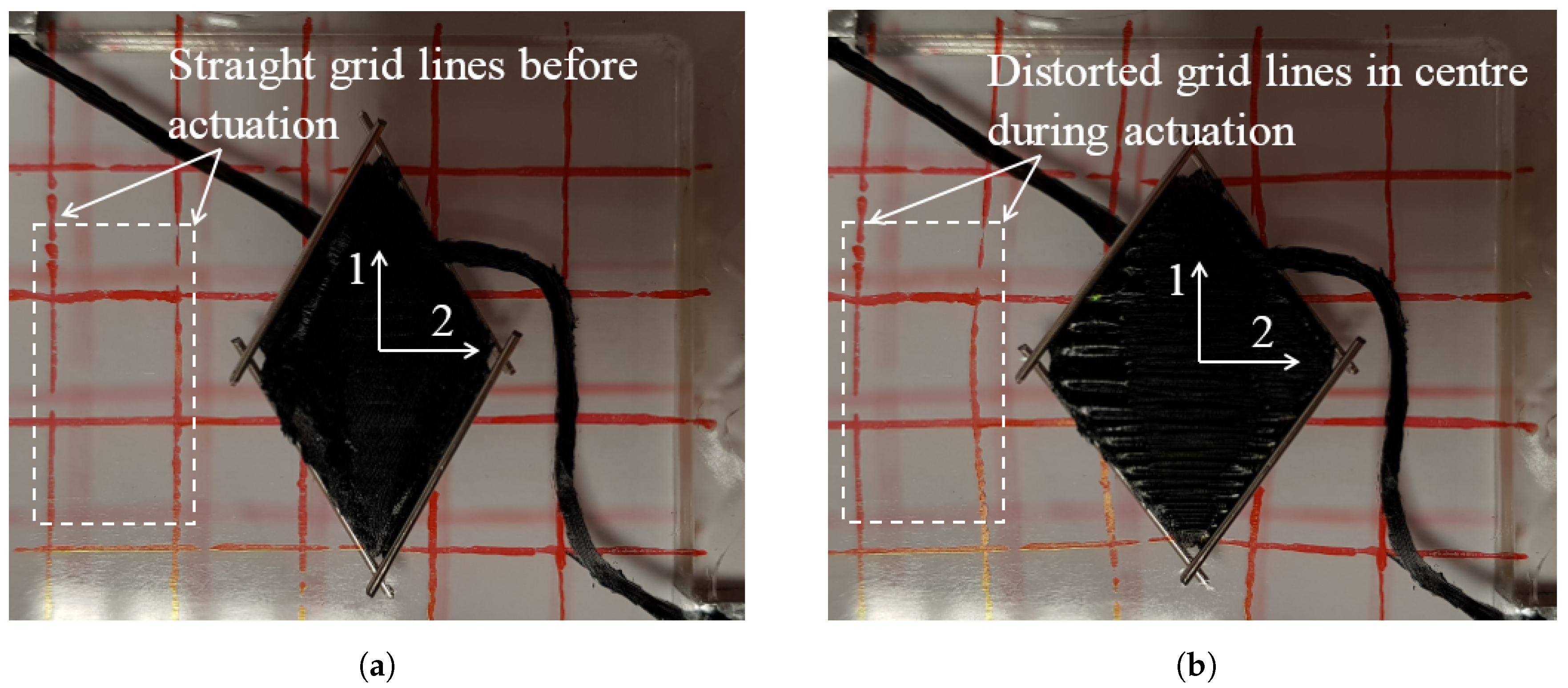
The design of the rigid frame was guided by a preliminary investigation to understand the field of deformation around rod constrained electrode region in the planar cDEA as in Figure 3. The pre-strained DE was marked in a grid of cell sizes of 10 mm × 10 mm before being fabricated fully into the planar cDEA as in Figure 3a. Figure 3b shows that inactive region extends in Direction 1 and contracts in Direction 2 for the planar cDEA during actuation. The distorted grid lines show that deformation of the inactive region occurs mainly at corners of the rod-constrained electrode region and diminishes further away. Therefore, for an effective planar cDEA to generate contractile force, it is essential to:
  • Eliminate the inactive region in Direction 1 to ensure that no contraction strains are dissipated by the inactive region.
  • Preserve a sufficient inactive region around rod-constrained corners in Direction 2 to allow extension strain to occur in-plane.
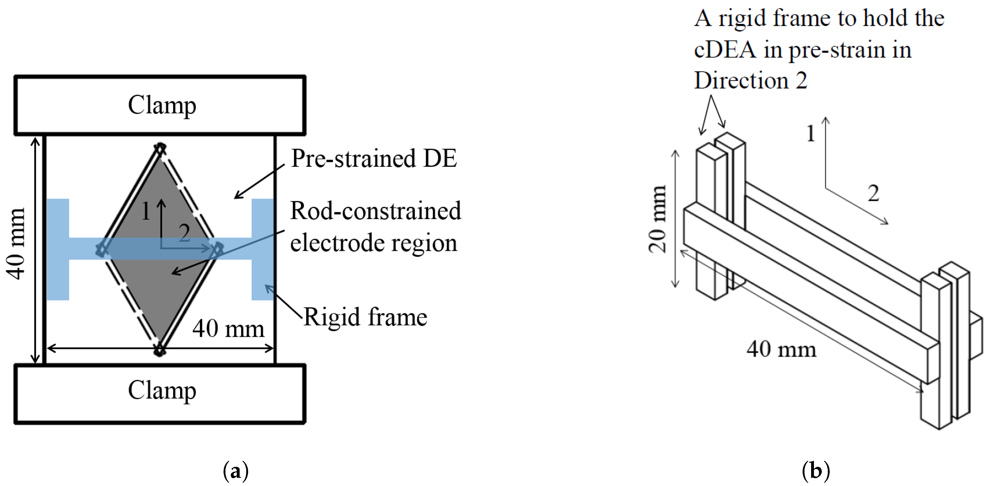
Figure 4a shows the configuration of the implemented cDEA for contractile force actuation. The width of the DE was set to be 40 mm and clamps, which were used to mount the planar cDEA onto the test rig, were placed close to electrode regions in Direction 1. A pair of frame as shown in Figure 4b was made of acrylate and placed on both sides of the planar cDEA to hold λ p 2 in the centre of structure (i.e., next to the rod-constrained corners).
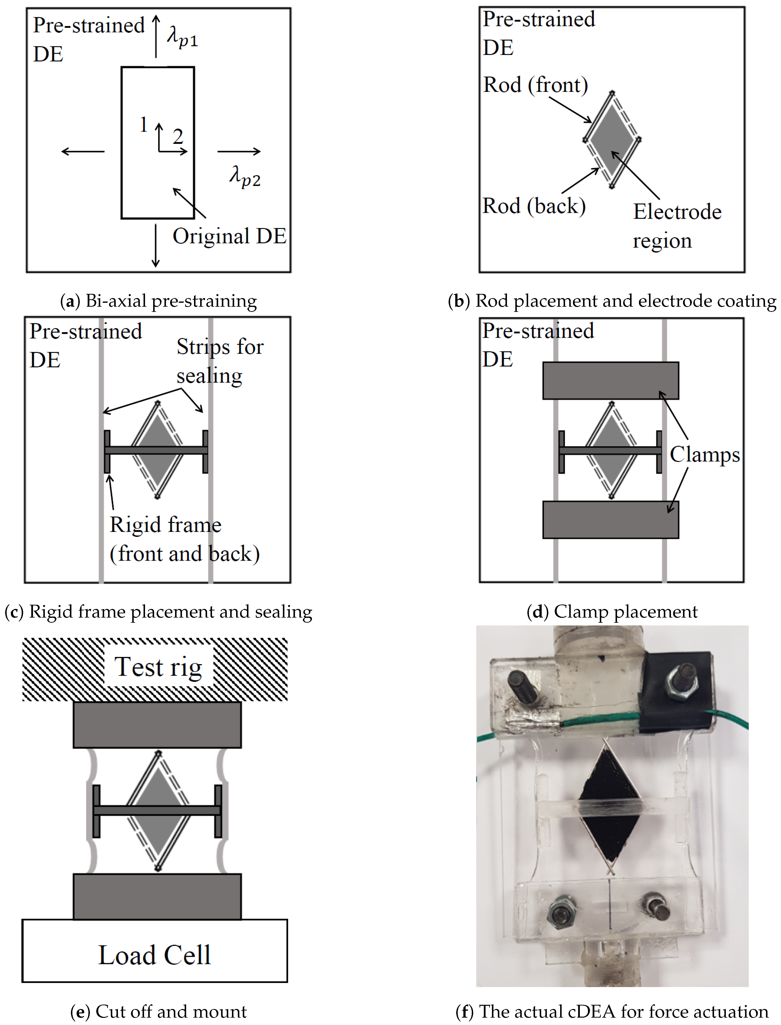
The detailed fabrication process steps are shown in Figure 5. When the DE was pre-strained largely in planar directions, it became specifically notch-sensitive (i.e., small cuts and defects propagate rapidly) and was difficult to maintain the configured shape. A pair of VHB 4910 strips was added on both sides of the pre-strained DE as shown in Figure 5c. They acted as boundaries to stop any defects from propagating. To be consistent, the strips were pre-strained as for the planar cDEA in Direction 1 ( λ p 1 = 2 ). In Figure 5d,e, one halves of the clamps were applied prior to DE cutting in alignment with an additional frame, which was used to preserve the overall shape of the planar cDEA before mounting in the test rig. The second halves of the clamps were applied after DE cutting, and the additional frame was removed after the planar cDEA was mounted in the test rig.

3.4. Measurement System Setup

For Experiments 1 and 2, the states of the planar cDEA were recorded by a camera, which had a fixed position during experiments. For Experiment 3, modified planar cDEAs were fixed to the test rig on the top and mounted onto a load cell on the bottom. The load cell was customized to measure small forces up to 5 N. Voltages were applied to the samples in various sequences and the force was measured by the load cell throughout.
A high-voltage (HV) generator, based on a HV DC-DC converter (module 15A24 from PPMTM), was used to amplify the input voltage (0–5 V) to the voltage output (0–15 kV). In Experiment 3, the actual voltage output was also measured using a built-in channel from the HV module.

4. Results and Discussions

4.1. Effect of Constraining Angle θ c

Figure 6 summarizes the measured actuation strains of the planar cDEA over a range of θ c at 4 kV. The s 1 and s 2 data are symmetric about 45 ° because pre-strains are equal in planar directions. In Direction 1, contraction occurred when 0 ° < θ c < 45 ° , and at θ c = 20 ° , the contraction strain reaches a maximum at 7%. Extension strain occurred when 45 ° < θ c < 90 ° . It increases as θ c increases and reaches a maximum at 80% at θ c = 80 ° . It shows that when the rod-constrained electrode region is actuated, it tends to restore the neutral state as a square shape with θ n = 45 ° , causing the longer diagonal to contract and the shorter diagonal to extend. Noting that at θ c = 0 ° and 90 ° , the electrode region is constrained fully in both planar directions, causing no actuation strains under driving voltages ( s 1 = s 2 = 0 ).
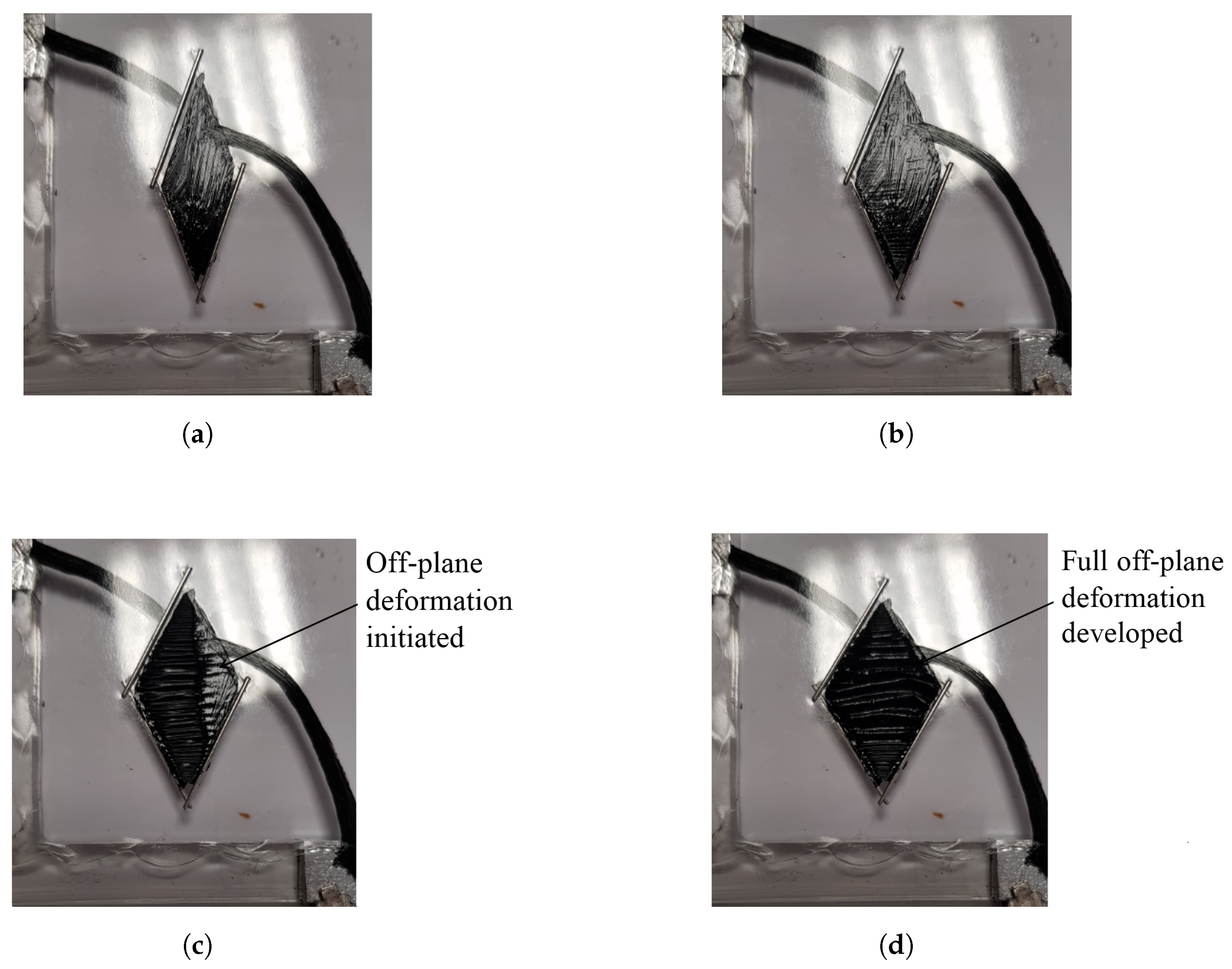
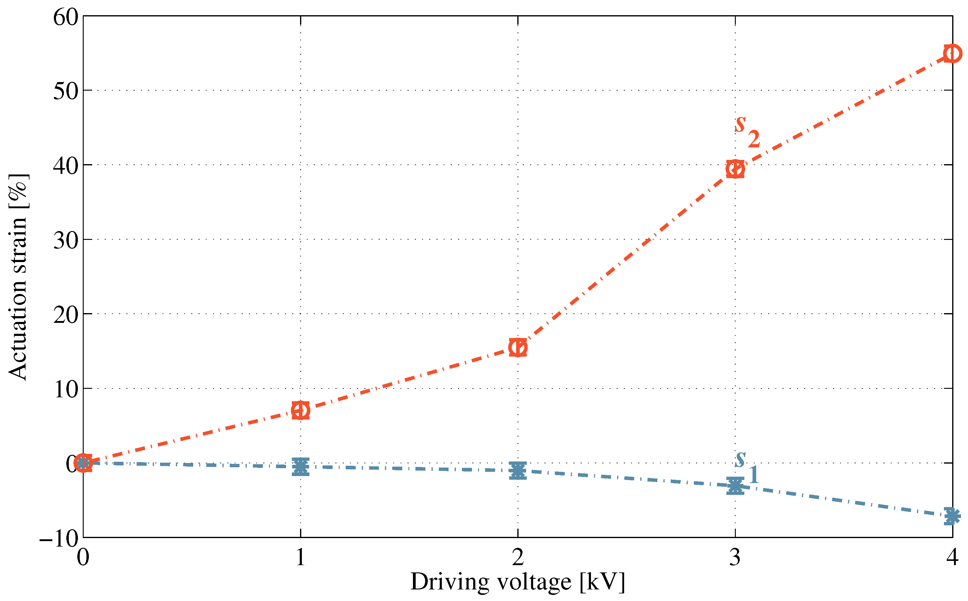
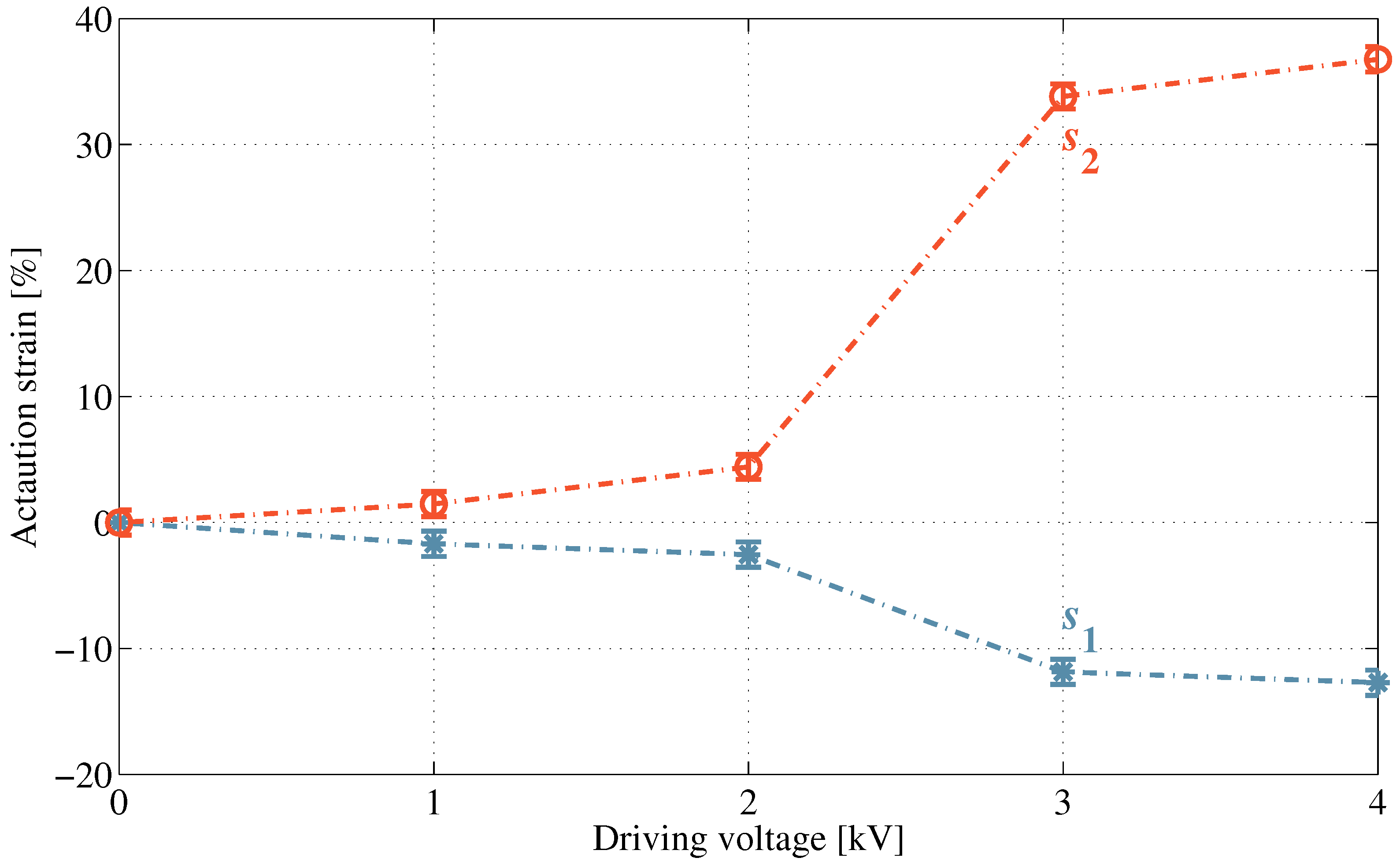
Figure 7 shows the state of the planar cDEA with θ c = 20 ° at 0 kV, 2 kV, 3 kV and 4 kV. The corresponding actuation strains, s 1 and s 2 at each driving voltage, are summarized in Figure 8. At driving voltages up to 2 kV, voltage-induced tension forces in Directions 1 and 2 counteract each other, and deformation of the rod-constrained electrode region is small as seen in Figure 7b. At 3 kV and 4 kV, as in Figure 7c,d, off-plane deformation (i.e., wrinkling) occurred in Direction 1, which caused the rod-constrained electrode region to lose tension in Direction 1 and deform mainly due to voltage-induced extension force in Direction 2. The actuation strains, s 1 and s 2 , therefore increased significantly as shown in Figure 8.
The results of cDEAs incorporating the effect of off-plane deformation agree with Lee and Tawfick’s work [24], in which they reported the same relationship between actuation strains and constraining angles at low driving voltage of 1.5 kV (i.e., without off-plane deformation), and the maximum contraction strain of 6.3% with θ c = 22 ° at 7 kV. They also demonstrated that the derived equations agree well with the measurement results when no electromechanical instability occurs. The derived equations do not take off-plane deformation and loss of tension into account. Therefore a more sophisticated model is required to predict the contraction of the planar cDEA at high driving voltages. It is noted that large pre-stretch ( λ p > 1 . 5 ) leads to large actuation strain in DEAs by suppressing electromechanical instability [29,30]. The observed off-plane deformations in this work and in Tawfick’s work are therefore due to loss of tension, not electromechanical instability. Moreover, in experiments, the frame was placed relatively close to the electrode region as shown in Figure 7. It is possible to enhance actuation strains further by increasing the size ratios of the passive regions and the frame to the electrode region [30]. However, it is not feasible to do so in practical applications (i.e., force actuation) without exploiting the maximum actuation capability of DEAs.

4.2. Effect of Biased Bi-Axial Pre-Strain

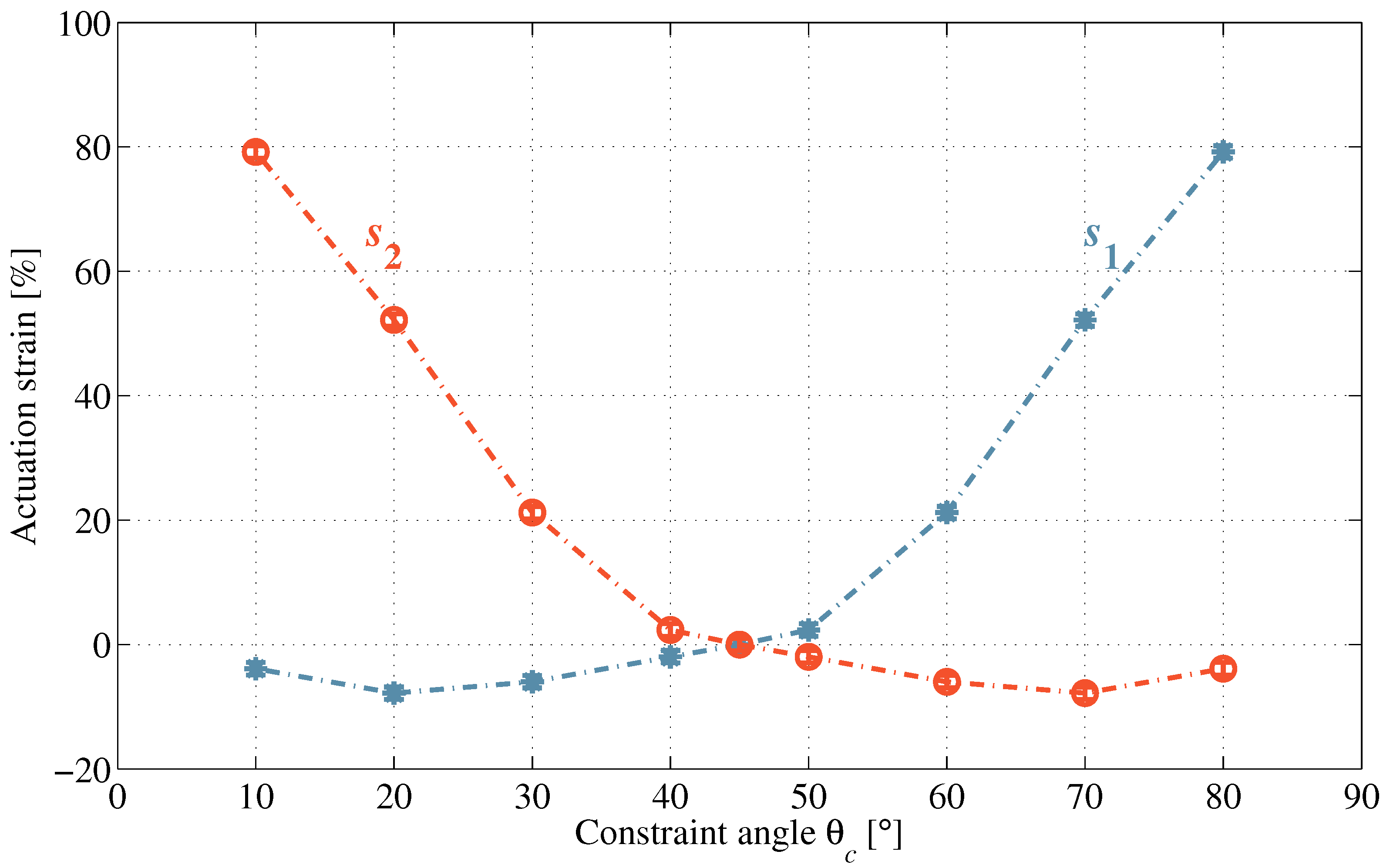
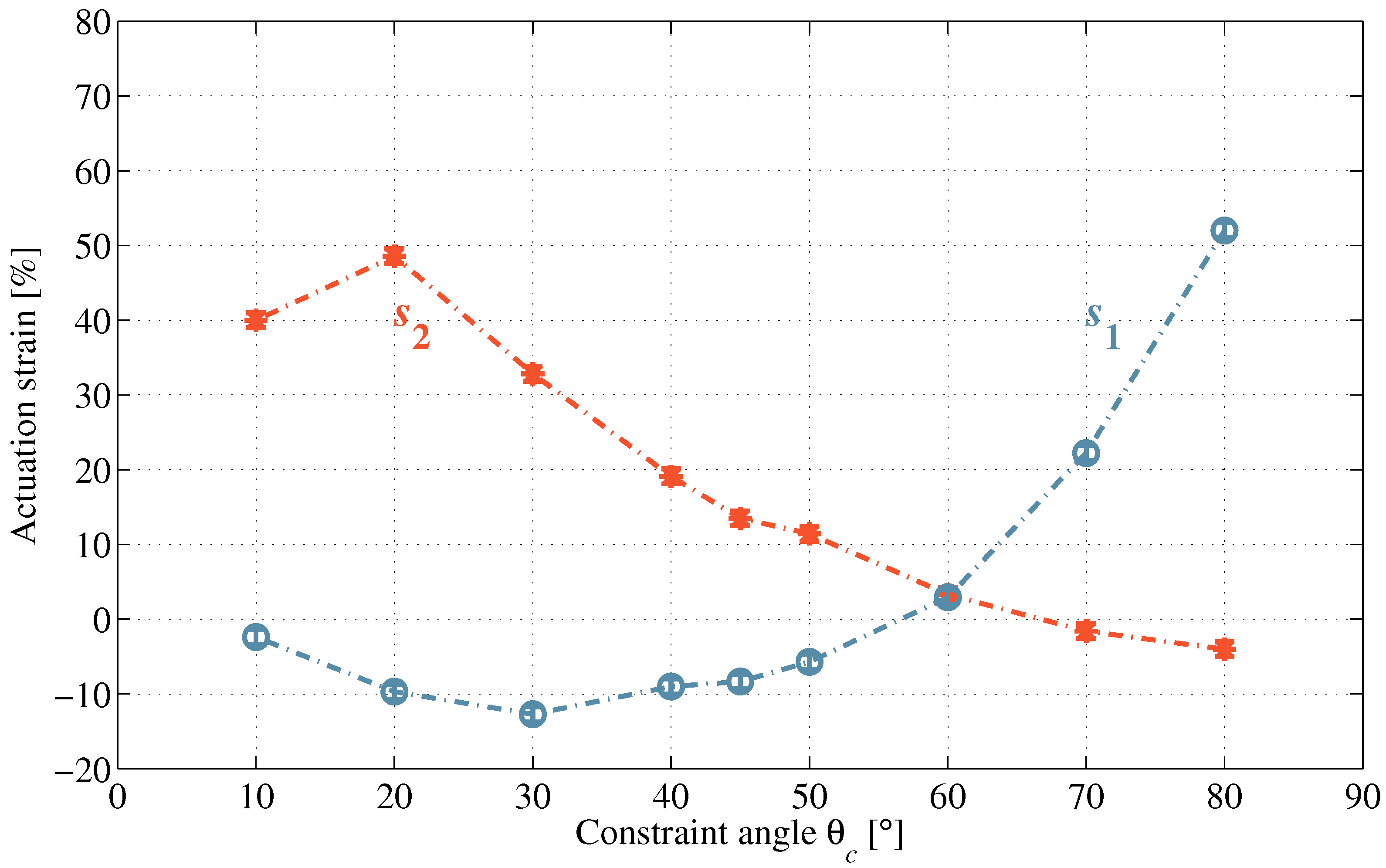
Figure 9 summarizes the measured actuation strains of the planar cDEA over the same range of θ c at 4 kV with biased bi-axial pre-strains λ p 1 = 2 and λ p 2 = 4 . 5 . Because pre-strains are different in the planar directions, the s 1 and s 2 curves are no longer symmetric as seen in Figure 6. Furthermore, two curves intersect at θ c = 60 ° with s 1 = s 2 = 0 , approximately, suggesting that the neutral state of the rod-constrained electrode region has changed from θ n = 45 ° to 60 ° . In Direction 1, contraction strain occurs when 0 ° < θ c < 60 ° and reaches a maximum of 13% at θ c = 30 ° ; extension strain occurs when 60 ° < θ c < 90 ° and reaches a maximum of 53% at θ c = 80 ° . In Direction 2, extension strain reaches a maximum of 48% at θ c = 30 ° and contraction strain reaches a maximum of 3% at θ c = 80 ° .
Given the same overall planar pre-strain ( λ p 1 λ p 2 = 9 ), the cDEA under biased bi-axial pre-strains generates contraction strain approximately twice (13% compared with 7%) that under equal bi-axial pre-strains at the same driving voltage. The reason is that the isotropic DE becomes anisotropic and has a higher elastic modulus in the more pre-strained direction, causing voltage-driven deformation to occur preferably in the perpendicular direction [27,28]. Voltage-induced stress in Direction 1 ( λ p 1 = 2 ) is higher relative to that in Direction 2 ( λ p 2 = 4 . 5 ) and prestrain-induced stress in Direction 1 is lower relative to that in Direction 2, causing the rod-constrained electrode region to deform more before reaching its equilibrium state. Hence, different bi-axial pre-strains cause out-of-balance between actuation forces in planar directions, so that more contraction strain can be generated from the planar cDEA.
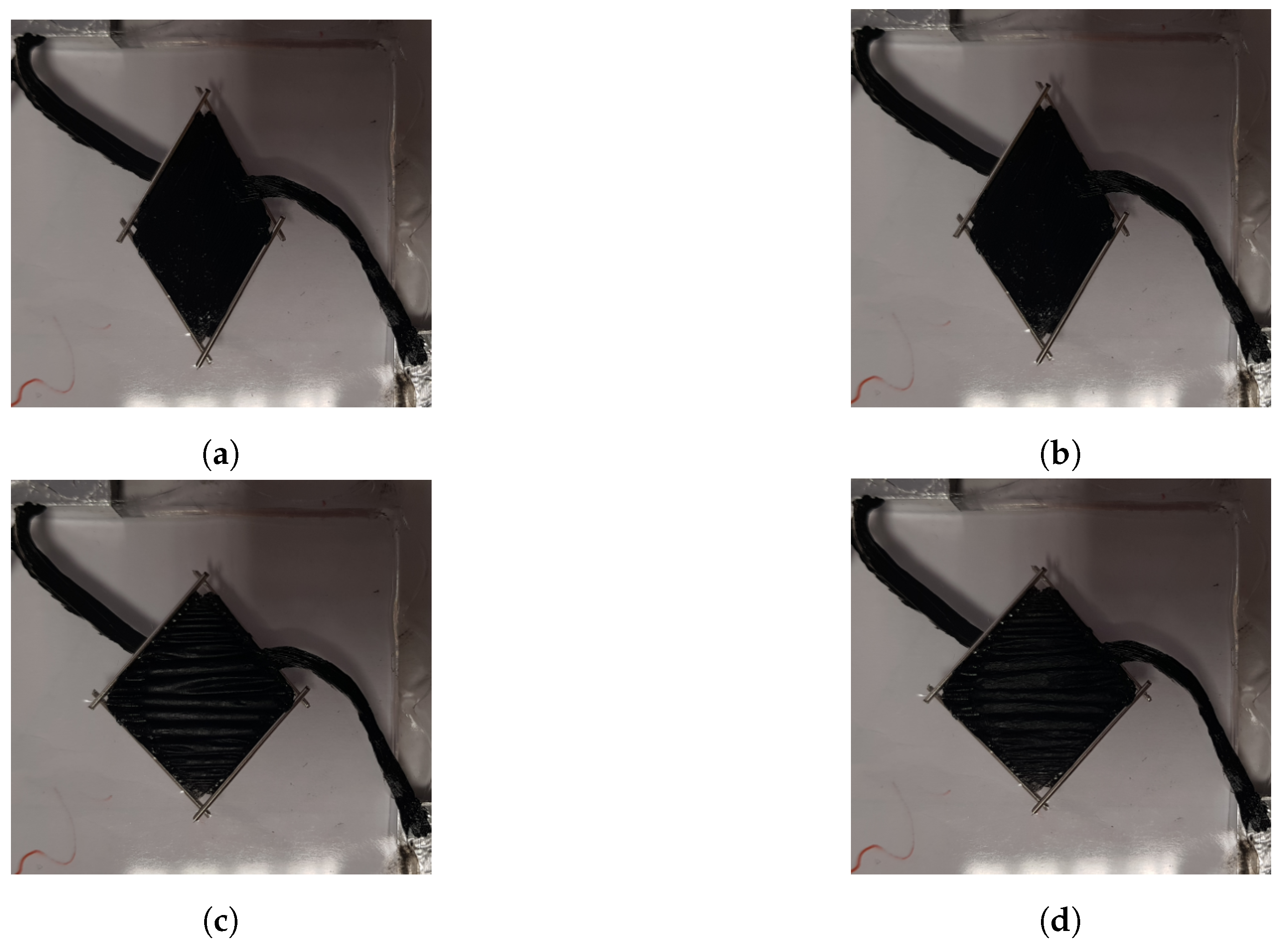
Figure 10 shows the state of the planar cDEA with θ c = 30 ° at 0 kV, 2 kV, 3kV and 4 kV. Figure 11 summarizes the corresponding actuation strains at these driving voltages. The off-plane deformation also occurs at 3 kV and propagates further at 4 kV as shown in Figure 10c,d. The same significant increases in both extension strains (5% to 34%) and contraction strains (2% to 11%) are observed passing from 2 kV to 3 kV. When an electrode region loses tension in Direction 1, the contraction motion mainly depends on extension in Direction 2, resulting in higher contraction strain.

4.3. Modified cDEA for Contractile Force Actuation

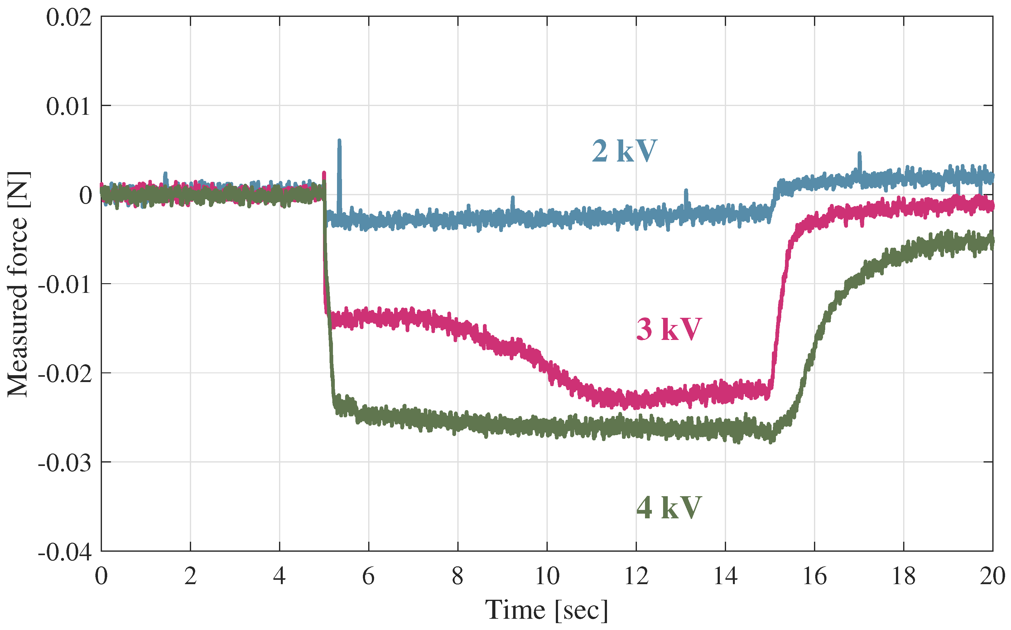
Figure 12 shows measured forces of the modified planar cDEA with equal bi-axial pre-strains at 2 kV, 3 kV and 4 kV. The driving voltage, V, had a step-up, step-down profile:
V = 0 , 0 s t 5 s V s t e p , 5 s < t 15 s 0 , 15 s < t 20 s
In addition, the modified planar cDEA responds relatively slowly from contraction motion because of the strong viscoelastic behaviour of the VHB 4910. By comparing the states at t = 0 s to t = 15 s, contraction forces were 0.003 N at 2 kV, 0.022 N at 3 kV and 0.026 N at 4 kV. The dramatic increases in contraction forces at 3 kV and 4 kV are due to occurrence of off-plane deformation in Direction 1 and agree well with the observations in Figure 7.
The force measurement results prove that the occurrence of off-plane deformation in Direction 1 is due to a combination of local off-plane deformation and voltage-induced contraction in Direction 1. Because it is difficult to have electrode material applied uniformly over the electrode region, it causes concentration of the electrical field in localities across the electrode region. As a result, these localities deform more than the surrounding region and initiate local off-plane deformations. Such a phenomenon can be also observed in conventional DEAs without motion constraining. It occurs quickly in both planar directions and does not necessarily lead to electrical breakdown (i.e., different from electromechanical instability as being described in Lee and Tawfick’s work [24]). However, unlike conventional DEAs, planar cDEAs contract in Direction 1. Because the electrode region in thin sheet format cannot sustain compressive force (i.e., due to buckling and geometrical factors), local off-plane deformation propagates to the entire rod-constrained electrode region. Such a process can be observed as the long-term transition of contraction force that lasts for 8 s at 3 kV as shown in Figure 12. These observations of propagation of off-plane deformation also agree with the prediction of Type-I wrinkling in Zhu’s work for DEAs with bi-axial pre-strains ( λ p 1 = 2 and λ p 2 = 4 ) [31]. However, unlike the configuration in Zhu’s work, the electrode region in planar cDEAs is constrained fully. At higher driving voltages, the flat part of the electrode region, which coexists with the wrinkled part of the electrode region in Type-I wrinkling at relatively low driving voltages, buckles due to the constraints. Therefore, a different transition was observed at 4 kV.
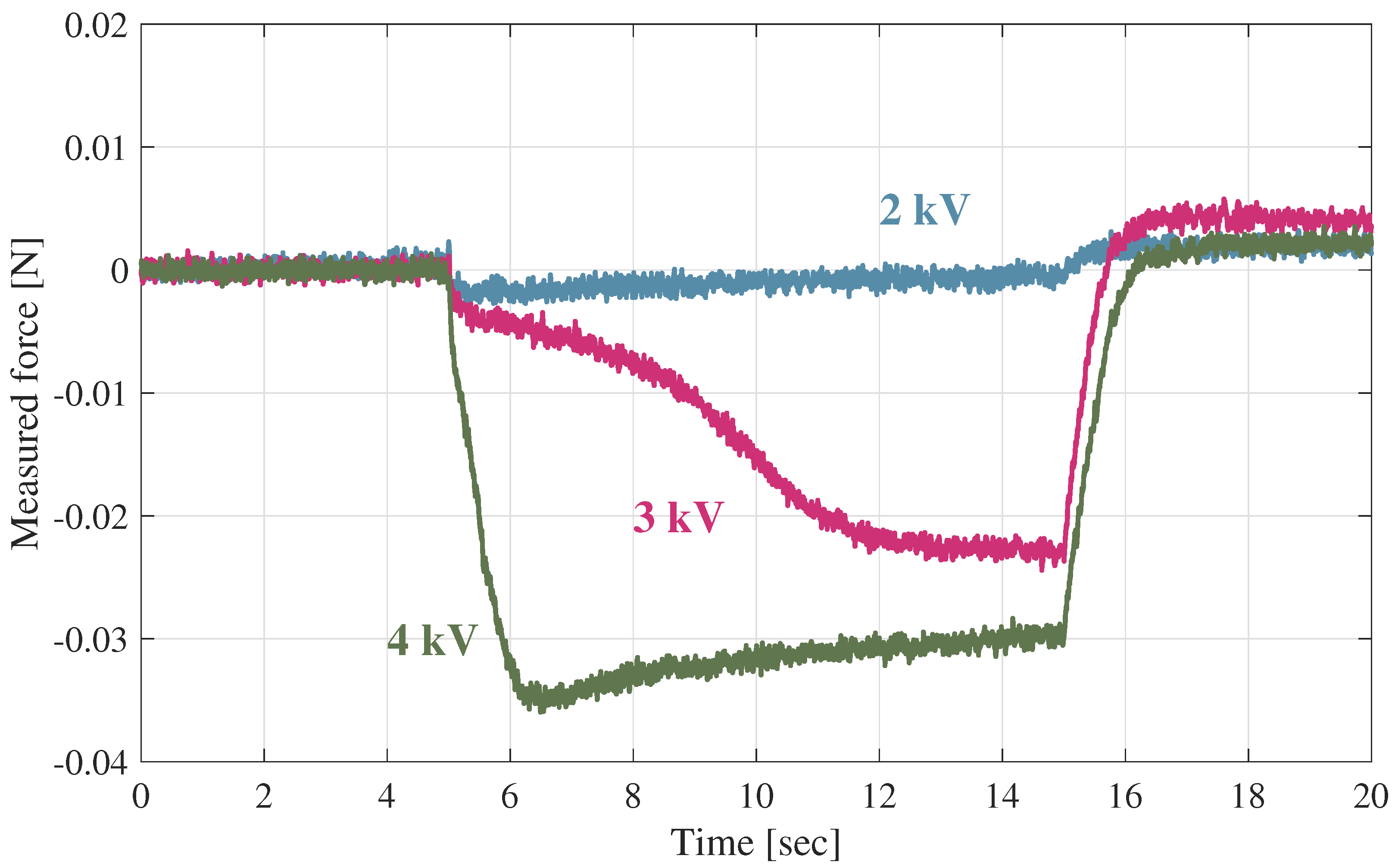
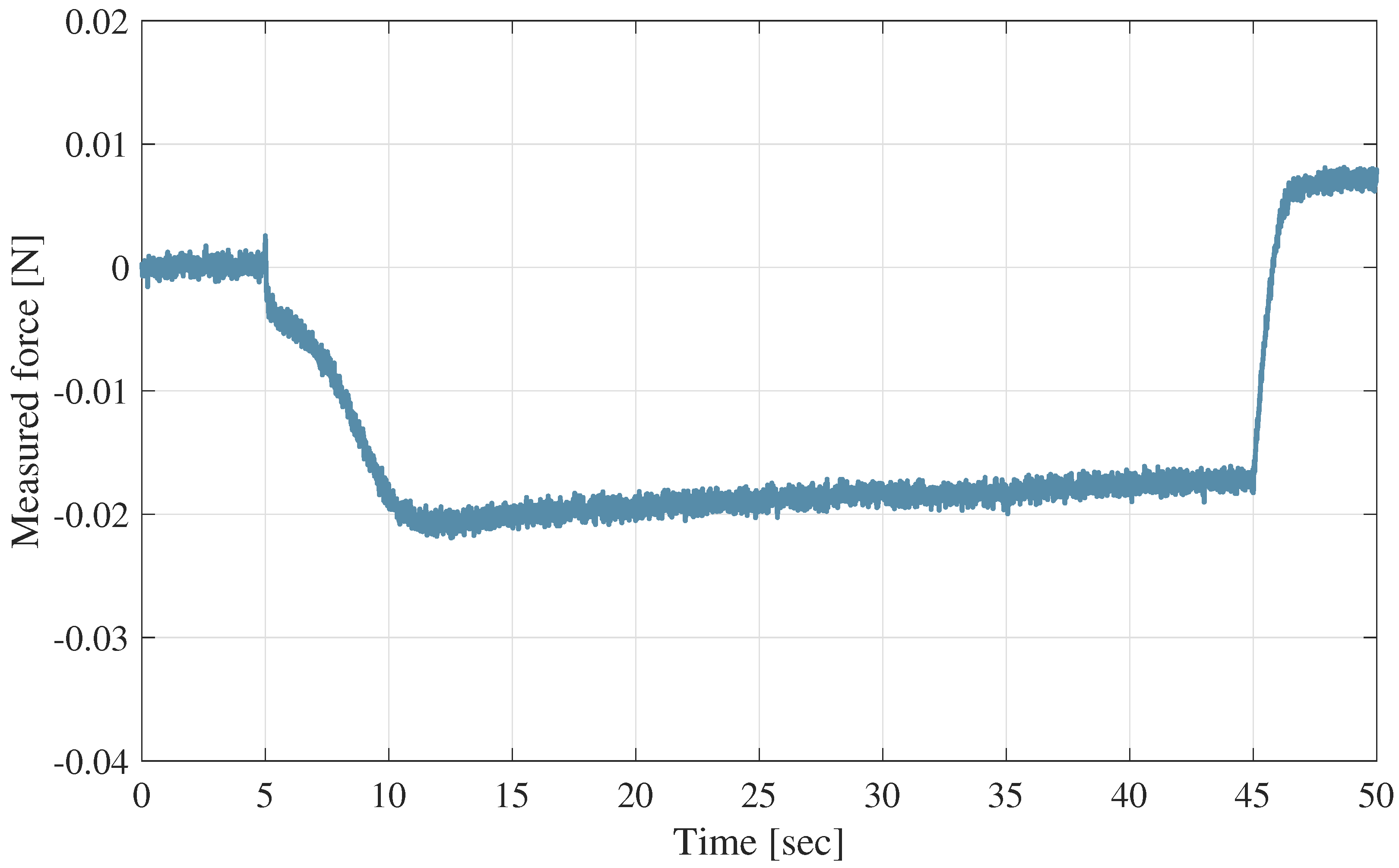
Figure 13 shows measured forces of the modified planar cDEA with biased bi-axial pre-strains at 2 kV, 3 kV and 4 kV. The contraction forces were measured at 0.002 N, 0.023 N and 0.03 N, respectively. While biased bi-axial pre-strains give larger contraction forces compared with those from equal bi-axial pre-strains (0.03 N compared with 0.026 N), the difference is less than that with contraction strains (13% compared with 7%). The primary reason is that the rod-constrained electrode regions have different dimensions in planar directions under the different rod-constraining configurations. A secondary reason is relaxation, which occurs in the opposite direction to contraction and found to have more effect on the biased bi-axial pre-strain condition. At 4 kV, the contraction force reaches a maximum of 0.035 N at t = 6 . 5 s and relaxes to 0.03 N slowly. Figure 14 shows the measured force of the modified planar cDEA over 50 s. It confirms that the relaxation occurs at 3 kV continuously throughout the actuation period.

4.4. Stability and Failure

The experiments showed that the planar cDEA survived the driving voltage of 4 kV, but failed at 5 kV. Such an observation remains consistent for different constraining angles and different bi-axial pre-straining conditions (given the same overall planar pre-strain). Failure of the planar cDEAs has two modes:
(a)
Delamination of the rods at corners, and
(b)
Electrical breakdown within the electrode region.
Because the presented planar cDEAs have large pre-strains ( λ p 1 , p 2 > 1 . 5 ), electromechanical instability is suppressed and large actuation strains are achieved [29,30]. Therefore at critical driving voltages, although the failure and off-plane deformation appear simultaneously in the rod-constrained electrode region, the failure mode is electrical breakdown. Due to the adhesive nature of VHB 4910, rods were placed directly onto the DE material. At corners, where rods from both sides of the DE overlap, the bonding is vital to make corners act like revolute hinges. A failure mode rarely occurs with the current configuration ( λ p 1 λ p 2 = 900 % ), but may become more common when having larger planar pre-strain (i.e., the adhesive layer on the VHB 4910 becomes thinner) and more biased bi-axial pre-strains (i.e., larger deformation in electrode region and distortion at corners).
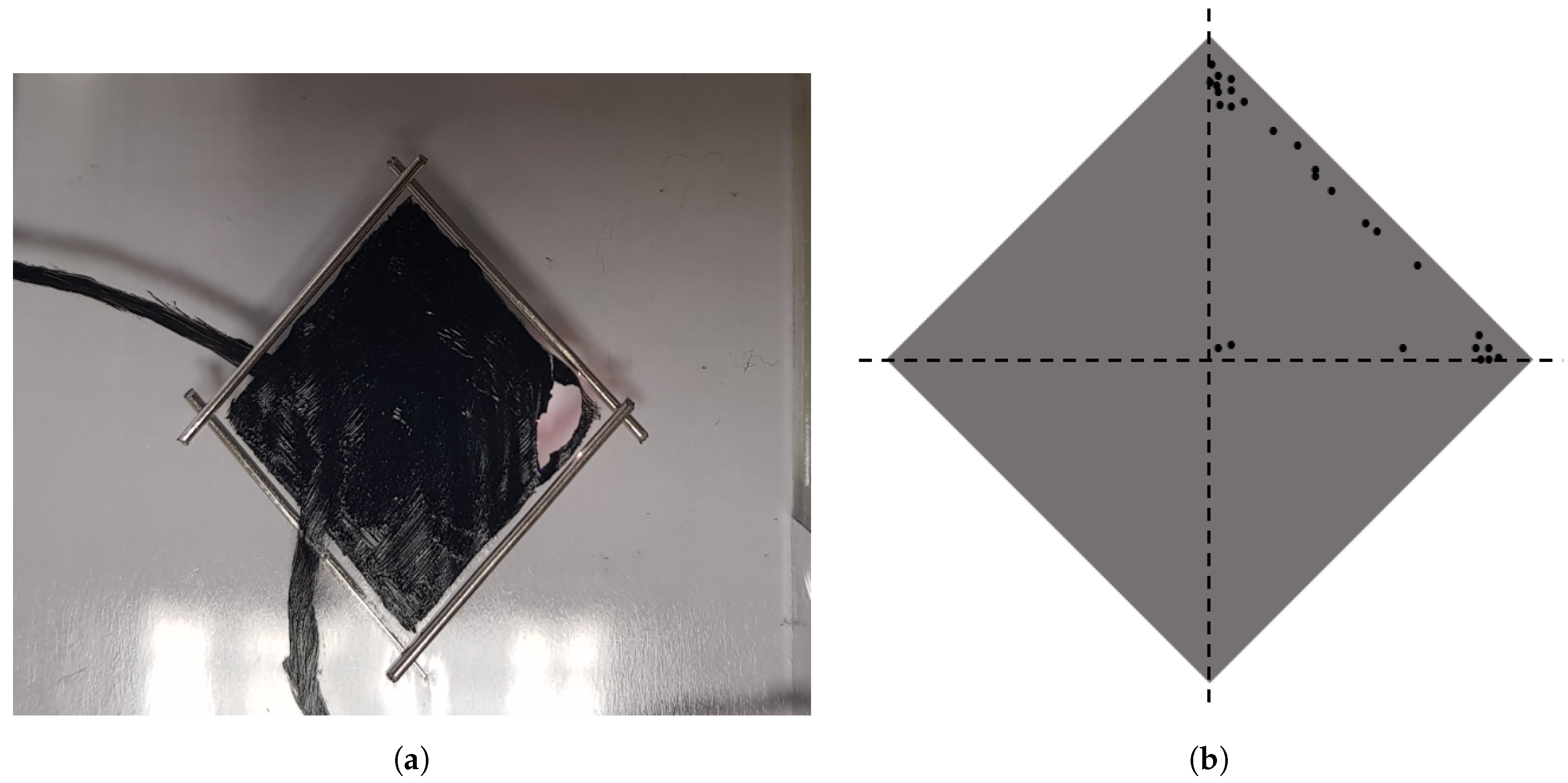
Figure 15a shows the occurrence of electrical breakdown in the planar cDEA. Once the initial electrical breakdown occurs, the rupture at one locality propagates quickly to become a large hole, but is confined within the rod-constrained region. Given that small defects and cuts often propagate rapidly in the VHB 4910 with larger planar pre-strains, such a feature would be beneficial in a complex system with multiple DEAs because it would isolate the failure of an actuator and minimize the structural damage to the entire system.
Figure 15b summarizes the failure localities of the planar cDEA over 27 samples at 5 kV (3 samples for each constraining angle). It is assumed that constraining angle has no effect on the occurrence of electrical breakdown. The failure spots were therefore marked only in a quarter of the electrode region. The results show that the majority of failure spots are close to corners, where the planar cDEA distorts the most during contraction. Apart from that, some failures occurred along the edges, where additional electrode material (i.e., thicker electrode layer causes concentration of electrical field) was applied for connection to high voltage power supply. Only a few failures occurred in the centre of the electrode region. The stability of the planar cDEA therefore can be improved by keeping the electrode region further away from corners. However, whether such an electrode rearrangement would compromise the contraction performance has yet to be studied.

4.5. Patterned cDEAs

When off-plane deformation occurs in Direction 1, it is beneficial because the resulting loss of tension allows the rod-constrained electrode region to contract under extension in the lateral direction. When off-plane deformation also occurs in Direction 2, it is terminal because loss of tension in both planar directions will not deform rod-constrained electrode region in plane. In this work, no electromechanical instability was observed in Direction 2 and all planar cDEAs failed primarily due to electrical breakdown. It is possible to have the driving voltage controlled in order to maximize the extension strain in Direction 2, but it only improves contraction strain of the planar cDEA when extension strain remains in plane (i.e., higher driving voltage does not necessarily mean higher contraction strain).
As shown Figure 3, pre-strained inactive regions in Direction 2 contract to keep the extension strain in-plane during actuation. It is therefore essential, when designing the modified planar cDEA for contractile force actuation, to preserve an inactive region in Direction 2. In Lee and Tawfick’s work [24], fibre-constraints were applied in a web format across the entire electrode region, where each cell is similar to the enclosed rod-constrained region in this work. All cells, next to each other, have electrode material covered and performs actuation simultaneously. With this fibre reinforcement configuration, the overall contraction strains they have achieved are evidently less than that presented in this paper. Their study is also limited to be at low driving voltages because loss of tension, which was incorrectly mentioned as ’electromechanical instability’ occurs at higher driving voltages. Though it is not mentioned in their paper, loss of tension evidently did not benefit the generation of contraction strain.It is noted that it is possible for off-plane deformation, which is due to loss of tension rather than electromechanical instability, to occur only in one direction. This benefits contraction strain even when the DE has equal bi-axial pre-strains as in Figure 7. It is likely that in their web patterned cDEAs, off-plane deformations occurred in both planar directions and therefore did not benefit contractile actuation. One possible reason is having no inactive regions along the direction of extension. Because the neighbouring cells have identical configurations, at high driving voltages they generate same large extension strains (over 50%) simultaneously in Direction 2. For the same reason, in a web-patterned cDEA, despite of having identical configuration for each cell, they may, depending on their location, deform differently (i.e., cells in the centre has off-plane deformation while cells close to edges contract).
In Direction 1, because of the contraction, having cells next to each other is not problematic. Moreover, it is beneficial because no contraction strain would be dissipated by the inactive region, especially since the DE is viscoelastic. The fabricated cDEA in this work has a single electrode region and aspect ratio of 1:1 (40 mm × 40 mm). By having electrode cells aligned in Direction 1 and inactive regions preserved in Direction 2, the structure of the planar cDEA can be made long and narrow with improved aspect ratio, just like muscle fibres, without compromising the contraction capability.

5. Conclusions

In this work, the structure of a planar cDEA that generates planar contraction has been studied. Compared with a conventional DEA, it has a rhombus-shaped electrode region with rods constrained on edges. Rods overlap at corners to form revolute joints, making them free to rotate relative to each other. Hence, when driving voltages are applied, the rod-constrained electrode region deforms from one rhombus shape to another, resulting in contraction in one planar direction and extension in another. The actuation strains depend on the constraining angle of rods relative to planar directions. There is a neutral state of rod constraining in planar cDEAs, where the orientation of rods brings equilibrium between voltage-induced planar stresses. When the rod-constraining configuration matches the neutral state, no in-plane actuation strains are detected, but only off-plane deformation will occur in both planar directions. When the rod-constraining configuration is not in the neutral state, the voltage-induced planar stresses, depending on driving voltages, cause rods to rotate until they reach an equilibrium orientation around the neutral state. The neutral state restricts the maximum contraction that could occur in a planar cDEA.
Two strategies that allow a planar cDEA to contract further are presented and discussed; namely, off-plane deformation and biased pre-straining. It was demonstrated that at high driving voltage, it is possible to make off-plane deformation occur only in the direction of contraction, causing voltage-induced planar stresses in this direction to decrease significantly. Voltage-induced planar stresses in the direction of extension therefore dominate the equilibrium and the neutral state no longer restricts deformation of the rod-constrained electrode region. It was also demonstrated that when a planar cDEA has biased bi-axial pre-strains, the rod-constrained electrode region deforms preferably in the more pre-strained direction. Then, the neutral state changed from θ n = 45 ° , as for equal bi-axial pre-strain condition, allowing larger deformation and further reorientation of rods. By incorporating these two cases, the planar cDEA is capable of generating twice the contraction strain than that reported previously.
The effectiveness of these strategies was demonstrated further in force actuation. A modified planar cDEA that has the same electrode arrangement was developed. In addition, a rigid frame was added to the structure to maintain the pre-train in the lateral direction to contraction. The results show that the voltage-induced contraction force is significantly larger at high driving voltages, with occurrence of off-plane deformation, than that at low driving voltage. Furthermore, better actuation capability of the cDEA with biased bi-axial pre-strains than that with equal bi-axial pre-strains is evident. The results show also propagation of off-plane deformation from a locality to the entire electrode region. It explains the significant increase in contraction strain at high driving voltages and proves that such off-plane deformation is entirely due to loss of tension, rather than electromechanical instability.
The stability and failure study of the planar cDEA shows that the common failure mode is electrical breakdown. The common failure locality is close to the corners, where the rod-constrained electrode region distorts the most. The stability of the planar cDEA can therefore be improved by having electrode regions away from corners. Finally, the planar cDEA can be rearranged into a long and narrow fibre-like format, having electrode cells aligned in direction of contraction. However, it is vital to preserve sufficient inactive regions around electrode cells in the direction of extension, which would otherwise cause an electrode cell to buckle in both planar directions and no contraction.
Author Contributions

P.K. is the supervisor of R.Z., P.K. and P.I. are from Centre for Power Transmission and Motion Control. They provided the guidance for the analysis and the design of the experiments. R.Z. performed the experiments and analyzed the data.

Funding

This work was funded by the EPSRC grant EP/P006930/1 Future Advanced Metrology Hub.

Conflicts of Interest

The authors declare no conflict of interest. The founding sponsors had no role in the design of the study; in the collection, analyses, or interpretation of data; in the writing of the manuscript, and in the decision to publish the results.

Abbreviations

The following abbreviations are used in this manuscript:
DEdielectric elastomer
EAPelectro-active polymer
DEAdielectric elastomer actuator
cDEAcontractile dielectric elastomer actuator

References

  1. Carpi, F.; De Rossi, D.; Kornbluh, R.; Pelrine, R.; Sommer-Larsen, P. Dielectric Elastomers as Electromechanical Transducers: Fundamentals, Materials, Devices, Models and Applications of an Emerging Electroactive Polymer Technology; Elsevier: Amsterdam, The Netherlands, 2008; p. 329. [Google Scholar]
  2. Li, T.; Zou, Z.; Mao, G.; Qu, S. Electromechanical bistable behavior of a novel dielectric elastomer actuator. Trans. ASME J. Appli. Mech. 2014, 81, 041019. [Google Scholar] [CrossRef]
  3. Mao, G.; Li, T.; Zou, Z.; Qu, S.; Shi, M. Prestretch effect on snap-through instability of short-length tubular elastomeric balloons under inflation. Int. J. Solids Struct. 2014, 51, 2109–2115. [Google Scholar] [CrossRef]
  4. Pei, Q.; Rosenthal, M.; Stanford, S.; Prahlad, H.; Pelrine, R. Multiple-degrees-of-freedom electroelastomer roll actuators. Smart Mater. Struct. 2004, 13, N86–N92. [Google Scholar] [CrossRef]
  5. Jung, K.; Koo, J.; Nam, J.D.; Lee, Y.; Choi, H. Artificial annelid robot driven by soft actuators. Bioinspir. Biomim. 2007, 2, S42–S49. [Google Scholar] [CrossRef] [PubMed]
  6. Shian, S.; Bertoldi, K.; Clarke, D. Use of aligned fibers to enhance the performance of dielectric elastomer inchworm robots. Electroact. Polym. Actuators Devices (EAPAD) 2015, 9430. [Google Scholar] [CrossRef]
  7. Anderson, I.; Gisby, T.; McKay, T.; O’Brien, B.; Calius, E. Multi-functional dielectric elastomer artificial muscles for soft and smart machines. J. Appl. Phys. 2012, 112. [Google Scholar] [CrossRef]
  8. Anderson, I.; Hale, T.; Gisby, T.; Inamura, T.; McKay, T.; O’Brien, B.; Walbran, S.; Calius, E. A thin membrane artificial muscle rotary motor. Appl. Phys. A Mater. Sci. Process. 2010, 98, 75–83. [Google Scholar] [CrossRef]
  9. Brochu, P.; Pei, Q. Advances in dielectric elastomers for actuators and artificial muscles. Macromol. Rapid Commun. 2010, 31, 10–36. [Google Scholar] [CrossRef] [PubMed]
  10. Mannsfeld, S.; Tee, B.K.; Stoltenberg, R.; Chen, C.H.; Barman, S.; Muir, B.; Sokolov, A.; Reese, C.; Bao, Z. Highly sensitive flexible pressure sensors with microstructured rubber dielectric layers. Nat. Mater. 2010, 9, 859–864. [Google Scholar] [CrossRef] [PubMed]
  11. Jung, K.; Kim, K.; Choi, H. A self-sensing dielectric elastomer actuator. Sens. Actuators A Phys. 2008, 143, 343–351. [Google Scholar] [CrossRef]
  12. Zhang, R.; Iravani, P.; Keogh, P. Closed loop control of force operation in a novel self-sensing dielectric elastomer actuator. Sens. Actuators A Phys. 2017, 264, 123–132. [Google Scholar] [CrossRef]
  13. McKay, T.; Walters, P.; Rossiter, J.; O’Brien, B.; Anderson, I. 3-dimensional fabrication of soft energy harvesters. Electroact. Polym. Actuators Devices (EAPAD) 2013, 8687. [Google Scholar] [CrossRef]
  14. Liu, Y.; Liu, L.; Zhang, Z.; Jiao, Y.; Sun, S.; Leng, J. Analysis and manufacture of an energy harvester based on a Mooney-Rivlin-type dielectric elastomer. EPL 2010, 90. [Google Scholar] [CrossRef]
  15. Jean, P.; Wattez, A.; Ardoise, G.; Melis, C.; Van Kessel, R.; Fourmon, A.; Barrabino, E.; Heemskerk, J.; Queau, J. Standing wave tube electro active polymer wave energy converter. Electroact. Polym. Actuators Devices (EAPAD) 2012, 8340. [Google Scholar] [CrossRef]
  16. Vertechy, R.; Fontana, M.; Rosati Papini, G.; Bergamasco, M. Oscillating-water-column wave-energy- converter based on dielectric elastomer generator. Electroact. Polym. Actuators Devices (EAPAD) 2013, 8687. [Google Scholar] [CrossRef]
  17. Carpi, F.; Migliore, A.; Serra, G.; De Rossi, D. Helical dielectric elastomer actuators. Smart Mater. Struct. 2005, 14, 1210–1216. [Google Scholar] [CrossRef]
  18. Carpi, F.; De Rossi, D. Contractile dielectric elastomer actuator with folded shape. Electroact. Polym. Actuators Devices (EAPAD) 2006, 6168. [Google Scholar] [CrossRef]
  19. Kovacs, G.; Düring, L.; Michel, S.; Terrasi, G. Stacked dielectric elastomer actuator for tensile force transmission. Sens. Actuators A Phys. 2009, 155, 299–307. [Google Scholar] [CrossRef]
  20. Aschwanden, M.; Stemmer, A. Low voltage, highly tunable diffraction grating based on dielectric elastomer actuators. Electroact. Polym. Actuators Devices (EAPAD) 2007, 6524. [Google Scholar] [CrossRef]
  21. Kollosche, M.; Döring, S.; Stumpe, J.; Kofod, G. Voltage-controlled compression for period tuning of optical surface relief gratings. Opt. Lett. 2011, 36, 1389–1391. [Google Scholar] [CrossRef] [PubMed]
  22. Poulin, A.; Imboden, M.; Sorba, F.; Grazioli, S.; Martin-Olmos, C.; Rosset, S.; Shea, H. An ultra-fast mechanically active cell culture substrate. Sci. Rep. 2018, 8. [Google Scholar] [CrossRef] [PubMed]
  23. Carpi, F.; Frediani, G.; Turco, S.; De, R. Bioinspired tunable lens with muscle-like electroactive elastomers. Adv. Funct. Mater. 2011, 21, 4152–4158. [Google Scholar] [CrossRef]
  24. Lee, K.; Tawfick, S. Fiber micro-architected Electro–Elasto-Kinematic muscles. Extreme Mech. Lett. 2016, 8, 64–69. [Google Scholar] [CrossRef]
  25. Kornbluh, R. Fundamental Configurations for Dielectric Elastomer Actuators. In Dielectric Elastomers as Electromechanical Transducers; Carpi, F., Rossi, D.D., Kornbluh, R., Pelrine, R., Sommer-Larsen, P., Eds.; Elsevier: Amsterdam, The Netherlands, 2008; Chapter 8; pp. 79–90. [Google Scholar]
  26. Plante, J.S.; Dubowsky, S. Large-scale failure modes of dielectric elastomer actuators. Int. J. Solids Struct. 2006, 43, 7727–7751. [Google Scholar] [CrossRef]
  27. Lu, T.; Huang, J.; Jordi, C.; Kovacs, G.; Huang, R.; Clarke, D.; Suo, Z. Dielectric elastomer actuators under equal-biaxial forces, uniaxial forces, and uniaxial constraint of stiff fibers. Soft Matter 2012, 8, 6167–6173. [Google Scholar] [CrossRef] [Green Version]
  28. Pelrine, R.; Kornbluh, R.; Pei, Q.; Joseph, J. High-speed electrically actuated elastomers with strain greater than 100. Science 2000, 287, 836–839. [Google Scholar] [CrossRef] [PubMed]
  29. Li, B.; Zhao, Z. Electromechanical deformation of dielectric elastomer in two types of pre-stretch. EPL 2014, 106. [Google Scholar] [CrossRef]
  30. Koh, S.; Li, T.; Zhou, J.; Zhao, X.; Hong, W.; Zhu, J.; Suo, Z. Mechanisms of large actuation strain in dielectric elastomers. J. Polym. Sci. Part B Polym. Phys. 2011, 49, 504–515. [Google Scholar] [CrossRef]
  31. Zhu, J.; Kollosche, M.; Lu, T.; Kofod, G.; Suo, Z. Two types of transitions to wrinkles in dielectric elastomers. Soft Matter 2012, 8, 8840–8846. [Google Scholar] [CrossRef]
Figure 1. (a) Rod-constrained electrode region generates contraction in Direction 1 and extension in Direction 2 during actuation. (b) reorientation of rods due to actuation, from θ c to θ c .
Actuators 07 00075 g001
Figure 2. Rod-constrained rhombus-shaped electrode region at constraining angle of 30 ° . (a) Configuration and (b) Actual sample.
Actuators 07 00075 g002
Figure 3. Preliminary investigation on field of deformation around electrode region. The DE has bi-axial pre-strains of λ p 1 = 2 and λ p 2 = 4 . 5 . (a) Voltage off and (b) Voltage on.
Actuators 07 00075 g003
Figure 4. Modified cDEA configurations. The rod-constrained electrode region has a rhombus shape with an edge length of 20 mm and constraing angle of 20 deg in the equal bi-axial pre-strain condition and 30 deg in the biased bi-axial pre-strain condition. (a) Overview and (b) Frame designed to hold λ p 2 in the centre.
Actuators 07 00075 g004
Figure 5. Modified planar cDEA fabrication process steps. (a) Pre-strain in planar directions, (b) apply rods and electrode material, (c) apply a pair of frames and two strips of VHB 4910 for sealing, (d) apply halves of top and bottom clamps, (e) cut the DE into shape and apply second halves of top and bottom clamps and mount into the test rig, and (f) the actual modified planar cDEA in the test rig.
Actuators 07 00075 g005
Figure 6. Measured actuation strains, s 1 and s 2 , in Directions 1 and 2 with λ p 1 = λ p 2 = 3 for θ c from 10 ° to 80 ° at 4 kV.
Actuators 07 00075 g006
Figure 7. Recorded state of cDEA with λ p 1 = λ p 2 = 3 and θ c = 20 ° at (a) 0 kV, (b) 2 kV, (c) 3 kV and (d) 4 kV.
Actuators 07 00075 g007
Figure 8. Actuation strains in Directions 1 and 2 with with λ p 1 = λ p 2 = 3 and θ c = 20 ° , where the maximum contractile strain is achieved as in Figure 6.
Actuators 07 00075 g008
Figure 9. Measured actuation strains in Directions 1 and 2 with λ p 1 = 2 and λ p 2 = 4 . 5 for constraining angles from 10 ° to 80 ° at 4 kV.
Actuators 07 00075 g009
Figure 10. Recorded state of the cDEA with λ p 1 = 2 , λ p 2 = 4 . 5 and θ c = 30 ° at (a) 0 kV, (b) 2 kV, (c) 3 kV (off-plane deformation propagates) and (d) 4 kV (off-plane deformation occurs fully).
Actuators 07 00075 g010
Figure 11. Actuation strains of the planar cDEA with λ p 1 = λ p 2 = 3 and θ c = 30 ° , where the maximum contractile strain is achieved as in Figure 9.
Actuators 07 00075 g011
Figure 12. Measured force in the modified planar cDEA with λ p 1 = λ p 2 = 300 % and θ c = 20 ° .
Actuators 07 00075 g012
Figure 13. Actuation strains in directions 1 and 2 with with λ p 1 = 2 , λ p 2 = 4 . 5 and θ c = 30 ° .
Actuators 07 00075 g013
Figure 14. Measured force in the modified planar cDEA with λ p 1 = 2 , λ p 2 = 4 . 5 and θ c = 30 ° at 3 kV over 50 s. The applied voltage has a similar profile as in Equation (5), with voltage on from t = 5 s to t = 45 s.
Actuators 07 00075 g014
Figure 15. (a) Electrical breakdown occurred on a sample with θ c = 40 ° at 5 kV. (b) Summarized failure localities over 27 samples with various θ c from 10 ° to 80 ° . Each black dot represents one failure locality.
Actuators 07 00075 g015