1. Introduction
This paper presents some activities that have been carried out during the class of Micro-Nano sensors and actuators for the postgraduate academic program dedicated to Industrial Nanotechnologies Engineering of the University of Rome La Sapienza. The first part of the investigation [
1] presented two didactical methods, the first one being based on Gardner’s multiple intelligence inventory and the second one based on text analysis. Multiple intelligences have been used to reveal a characteristic profile of each student and some significant characteristics of the whole group. Secondly, text analysis has been applied to the transcript of some interviews with the students and also to the course syllabus, as a reference text for comparison. The two methods showed that this particular class had a strong inclination to the practical and interpersonal work. Based on those results, the teaching staff decided to stress the importance of term projects because they allow students to get easily familiar with the micro world through their preferred kinesthetic approach and motivational feelings. The present paper describes the projects that have been carried out by the students their self during the semester. This preferences–based teaching–learning method has the advantage of increasing the course attractiveness, participation and efficiency in terms of students achievements.
Since the students participate in the above-mentioned course during their last year of the Master degree, the teaching material must be quite upgraded and also at the scientific literature level, because micro and nano technology is rather rapidly changing. Other than studying some portions of classic text books on micro and nano technology [
2,
3], more specific readings were suggested, related to the previous experience achieved by the teaching staff and concerning compliant 3 D.O.F. microrobots [
4,
5,
6,
7], micromechanisms [
8], micro hinges [
9,
10,
11,
12] and microgrippers [
13,
14,
15,
16,
17,
18]. However, this material is essentially written text.
As explained in the companion paper [
1], the verbal approach is not the only way students learn. For the class group involved in the present investigation, some kinesthetic activities have been encouraged during laboratory meeting. The idea of increasing students–object tactile interactions comes from the fact that course subject consists of micro and nano objects, which are even hardly visible. Therefore, there are few ways of presenting them: showing the masks at a certain magnification, producing SEM or optical images or short animations of the objects, or through verbal description. In all these cases, there is scarce direct or manual interaction. Nevertheless, it has been shown that kinesthetic exercises may activate human original corporeal–kinetic apprenticeship [
19].
During lab activities, the students have been provided with a certain number of silicon prototypes for observation and analysis. However, each sample consists in a device that is embedded within a 2 square millimeter, overall size, with some specific parts, such as the comb drive fingers, which have two-micron width. This makes direct interaction practically impossible. Bringing the microsystem to the macroscale is useful not only for simulation but also for teaching purposes. In fact, the students become able to develop their own simplified systems that can be also operated at the macroscale by means of inexpensive micro-cards. These activities can be also useful to stimulate a certain capability of working in team. Finally, thanks to the development of new products and to some new methods based on tinkering [
20], the overall cost of these lab activities can be extremely limited, if compared to the usual costs of equipment used in the common nanotechnology lab, while the students involvement remains very high. The term projects described in the next section have been developed by the students under the surveillance and advice of the teaching staff.
2. Material and Methods
2.1. Fabrication of the Mechanical Structure
The widespread success of additive manufacturing made 3D printers available at low costs. Many students and practitioners have been able to assemble their own 3D printers by using limited resources and this circumstance made these devices very popular among students. For this reason, the idea of using a 3D printer for scaling up a microsystem, although not very original, has been accepted with a certain enthusiasm by the students.
The students were first provided with the original mask CAD files that have been used to fabricate the real microsystems. Then, they modified the 2D geometry to adjust the beams or the fingers minimum width to the maximum resolution of the adopted printer. The 3D printer was also used to fabricate the housing for the compliant mechanism, the motors, the micro-cards and all the necessary mechanical parts, in such a way that the whole system would be correctly assembled on the frame.
2.2. Double Rotary Link Microgripper
The first project consisted in the fabrication and the experimental operation at the macroscale of a simple double rotary link gripper. The students were provided with the original mask CAD files for the DRIE (Deep Reactive Ion Etching) process (see Ref. [
14] for details). The actual design was developed by means of AutoCAD
© (Version 2015, Autodesk, San Rafael, CA, USA), and so the starting point, for the students, was the mask depicted in
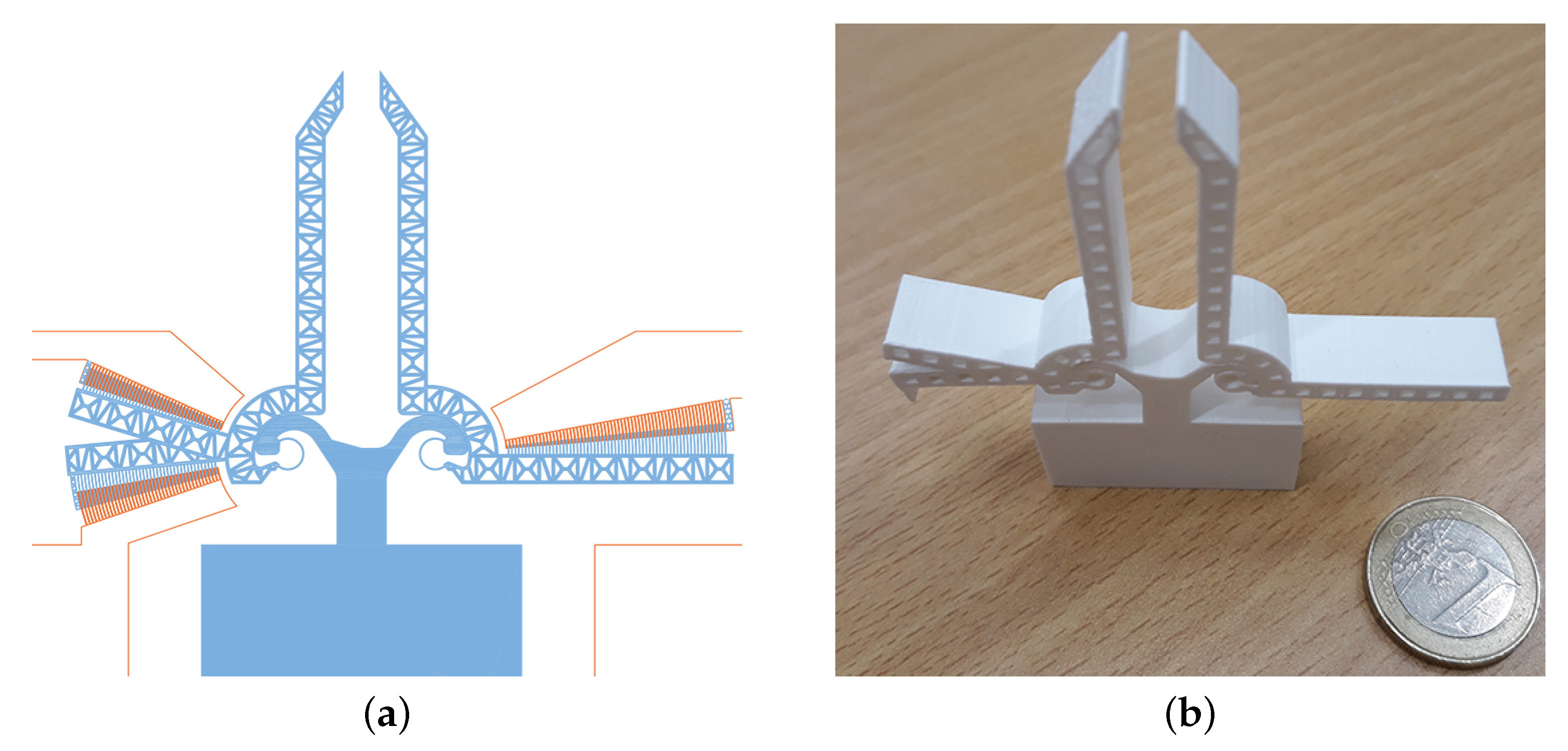
Figure 1a. This design was scaled as well as modified to fit the limits of the 3D printer accuracy to avoid unfeasible widths of fingers, gaps and curved beams. The truss structure embedded in the original links was also simplified, in order not to make critical the process of 3D printing. Finally, the fingers of the mobile comb drives were eliminated for the sake of simplicity.
The AutoCAD
dwg file was translated into the classical
stl file and then provided to the 3D printer, which yielded the layout represented in
Figure 1b.
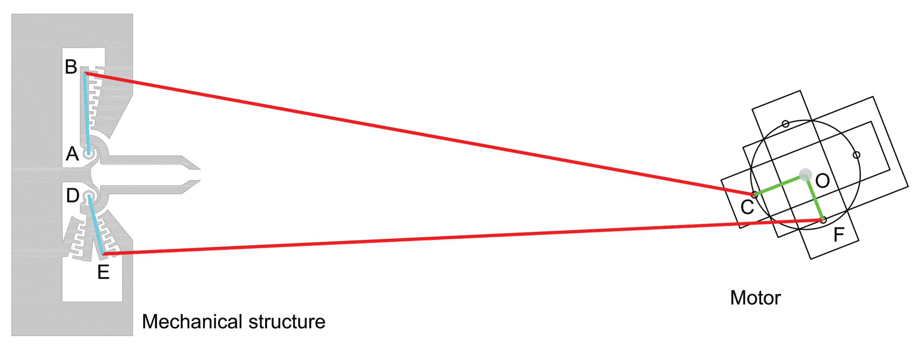
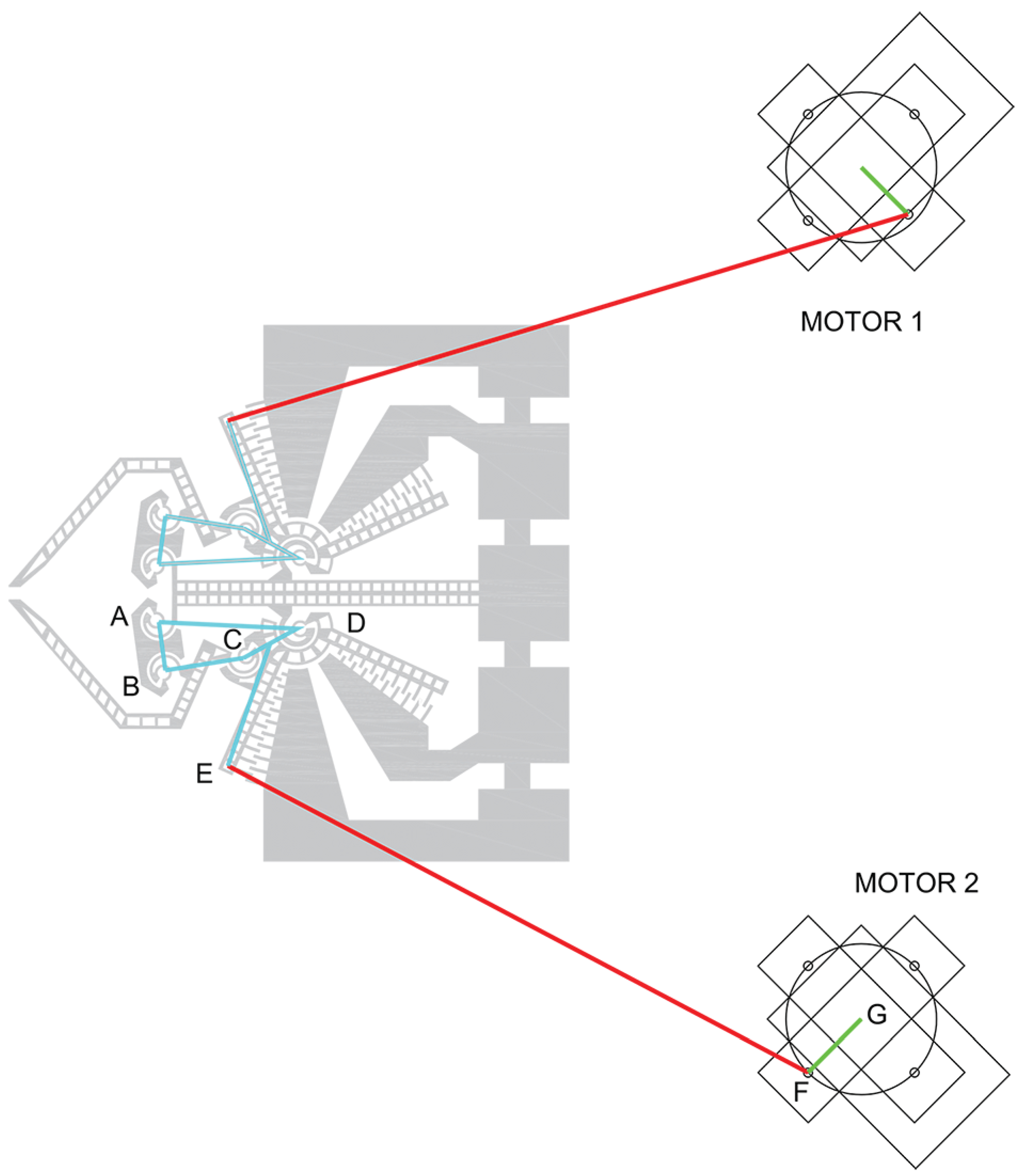
The macroscale compliant mechanisms were subject to preliminary tests which gave encouraging results in terms of mechanical properties (compliance and robustness). Then, the experimental layout was set for operational tests. Since the comb drives were not feasible at the macroscale, their action was simulated by means of cables attached to the end of the comb drive mobile wings and operated by a motor. A simplified scheme is reported in
Figure 2, where the two wings, the two cables and the two motor arms are represented, respectively, by lines AB and DE, BC and EF, and CO and FO. When the cables are under tension, the groups ABCO and DEFO can be considered as four-bar linkages, which makes it very easy to perform the kinematic analysis of the system. In the case under study, the forward run was achieved by applying a counterclockwise torque, while the return run was obtained simply by releasing the above mentioned torque, by virtue of the elastic energy stored in the flexure revolute joints A and D.
The experimental layout was completed using the same 3D printer for building the mechanical anchors and frames. The printing parameters were set by using Ultimaker Cura software
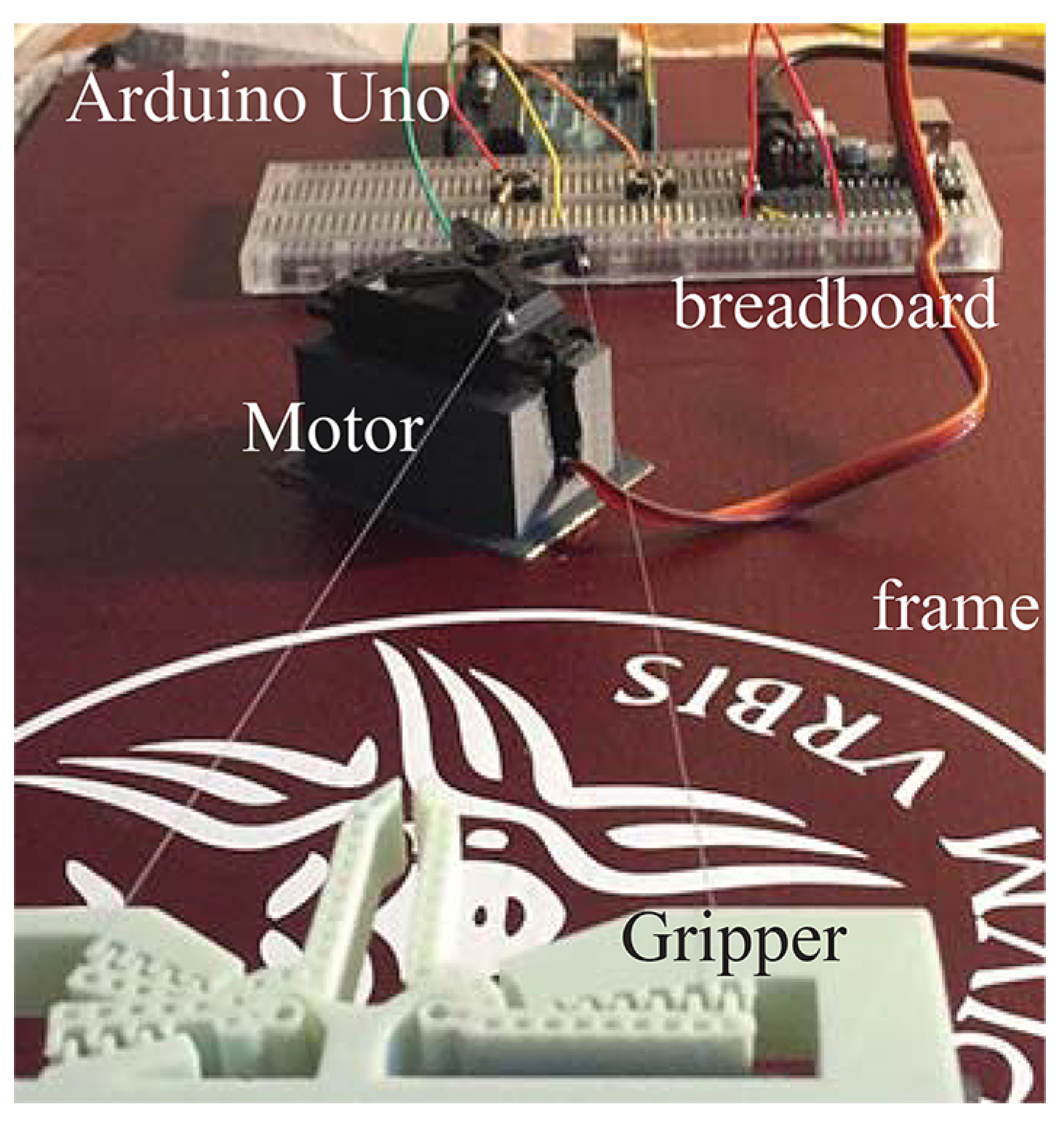
© (Version 3.2.1), and the G-code file was prepared. All components were re-printed several times and then assembled to the base. Shaking torques transmitted to the base were estimated and a proper frame was set on the motors to allow them to work adequately. Electronic circuits and control card were mounted to the same base, as a reminder that the real microsystem would be arranged on a single chip, by using ASIC (Application Specific Integrated Circuit). The arrangement is illustrated in
Figure 3.
The actual circuit was developed using Fritzing© (Version 0.9.3), and the wiring scheme was realized by using a common breadboard, which includes also connection to Arduino UNO© (REV3). As is usual for this particular microcontroller, a simple Arduino IDE© code (Version 1.8.5), was developed, tested and uploaded on the microcard, in such a way that the whole system no longer needed direct connection to the computer. Forces were transmitted to the compliant mechanisms through nylon cables. In the first configuration, the closing motion was obtained by exerting a force on the jaws levers, while the opening return motion is achieved by releasing these forces and letting the flexure elasticity to drive back the jaws to their original position.
2.3. Bidirectional Double Four-Bar Linkage Microgripper
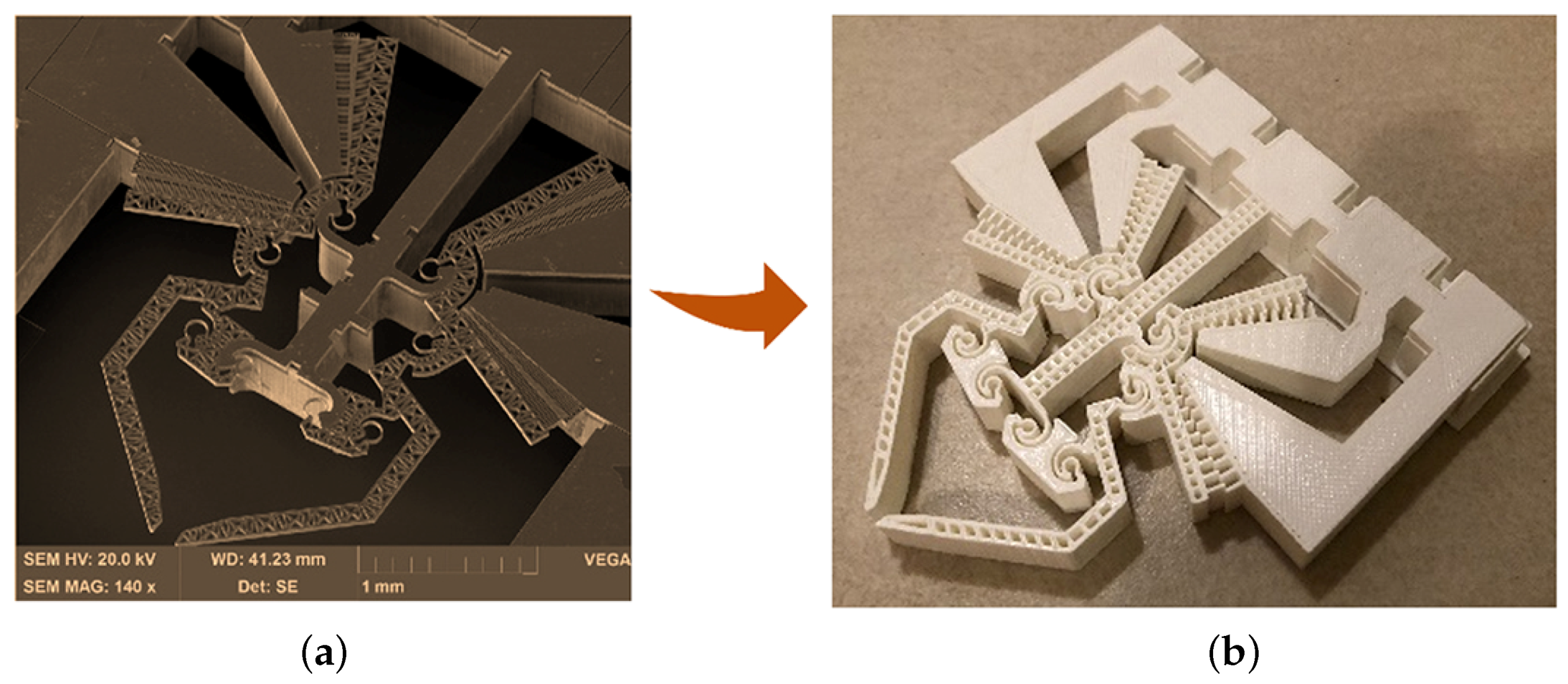
In the second project, a bidirectional microgripper, shown in
Figure 4a, was scaled up to the macroscale sample, represented in
Figure 4b, by following the same method of design, printing and actuation as described in the previous paragraph. The finger cross section was scaled from 2
m × 40
m to 0.6 mm × 1 cm, while the microgripper overall dimensions are 10.8 cm × 10.3 cm × 1 cm. The macroscale prototype was obtained in Polylactic Acid, while actuation and control was obtained by Arduino microcontroller integrated with breadboard, circuits and two rotary actuators. The comb drives were mechanically controlled by means of cables that are attached in such a way that open and close maneuvers are allowed.
The main problem with design consisted of the limited resolution of the 3D Delta printer. With the available model, the resolution was limited to 0.4 mm, thus some sections of the gripper had to be redesigned to cope with this limit. In fact, after linear scaling from the micro to the macro scale, there were still some parts (fingers and curved beams) that were too small for that resolution. Furthermore, it was also not possible to use the above-mentioned minimum size to not slow down the printing process too much, and so the minimum thickness had to be increased to 0.6 mm for both finger and gap between them. AutoCAD 2018 student version was used for mask scaling and redesigning (estimated time, non-expert user, 30 h for one person).
Ultimaker Cura© (version 3.2.1), was used for managing the printing process and changing some printer properties and maximize the likelihood of success. The main adopted changes in the printer properties were: layer height (0.1 mm), wall thickness (0.4 mm), printing temperature of the nozzle (220 C), build plate temperature (30 C) and print speed (35 mm/s), while cooling was enabled and the build plate adhesion type set to Skirt. After the printing stage, some surface grinding operations were performed to polish the surfaces (estimated time, non-expert users, 20 h for one person).
Similar to the first project, the system at the macroscale was made independent of the computer by using Arduino UNO
© capability of uploading IDE codes ready to work with the system. The actuation scheme is represented in
Figure 5. In this case, there are two motors which pull the comb drive wings to open the jaws. With reference to
Figure 5, cable FE pulls body CDE to rotate around flexure center D, in such a way that the coupler CB drives the attached jaw toward the closure position.
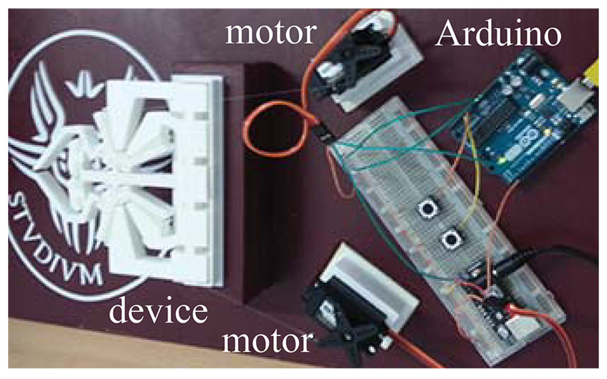
The motors were controlled by means of a circuit that is similar to that described in the previous paragraph, being composed of a breadboard, some simple electronic components and a microcontroller. A picture of the experimental set is reported in
Figure 6.
3. Results and Discussion
The projects described in the previous section are useful mainly for educational purposes. In fact, the final layout is very similar to a chip that could be used for the real microsystems. The experimental scaling was also important for the student to understand that actuation is strongly related to size. The macroscale grippers were actuated using classical electric motors, while the microgrippers were actuated by means of comb drives. Nevertheless, the projects, as a whole, were also interesting for research purposes, because they were useful to point out all the necessary operations and components.
The attempt to build a system uniformly scaled from micro- to macroscale was used to appreciate some basic and very well known concepts of actuation at the microscale. In fact, the students were encouraged to build a comb drive at the macroscale similar to the one depicted in
Figure 7a,b, which they did, of course, with no success. Therefore, the real actuation at the microscale was attempted by arming the wings of two symmetric magnetic circuits (see
Figure 8a) with conductive media and then providing magnetic fields to the base of the system to achieve motion (see
Figure 8b).
These two simple experiments stimulated the discussion concerning the effects of scaling on actuation. In particular, the students were encouraged to figure out the consequences of a uniform reduction of the geometry by a factor of 10. As known, such reduction gives rise to a reduction of the electrostatic force by 100 times, while the corresponding reduction of the curved beam rotary stiffness is 1000. Considering that the electromagnetic force is reduced 10,000 times, it is clear how electrostatic actuators perform much better than the electromagnetic at the microscale.
The benefit of these activities was not limited to the specific course, but it was also extended to more general skills, such as working in a team, rapid prototyping, actuation, control and mechanical design. In particular, the students had to solve specific problems that are of a certain interest today.
The first problem was the optimal setting of the 3D printing system parameters, by taking into account some specific properties such as the nozzle section (0.4 mm) and the material (Polylactic acid, PLA). Then, the operational parameters had to be considered, such as the printing temperature (210–215 C), and speed. Furthermore, different actuation strategies were analyzed and compared. After exclusion of comb drives, for losing efficacy after dimensional scaling, the servomotors power supply was originally arranged directly from one Arduino 5 V pin. This solution gave rise to several problems, such as torque ripples, unstable position and overheating due to excessive current. Therefore, the classical external power supply scheme with grounding GND pin has been arranged for both the motors, while Arduino provided control. Finally, safety principles have been also implemented during the activities, especially by means of personal protective equipment (PPE).
4. Conclusions
This paper has shown a way to improve the teaching activities in the field of microsystems and micro-manipulation. The investigation has proven how the complex teaching–learning process may be improved by tuning lab activities to the specific students’ characteristics, expressed in terms of multiple intelligence inventory, interest, and motivation. The investigation has also proven that the use of low-cost, tinkering approach boosts the student involvement up to a level of interdisciplinary knowledge which was good enough for them to build a system complete with mechanical structure, transmission, actuation, and control. Students declared their satisfaction and excitement during the project, while the final exams showed that their understanding of phenomena at the microscale improved much after the tactile activities at the macroscale. The authors hope that the two papers will be somehow useful to professors for employing new methods of interactive and dedicated teaching for their laboratory courses.
