1. Introduction
Soft robotics technology has drawn great research interest over the past two decades for its relatively low cost, safe human–robot interaction and application in confined or constricted environments (see e.g., [
1,
2,
3,
4,
5,
6]). Dielectric elastomer actuators (DEAs) are an emerging type of soft actuator that has advantages over conventional actuators in terms of large actuation strains, high energy density, good scalability and low cost [
7]. Many applications along with different configurations of DEAs have been developed. For example, DEA-driven robots [
8,
9,
10,
11]; fast and accurate tunable optics [
12,
13]; and miniature DEA pump and valves [
14,
15].
Among all the DEA configurations, the conical configuration has been widely adopted in soft actuation applications for its capability of antagonistic actuation [
16]; multi-degree-of-freedom (DoF) operation [
17]; crawling locomotion [
11]; and flapping robots [
18]. A conical DEA consists of a piece of elastomer membrane bonded to a rigid circular ring with a disk in the centre. A biasing mechanism produces a protrusion force that pushes the central disk out of plane to form a conical geometry.
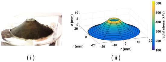
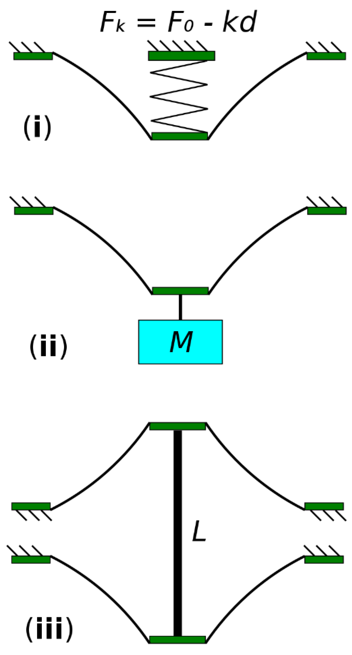
Figure 1 shows a conical DEA with different out-of-plane deformation, where it can be seen that as the protrusion force increases, the out-of-plane deformation of the conical DEA also increases. Common biasing mechanisms are a linear compression spring, a biasing mass and an antagonistic membrane, as shown in
Figure 2, respectively.
In this work, we demonstrate how the performance of a conical DEA can be optimized in terms of its stroke and mechanical work output relative to its size. We will focus on the analysis of conical DEAs with the following three bias elements: a linear compression spring, a biasing mass and an antagonistic conical membrane with the same pre-stretch which creates a double-cone DEA. A conical DEA with a biasing mass has been shown to be able to generate a larger stroke compared to the one with a linear compression spring [
19]. However, the biasing mass increases the overall size and weight of the actuator, and the principle of utilizing gravity restricts its application. On the contrary, a conical DEA with a linear compression spring has a compact size and is not restricted by gravity. For antagonistic double-cone DEA configuration, both conical membranes can be actuated separately to achieve bidirectional actuation, as has been shown by [
17,
20]. Despite the fact that using a bi-stable mechanism can potentially achieve a larger stroke compared to the three biasing elements aforementioned [
19,
21], the performance of the DEA is subjective to the specific design of the bi-stable mechanism, which makes it extremely challenging to generalize this biasing element and perform optimization, and hence it will not be studied in this work.
Several examples of prior work have been done to characterize the conical DEA performance. Approximated mathematical models have been developed to characterize the performance of conical DEAs with biasing springs and biasing mass [
22,
23,
24]. Two important simplifying assumptions are made in their models, which include a truncated cone-shape approximation and homogeneous stress distribution on the deformed DEA membrane. Based on these modelling works, the effects of geometry and size on the performance of a conical DEA with a biasing mass was investigated in [
25]. However, due to the lack of sufficient experimental samples, no optimization and in-depth analysis have been conducted. As has been pointed out by [
24,
25], the simplifying assumption of a truncated cone shape becomes less valid when the ratio of the inner disk radius to outer ring radius,
a/
b, becomes smaller, which leads to a greater error in model prediction. A quasi-static analytical model for conical DEA which is based on thermodynamic equilibrium and geometry relationships was developed in [
26]. This model is capable of capturing the nontruncated membrane shape and the inhomogeneous stress distribution. The viscoelastic behaviour of a conical DEA has been investigated in [
27,
28] by including time-dependent viscosity into this analytical model, however, it was not validated by experiments. The model was shown to be capable of predicting the quasi-static performance of a conical DEA made with VHB 4910 and hydrogel electrodes [
29]. The effect of the radius ratio
a/
b and pre-stretch ratio to the energy of conversion of a conical DEA was investigated in [
30] by using VHB 4905, but no comparison has been made on the effect of the biasing elements.
In the following sections, we first present a modified analytical model adopted from [
26] which can characterize the quasi-static force–displacement relationship of a conical DEA at an applied voltage. We then present experiments to verify this model and identify the model parameters. Based on the model, we present the optimization in terms of both stroke and mechanical work output by varying the actuator geometry and pre-stretch ratio for three cases: (I) single-cone DEA with a linear biasing spring; (II) single-cone DEA with a biasing mass and (III) antagonistic double-cone DEA.
2. Quasi-Static Analytical Model
In this section, we briefly describe the analytical model of the conical DEA, and a detailed description of this model can be found in the
supplementary material. In its initial state, the elastomer membrane has an initial thickness
T and is stress and constraint free. The membrane is pre-stretched biaxially by a stretch ratio of
λp. The pre-stretched membrane is then bonded to a rigid ring of radius
b and a disk of radius
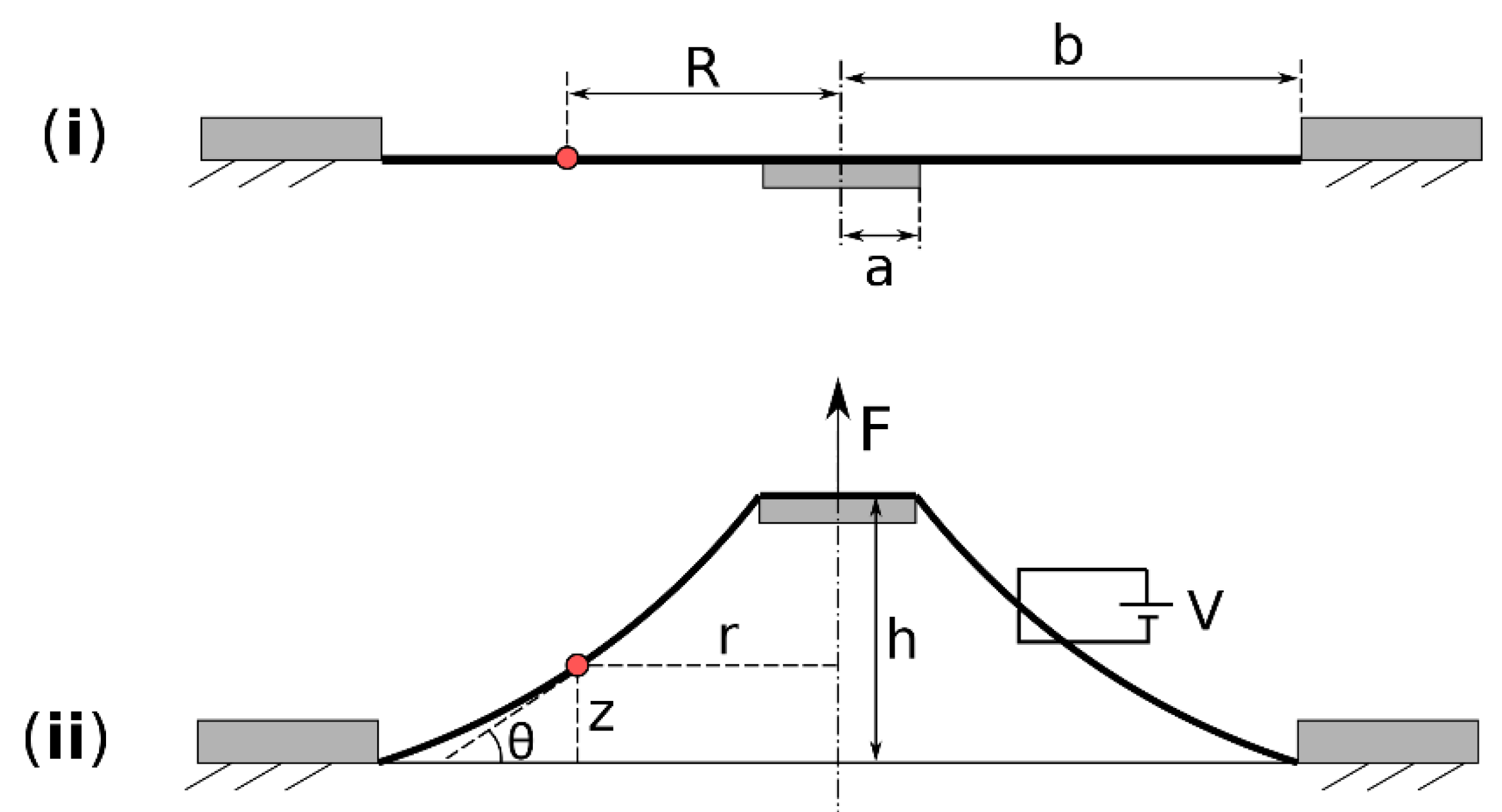
a, as illustrated in
Figure 3i. Both sides of the membrane are coated with compliant electrodes. An external force
F and a voltage
V are applied which move the membrane out of plane by a distance
h and cause it to form a conical structure, as shown in
Figure 3ii. After the out-of-plane deformation, a particle on the membrane at radius
R in
Figure 3i now occupies the position of (
r(
R),
z(
R)), where
r is the current radius and
z is the distance to the undeformed plane. The coordinates of (
r,
z) for
R = [
a,
b] describe the geometry of the conical DEA shape, and are developed as follows (after [
26]).
The coordinates of (
r,
z) are expressed as follows:
where
is the radial stretch due to the out-of-plane deformation and
θ is the angle between membrane tangent and horizontal plane at point (
r,
z) and is described as
where
s1 and
s2 are the nominal radial and circumferential stress. The external force
F and membrane reaction force are equal in quasi-static state, and this relationship is expressed as
where
σ1 is the radial stress at point (
r,
z), and
λ1 and
λ2 are the total radial and circumferential stretches, respectively, and are given as
To describe the free energy density
W as well as
s1 and
s2, the Ogden model [
31] was adopted in this work, which is given as
where
μ and
α are material parameters,
N is the number of terms in this model,
is the relative dielectric constant of the material and
is the permittivity of vacuum.
Then, the state of the conical DEA can be solved by three differential Equations (1)–(3) and an algebraic Equation (4), together with boundary conditions
The model is numerically solved in Matlab (Mathworks) using shooting method and the 2018ode15’ function.
4. Stress and Electrical Field Analysis of a Conical DEA
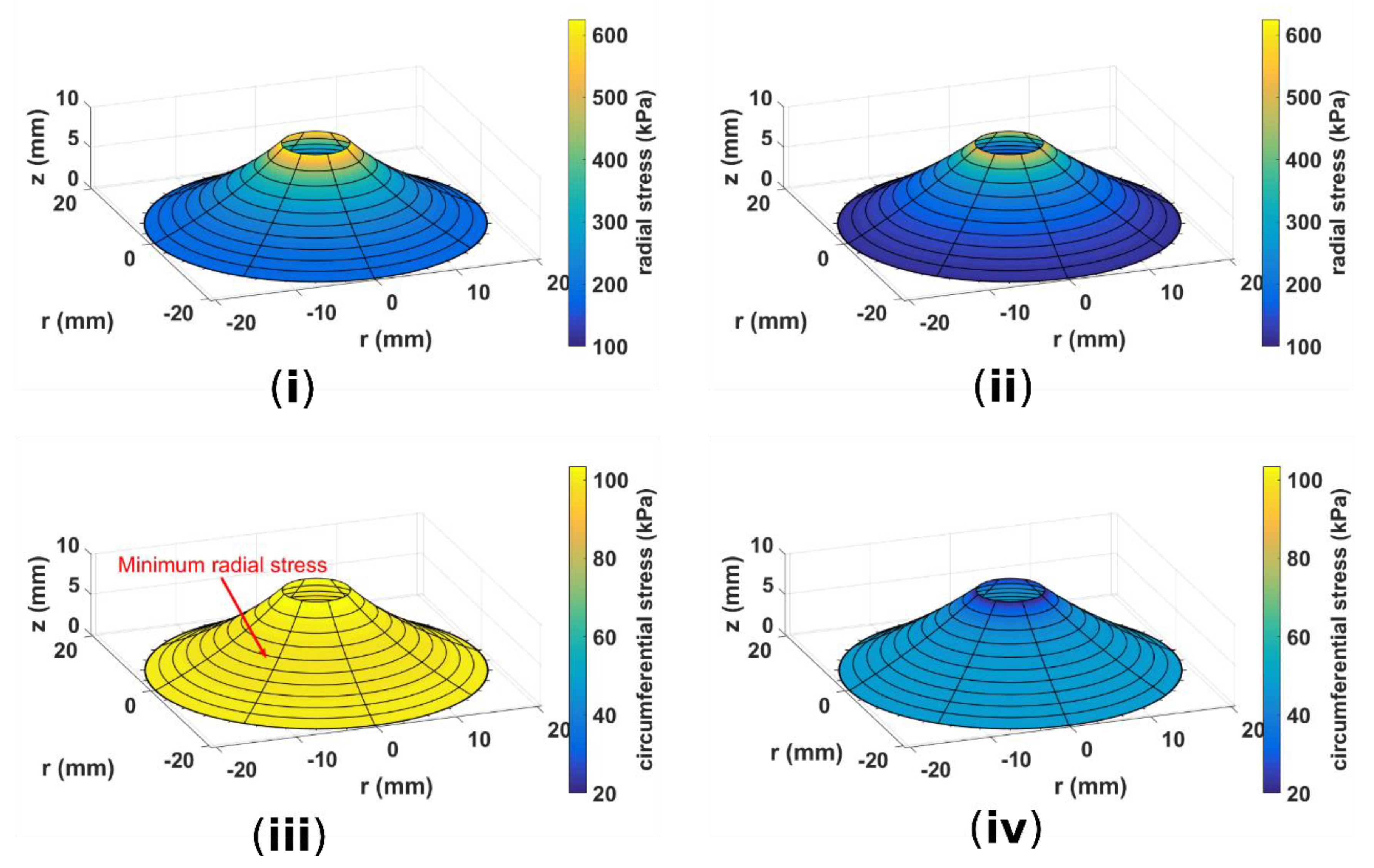
Owing to its complex three-dimentional geometry and boundary conditions, the strain–stress distribution on a conical DEA is very inhomogeneous. In this section, we attempt to reconstruct the stress distribution along the DEA using the analytical model. Here we set
b = 20 mm,
a = 4 mm,
h = 10 mm and
λp = 1.2 × 1.2.
Figure 5 compares the radial and circumferential stress
and
when
V = 0 and
V = 1.5 kV. When a voltage is applied to the DEA, a clear reduction in both radial and circumferential stresses can be observed and the DEA is closer to a truncated conical shape. The lowest circumferential stress is near the edge with the central disk. If the voltage increases further, the circumferential stress near the inner edge will become negative first, which results in a wrinkled membrane in this region.
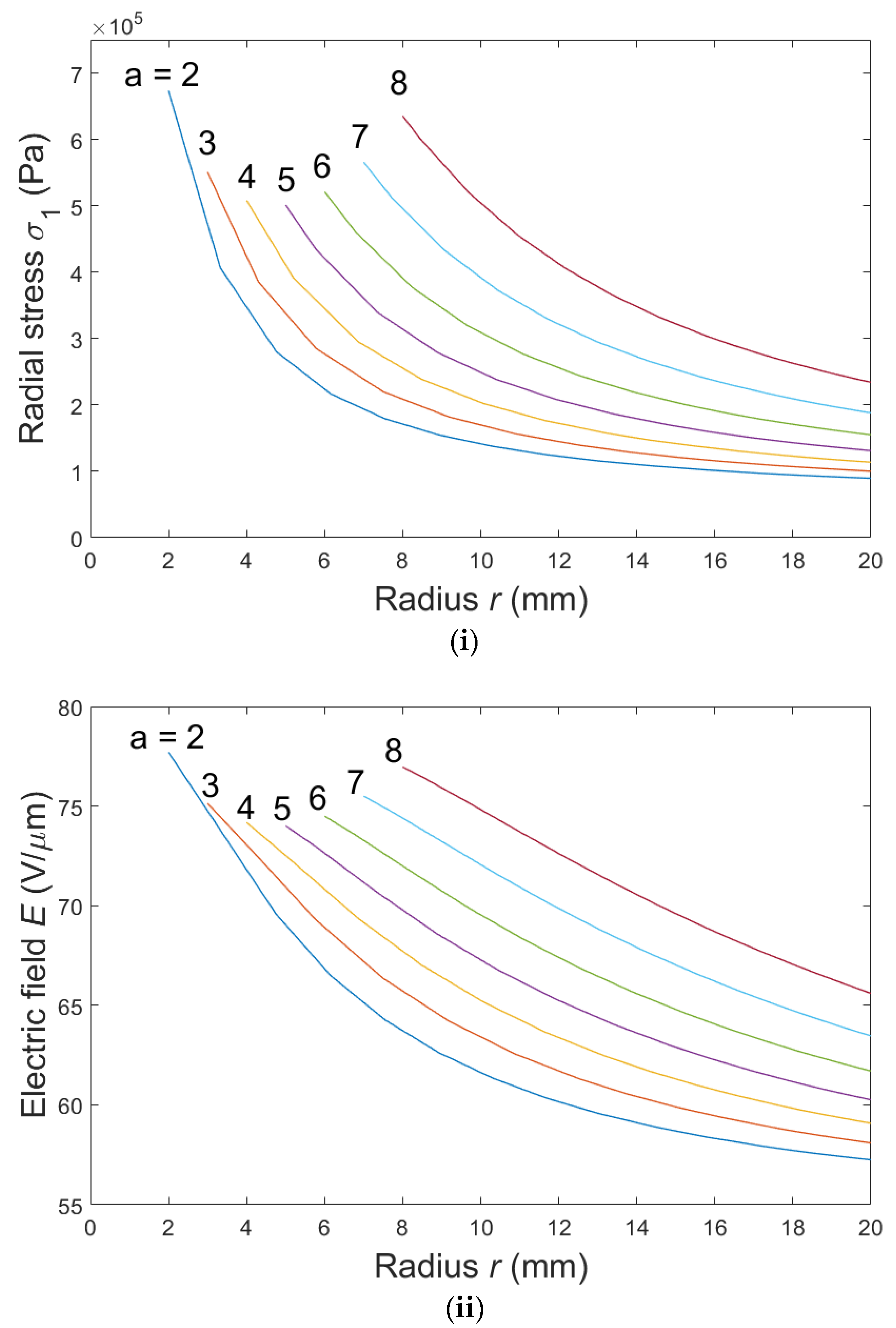
We investigated the effect of the
a/
b ratio on the radial stress and electric field distrubtion on the conical DEA membrane. Here we vary the
a/
b ratio by changing
a from 2 mm to 8 mm while keeping
b constant at 20 mm, which account for
a/
b ratios of 1/10 to 2/5. The out-of-plane deformation
h is fixed at 10 mm and a voltage of
V = 1.5 kV is applied to the DEA.
Figure 6i plots the radial stress
σ1 along the DEA membrane for different
a values. For each DEA, the radial stress is highest near the boundary with the central disk (
r =
a) and reduces as
r increases. The DEA with
a = 2 mm has the largest peak radial stress and the steepest stress gradient among all samples, which suggests it has the most inhomogeneous radial stress distribution on the membrane. Note that the peak radial stress reduces first then increases again as
a increases.
Figure 6ii shows the electric field along the membranes of these DEA samples. The same trends found in the radial stress study can be noticed here. The peak electric field occurs near the central disk, which suggests that dielectic breakdown is more likely to happen near the inner edge, and the DEA with the smallest
a/
b ratio has the largest electric field peak and also the steepest electric field gradient. Peak electric field also reduces first and increases as
a increases. The results suggest that a disk radius of
a = 5 mm, which accounts for an
a/
b ratio of 1/4, results in the most homogeneous stress and electric field distribution along the membrane. Intuitively, a more homogeneous stress distribution will simplify actuator control as the applied electric field can more easily be maintained within the dielectric breakdown limit.
5. Stroke and Work Output Optimization
To optimize the conical DEA, the characteristic DEA geometry, determined by the central disk-to-outer-ring radius ratio
a/
b, and the pre-stretch ratio, have to be tuned. Three conical DEA configurations are considered: (I) biasing spring; (II) biasing mass; (III) antagonistic conical DEA. For each case, configuration-specific parameters can also affect its performance. In order to avoid overcomplicating the optimization with too many variables, in the following studies we choose to vary the general parameters that affect all three cases, which are the radius ratio
a/
b and pre-stretch ratio while leaving all configuration-specific parameters for each case fixed throughout the study. We keep the outer ring radius
b constant at 20 mm while varying
a from 2 mm to 10 mm (resulting in
a/
b from 1/10 to 1/2) with an increment of 1 mm and pre-stretch ratio from 1 to 1.3 with an increment of 0.1.
Table 1 shows the configuration-specific parameters used in this optimization. The stroke
d generated by a DEA is related to the electric field applied to it, and to have a larger stroke, a higher electric field is desirable. As a result, the main criteria of this cone DEA optimization is to achieve the highest electric field on the membrane within the dielectric breakdown limit of 80 V/μm as reported by the manufacturer [
33]. To prevent mechanical failure, the total strain of the membrane shall not exceed 2.4 × 2.4. As shown in
Figure 6, the highest stress (strain) and electric field occur near the edge of the central disk, hence in optimization, attention is paid to the electric field and strain near this boundary region. The detailed optimization process and the discussion regarding optimization variables and parameter selection are given in the
supplementary material.
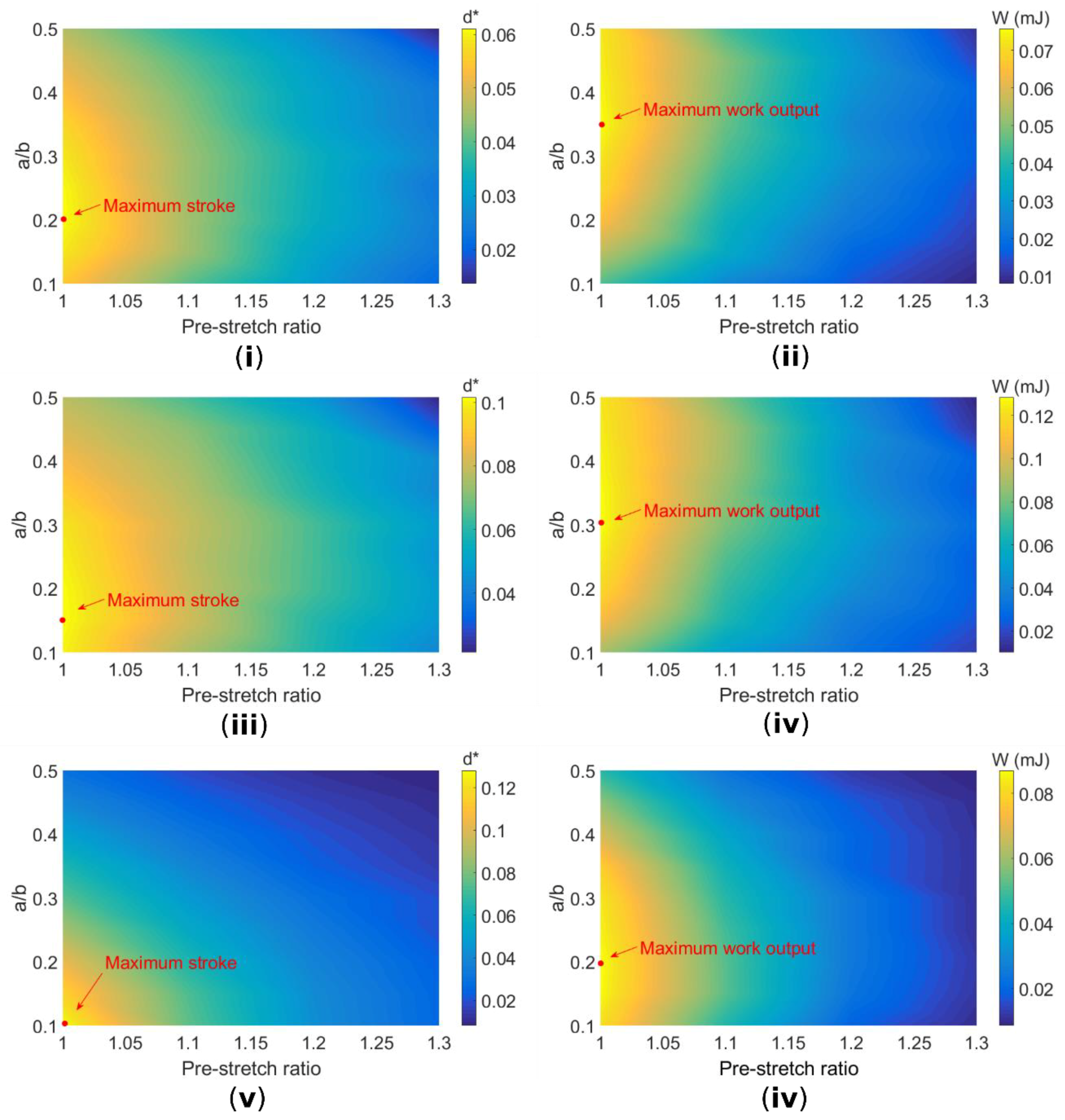
The optimized stroke and work output
W as a function of pre-stretch and radius ratio
a/
b for three cases are given in
Figure 7. The stroke output has been normalized to describe the absolute stroke of the DEA
d relative to the radius of its outer ring
b,
d* =
d/
b. In this study, the maximum stroke is mainly affected by the dielectric breakdown failure mode and no mechanical failure occurs.
For all three cases, the maximum stroke and work output are obtained for a pre-stretch ratio of
λp = 1 × 1, which suggests that for the use of this specific Parker elastomer in conical DEA applications, no pre-stretch is required in order to achieve a good performance. Indeed, the out-of-plane deformation introduces radial stretch, which can be sufficient for this specific silicone elastomer. However, it should be noted that pre-stretch has been shown to increase the dielectric strength [
34], while in this study, a constant dielectric strength has been adopted. The effect of pre-stretch on dielectric strength and hence the maximum stroke and work output requires further investigation in the future work.
Maximum stroke and work output are achieved for different a/b ratios. A general trend for all three cases is stroke maximization is obtained for a lower a/b ratio while a larger a/b ratio is required to maximize work output. This could be due to the fact that a conical geometry with a larger a/b ratio leads to a larger angle θ between the out-of-plane membrane and the central disk (see Equation (4)), which results in a larger force output hence work output despite the stroke being slightly lower than the DEA with a smaller a/b ratio.
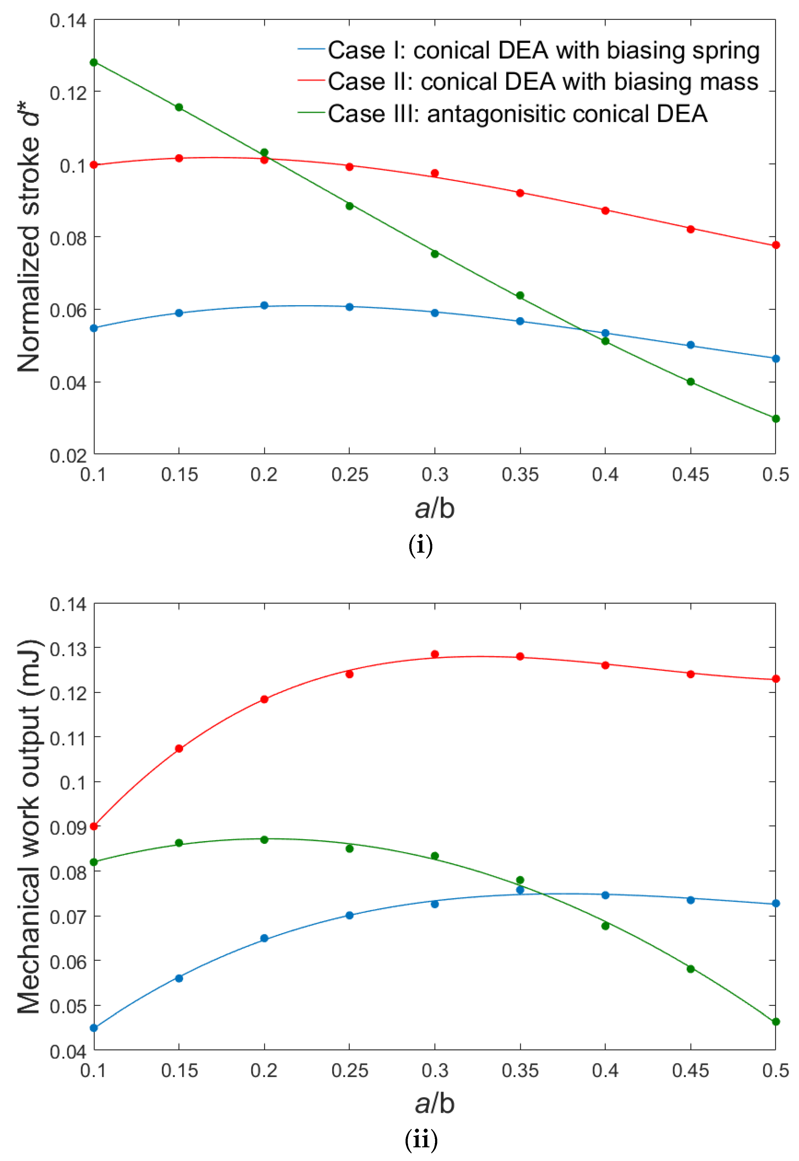
Figure 8i,ii compares the maximum stroke and work output at pre-stretch ratio of
λp = 1 × 1, respectively. Case III produces the maximum normalized stroke of 0.128 at the lowest
a/
b ratio of 0.1 and its stroke decreases approximately linearly as the
a/
b ratio increases, while cases I and II have their peaks at
a/
b = 0.15 and 0.2, respectively. Case I has the lowest stroke of 0.061 among all three. The reason why the normalized stroke in case III decreases with the increasing
a/
b ratio is likely due to the nonlinear force–displacement relationship of the biasing element (antagonist cone DEA). In terms of work output, case II produces a much higher work output of 0.129 mJ at
a/
b = 0.3 compared to the other two cases (0.076 mJ at
a/
b = 0.35 for case I and 0.087 mJ at
a/
b = 0.2 for case III). The highest work output in case II (biasing mass) can be explained by the fact that when a conical DEA is actuated, the force output of a conical DEA with biasing mass will be higher than that of the biasing spring and antagonist cone DEA (the force exerted by both linear spring and antagonist cone DEA will reduce while a biasing mass will maintain a constant force throughout the actuation). Hence the maximum work output that can be produced by the actuator, which is the integral of force output over stroke, could be higher than conical DEAs with biasing spring and antagonist DEA. It should be noted that for the double-cone configuration, only one cone membrane has been activated in this study while the antagonistic cone membrane remained passive. If the antagonistic cone can also be activated, the overall stroke of the double cone should be 0.256 with a maximal work output of 0.174 mJ. For all three cases, the peak stroke and work output occurs at a relatively low
a/
b ratio, which suggests that a low
a/
b ratio geometry, or more specifically,
a/
b between 0.1 and 0.35, are possibly the best for all three conical DEA configurations. A smaller
a/
b ratio may lead to a puncture on the membrane and a too large
a/
b ratio will limit the performance of a conical DEA. Also, an
a/
b ratio within this range results in more homogeneous stress and electric field on the membrane, as illustrated in
Figure 6ii, which arguably can improve the lifespan of the actuator. This also could be the reason why the optimal
a/
b ratios for work output in all three cases lie in the region; as the electric field becomes more homogeneous, the electric field on a larger percentage of the DEA membrane can approach its breakdown limit, which results in a higher electrical input and hence higher mechanical work output. Note that the selection of the specific parameters for the biasing elements in all three cases are empirical, hence the peak stroke and work output presented in this work do not necessarily represent the best performing conical DEA of each configuration. However, we believe this work can still serve as a guideline for any specific conical DEA design.
6. Conclusions
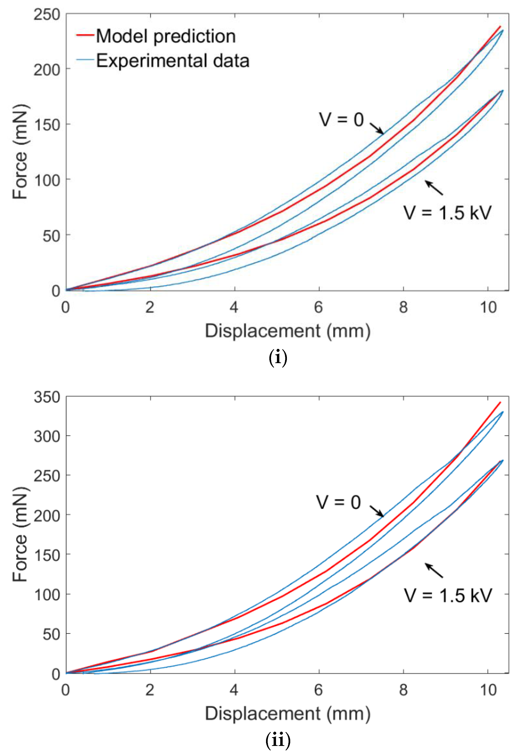
In this work, a quasi-static analytical model is presented for a conical DEA configuration which captures its inhomogeneous strain and stress distribution. This model is then verified against experiments and excellent agreement between the model prediction and experimental data is shown. By using simulation, we reconstruct the three-dimensional geometry of the conical DEA and illustrate that the radial and circumferential stresses are very inhomogeneous, which indicates that the simplifying assumption of homogeneous stress in the previous conical DEA studies can lead to significant errors. Based on this inhomogeneous distribution on the membrane, the occurrence of electric breakdown and wrinkling are believed to be more likely to happen near the boundary between DEA membrane and central disk.
Optimization is performed with this analysis for the three common conical DEA configurations. The optimization is characterized by the normalized stroke and work output and is performed by varying the geometry a/b ratio and pre-stretch. The results show that (a) for all three configurations, normalized stroke and work output are maximum for a pre-stretch ratio of 1 × 1 for the Parker silicone elastomer, which suggests the stretch caused by out-of-plane deformation is sufficient for this specific elastomer. (b) For all three configurations, maximum stroke and work output are achieved for different a/b ratios. A general trend for all three cases is that stroke maximization is obtained for a lower a/b ratio, while a larger a/b ratio is required to maximize work output, but the optimal a/b ratio is less than 0.3 in all three cases. (c) Double-cone configuration has the largest stroke while single cone with a biasing mass has the highest work output.
In conclusion, this work presents a novel design guideline for conical DEAs. Based on the specific requirements of applications, optimal conical configuration with tuned geometry and pre-stretch can be selected.


