Article

Modelling and Operator-Based Nonlinear Control for a Miniature Pneumatic Bending Rubber Actuator Considering Bellows

1
Department of Electrical and Electronic Engineering, Graduate School of Engineering, Tokyo University of Agriculture and Technology, 2-24-16 Nakacho, Koganei-shi, Tokyo 184-8588, Japan
2
Graduate School of Natural Science and Technology, Okayama University, 3-1-1 Tsushima-naka, Kita-ku, Okayama 700-8530, Japan
*
Author to whom correspondence should be addressed.
Actuators 2018, 7(2), 26; https://doi.org/10.3390/act7020026
Submission received: 12 April 2018 / Revised: 29 May 2018 / Accepted: 31 May 2018 / Published: 2 June 2018

Abstract

:
Recently, many kinds of soft actuators composed of flexible materials, such as silicon rubber, have been studied in the mechatronics field with increasing attention on the artificial muscle in welfare, medical care and biotechnology. Particularly, pneumatic-driven soft actuator moves flexibly and works safely because of not electrical but pneumatic input, so that the actuator could perform effectively in the medical operations. A miniature pneumatic bending rubber actuator is a tiny pneumatic-driven soft actuator which has some chambers connected to only one tube providing compressed air and the chamber has bellows. This actuator can bend circularly in two directions and grab delicate objects such as fish eggs, by inputting pressure into its chambers. The actuator, however, has nonlinear property derived from elastomer in input-output relation. The actuator, therefore, sacrifices some degree of control performance instead of obtaining the passive flexibility to delicate objects. To solve the above problem, previous studies have shown, by the experiments, that the effectiveness of designing the nonlinear feedback control system using robust right coprime factorization based on the operator theory for control of the output angle of the actuator. However, the mathematical model used for designing the system caused modelling error because the bellows were not considered in deriving the model. The mathematical model should fit experimental value as well as possible for system design and there has been no example modelling of the micro hand having bellows. In this research, a new model of the micro hand considering its bellows with elastomer property is proposed. Moreover, a control system using the robust right coprime factorization based on the operator theory is designed for the new model. Finally, the effectiveness is shown in the experiment.

1. Introduction

A soft actuator is expected to be available in medical, welfare, and biotechnology because its elastic compliance makes the contact harmless with fragile objects. The actuator is driven by pressurized air. It has some pressure chambers composed of flexible material, such as silicon rubber; it takes advantages of elastic inflation by inputting pressure. In the welfare field, McKibben artificial muscle, which is applied in a rehabilitation tool, is one of the soft actuators. In the medical and biotechnological field, ionic polymer-metalcomposite actuator [1] was invented and has been studied on control method for it. Moreover, a flexible micro actuator (FMA) was also invented, expected safe and flexible operation, and has been studied on its safe and refined control recently [2]. FMA has three pressure chambers disposed in parallel and closely to each other in rubber tube. It is made of fiber-reinforced rubber, which helps each chamber to stretch in the long axial direction. This actuator, therefore, operates with three degrees of freedom. However, it is difficult to minimize the scale for realizing the operation in more narrow environments because the structure for the elastic inflation complicates the minimizing process: three chambers and three providing tubes connected to each chamber.
A miniature pneumatic bending rubber actuator is developed to solve the above problem [3]. The actuator has only one cylindrical chamber, and thus, has one tube. Its round surface is shaped into bellows. Its cylindrical shape and bellows make the actuator bend dynamically at less pressure [4]. These structures also simplify the process for minimizing [5]. The actuator, however, has complicated property in input-output relation including air compressibility and rubber nonlinearlity, so that it is difficult to use the classical control theory. For the stable control of the actuator, a control system has been proposed, designed using robust right coprime factorization based on operator theory [6,7,8,9,10,11]. A model for the system was then devised [12]. This modelling scheme applied the theory of modelling the pneumatic soft actuator using fiber reinforced rubber [13]. This model, however, included modelling error caused by not considering bellows. The modelling error affects control performance in delicate operation; nevertheless, there has been no example of modelling the actuator considering its bellows and elastic property.
This paper proposes a new model of the actuator considering its property. This new model represents a relation between input pressure and bending angle. The model is derived from statics and neo-Hookean elasticiy [14,15]. In addition, a nonlinear control feedback system for the actuator is designed by using the operator theory. Finally, the effectiveness is verified by tracking control experiment.

2. Materials and Methods

This section describes the methods to control the motion of the miniature pneumatic bending rubber actuator. First, a new model was derived from balance of moments working on bellows by applying neo-Hookean law, which gives strain-stress property of a single-strand rubber. The strain-stress property helps modelling include nonlinear elastricity of the actuator more exactly than that by the Hooke’s law. The feedback control system was then designed based on operator theory, using the new model. The design guideline is given by robust right coprime factorization [6] to stabilize unstable elements in the plant. Completing the design was made by simulation using MATLAB (R2013a), which is one of the effective software products for system engineering. Finally, an experiment for tracking performance was conducted to verify the effectiveness of the proposed system. Each subsection below shows detailed information about the structure of the actuator, the modelling and the system design.

2.1. The Structure of the Miniature Pneumatic Bending Rubber Actuator

The miniature pneumatic bending rubber actuator. The actuator bends with its bellows outside at positive pressure (at +60 kPa in Figure 1) and with these inside at negative pressure (at −20 kPa in Figure 1). The actuator has an inextensible flat side and an extensible bellows side which consists of pressurization chambers and fine channel. If positive pressure is input into the actuator, the pressurized gas expands the chambers from the inside through the channel, and the bellows side then inflates preferentially and, if there is negative pressure, deflates. The actuator, therefore, bends from a linear rod into an approximate circle by difference in deformation between the extensible and inextensible side. Moreover, the bellows design enables faster and lower-powered actuation than no modification [4]. Duration for repetitive use can be also prolonged because the bellows deformation dominantly contributes the entire actuation to reduce load to rubber durability.

2.2. Modelling

2.2.1. Neo-Hookean Model

Neo-Hookean model [14,15] represents a relation between strain ε and stress σ in single-strand rubber as
σ = E 3 1 + ε 1 ( 1 + ε ) 2
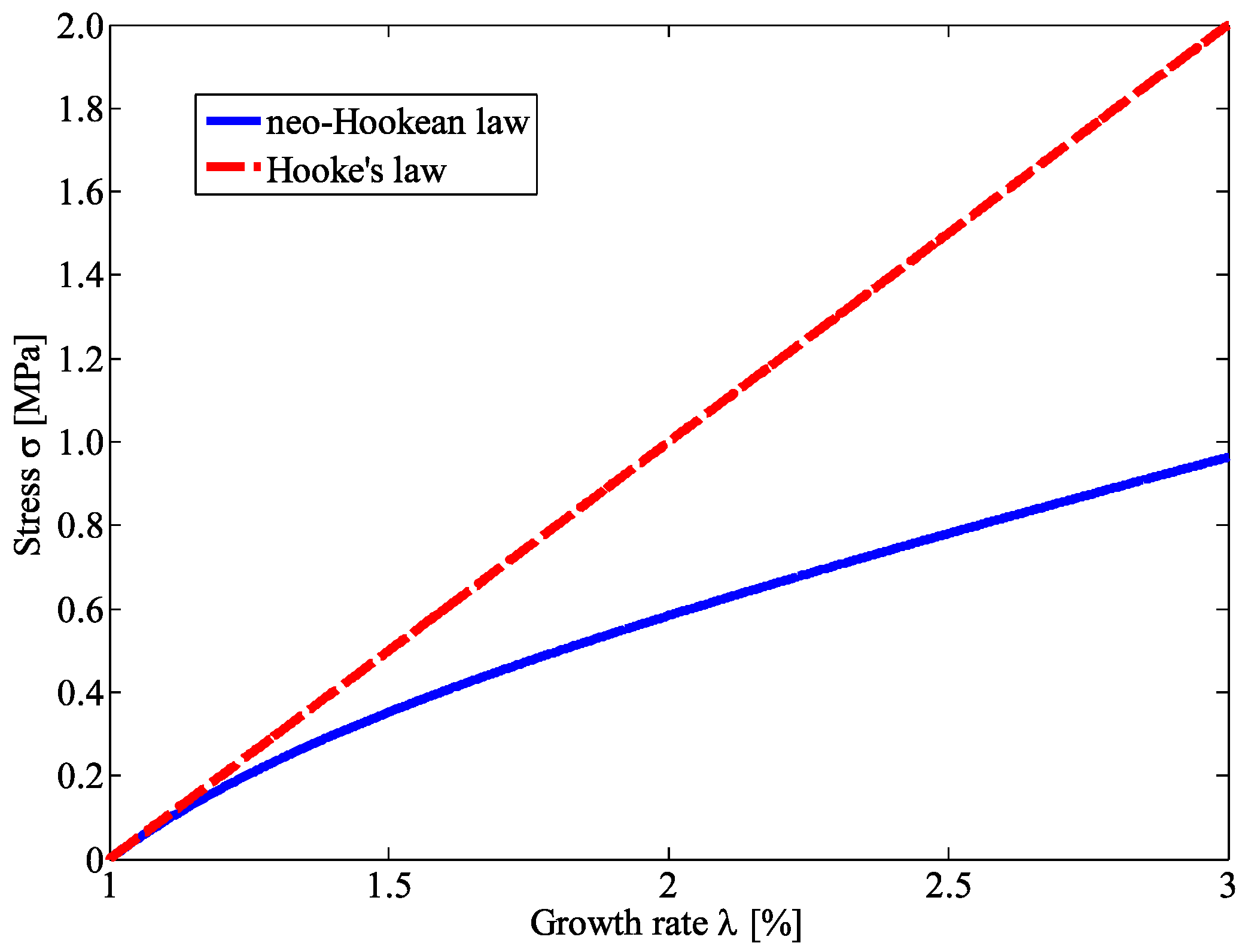
Figure 2 compares two properties by tensile simulation of single-strand rubber; the neo-Hookean model and Hooke’s model represented as σ = E ϵ , then assuming E = 1 for the sake of brevity. Figure 2 indicates that the neo-Hookean model is more flexible than Hooke’s model for the same stress, so that the neo-Hookean law is better choice for modelling the rubber actuator. This paper makes the new model assuming that the neo-Hookean model should fit the property of the material (KE1603A/B; ShinEtsu Silicones, Akron, OH, USA) used in the actuator.

2.2.2. Relation between Input Pressure and Output Angle

The new model is formulated focusing on the relation of input pressure p ( kPa ) and output angle θ ( rad ) in Figure 3a, where L ( m ) is initial length and l ( m ) is partial length, and Δ L ( m ) represents deformation length of the actuator. Figure 3 shows forces working on bellow unit; f 1 ( N ) , f 2 ( N ) , and f p ( N ) . f 1 and f 2 are elastomeric forces on a chamber and a channel respectively.
f p is surface force caused by pressure. The bellow unit itself bend at an angle Δ θ ( rad ) when internal pressure is kept constant. At every point on the end surface, these three forces then satisfy
f 1 = f 2 + f p
The Δ θ should be included in the theoretical formulae of two forces f 1 and f 2 because the angle Δ θ is regarded as strain causing the stresses. The replacement between Δ θ and strain ε 1 to chamber, or ε 2 to channel is represented as:
ε 1 = R 1 Δ θ 2 l ,
ε 2 = R 2 Δ θ 2 l
These equations were derived based on Figure 3c. Compared with the inside of the actuator, the outside strains depending on Δ θ / 2 . f 1 and f 2 were derived with strain ε 1 , ε 2 based on neo-Hookean law as:
f 1 = E 3 1 + ε 1 sin ϕ 1 ( 1 + ε 1 sin ϕ ) 2 R 1 t d ϕ ,
f 2 = E 3 1 + ε 2 sin ϕ 1 ( 1 + ε 2 sin ϕ ) 2 R 2 t d ϕ
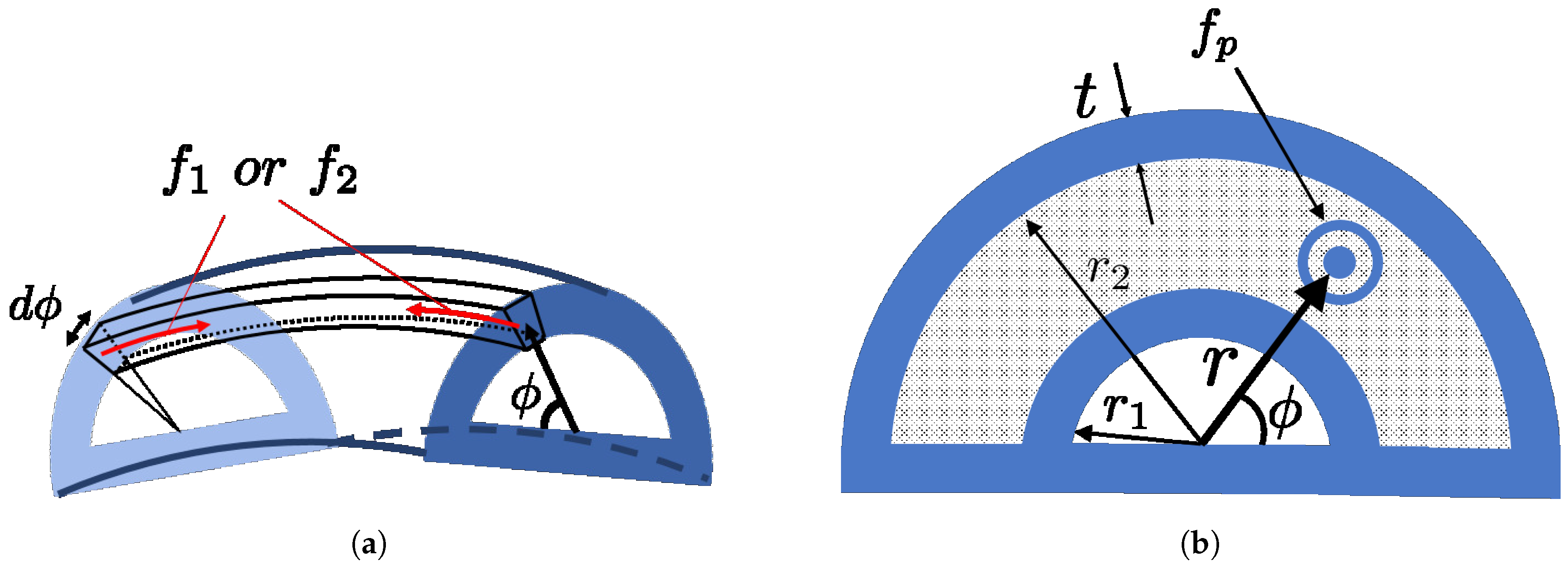
where R 1 is representative radius of chamber, R 2 is so of channel and E is Young’s modulus of the rubber. These equations mean that f 1 and f 2 are caused by strain of line elements in Figure 4a. Each ε is replaced with ε sin ϕ assuming that the strain depends on height sin ϕ from the flat side: for example, ε sin ϕ yields the maximum ε at ϕ = π / 2 and the minimum 0 at ϕ = 0 . f p works on the hatched area in Figure 4b is derived as
f p = p r d r d ϕ ,
where, in Figure 4b, r ( m ) is distance of working point from the center on the semicircle, t ( m ) is thickness of elastomer, and d ϕ ( rad ) is the angle from flat end. Equation (7) is explained as f p is yielded by multiplying the pressure p and a micro area r d r d ϕ . ϕ and r range for 0 ϕ π and r 1 + t r r 2 , respectively.
Δ θ is derived from the balance of three moments around flat axis in Figure 3d. The balance equation is represented as
M 1 = M p + M 2 ,
where each moment corresponds to each force as follows: M 1 to f 1 , M 2 to f 2 , and M p to f p . Each moment is calculated by integrating multiplication between each force and perpendicular line from flat end to working point; intervals of integration are 0 ϕ π and r 1 + t r r 2 for M p , and 0 ϕ π for M 1 and M 2 as
M 1 = 0 π f 1 · R 1 sin ϕ , M 2 = 0 π f 2 · R 2 sin ϕ , M p = 0 π r 1 + t r 2 f p · r sin ϕ
In the calculation, approximations are made as 1 ε 2 1 and tan 1 ε ε because ε is regarded as the enough small value and, therefore, the secondary small amount can be ignored. Finally, θ is formulated as multiplication of n and Δ θ with parameter C 1 , C 2 , and C 3 , as
θ = n ( C 2 C 2 2 4 C 1 C 3 p ) 2 C 1 ,
C 1 = R 2 4 R 1 4 2 l 2 ,
C 2 = 3 ( R 2 3 R 1 3 ) 4 l ,
C 3 = 4 { r 2 3 ( r 1 + t ) 3 } E t
The Figure 5 shows a comparison of the proposed model represented as Equation (10) and previous model [12] and experimental value. Values of Table 1 were used in the model (10). Both models were under the value in low pressure. This is a dead zone caused by the soft material. However, the proposed model was sufficiently in line with it as the pressure increases. The proposed model, therefore, should be adopted for system design.

2.3. Operator-Based Nonlinear Control Feedback System Design

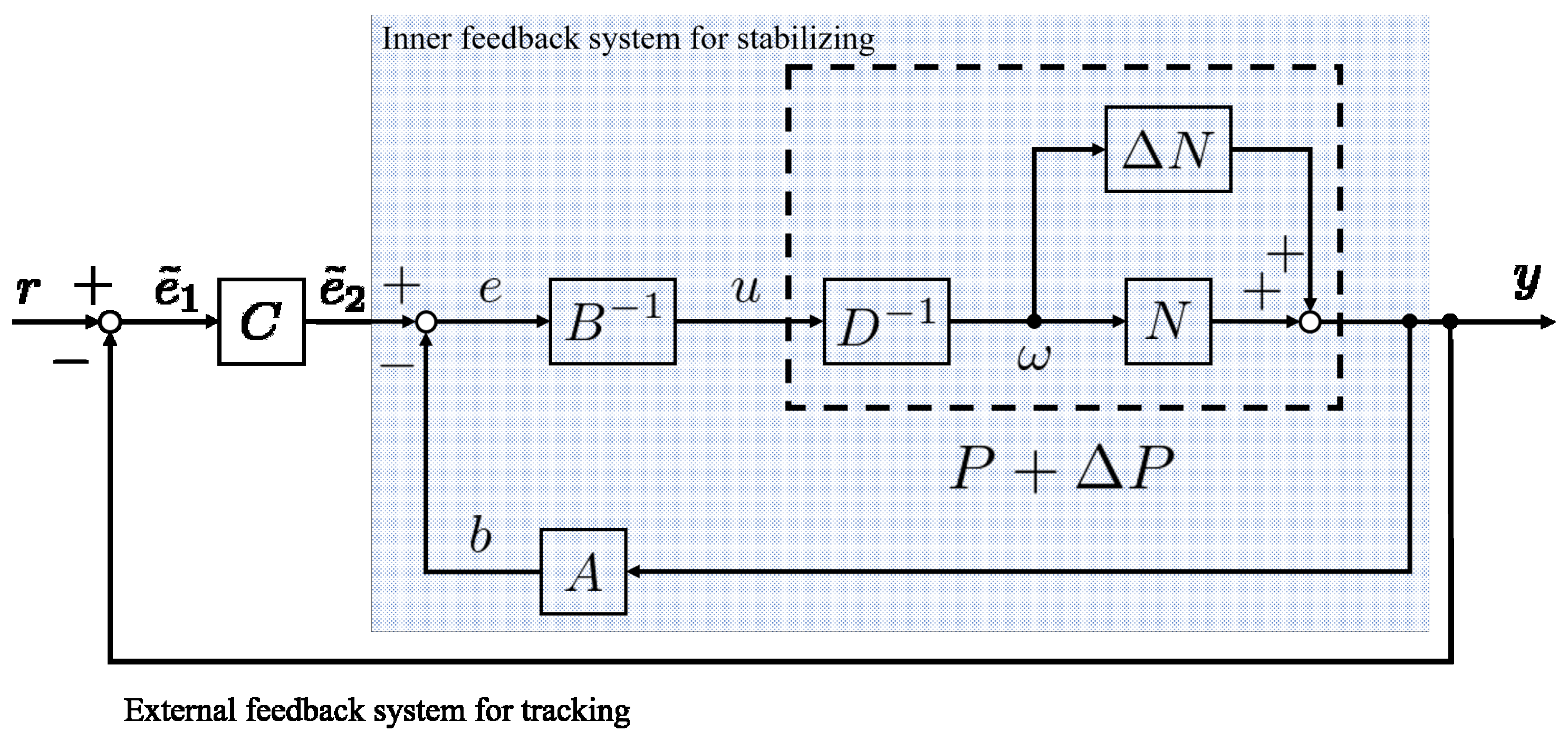
In this section, for the motion control of the actuator, a nonlinear feedback control system shown in Figure 6 is designed based on operator theory [6]. This system is composed of an inner feedback system and an external feedback system. The inner system stabilizes an unstable plant. The external one makes output track desired value by controller C. Each operator C, A, B 1 , D 1 and N is expressed as mapping function, satisfying the following design limitation: A is stable, B is stable and invertible, D is invertible and can include unstable factor, and N is stable and can include nonlinear factor.

2.3.1. Right Coprime Factorization

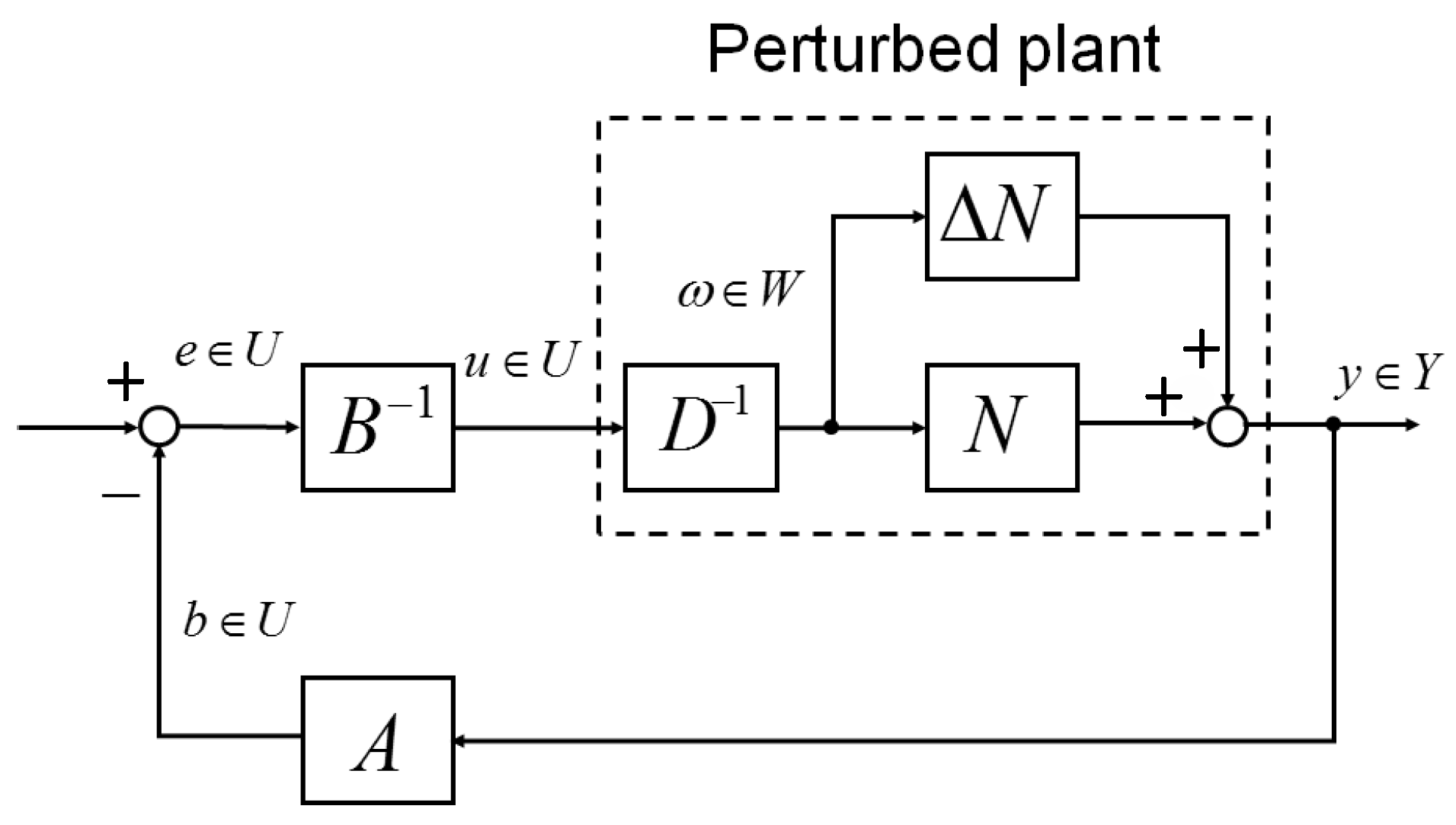
P is usually unstable in nonlinear control systems. In this case, the system can be stabilized by using right coprime factorization [6]. D 1 and N are called right factorization of P in Figure 7. In a simple term, P is considered as a composite function such as P = N D 1 or P = N D 1 . N is stable function, and D 1 is an inverse and stable function of D while D may be unstable operator. Operator A and B 1 take a roll as feedback and feed-forward controller respectively for unstable D, so that the overall system in Figure 7 is stable as long as each operator satisfies the Bezout identity represented as
A N + B D = M ,
where M is an unimodular operator; both M and M 1 are stable.
It should be, however, be noted that the system in Figure 7 supports stability but not tracking performance. A controller C should be added to the system like Figure 6 to make the output track the desired value.

2.3.2. Robust Stability

The above system in Figure 7 also has robustness for uncertainty Δ N . This paper supposes that Δ N is modelling error. The system in Figure 7 is robust stable, if the following condition is satisfied as
( A ( N + Δ N ) A N ) I 1 L i p < 1 ,
noting that · L i p is Lipschiz norm represented as
Q : = s u p Q ( x ) Q ( x ˜ ) Y x x ˜ X ,
where Q ( x ) is a linear or nonlinear operator mapping from input space X to output space Y.

2.3.3. Designing Operators

The operators are designed in this section by using the right coprime factorization and the new model (10). There are, actually, many sets of operators (N, D 1 , A, B 1 ) satisfying the Bezout identity shown as Equation (14). In this study, with repeating simulation, N, D 1 , B 1 operator was designed as:
y ( t ) = N ( ω ) ( t ) = n C 2 ω ( t ) 2 C 1 ,
ω ( t ) = D 1 ( u ) ( t ) = n C 2 2 4 C 1 C 3 u ( t ) ,
B ( u ) ( t ) = K u ( t ) ,
where K is parameter of stabilizing controller B 1 . D 1 included potentially unstable factor, u ( t ) . A was derived from N, D 1 , B 1 based on Equation (14) as below:
A ( y ) ( t ) = ( I B D ) N 1 = N 1 B D N 1 = n C 2 2 C 1 y ( t ) K 4 C 1 C 3 n 2 ( n 2 C 2 2 ( n C 2 2 C 1 y ( t ) ) 2 ) = n C 2 n C 1 + K C 2 n 2 C 3 y ( t ) + K C 1 n 2 C 3 y 2 ( t ) ,
where I is identity operator mapping a signal to the same space, belonging to unimodular operator M. Moreover, tracking controller C is designed as:
C ( e ˜ ) ( t ) = k i 0 t e ˜ 1 ( τ ) d τ + k p e ˜ 1 ( t ) ,
where k i and k p are parameters of tracking controller.
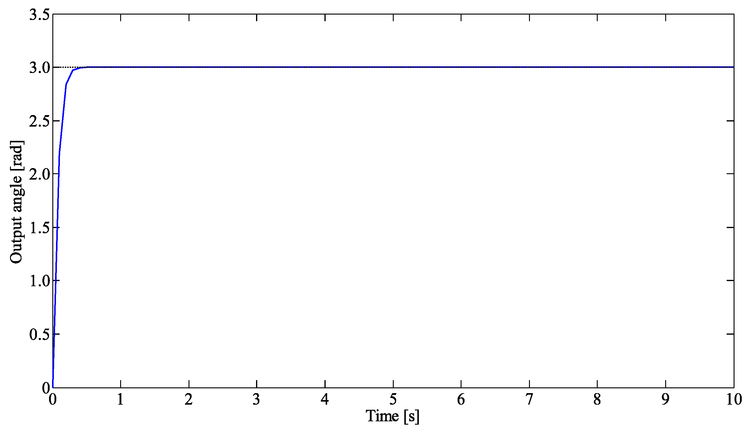
Figure 8 shows a result of simulation in the case where controller A, B 1 and C are used for the nominal plant. This simulation was conducted using MATLAB. Each of the parameters was determined as K = 1 , k i = 11 and k p = 0.0001 . The desired value was configured as 3.0 rad. E were determined by comparison of Equation (1) and the result on the strain-stress test [3] of the silicon rubber of the actuator. The other parameters was the same as Table 1.
From Figure 8, it is observed that the output started rising up and tracked desired value with stability. The stabilizing controller A, B 1 and tracking controller C are, therefore, expected to be the effective controllers for the actual plant.

3. Results

3.1. Experiment

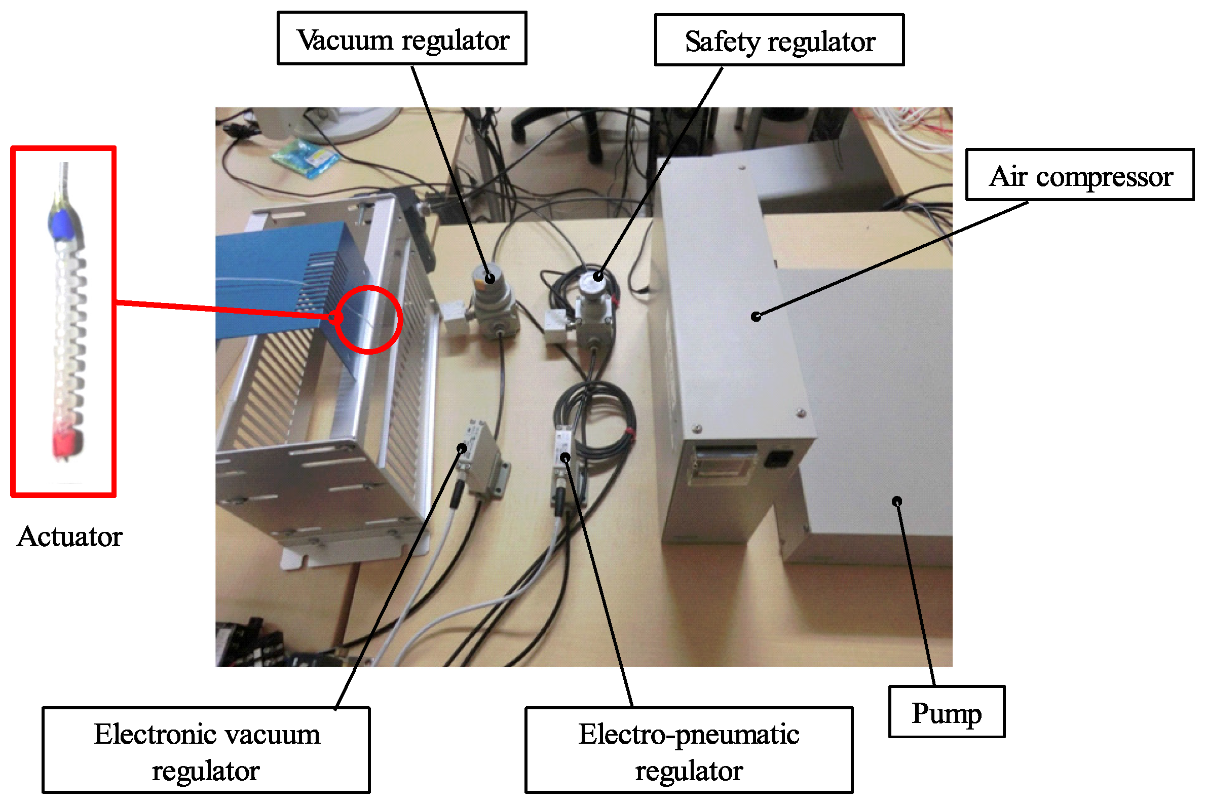
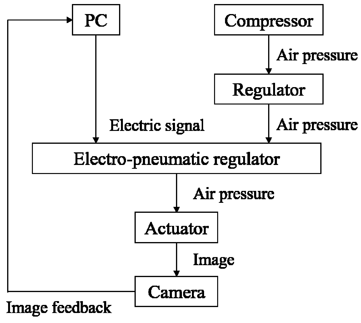
Experimental system is shown in Figure 9 and experimental flow is shown in Figure 10. This experiment verifies if the system proposed above achieves tracking performance. In this research, only equipment for positive pressure was used: an air compressor (DPP-AYAD, Koganei, Tokyo, Japan), a safety regulator (RP1000-8-07, CKD, Aichi, Japan), an electro-pneumatic regulator (ITV0010-0CS, SMC, Tokyo, Japan), PC sending electrical signal, and the actuator. The actuator was painted with its head red and root blue beforehand. As can be seen in Figure 10, the air compressor provides a pressure, and the safety regulator then converts the pressure to at most 60 kPa so as to avoid breaking the actuator. The computer sends an electrical signal which decides an opening of the electro-pneumatic regulator. The desired pressure, therefore, is obtained and sent into the actuator.
Output was captured as image by a camera, and then, fed back into the computer every 0.1 s. Bending angle was computed based on the following algorithm.
  • Convert captured color image to a gray scale.
  • Dissolve the image into three pixel numbers; R, B, G.
  • Extract only R pixels from the image in comparison with a gray scale.
  • Find the center coordinate from extracted R pixel area.
  • Do the same process as 4 and 5 to B pixels.
  • Calculate bending angle from center coordinate of R and B area.
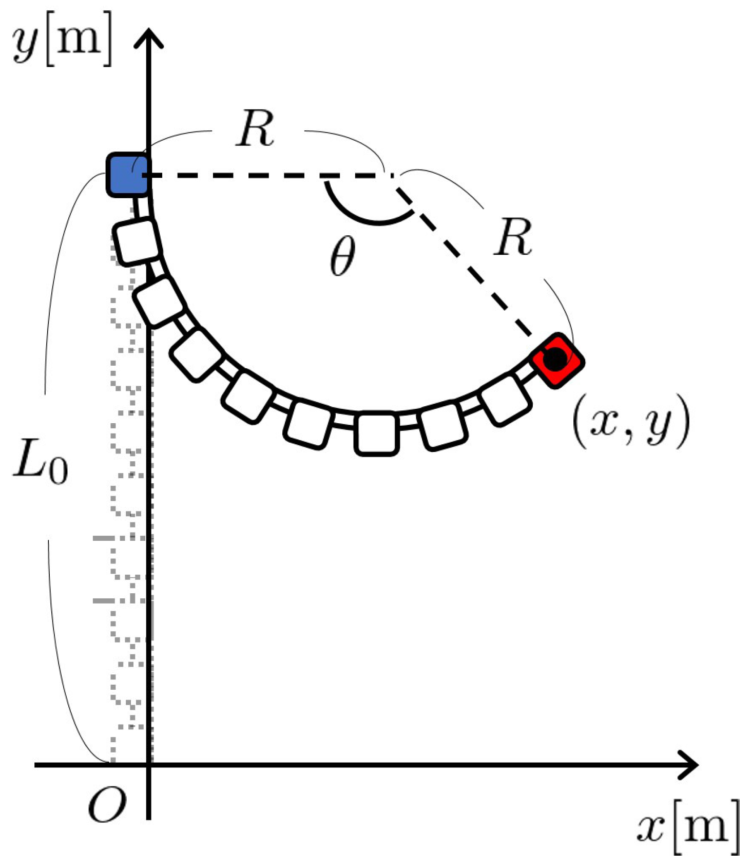
This flow was repeated for 10 min. The output angles were recorded in a CSV file. Process 6 was made based on a model for measurement in Figure 11. This model gives Equations (22) and (23) below.
R = x 2 + y 2 2 L 0 + L 0 2 2 x ,
θ = 2 cos 1 L 0 y x 2 + ( L 0 y ) 2 ,
where ( x , y ) is obtained from camera.

3.2. Experimental Result

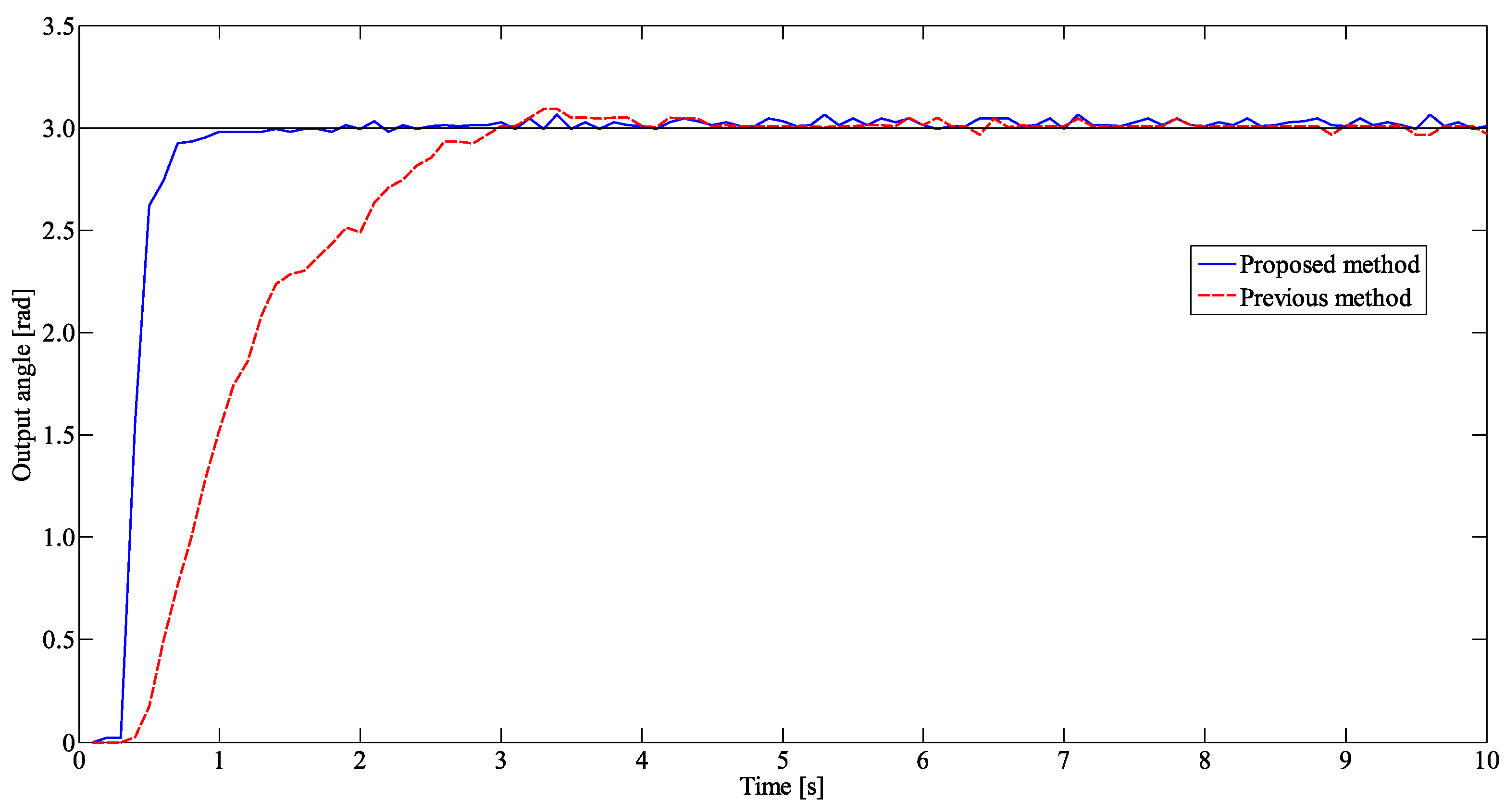
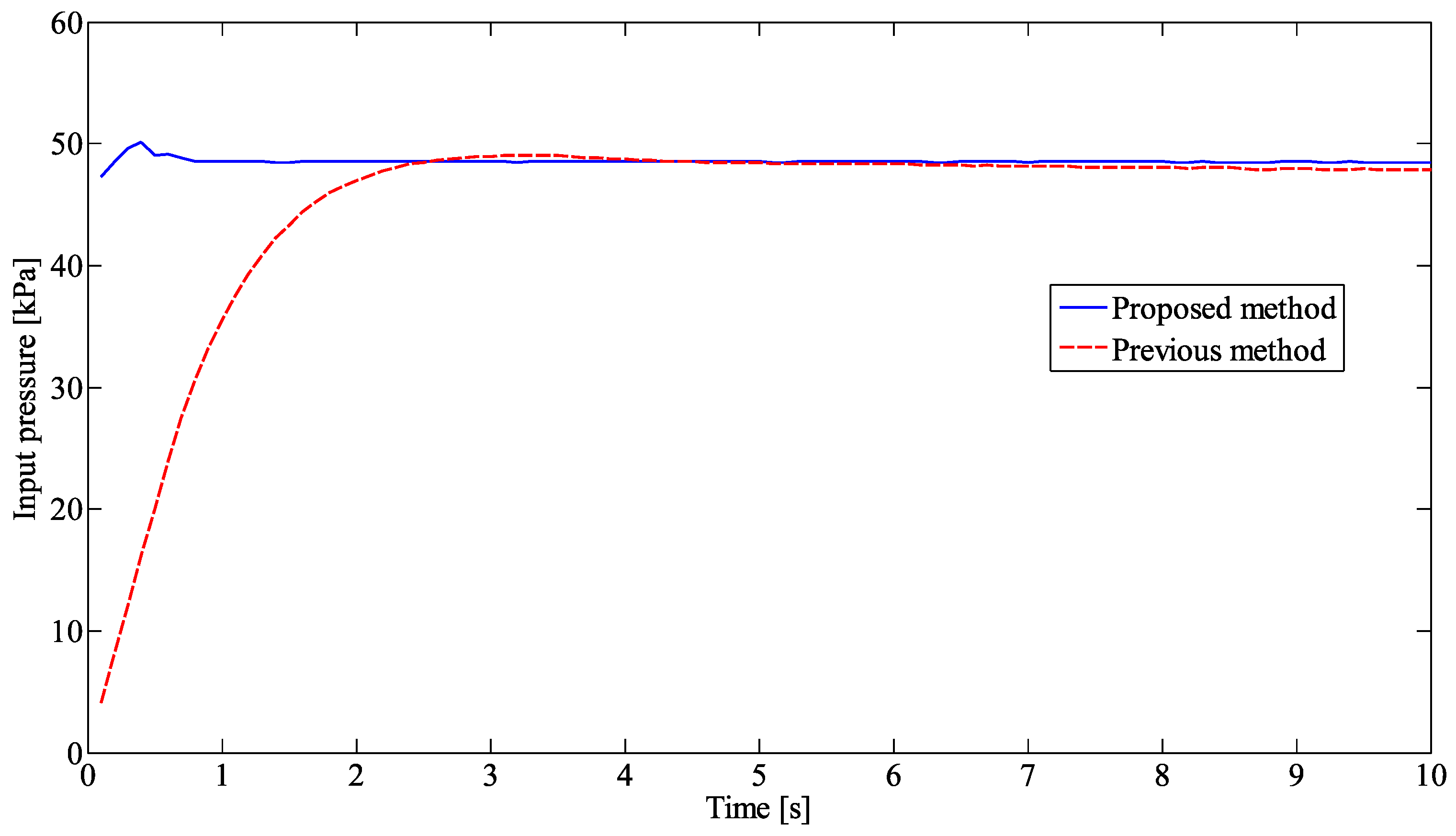
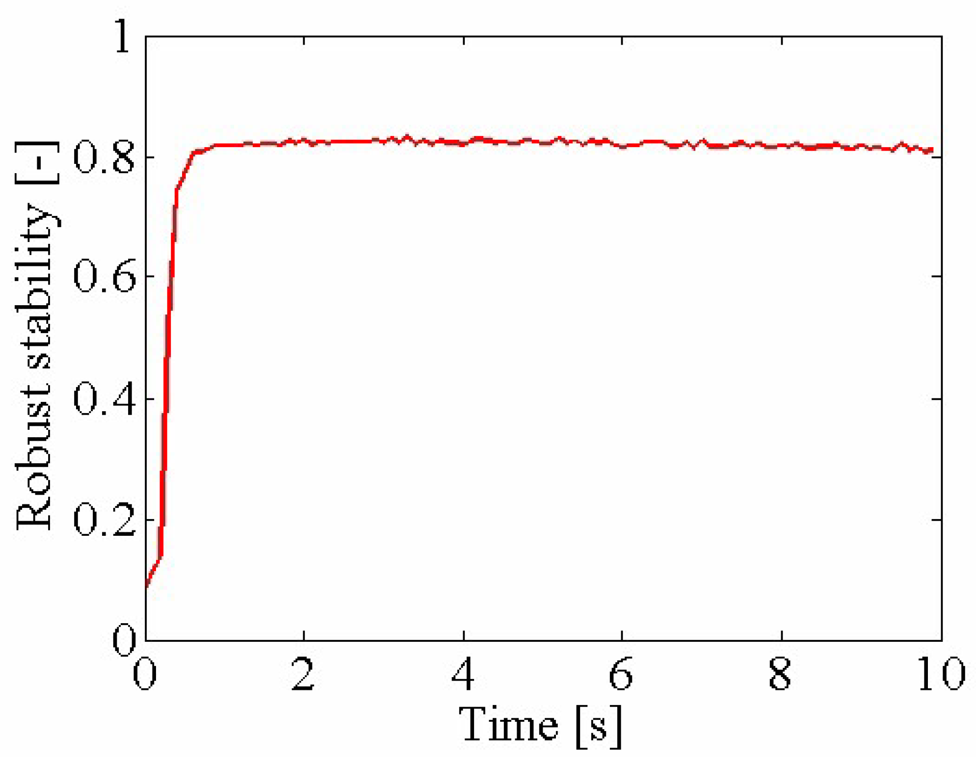
In a previous study [12], a first model was proposed and an operator-based control system including the model was designed. Its tracking performance was verified by an experiment. Another study [16] proposed an appropriate control method for the actuator based on [12]. This study indicates that the redesigned system is more effective for tracking performance, by an experiment. The obtained result is compared with the previous method: the control system including the first model [12]. The experiment is carried out by following the above section, and needs a desired value, parameters of the stabilizing controller and the tracking controllers: r, K, k p and k i respectively. The desired value was configured as 3.0 rad and the controller parameters were chosen as K = 0.0006 , k p = 10 and k i = 0.25 by repeating try and error. The other parameters were the same as Table 1. Figure 12 and Figure 13 show the result of output angle and the input pressure, and Figure 14 show the result of analysis on the robustness to uncertainty using Equations (15) and (16).
As can be seen in Figure 12, the two outputs kept nearly 0 kPa and then, started rising up while the simulation in Figure 8 showed quick reaction. This dead time is caused by the dead zone shown in Figure 5. After the dead time, both of the two outputs soon tracked the desired value sufficiently. However, the output of the proposed method tracked faster than the previous method by as much as 1.7 s. This means that proposed controllers improved the tracking performance. In Figure 13, the input pressure by the proposed method also indicated a faster rise than the previous one, contributing to improve output performance. Moreover, in Figure 14, the value of Lipschitz norm is under 1, so that the overall system is robust stable for Δ N , because the result of the analysis satisfies Equation (15). The proposed model therefore proved to be better than the conventional one.

4. Conclusions

Previous studies have documented that the miniature pneumatic bending rubber actuator is well controlled by modelling and designing a feedback system. However, the model has caused modelling error, and it therefore has led to affecting the feedback system. This study addressed the remodelling of the actuator to reduce the error and controlling it by using right coprime factorization and by adding PI controller. The experiment indicated that proposed method improves the tracking performance while keeping stability, so that the effectiveness of the detail modelling is verified for the feedback system. The tracking controller, however, needs devising for better tracking performance. Moreover, the control for gripping force of the actuator is actually important for sensitive operations. Future works should include these problems.

Author Contributions

M.S. remodelled and conducted experiment for the actuator and wrote the paper; M.D. suggested technical support and gave overall comments on the paper; S.W. developed the actuator and prepared the experimental set-up.

Conflicts of Interest

The authors declare no conflict of interest.

Abbreviations

The following abbreviation is used in this manuscript:
FMAFlexible micro actuator

References

  1. Chen, X.; Su, C.Y. Adaptive Control for Ionic Polymer-Metal Composite Actuators. In Proceedings of the 2016 IEEE Transactions on Systems, Man, and Cybernetics: Systems, Sacramento, CA, USA, 1 October 2016; Volume 46, pp. 1468–1477. [Google Scholar] [CrossRef]
  2. Suzumori, K.; Iikura, S.; Tanaka, H. Development of flexible microactutor and its applications to robotic mechanisms. In Proceedings of the IEEE International Conference on Robotics and Automation, Sacramento, CA, USA, 9–11 April 1991; Volume 4, pp. 1622–1627. [Google Scholar] [CrossRef]
  3. Wakimoto, S.; Suzumori, K.; Ogura, K. Miniature pneumatic curling rubber actuator generating bidirectional motion with one air-supply tube. Adv. Robot. 2011, 25, 1311–1330. [Google Scholar] [CrossRef]
  4. Mosadegh, B.; Polygerinos, P.; Keplinger, C.; Wennstedt, S.; Shepherd, R.F.; Gupta, U.; Shim, J.; Bertoldi, K.; Walsh, C.J.; Whitesides, G.M. Pneumatic Networks for Soft Robotics that Actuate Rapidly. Adv. Funct. Mater 2014, 24, 2163–2170. [Google Scholar] [CrossRef] [Green Version]
  5. Yoshioka, R.; Wakimoto, S.; Yamamoto, Y.; Suzumori, K. Development of a micro pneumatic actuator realizing bidirectional bending motions. In Proceedings of the 2013 JSME Conference on Robotics and Mechatronics, Tsukuba, Japan, 22–25 May 2013; Volume 5, pp. 2A1-D06(1)–2A1-D06(3). [Google Scholar] [CrossRef]
  6. Deng, M. Operator-Based Bonlinear Control Systems Design and Applications; Willy-IEEE Press: Piscataway, NJ, USA, 2014. [Google Scholar]
  7. Deng, M.; Inoue, A.; Ishikawa, K. Operator-based nonlinear feedback control design using robust right coprime factorization. IEEE Trans. Autom. Control 2006, 51, 645–648. [Google Scholar] [CrossRef]
  8. Chen, G.; Han, Z. Robust right coprime factorization and robust stabilization of nonlinear feedback control system. IEEE Trans. Autom. Control 1998, 43, 645–648. [Google Scholar] [CrossRef]
  9. Deng, M.; Bu, N.; Inoue, A. Output tracking of nonlinear feedback systems with perturbation based on robust right coprime factorization. Int. J. Innov. Comput. Inf. Control 2009, 5, 3359–3366. [Google Scholar]
  10. Wang, A.; Deng, M. Robust nonlinear multivariable tracking control design to a manipulator with unknown uncertainties using operator-based robust right coprime factorization. Trans. Inst. Meas. Control 2013, 35, 788–797. [Google Scholar] [CrossRef]
  11. Deng, M.; Bu, N. Robust control for nonlinear systems with unknown perturbations using simplified robust right coprime factorization. Int. J. Control 2012, 85, 842–850. [Google Scholar] [CrossRef]
  12. Deng, M.; Kawashima, T. Adaptive nonlinear sensorless control for an uncertain miniature pneumatic curling rubber actuator using passivity and robust right coprime factorization. IEEE Trans. Control Syst. Technol. 2016, 24, 318–324. [Google Scholar] [CrossRef]
  13. Miyagawa, T.; Toya, K.; Kubota, Y. Static characteristics of pneumatic soft actuator using fiber reinforced rubber. In Proceedings of the JSME Conference on Robotics and Mechatronics, Akita, Japan, 10–12 May 2007; pp. 1A2–A01(1)–1A2–A01(4). [Google Scholar] [CrossRef]
  14. Kim, B.; Lee, S.B.; Lee, J.; Cho, S.; Park, H.; Yeom, S.; Park, S.H. A comparison among neo-hookean model, mooney-rivlin model, and ogden model for chloroprene rubber. Int. J. Precis. Eng. Manuf. 2012, 13, 759–764. [Google Scholar] [CrossRef]
  15. Editorial Board. Nyumonkouza yasashigomunobutsururi daisankou gomudanseitonendanseinokiso. [Introductory course of simple physics of rubber: No. 3 Basics of rubber elasticity and viscoelasticity]. J. SRI. Jpn. 2007, 80, 404–407. (In Japanese) [Google Scholar]
  16. Fujita, K.; Deng, M.; Wakimoto, S. A Miniature bending rubber controlled by using the PSO-SVR-based motion estimation method with the generalized gaussian kernel. Actuators 2017, 6. [Google Scholar] [CrossRef]
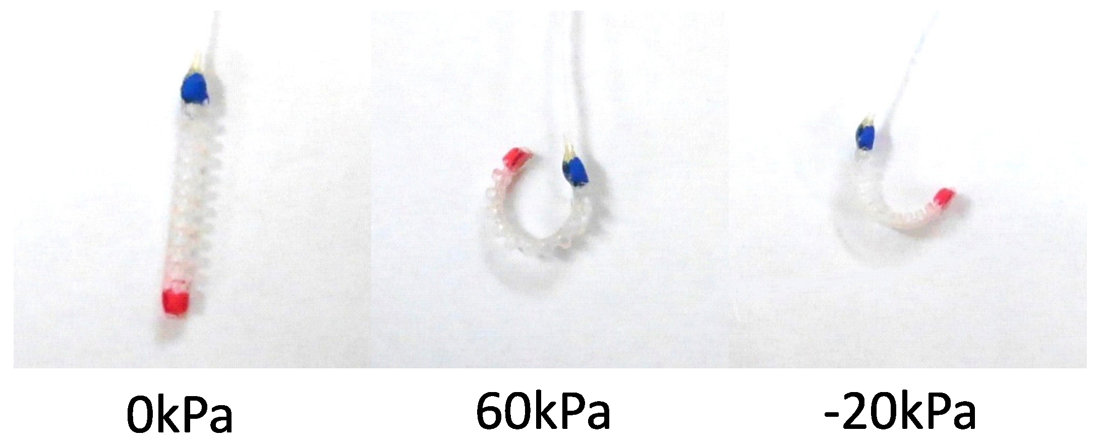
Figure 1. The moving of the actuator.
Actuators 07 00026 g001
Figure 2. The comparison of neo-Hookean model and Hooke’s model.
Actuators 07 00026 g002
Figure 3. (a) The model for analysis; (b) Three forces working on bellow; (c) The strain on the outside compared with the inside; (d) Three moments working on joint between small channel and large chamber.
Actuators 07 00026 g003
Figure 4. (a) f 1 working on a chamber or f 2 working on a channel; the chamber and the channel are geometry similar, so that f 1 and f 2 also work similarly; (b) f p working on the surface.
Actuators 07 00026 g004
Figure 5. The comparison of proposed model and previous model.
Actuators 07 00026 g005
Figure 6. The operator-based nonlinear control feedback system.
Actuators 07 00026 g006
Figure 7. The stabilized feedback system in the overall system of Figure 6.
Actuators 07 00026 g007
Figure 8. The result of simulation.
Actuators 07 00026 g008
Figure 9. Experimental system.
Actuators 07 00026 g009
Figure 10. Experimental flow.
Actuators 07 00026 g010
Figure 11. The model for computing the output angle.
Actuators 07 00026 g011
Figure 12. The experimental result of the proposed method compared with previous method.
Actuators 07 00026 g012
Figure 13. The input pressure of the proposed method compared with previous method.
Actuators 07 00026 g013
Figure 14. The analysis of robust stability.
Actuators 07 00026 g014
Table 1. The parameters of the actuator.
ParameterDefinitionValue
lInitial length of the actuator 0.66 × 10 3 m
tThickness of the rubber 0.15 × 10 3 m
r 1 Internal radius of small chambers 0.25 × 10 3 m
R 1 Representative radius of small chambers 0.325 × 10 3 m
r 2 Internal radius of large chambers 0.85 × 10 3 m
R 2 Representative radius of large chambers 0.925 × 10 3 m
nNumber of the bellows11
EYoung’s modulus 0.96 × 10 6 Pa